

Poste à souder MIG
MIG/MAG Welding
Schutzgasschweißgerät
Soldadura MIG
Аппараты MIG
MIG Lasapparaat
Machina di saldatura MIG
FR
EN
DE
ES
RU
NL
IT
P 2-8 / 53-68
P 9-15 / 53-68
P 16-22 / 53-68
P 23-29 / 53-68
P 30-37 / 53-68
P 38-45 / 53-68
P 46-52 / 53-68
C51321 - V15 - 10/05/2017
www.gys.fr
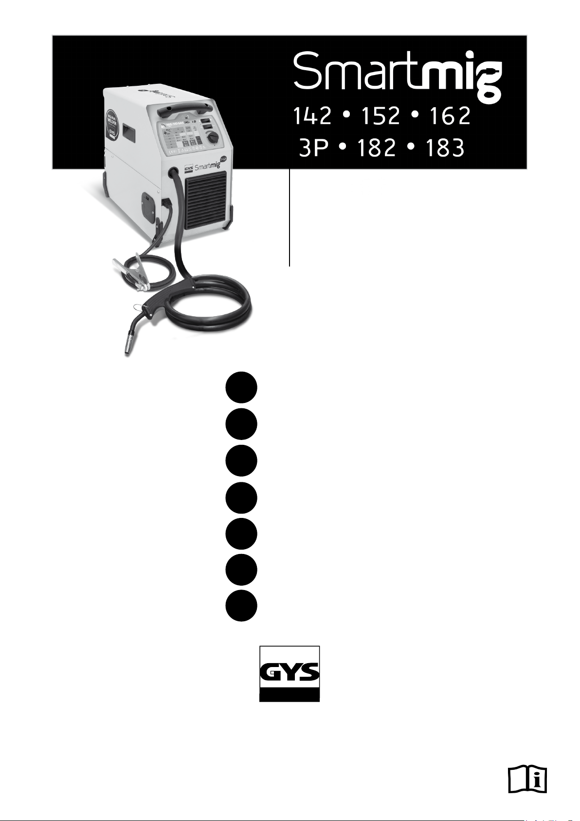
SMARTMIG
FR
AVERTISSEMENTS - RÈGLES DE SÉCURITÉ
CONSIGNE GÉNÉRALE
Ces instructions doivent être lues et bien comprises avant toute opération.
Toute modication ou maintenance non indiquée dans le manuel ne doit pas être entreprise.
Tout dommage corporel ou matériel dû à une utilisation non-conforme aux instructions de ce manuel ne pourra être retenu à la charge du fabricant.
En cas de problème ou d’incertitude, consulter une personne qualiée pour manier correctement l’installation.
ENVIRONNEMENT
Ce matériel doit être utilisé uniquement pour faire des opérations de soudage dans les limites indiquées par la plaque signalétique et/ou le manuel.
Il faut respecter les directives relatives à la sécurité. En cas d’utilisation inadéquate ou dangereuse, le fabricant ne pourra être tenu responsable.
L’installation doit être utilisée dans un local sans poussière, ni acide, ni gaz inammable ou autres substances corrosives de même pour son stockage.
S’assurer d’une circulation d’air lors de l’utilisation.
Plages de température :
Utilisation entre -10 et +40°C (+14 et +104°F).
Stockage entre -20 et +55°C (-4 et 131°F).
Humidité de l’air :
Inférieur ou égal à 50% à 40°C (104°F).
Inférieur ou égal à 90% à 20°C (68°F).
Altitude :
Jusqu’à 1000 m au-dessus du niveau de la mer (3280 pieds).
PROTECTIONS INDIVIDUELLE ET DES AUTRES
Le soudage à l’arc peut être dangereux et causer des blessures graves voire mortelles.
Le soudage expose les individus à une source dangereuse de chaleur, de rayonnement lumineux de l’arc, de champs électromagnétiques (attention
au porteur de pacemaker), de risque d’électrocution, de bruit et d’émanations gazeuses.
Pour bien se protéger et protéger les autres, respecter les instructions de sécurité suivantes :
An de se protéger de brûlures et rayonnements, porter des vêtements sans revers, isolants, secs, ignifugés et en bon état, qui
couvrent l’ensemble du corps.
Utiliser des gants qui garantissent l’isolation électrique et thermique.
Utiliser une protection de soudage et/ou une cagoule de soudage d’un niveau de protection sufsant (variable selon les applica-
tions). Protéger les yeux lors des opérations de nettoyage. Les lentilles de contact sont particulièrement proscrites.
Il est parfois nécessaire de délimiter les zones par des rideaux ignifugés pour protéger la zone de soudage des rayons de l’arc,
des projections et des déchets incandescents.
Informer les personnes dans la zone de soudage de ne pas xer les rayons de l’arc ni les pièces en fusion et de porter les vêtements adéquats pour se protéger.
Utiliser un casque contre le bruit si le procédé de soudage atteint un niveau de bruit supérieur à la limite autorisée (de même pour
toute personne étant dans la zone de soudage).
Tenir à distance des parties mobiles (ventilateur) les mains, cheveux, vêtements.
Ne jamais enlever les protections carter du groupe froid lorsque la source de courant de soudage est sous tension, le fabricant ne
pourrait être tenu pour responsable en cas d’accident.
Les pièces qui viennent d’être soudées sont chaudes et peuvent provoquer des brûlures lors de leur manipulation. Lors d’intervention d’entretien sur la torche ou le porte-électrode, il faut s’assurer que celui-ci soit sufsamment froid en attendant au moins 10
minutes avant toute intervention. Le groupe froid doit être allumé lors de l’utilisation d’une torche refroidie eau an d’être sûr que
le liquide ne puisse pas causer de brûlures.
Il est important de sécuriser la zone de travail avant de la quitter an de protéger les personnes et les biens.
FUMÉES DE SOUDAGE ET GAZ
Les fumées, gaz et poussières émis par le soudage sont dangereux pour la santé. Il faut prévoir une ventilation sufsante, un
apport d’air est parfois nécessaire. Un masque à air frais peut être une solution en cas d’aération insufsante.
Vérier que l’aspiration est efcace en la contrôlant par rapport aux normes de sécurité.
Attention le soudage dans des milieux de petites dimensions nécessite une surveillance à distance de sécurité. Par ailleurs le soudage de certains
matériaux contenant du plomb, cadmium, zinc ou mercure voire du béryllium peuvent être particulièrement nocifs, dégraisser également les pièces
avant de les souder.
Les bouteilles doivent être entreposées dans des locaux ouverts ou bien aérés. Elles doivent être en position verticale et maintenues à un support
ou sur un chariot.
Le soudage doit être proscrit à proximité de graisse ou de peinture.
2
SMARTMIG
RISQUES DE FEU ET D’EXPLOSION
Protéger entièrement la zone de soudage, les matières inammables doivent être éloignées d’au moins 11 mètres.
Un équipement anti-feu doit être présent à proximité des opérations de soudage.
Attention aux projections de matières chaudes ou d’étincelles et même à travers des ssures, elles peuvent être source d’incendie ou d’explosion.
Éloigner les personnes, les objets inammables et les containers sous pressions à une distance de sécurité sufsante.
Le soudage dans des containers ou des tubes fermés est à proscrire et dans le cas où ils sont ouverts il faut les vider de toute matière inammable
ou explosive (huile, carburant, résidus de gaz …).
Les opérations de meulage ne doivent pas être dirigées vers la source de courant de soudage ou vers des matières inammables.
BOUTEILLES DE GAZ
Le gaz sortant des bouteilles peut être source de suffocation en cas de concentration dans l’espace de soudage (bien ventiler).
Le transport doit être fait en toute sécurité : bouteilles fermées et la source de courant de soudage éteinte. Elles doivent être
entreposées verticalement et maintenues par un support pour limiter le risque de chute.
Fermer la bouteille entre deux utilisations. Attention aux variations de température et aux expositions au soleil.
La bouteille ne doit pas être en contact avec une amme, un arc électrique, une torche, une pince de masse ou toutes autres sources de chaleur ou
d’incandescence.
Veiller à la tenir éloignée des circuits électriques et de soudage et donc ne jamais souder une bouteille sous pression.
Attention lors de l’ouverture du robinet de la bouteille, il faut éloigner la tête la robinetterie et s’assurer que le gaz utilisé est approprié au procédé de
soudage.
FR
SÉCURITÉ ÉLECTRIQUE
Le réseau électrique utilisé doit impérativement avoir une mise à la terre. Utiliser la taille de fusible recommandée sur le tableau
signalétique.
Une décharge électrique peut être une source d’accident grave direct ou indirect, voire mortel.
Ne jamais toucher les parties sous tension à l’intérieur comme à l’extérieur de la source de courant sous-tension (Torches, pinces, câbles, électrodes)
car celles-ci sont branchées au circuit de soudage.
Avant d’ouvrir la source de courant de soudage, il faut la déconnecter du réseau et attendre 2 minutes. an que l’ensemble des condensateurs soit
déchargé.
Ne pas toucher en même temps la torche ou le porte-électrode et la pince de masse.
Veiller à changer les câbles, torches si ces derniers sont endommagés, par des personnes qualiées et habilitées. Dimensionner la section des câbles
en fonction de l’application. Toujours utiliser des vêtements secs et en bon état pour s’isoler du circuit de soudage. Porter des chaussures isolantes,
quel que soit le milieu de travail.
CLASSIFICATION CEM DU MATÉRIEL
Ce matériel de Classe A n’est pas prévu pour être utilisé dans un site résidentiel où le courant électrique est fourni par le réseau
public d’alimentation basse tension. Il peut y avoir des difcultés potentielles pour assurer la compatibilité électromagnétique
dans ces sites, à cause des perturbations conduites, aussi bien que rayonnées à fréquence radioélectrique
Ce matériel n’est pas conforme à la CEI 61000-3-12 et est destiné à être raccordé à des réseaux basse tension privés connectés
au réseau public d’alimentation seulement au niveau moyenne et haute tension. S’il est connecté à un réseau public d’alimentation
basse tension, il est de la responsabilité de l’installateur ou de l’utilisateur du matériel de s’assurer, en consultant l’opérateur du
réseau de distribution, que le matériel peut être connecté.
ÉMISSIONS ÉLECTROMAGNÉTIQUES
Le courant électrique passant à travers n’importe quel conducteur produit des champs électriques et magnétiques (EMF)
localisés. Le courant de soudage produit un champ électromagnétique autour du circuit de soudage et du matériel de soudage.
Les champs électromagnétiques EMF peuvent perturber certains implants médicaux, par exemple les stimulateurs cardiaques. Des mesures
de protection doivent être prises pour les personnes portant des implants médicaux. Par exemple, restrictions d’accès pour les passants ou une
évaluation de risque individuelle pour les soudeurs.
Tous les soudeurs devraient utiliser les procédures suivantes an de minimiser l’exposition aux champs électromagnétiques provenant du circuit de
soudage:
• positionner les câbles de soudage ensemble – les xer les avec une attache, si possible;
• se positionner (torse et tête) aussi loin que possible du circuit de soudage;
• ne jamais enrouler les câbles de soudage autour du corps;
• ne pas positionner le corps entre les câbles de soudage. Tenir les deux câbles de soudage sur le même côté du corps;
• raccorder le câble de retour à la pièce mise en œuvre aussi proche que possible à la zone à souder;
3
SMARTMIG
• ne pas travailler à côté de la source de courant de soudage, ne pas s’assoir dessus ou ne pas s’y adosser ;
• ne pas souder lors du transport de la source de courant de soudage ou le dévidoir.
Les porteurs de stimulateurs cardiaques doivent consulter un médecin avant d’utiliser ce matériel.
L’exposition aux champs électromagnétiques lors du soudage peut avoir d’autres effets sur la santé que l’on ne connaît pas
encore.
DES RECOMMANDATIONS POUR ÉVALUER LA ZONE ET L’INSTALLATION DE SOUDAGE
Généralités
L’utilisateur est responsable de l’installation et de l’utilisation du matériel de soudage à l’arc suivant les instructions du fabricant. Si des perturbations
électromagnétiques sont détectées, il doit être de la responsabilité de l’utilisateur du matériel de soudage à l’arc de résoudre la situation avec l’assistance
technique du fabricant. Dans certains cas, cette action corrective peut être aussi simple qu’une mise à la terre du circuit de soudage. Dans d’autres cas, il
peut être nécessaire de construire un écran électromagnétique autour de la source de courant de soudage et de la pièce entière avec montage de ltres
d’entrée. Dans tous les cas, les perturbations électromagnétiques doivent être réduites jusqu’à ce qu’elles ne soient plus gênantes.
Evaluation de la zone de soudage
Avant d’installer un matériel de soudage à l’arc, l’utilisateur doit évaluer les problèmes électromagnétiques potentiels dans la zone environnante. Ce
qui suit doit être pris en compte:
a) la présence au-dessus, au-dessous et à côté du matériel de soudage à l’arc d’autres câbles d’alimentation, de commande, de signalisation et de
téléphone;
b) des récepteurs et transmetteurs de radio et télévision;
c) des ordinateurs et autres matériels de commande;
d) du matériel critique de sécurité, par exemple, protection de matériel industriel;
e) la santé des personnes voisines, par exemple, emploi de stimulateurs cardiaques ou d’appareils contre la surdité;
f) du matériel utilisé pour l’étalonnage ou la mesure;
g) l’immunité des autres matériels présents dans l’environnement.
L’utilisateur doit s’assurer que les autres matériels utilisés dans l’environnement sont compatibles. Cela peut exiger des mesures de protection
supplémentaires;
h) l’heure du jour où le soudage ou d’autres activités sont à exécuter.
FR
La dimension de la zone environnante à prendre en compte dépend de la structure du bâtiment et des autres activités qui s’y déroulent. La zone
environnante peut s’étendre au-delà des limites des installations.
Evaluation de l’installation de soudage
Outre l’évaluation de la zone, l’évaluation des installations de soudage à l’arc peut servir à déterminer et résoudre les cas de perturbations. Il convient
que l’évaluation des émissions comprenne des mesures in situ comme cela est spécié à l’Article 10 de la CISPR 11:2009. Les mesures in situ
peuvent également permettre de conrmer l’efcacité des mesures d’atténuation.
RECOMMANDATION SUR LES MÉTHODES DE REDUCTION DES EMISSIONS ÉLECTROMAGNÉTIQUES
a. Réseau public d’alimentation: Il convient de raccorder le matériel de soudage à l’arc au réseau public d’alimentation selon les recommandations
du fabricant. Si des interférences se produisent, il peut être nécessaire de prendre des mesures de prévention supplémentaires telles que le ltrage
du réseau public d’alimentation. Il convient d’envisager de blinder le câble d’alimentation dans un conduit métallique ou équivalent d’un matériel de
soudage à l’arc installé à demeure. Il convient d’assurer la continuité électrique du blindage sur toute sa longueur. Il convient de raccorder le blindage
à la source de courant de soudage pour assurer un bon contact électrique entre le conduit et l’enveloppe de la source de courant de soudage.
b. Maintenance du matériel de soudage à l’arc : Il convient que le matériel de soudage à l’arc soit soumis à l’entretien de routine suivant les
recommandations du fabricant. Il convient que tous les accès, portes de service et capots soient fermés et correctement verrouillés lorsque le matériel
de soudage à l’arc est en service. Il convient que le matériel de soudage à l’arc ne soit modié en aucune façon, hormis les modications et réglages
mentionnés dans les instructions du fabricant. Il convient, en particulier, que l’éclateur d’arc des dispositifs d’amorçage et de stabilisation d’arc soit
réglé et entretenu suivant les recommandations du fabricant.
c. Câbles de soudage : Il convient que les câbles soient aussi courts que possible, placés l’un près de l’autre à proximité du sol ou sur le sol.
d. Liaison équipotentielle : Il convient d’envisager la liaison de tous les objets métalliques de la zone environnante. Toutefois, des objets métalliques
reliés à la pièce à souder accroissent le risque pour l’opérateur de chocs électriques s’il touche à la fois ces éléments métalliques et l’électrode. Il
convient d’isoler l’opérateur de tels objets métalliques.
e. Mise à la terre de la pièce à souder : Lorsque la pièce à souder n’est pas reliée à la terre pour la sécurité électrique ou en raison de ses
dimensions et de son emplacement, ce qui est le cas, par exemple, des coques de navire ou des charpentes métalliques de bâtiments, une connexion
raccordant la pièce à la terre peut, dans certains cas et non systématiquement, réduire les émissions. Il convient de veiller à éviter la mise à la terre
des pièces qui pourrait accroître les risques de blessure pour les utilisateurs ou endommager d’autres matériels électriques. Si nécessaire, il convient
que le raccordement de la pièce à souder à la terre soit fait directement, mais dans certains pays n’autorisant pas cette connexion directe, il convient
que la connexion soit faite avec un condensateur approprié choisi en fonction des réglementations nationales.
f. Protection et blindage : La protection et le blindage sélectifs d’autres câbles et matériels dans la zone environnante peuvent limiter les problèmes
de perturbation. La protection de toute la zone de soudage peut être envisagée pour des applications spéciales.
TRANSPORT ET TRANSIT DE LA SOURCE DE COURANT DE SOUDAGE
La source de courant de soudage est équipée d’une (de) poignée(s) supérieure(s) permettant le portage à la main. Attention à ne
pas sous-évaluer son poids. La (les) poignée(s) n’est (ne sont) pas considérée(s) comme un moyen d’élingage.
Ne pas utiliser les câbles ou torche pour déplacer la source de courant de soudage. Elle doit être déplacée en position verticale.
Ne pas faire transiter la source de courant au-dessus de personnes ou d’objets.
Ne jamais soulever une bouteille de gaz et la source de courant en même temps. Leurs normes de transport sont distinctes. Il est préférable
d’enlever la bobine de l avant tout levage ou transport de la source de courant de soudage.
Les courants de soudage vagabonds peuvent détruire les conducteurs de terre, endommager l’équipement et les dispositifs
électriques et causer des échauffements de composants pouvant entrainer un incendie.
4
SMARTMIG
• Toutes les connexions de soudages doivent être connectées fermement, les vérier régulièrement !
• S’assurer que la xation de la pièce est solide et sans problèmes électriques !
• Attacher ou suspendre tous les éléments conducteurs d’électricité de la source de soudage comme le châssis, le chariot et les systèmes de levage
pour qu’ils soient isolés !
• Ne pas déposer d’autres équipements comme des perceuses, dispositifs d’affutage, etc sur la source de soudage, le chariot, ou les systèmes de
levage sans qu’ils soient isolés !
• Toujours déposer les torches de soudage ou portes électrodes sur une surface isolée quand ils ne sont pas utilisés !
INSTALLATION DU MATÉRIEL
• Mettre la source de courant de soudage sur un sol dont l’inclinaison maximum est de 10°.
• Prévoir une zone sufsante pour aérer la source de courant de soudage et accéder aux commandes.
• Ne pas utiliser dans un environnement comportant des poussières métalliques conductrices.
• La source de courant de soudage doit être à l’abri de la pluie battante et ne pas être exposée aux rayons du soleil.
• Le matériel est de degré de protection IP21, signiant :
- une protection contre l’accès aux parties dangereuses des corps solides de diam >12.5 mm et,
- une protection contre les chutes verticales de gouttes d’eau
Les câbles d’alimentation, de rallonge et de soudage doivent être totalement déroulés an d’éviter toute surchauffe.
Le fabricant n’assume aucune responsabilité concernant les dommages provoqués à des personnes et objets dus à une utilisation
incorrecte et dangereuse de ce matériel.
ENTRETIEN / CONSEILS
• L’entretien ne doit être effectué que par une personne qualiée. Un entretien annuel est conseillé.
• Couper l’alimentation en débranchant la prise, et attendre deux minutes avant de travailler sur le matériel. A l’intérieur, les
tensions et intensités sont élevées et dangereuses.
• Régulièrement, enlever le capot et dépoussiérer à la soufette. En proter pour faire vérier la tenue des connexions électriques
avec un outil isolé par un personnel qualié.
• Contrôler régulièrement l’état du cordon d’alimentation. Si le câble d’alimentation est endommagé, il doit être remplacé par le
fabricant, son service après-vente ou une personne de qualication similaire, an d’éviter tout danger.
• Laisser les ouïes de la source de courant de soudage libres pour l’entrée et la sortie d’air.
• Ne pas utiliser cette source de courant de soudage pour dégeler des canalisations, recharger des batteries/accumulateurs ou
démarrer des moteurs.
FR
INSTALLATION – FONCTIONNEMENT PRODUIT
DESCRIPTION
w
Merci de votre choix ! An de tirer le maximum de satisfaction de votre poste, veuillez lire avec attention ce qui suit:
Les produits SMARTMIG sont des postes de soudure traditionnels pour le soudage semi-automatique (MIG ou MAG) en courant continu (DC), et pour
le soudage MMA (SMARTMIG 3P uniquement). Ils permettent de souder tout type de l : acier, inox, alu, fourré (no gas). Le SMARTMIG 3P permet
de souder des électrodes jusqu’au Ø 3,2mm.
Le réglage de ces appareils est simplié grâce à la solution SMART.
ALIMENTATION ÉLECTRIQUE
Smartmig 142/152/162/3P/182 :
Ce matériel est livré avec une prise 16 A de type CEE7/7 et ne doit être utilisé que sur une installation électrique monophasée 230 V (50 - 60 Hz) à
trois ls avec un neutre relié à la terre.
Le courant effectif absorbé (I1eff) est indiqué sur l’appareil, pour les conditions d’utilisation maximales. Vérier que l’alimentation et ses protections
(fusible et/ou disjoncteur) sont compatibles avec le courant nécessaire en utilisation. Dans certains pays, il peut être nécessaire. de changer la prise
pour permettre une utilisation aux conditions maximales.
Smartmig 183 :
Ce matériel est livré avec prise 16 A de type EN 60309-1 et ne doit être utilisé que sur une installation électrique triphasée 400V (50-60 Hz) à
quatre ls avec un neutre relié à la terre.
Le courant effectif absorbé (I1eff) est indiqué sur le matériel, pour les conditions d’utilisation maximales. Vérier que l’alimentation et ses protections (fusible et/ou disjoncteur) sont compatibles avec le courant nécessaire en utilisation. Dans certains pays, il peut être nécessaire de changer la
prise pour permettre une utilisation aux conditions maximales.
DESCRIPTION DU POSTE (FIG-I)
1- Interrupteur marche/arrêt
2- Cordon d'alimentation
3- Poignée arrière
4- Support bobine
5- Raccord rapide gaz
6- Poignée de transport avant
7- Panneau de contrôle et tableau "Smart"
8- Moto-dévidoir
9- Roues arrières (sauf 142/152)
10- Connecteur de torche EURO (sauf 142)
11- Connecteur rapide 200A (3P uniquement)
12- Roues avant (sauf 142/152)
13- Câble de masse xe (sauf 3P)
14- Boîtier d'inversion de polarité (sauf 3P)
15- Chaine de xation pour bouteilles.
Attention : bien xer les bouteilles
SOUDAGE SEMI-AUTOMATIQUE EN ACIER/INOX (MODE MAG) (FIG-II)
Ces appareils peuvent souder du l acier et inox de Ø 0,6/0,8 ou 1,0 (excepté le modèle 142 et 152) (g II - A).
Le SMARTMIG 3P peut souder du l acier et inox de 0,6/0,8 ou 1,0 à condition de connecter le câble de masse sur la borne négative en face avant
(g I ).
Ces appareils sont livrés d’origine pour fonctionner avec un l Ø 0,8 en acier ou inox. Le tube contact, la gorge du galet, la gaine de la torche sont
prévus pour cette application.
5
SMARTMIG
Lors de l’utilisation du l de diamètre 0,6, il convient de changer le tube contact. Le galet du moto-dévidoir est un galet réversible 0,6/0,8. Dans ce
cas, le positionner de façon à lire 0,6. Pour souder du Ø 1,0, se munir d’un galet et d’un tube contact adaptés.
L’utilisation en acier ou inox nécessite un gaz spécique Argon + CO². La proportion de CO² varie selon l’utilisation. Pour le choix du gaz, demander
conseil à un distributeur de gaz. Le débit de gaz en acier se situe entre 12 et 18 l/mn selon l’environnement et l’expérience du soudeur.
FR
SOUDAGE SEMI-AUTOMATIQUE ALUMINIUM (FIG-II) (MODE MIG)
Les SMARTMIG 152, 162, 3P ,182 et 183 peuvent être équipés pour souder avec du l alu de Ø 0,8 ou 1,0 (g II-B).
Le SMARTMIG 3P peut souder du l alu de Ø 0,8 ou 1,0 à condition de connecter le câble de masse sur la borne négative en face avant (g I ).
Le SMARTMIG 142 peut être utilisé pour souder l’Alu de Ø0,8 de façon occasionnelle et non intensive. Dans ce cas, le l utilisé doit être dur pour
faciliter le dévidage (type AlMg5).
L’utilisation en aluminium nécessite un gaz spécique argon pur (Ar). Pour le choix du gaz, demander conseil à un distributeur de gaz. Le débit de
gaz en aluminium se situe entre 20 et 30 l/min selon l’environnement et l’expérience du soudeur. Voici les différences entre les utilisations acier et
aluminium :
- Utiliser des galets spéciques pour le soudage alu.
- Mettre un minimum de pression des galets presseurs du moto-dévidoir pour ne pas écraser le l.
- Utiliser le tube capillaire uniquement pour le soudage acier/inox.
- La préparation d’une torche alu demande une attention particulière. Elle possède une gaine téon an de réduire
les frottements. Ne pas couper la gaine au bord du raccord, elle doit dépasser de la longueur du tube capillaire qu’elle remplace et sert à guider
le l à partir des galets.
- Tube contact : utiliser un tube contact SPECIAL aluminium Ø 0,8 (réf : 041059-non fourni).
SOUDAGE EN MODE "NO GAS" (FIG. III)
Ces appareils permettent de souder avec du l fourré «No Gas» à condition d’inverser la polarité de soudage. Pour ce faire, mettre l’appareil horstension puis ouvrir la trappe (14) et procéder au branchement en suivant les indications de la gure III-C. Le poste est conguré d’origine en mode
« Gas ».
Le Smartmig 3P peut souder du l fourré «No Gas» à condition de connecter le câble de masse sur la borne positive en face avant (g I ).
SOUDAGE A L’ÉLECTRODE ENROBÉE (FIG. III) SMARTMIG 3P (MODE MMA)
Respecter les polarités indiquées sur l’emballage des électrodes.
• Respecter les règles classiques du soudage.
Électrodes pouvant être utilisées :
Électrode Ø mm (Rutile) Épaisseur de tôles (mm) Courant de soudage (A)
1.6 1.5 40
2.0 1.5 > 3 55
2.5 2.5 > 6 80
3.2 5 > 8 115
PROCÉDURE DE MONTAGE DES BOBINES ET DES TORCHES (FIG-V)
• Prendre la poignée de la torche, et retirer la buse (g V-E) en tournant dans le sens horaire, puis dévisser le tube contact (g V-D) en laissant le
support et le ressort sur la torche.
• Ouvrir la trappe du poste
FIG V-A : Positionner la bobine sur son support.
• Dans le cas de l’utilisation d’une bobine de 100 mm (3P, 142, 152 et 162), ne pas installer l’adaptateur (1).
• Régler le frein (2) de la bobine pour éviter, lors de l’arrêt du soudage, que l’inertie de la bobine n’emmêle le l. Ne pas serrer trop fort ! La bobine
doit pouvoir tourner sans faire forcer le moteur.
• Visser le maintien bobine (3).
FIG V-B : Mettre en place le galet moteur.
• Choisir le galet adapté au diamètre et au type de l, et le positionner sur le moto-dévidoir de manière à lire l’indication du diamètre utilisé.
FIG V-C : Pour régler la pression des galets, procéder comme suit :
• Desserrer la molette au maximum et l’abaisser.
• Insérer le l de la bobine et le faire sortir de 2 cm environ, puis refermer le support de galet.
• Mettre en route l’appareil et actionner le moteur en utilisant la torche.
• Serrer la molette (g V-C) en restant appuyé sur la gâchette jusqu’à ce que le l soit entraîné, puis arrêter le serrage.
NB : Pour le l aluminium, mettre un minimum de pression pour ne pas écraser le l.
• Faire sortir le l de la torche d’environ 5 cm, puis mettre au bout de la torche le tube contact (g V-D), puis la buse (g V-E) adaptée au l utilisé.
Les postes SMARTMIG 142/152/162 et 3P peuvent accueillir des bobines de diamètre 100 ou 200 mm.
Les postes SMARTMIG 182 et 183 peuvent accueillir des bobines de diamètre 200 ou 300 mm. Pour une bobine de 200 mm, l’adaptateur doit être
installé.
Le SMARTMIG 3P peut aussi souder avec des électrodes rutiles de diamètre 2,0 / 2,5 / 3,2 mm.
Ci-dessous les différentes combinaisons possibles :
Smartmig 142 152 162 3P 182 183 gaz
acier/inox 0,6/0,8 0,6/0,8/1,0 Argon +
Alu* - 0,8/1,0 Argon Pur
No Gas 0,9 0,9/1,2 Electrodes - - 1.6/2/2,5/3,2 - - -
6
CO2
SMARTMIG
* Prévoir gaine téon (réf. 041578) et tube contact spécial aluminium (Ø 0,8 réf. 041059 - Ø 1,0 réf. 041066)
Se référer au tableau (g IV) pour les recommandations de Ø de l ou électrode en fonction de l’épaisseur de la matière à assembler..
FR
RACCORDEMENT GAZ
• Monter un manodétendeur adapté sur la bouteille de gaz. Le raccordez au poste à souder avec le tuyau fourni. Mettre les 2 colliers de serrage an
d’éviter les fuites.
• Régler le débit de gaz en ajustant la molette de réglage située sur le manodétendeur.
NB : pour faciliter le réglage du débit de gaz, actionner les galets moteurs en appuyant sur la gâchette de la torche (desserrer la molette du motodévidoir pour ne pas entraîner de l).
Cette procédure ne s’applique pas au soudage en mode « No Gas ».
DESCRIPTION DU TABLEAU DE COMMANDE (FIG. VI)
Smartmig 142/152/162/182/183 Smartmig 3P
1- Bouton de sélection de tension A/B 1- Bouton de sélection de mode MIG/MAG
2- Bouton de sélection de tension min/max 2- Potentiomètre de réglage de puissance MMA ou MIG
3- Potentiomètre de réglage de vitesse de l 3- Potentiomètre de réglage de vitesse de l
4- Tableau "SMART" de réglage MIG/MAG 4- Bouton de sélection de tension A/B
5- Voyant de protection thermique 5- Tableau "SMART" de réglage MIG/MAG et MMA
6- Commutateur 4 positions 6- Voyant de protection thermique
UTILISATION (FIG VI)
MODE MIG/MAG :
SMARTMIG facilite le réglage de la vitesse de l et de la tension.
Grâce au tableau SMART, repérer l’épaisseur de métal à souder et la nature de l utilisée,
Puis, en fonction des recommandations, sélectionnez simplement :
• La tension (boutons A/ B et min/max pour SMARTMIG 142, 152 et 162 ; bouton A/B pour SMARTMIG 3P)
• La vitesse de l, en réglant le potentiomètre (3) sur la zone de couleur indiquée et ajuster si besoin.
Exemples :
Pour souder de la tôle de 0,8 mm d’épaisseur avec du l acier de diamètre 0,6 (SMARTMIG 142, 152 et 162) :
• Metter le bouton (1) sur la position « A »
• Metter le bouton (2) sur la position « min »
• Régler le potentiomètre (3) sur la zone de la couleur la plus claire et ajuster « au bruit » si besoin.
Pour effectuer la même opération avec un SMARTMIG 3P :
• Metter le bouton (4) sur la position « A »
• Régler le potentiomètre (2) sur « min » ou « max »
• Régler le potentiomètre (3) sur la zone de la couleur la plus claire et ajuster « au bruit » si besoin.
MODE MMA (SMARTMIG 3P UNIQUEMENT):
Brancher le porte-électrode et la pince de masse en respectant la polarité indiquée sur l’emballage des électrodes, puis régler le poste.
Exemple :
Pour souder de la tôle de 4 mm :
• Mettez le bouton (1) sur la position « MMA ».
• Réglez le potentiomètre (2) sur la zone correspondant à l’électrode de 2,5 mm.
CONSEIL ET PROTECTION THERMIQUE
• Respecter les règles classiques du soudage.
• Laisser l’appareil branché après soudage pour permettre le refroidissement.
• Protection thermique : le voyant s’allume et la durée de refroidissement est de 5 à 10 mn en fonction de la température ambiante.
FACTEURS DE MARCHE ET ENVIRONNEMENT D'UTILISATION
Les postes décrits ont une caractéristique de sortie de type «tension constante». Le facteur de marche selon la norme EN60974-1 est indiqué dans
le tableau suivant :
x @40°C (T
cycle=10min)
142 152 162
MIG/MAG MMA
3P
182 183
X%-max 20%-90A 20%-90A 20%-115A 25%-110A 15%-115A 15%-140A 15%-140A
60% 60A 60A 70A 70A 40A 80A 90A
Lors d’utilisation intensive (> facteur de marche) la protection thermique peut s’enclencher, dans ce cas l’arc s’éteint et le voyant de protection
apparaît. La source de courant décrit une caractéristique de sortie de type plate en procédé MIG/MAG. La source de courant décrit une caractéristique de sortie de type tombante en procédé MMA.
NB : les essais d’échauffement ont été effectués à température ambiante et le facteur de marche à 40 °C a été déterminé par simulation.
• Ces appareils sont de classe A. Ils sont conçus pour un emploi dans un environnement industriel ou professionnel. Dans un environnement différent,
il peut être difcile d’assurer la compatibilité électromagnétique, à cause de perturbations conduites aussi bien que rayonnées. Ne pas utiliser dans
un environnement comportant des poussières métalliques conductrices. A partir du 1er décembre 2010, modication de la norme EN 60974-10 :
Attention, ces matériels ne respectent pas la CEI 61000-3-12. S’ils sont destinés à être connectés au système public d’alimentation basse tension,
il est de la responsabilité de l’utilisateur de s’assurer qu’ils peuvent y être reliés. Consulter si nécessaire l’opérateur de votre réseau de distribution
électrique.
7
SMARTMIG
FR
RISQUE DE BLESSURE LIÉ AUX COMPOSANTS MOBILES
Les dévidoirs sont pourvus de composants mobiles qui peuvent happer les mains, les cheveux, les vêtements ou les outils et
entraîner par conséquent des blessures !
• Ne pas porter la main aux composants pivotants ou mobiles ou encore aux pièces d’entraînement!
• Veiller à ce que les couvercles du carter ou couvercles de protection restent bien fermés pendant le fonctionnement !
Ne pas porter de gants lors de l’enlement du l d’apport et du changement de la bobine du l d’apport.
ENTRETIEN
• L’entretien ne doit être effectué que par une personne qualiée.
• Couper l’alimentation en débranchant la prise, et attendre l’arrêt du ventilateur avant de travailler sur l’appareil.
À l’intérieur, les tensions et intensités sont élevées et dangereuses.
• Il est conseillé 2 à 3 fois par an d’enlever le capot et dépoussiérer l’intérieur du poste à la soufette. En proter pour faire vérier la tenue des
connexions électriques avec un outil isolé par un personnel qualié.
• Contrôler régulièrement l’état du cordon d’alimentation. Si le câble d’alimentation est endommagé, il doit être remplacé par le fabricant, son
service après-vente ou une personne de qualication similaire, an d’éviter un danger.
ANOMALIES, CAUSES, REMÈDES
SYMPTOMES CAUSES POSSIBLES REMEDES
Des grattons obstruent l’orice.
Le débit du l de soudage n’est pas constant.
Le l patine dans les galets.
Nettoyer le tube contact ou le changer et
remettre du produit anti-adhésion.
- Contrôler la pression des galets ou les remplacer.
- Diamètre du l non conforme au galet.
Le moteur de dévidage ne fonctionne pas.
Mauvais dévidage du l.
Pas de courant de soudage.
Le l bouchonne après les galets.
Le cordon de soudage est poreux.
Particules d’étincelage Tension d’arc trop basse ou trop haute. Voir paramètres de soudage.
- Gaine guide l dans la torche non conforme.
Frein de la bobine ou galet trop serré. Desserrer le frein et les galets
Problème d’alimentation
Gaine guide l sale ou endommagée. Nettoyer ou remplacer.
Frein de la bobine trop serré. Desserrer le frein.
Mauvais branchement de la prise secteur.
Mauvaise connexion de masse.
Contacteur de puissance inopérant. Contrôler la gâchette de la torche.
Gaine guide l écrasée. Vérier la gaine et corps de torche.
Blocage du l dans la torche. Remplacer ou nettoyer.
Pas de tube capillaire. Vérier la présence du tube capillaire.
Vitesse du l trop importante. Réduire la vitesse de l
Le débit de gaz est insufsant.
Bouteille de gaz vide. La remplacer.
Qualité du gaz non satisfaisante. Le remplacer.
Circulation d’air ou inuence du vent.
Buse gaz trop encrassée. Nettoyer la buse gaz ou la remplacer.
Mauvaise qualité du l. Utiliser un l adapté au soudage MIG-MAG.
État de la surface à souder de mauvaise qualité
(rouille, etc…)
Vérier que le bouton de mise en service est sur
la position marche.
Voir le branchement de la prise et regarder si
la prise est bien alimentée avec 1 phase et un
neutre.
Contrôler le câble de masse (connexion et état
de la pince).
Plage de réglage de 15 à 20 L / min.
Nettoyer le métal de base.
Empêcher les courants d’air, protéger la zone de
soudage.
Nettoyer la pièce avant de souder
très importantes. Mauvaise prise de masse.
Gaz de protection insufsant. Ajuster le débit de gaz.
Pas de gaz en sortie de torche Mauvaise connexion du gaz
Contrôler et positionner la pince de masse au
plus proche de la zone à souder
Voir si le raccordement du gaz à côté du moteur
est bien connecté.
8

SMARTMIG
EN
WARNING - SAFETY RULES
GENERAL INSTRUCTIONS
Read and understand the following safety recommendations before using or servicing the unit.
Any change or servicing that is not specied in the instruction manual must not be undertaken.
The manufacturer is not liable for any injury or damage caused due to non-compliance with the instructions featured in this manual .
In the event of problems or uncertainties, please consult a qualied person to handle the installation properly.
ENVIRONMENT
This equipment must only be used for welding operations in accordance with the limits indicated on the descriptive panel and/or in the user manual.
The operator must respect the safety precautions that apply to this type of welding. In case of inedaquate or unsafe use, the manufacturer cannot
be held liable for damage or injury.
This equipment must be used and stored in a place protected from dust, acid or any other corrosive agent. Operate the machine in an open, or
well-ventilated area.
Operating temperature:
Use between -10 and +40°C (+14 and +104°F).
Store between -20 and +55°C (-4 and 131°F).
Air humidity:
Lower or equal to 50% at 40°C (104°F).
Lower or equal to 90% at 20°C (68°F).
Altitude:
Up to 1000 meters above sea level (3280 feet).
INDIVIDUAL PROTECTIONS AND OTHERS
Arc welding can be dangerous and can cause serious and even fatal injuries.
Welding exposes the user to dangerous heat, arc rays, electromagnetic elds, noise, gas fumes, and electrical shocks. People wearing pacemakers
are advised to consult with their doctor before using this device.
To protect oneself as well as the other, ensure the following safety precautions are taken:
In order to protect you from burns and radiations, wear clothing without cuffs. These clothes must be insulated, dry, reproof and
in good condition, and cover the whole body.
Wear protective gloves which guarantee electrical and thermal insulation.
Use sufcient welding protective gear for the whole body: hood, gloves, jacket, trousers... (varies depending on the application/
operation). Protect the eyes during cleaning operations. Do not operate whilst wearing contact lenses.
It may be necessary to install reproof welding curtains to protect the area against arc rays, weld spatters and sparks.
Inform the people around the working area to never look at the arc nor the molten metal, and to wear protective clothes.
Ensure ear protection is worn by the operator if the work exceeds the authorised noise limit (the same applies to any person in
the welding area).
Stay away from moving parts (e.g. engine, fan...) with hands, hair, clothes etc...
Never remove the safety covers from the cooling unit when the machine is plugged in - The manufacturer is not responsible for any
accident or injury that happens as a result of not following these safety precautions.
The pieces that have just been welded are hot and may cause burns when manipulated. During maintenance work on the torch or
the electrode holder, you should make sure it’s cold enough and wait at least 10 minutes before any intervention. The cooling unit
must be on when using a water cooled torch in order to ensure that the liquid does not cause any burns.
ALWAYS ensure the working area is left as safe and secure as possible to prevent damage or accidents.
WELDING FUMES AND GAS
The fumes, gases and dust produced during welding are hazardous. It is mandatory to ensure adequate ventilation and/or
extraction to keep fumes and gases away from the work area. An air fed helmet is recommended in cases of insufcient air supply
in the workplace.
Check that the air intake is in compliance with safety standards.
Care must be taken when welding in small areas, and the operator will need supervision from a safe distance. Welding certain pieces of metal
containing lead, cadmium, zinc, mercury or beryllium can be extremely toxic. The user will also need to degrease the workpiece before welding.
Gas cylinders must be stored in an open or ventilated area. The cylinders must be in a vertical position secured to a support or trolley.
Do not weld in areas where grease or paint are stored.
9
SMARTMIG
FIRE AND EXPLOSIONS RISKS
Protect the entire welding area. Compressed gas containers and other inammable material must be moved to a minimum safe
distance of 11 meters.
A re extinguisher must be readily available.
Be careful of spatter and sparks, even through cracks. It can be the source of a re or an explosion.
Keep people, ammable objects and containers under pressure at a safe distance.
Welding of sealed containers or closed pipes should not be undertaken, and if opened, the operator must remove any inammable or explosive
materials (oil, petrol, gas...).
Grinding operations should not be directed towards the device itself, the power supply or any ammable materials.
GAS BOTTLE
Gas leaking from the cylinder can lead to suffocation if present in high concentrations around the work area.
Transport must be done safely: Cylinders closed and product off. Always keep cylinders in an upright position securely chained to
a xed support or trolley.
Close the bottle after any welding operation. Be wary of temperature changes or exposure to sunlight.
Cylinders should be located away from areas where they may be struck or subjected to physical damage.
Always keep gas bottles at a safe distance from arc welding or cutting operations, and any source of heat, sparks or ames.
Be careful when opening the valve on the gas bottle, it is necessary to remove the tip of the valve and make sure the gas meets
your welding requirements.
ELECTRIC SAFETY
EN
The machine must be connected to an earthed electrical supply. Use the recommended fuse size.
An electrical discharge can directly or indirectly cause serious or deadly accidents.
Do not touch any live part of the machine (inside or outside) when it is plugged in (Torches, earth cable, cables, electrodes) because they are
connected to the welding circuit.
Before opening the device, it is imperative to disconnect it from the mains and wait 2 minutes, so that all the capacitors are discharged.
Do not touch the torch or electrode holder and earth clamp at the same time.
Damaged cables and torches must be changed by a qualied and skilled professional. Make sure that the cable cross section is adequate with the
usage (extensions and welding cables). Always wear dry clothes in good condition, in order to be insulated from the electrical circuit. Wear insulating
shoes, regardless of the environment in which you work in.
CEM CLASSIFIED MATERIAL
These Class A devices are not intended to be used on a residential site where the electric current is supplied by the public
network, with a low voltage power supply. There may be potential difculties in ensuring electromagnetic compatibility on these
sites, because of the interferences, as well as radio frequencies.
This equipment does not comply with IEC 61000-3-12 and is intended to be connected to private low-voltage systems interfacing
with the public supply only at the medium- or high-voltage level. On a public low-voltage power grid, it is the responsibility of the
installer or user of the device to ensure, by checking with the operator of the distribution network, which device can be connected.
ELECTROMAGNETIC INTERFERENCES
The electric currents owing through a conductor cause electrical and magnetic elds (EMF). The welding current generates an
EMF eld around the welding circuit and the welding equipment.
The EMF elds may disrupt some medical implants, such as pacemakers. Protection measures should be taken for people wearing medical implants.
For example, access restrictions for passers-by or an individual risk evaluation for the welders.
All welders should take the following precautions in order to minimise exposure to the electromagnetic elds (EMF) generated by the welding circuit::
• position the welding cables together – if possible, attach them;
• keep your head and torso as far as possible from the welding circuit;
• never enroll the cables around your body;
• never position your body between the welding cables. Hold both welding cables on the same side of your body;
• connect the earth clamp as close as possible to the area being welded;
• do not work too close to, do not lean and do not sit on the welding machine
• do not weld when you’re carrying the welding machine or its wire feeder.
People wearing pacemakers are advised to consult their doctor before using this device.
Exposure to electromagnetic elds while welding may have other health effects which are not yet known.
10
SMARTMIG
RECOMMENDATIONS TO ASSESS THE WELDING AREA AND WELDING INSTALLATION
Overview
The user is responsible for installing and using the arc welding equipment in accordance with the manufacturer’s instructions. If electromagnetic
disturbances are detected, it is the responsibility of the user of the arc welding equipment to resolve the situation with the manufacturer’s technical
assistance. In some cases, this remedial action may be as simple as earthing the welding circuit. In other cases, it may be necessary to construct an
electromagnetic shield around the welding power source and around the entire piece by tting input lters. In all cases, electromagnetic interferences
must be reduced until they are no longer bothersome.
Welding area assessment
Before installing the machine, the user must evaluate the possible electromagnetic problems that may arise in the area where the installation is
planned.
. In particular, it should consider the following:
a) the presence of other power cables (power supply cables, telephone cables, command cable, etc...)above, below and on the sides of the arc
welding machine.
b) television transmitters and receivers ;
c) computers and other hardware;
d) critical safety equipment such as industrial machine protections;
e) the health and safety of the people in the area such as people with pacemakers or hearing aids;
f) calibration and measuring equipment
g)The isolation of the equipment from other machinery.
The user will have to make sure that the devices and equipments that are in the same room are compatible with each other. This may require extra
precautions;
h) make sure of the exact hour when the welding and/or other operations will take place.
The surface of the area to be considered around the device depends on the the building’s structure and other activities that take place there. The area
taken in consideration can be larger than the limits determined by the companies.
EN
Welding area assessment
Besides the welding area, the assessment of the arc welding systems intallation itself can be used to identify and resolve cases of disturbances. The
assessment of emissions must include in situ measurements as specied in Article 10 of CISPR 11: 2009. In situ measurements can also be used to
conrm the effectiveness of mitigation measures.
RECOMMENDATION ON METHODS OF ELECTROMAGNETIC EMISSIONS REDUCTION
a. National power grid: The arc welding machine must be connected to the national power grid in accordance with the manufacturer’s recommendation.
If interferences occur, it may be necessary to take additional preventive measures such as the ltering of the power suplly network. Consideration
should be given to shielding the power supply cable in a metal conduit. It is necessary to ensure the shielding’s electrical continuity along the cable’s
entire length. The shielding should be connected to the welding current’s source to ensure good electrical contact between the conduct and the casing
of the welding current source.
b. Maintenance of the arc welding equipment: The arc welding machine should be be submitted to a routine maintenance check according to the
manufacturer’s recommendations. All accesses, service doors and covers should be closed and properly locked when the arc welding equipment is
on.. The arc welding equipment must not be modied in any way, except for the changes and settings outlined in the manufacturer’s instructions. The
spark gap of the arc start and arc stabilization devices must be adjusted and maintained according to the manufacturer’s recommendations.
c. Welding cables: Cables must be as short as possible, close to each other and close to the ground, if not on the ground.
d. Electrical bonding : consideration shoud be given to bonding all metal objects in the surrounding area. However, metal objects connected to
the workpiece increase the riskof electric shock if the operator touches both these metal elements and the electrode. It is necessary to insulate the
operator from such metal objects.
e. Earthing of the welded part : When the part is not earthed - due to electrical safety reasons or because of its size and its location (which is the
case with ship hulls or metallic building structures), the earthing of the part can, in some cases but not systematically, reduce emissions It is preferable
to avoid the earthing of parts that could increase the risk of injury to the users or damage other electrical equipment. If necessary, it is appropriate
that the earthing of the part is done directly, but in some countries that do not allow such a direct connection, it is appropriate that the connection is
made with a capacitor selected according to national regulations.
f. Protection and plating : The selective protection and plating of other cables and devices in the area can reduce perturbation issues. The protection
of the entire welding area can be considered for specic situations.
TRANSPORT AND TRANSIT OF THE WELDING MACHINE
The machine is tted with handle(s) to facilitate transportation. Be careful not to underestimate the machine’s weight. The
handle(s) cannot be used for slinging.
Do not use the cables or torch to move the machine. The welding equipment must be moved in an upright position.
Do not place/carry the unit over people or objects.
Never lift the machine while there is a gas cylinder on the support shelf. A clear path is available when moving the item. The removal of the wire reel
from the machine is recommended before undertaking any lifting operation.
Stray welding currents/voltages may destroy earth conductors, damage electrical equipment or cause components to warm up
which may cause a re.
• All welding connections must be rmly secured, check regularly !
• Check that the metal piece xation is strong and without any electrical problems !
• Attach or hang all the electrically conductive elements, such as the trolley and slinging equipment, in order to insulate them
• Do not place any electrical equipment, such as drills or grinders, on top of the welding machine without insulating them !
• Always place welding torches or electrodes holders on an insulated surface when they’re not in use !
11
SMARTMIG
EQUIPMENT INSTALLATION
• Put the machine on the oor (maximum incline of 10°).
• Ensure the work area has sufcient ventillation for welding, and that there is easy access to the control panel.
• The machine must not be used in an area with conductive metal dusts.
• The machine must be placed in a sheltered area away from rain or direct sunlight.
• The machine protection level is IP21, which means :
- Protection against acess to dangerous parts from solid bodies of a ≥12.5mm diameter and,
- Protection against vertically falling drops.
The power cables, extensions and welding cables must be fully uncoiled to prevent overheating.
The manufacturer does not incur any responsability regarding damages to both objects and persons that result from an incorrect
and/or dangerous use of the machine .
MAINTENANCE / RECOMMENDATIONS
• Maintenance should only be carried out by a qualied person. Annual maintenance is recommended.
• Ensure the machine is unplugged from the mains, and wait for two minutes before carrying out maintenance work. DANGER
High Voltage and Currents inside the machine.
• Remove the casing 2 or 3 times a year to remove any excess dust. Take this opportunity to have the electrical connections
checked by a qualied person, with an insulated tool.
• Regularly check the condition of the power supply cable. If the power cable is damaged, it must be replaced by the manufacturer,
its after sales service or an equally qualied person.
• Ensure the ventilation holes of the device are not blocked to allow adequate air circulation.
• Do not use this equipment to thaw pipes, to charge batteries, or to start any engine.
EN
INSTALLATION – PRODUCT OPERATION
DESCRIPTION
Thank you for choosing this machine. To get the best from your machine, please read the following carefully :
The SMARTMIG is a traditional machine for welding semi-automatic MIG/MAG (DC current), and MMA (SMARTMIG 3P Only). These machines can
weld all types of wire : Steel, Stainless Steel, Aluminium, ux (no gas). The SMARTMIG 3P is capable of welding electrodes up to 3.2mm.
Adjustment and Setting of these machines is easy with their SMART feature.
ELECTRICITY SUPPLY
Smartmig 142/152/162/3P/182 :
This machine is tted with a 16A socket type CEE7/7 which must be connected to a single-phase 230V (50 - 60 Hz) power supply tted with three
wires and one earthed neutral.
The absorbed effective current (I1eff) is displayed on the machine, for optimal use. Check that the power supply and its protection (fuse and/or
circuit breaker) are compatible with the current needed by the machine. In some countries, it may be necessary to change the plug to allow the use
at maximum settings.
Smartmig 183 :
The welders are tted with a 1XX A socket type EN 60309-1 which must be connected to a three-phase 400V (50 - 60 Hz) power supply tted with
four wires and one earthed neutral.
The absorbed effective current (I1eff) is displayed on the machine, for optimal use. Check that the power supply and its protection (fuse and/or
circuit breaker) are compatible with the current needed by the machine. In some countries, it may be necessary to change the plug to allow the use
at maximum settings.
DEVICE PRESENTATION (FIG-I)
1- Power Switch Off/On
2- Power Cable
3- Rear handle
4- Wire Reel Support
5- Quick Gas Connector
6- Front Handle
7- Control panel and table for SMART feature
8- Drive Reel
9- Rear Wheels (162, 3P & 182 only)
10- EURO torch connector (152, 162, 3P & 182 only)
11- 200A Rapid Connector (3P only)
12- Front Wheels (162, 3P & 182 only)
13- Fixed Power Cable (142, 162, & 182 only)
14- Case protected against polarity reversal (142, 152, 162 & 182 only)
15- Fastening chain for bottles. Warning: fasten the bottles correctly.
SEMI-AUTOMATIC WELDING FOR STEEL / STAINLESS STEEL (MAG MODE) (FIG-II)
These machines can weld Steel and Stainless Steel wires of 0.6/0.8 or 1.0mm (except SMARTMIG 142/152) (Fig II - A)
The Smartmig 3P can weld steel and stainless steel wire (0.6/0.8 or 1.0 diameter), to do so please connect the earth cable on the negative terminal
at the front of the machine (g I). The machine is delivered equipped to function with Ø 0.8mm Steel/Stainless steel wire, and the contact tip, roller
throat and the sleeve of the torch supplied are suitable for this application.
Should you wish to use 0.6mm wire, you will need to change the contact tip. The wire reel is reversable (0.6 / 0.8mm) and will need to be inserted
into the machine so that the gure 0.6 is visible. For welding with Ø 1.0mm wire, you will need to use a specic roller and contact tip.
For welding with Steel or Stainless Steel it is necessary to use
For use with Steel/Stainless Steel, the gas requirement is Argon + CO2. (Ar+CO2).. The proportion of CO2 required will vary depending on the
use. For specic gas requirements, please contact your gas distributor. The gas ow in steel is between 12 and 18 Litres/minute depending on the
environment and experience of the welder.
12
SMARTMIG
EN
SEMI-AUTOMATIC WELDING FOR ALUMINIUM (MIG MODE) (FIG-II)
The SMARTMIG 152, 162, 3P, 182 & 183 are delivered equipped for welding with Aluminium wire Ø 0.8 or 1.0mm (g II-B)
The Smartmig 3P can weld aluminium wire (0.8 or 1.0 diameter), to do so please connect the earth cable on the negative terminal at the front of the
machine (g I). The SMARTMIG 142 is delivered equipped for welding Aluminium of Ø 0.8mm (Occasional and non-intensive). In this case the wire
used should be stiff to facilitate wire feeding.
For use with aluminium, the gas requirement is pure argon (Ar). For the specic gas requirements please contact your distributor. The gas ow in
Aluminium is between 20 and 30 Litres/minute depending on the environment, and the experience of the welder.
Below are the differences between welding with Steel and Aluminium :
- Specic rollers are needed for welding with Aluminium.
- Adjust the pressure of the drive rolls to prevent the wire being crushed.
- Only use a capilliary tube for welding with Steel or Stainless Steel.
- Use a special Aluminium Torch with a teon sheath to reduce friction.
DO NOT cut the sheath close to the joint, it is used to guide the wire from the the rollers.
- Contact Tube : Use a special aluminium contact tube specic to the diameter of wire being used.
GASLESS WIRE WELDING (FIG. III)
These machines are capable of «Gasless» wire welding (cored wire) provided that the polarity is reversed.
To do this, turn the machine off, open up the machine (14) and make the electrical connections described in Figure C of the page below. The
Machines are originally congured for Gas welding.The Smartmig 3P can weld «No Gas» ux cored wire, to do so please connect the earth cable on
the positive terminal at the front of the machine (g I).
ELECTRODE WELDING (FIG. III) SMARTMIG 3P (MMA MODE)
Connect the electrode holder and earth clamp as indicated on the electrode packaging.
• Respect the basic rules of welding.
Compatible electrodes :
Electrode Ø mm (Rutile) Metal sheet thickness (mm) Welding current (A)
1.6 1.5 40
2.0 1.5 > 3 55
2.5 2.5 > 6 80
3.2 5 > 8 115
PROCESS OF REELS AND TORCHES ASSEMBLY (FIG-V)
Remove the Nozzle (g V-E) from the torch by turning clockwise and then remove the contact tip, leaving the support and the spring on the torch
(g V-D).
• Open the door of the machine
FIG V-A : Position the reel on to the support.
• In case of 100mm (3P, 142, 152, 162) wire reel use, do not install the adapter (1).
• Adjust the reel break (2) to avoid reel movement tangling the wire when welding stops. Be careful not to tighten too much - the reel must rotate
without straining the motor.
• Tighten the plastic screw (3).
FIG V-B : Installing the drive roller.
• Choose the correct diameter reel for the type of wire. The visible diameter indicated on the roller when tted in place is the diameter currently in
use (ie. 0.8mm is visible for use with 0.8mm wire).
FIG V-C : To select the adjustment of the drive rollers, proceed as follows :
• Loosen the drive roller knob as far as possible.
• Insert the wire until it exits the other side by about 2cm, tighten the knob again slightly.
• Start the motor by pressing the trigger of the torch.
• Tighten the knob (g V-C) whilst pressing the trigger until the wire starts to move.
Nb : When welding with Aluminium, use the minimum possible pressure to avoid crushing the wire
• Pull the wire out of the end of the torch by approximately 5cm, then attach the contact tip suitable for the wire used and then the nozzle (g
V-E).
The SMARTMIG 142, 152, 162, 3P machines can accommodate coils of 100 or 200mm diameter.
The SMARTMIG 182 machines can accommodate coils of 200 or 300mm diameter. To place a 200mm wire reel, rst install the adapter (ref. 042889)
on the support.
The SMARTMIG 3P can also weld with rutile electrodes of 2.0/ 2.5/ 3.2 mm diameter.
Below are the different combinations possible :
Smartmig 142/152 162 3P 182 183 gaz
steel/stainless
steel
0,6/0,8 0,6/0,8/1,0 Argon +
CO2
Alu* - 0,8/1,0 Pure Argon
No Gas 0,9 0,9/1,2 Electrodes - - 2/2,5/3,2 - - -
* We recommend a teon sheath (ref. 041578) and special Aluminium contact tip (Ø 0.8 ref. 041059 - Ø 1.0 ref. 041066)
To help you select the diameter of wire suitable for the job you want to perform, refer to the table on page 4 (FIG IV).
13
SMARTMIG
EN
GAS COUPLING
- Connect a pressure regulator to the gas bottle. Connect the welding machine using the pipes supplied, and place the two clamps to avoid leakages.
- Set the gas ow by adjusting the dial located on the pressure regulator.
NB : to help facilitate the adjustment of the gas ow, operate the drive rollers by pressing the trigger of the torch (ensure that the drive roller is
completely loose so the wire is not fed through).
This procedure does not apply to «Gasless» welding mode.
CONTROL PANEL (FIG. VI)
Smartmig 142/152/162/182/183 Smartmig 3P
1- Voltage selection button A / B 1- Mode select button MIG/MMA.
2- Voltage selection button min/max. 2- Power adjustment knob MMA or MIG.
3- Wire speed regulator. 3- Wire speed regulator.
4- « SMART » settings table MIG/MAG 4- Voltage selection button A / B
5- Thermal Protection light. 5- « SMART » settings table MIG/MAG & MMA.
6- positions switch 6- Thermal Protection light.
DIRECTIONS OF USE (FIG VI)
MIG/MAG MODE:
SMARTMIG feature allows you to adjust the voltage and the wire speed.
Use the SMART table to nd the correct settings based on the type of wire, and the thickness of the metal workpiece.
Then based on the recommendation indicated, simply select :
• The voltage (buttons A/ B & min/max for SMARTMIG 142, 152 & 162 ; button A/B for SMARTMIG 3P)
• Wire speed - adjust the regulator (3) to the colour zone indicated.
Examples :
To weld 0.8mm thick steel, use 0.6 mm diameter steel wire (SMARTMIG 142, 152 & 162) :
• Move button (1) to the « A » position
• Move button (2) to the « min » position
• Move the regulator (3) to the zone of lightest colour and adjust « by sound » if required
To perform the same operation with SMARTMIG 3P :
• Move button (4) to the « A » position
• Move the regulator (2) to « min » or « max »
• Move the regulator (3) to the zone of lightest colour, and adjust « by sound » if required.
MMA MODE (SMARTMIG 3P ONLY) :
Connect the electrode holder and earth clamp to the machine, respecting the polarity indicated on the electrode packaging. Then adjust the position.
Example :
For welding metal 4mm thick :
• Move button (1) to the « MMA » position.
• Adjust the regulator (2) to the zone corresponding with electrode diameter 2.5mm.
ADVICE AND THERMAL PROTECTION
• Respect the normal rules of welding
• Leave the machine plugged in after welding to allow it to cool
• Thermal Protection : The LED will illuminate. Cooling will take between 10 and 15 minutes depending on the ambient temperature.
DUTY CYCLE & WELDING ENVIRONMENT IN USE
• The welding unit describes an output characteristic of «constant current» type. The duty cycles following the standard EN60974-1 (at 40°C on a
10mn cycle) are indicated in the table here below :
x @40°C (T
cycle=10min)
142 / 152 162
MIG/MAG MMA
3P
182 183
X%-max 20%-90A 20%-115A 25%-110A 15%-115A 15%-140A 15%-140A
60% 60A 70A 70A 40A 80A 90A
During intensive use (> duty cycle) the thermal protection can activate, if this event the arc switches off and the thermal protection indicator switches on. The welding machine has a constant current output in MIG/MAG. The welding machine has a constant voltage output in MMA.
Note: the running hot tests have been carried out at atmosphere temperature and duty cycle has been determined at 40°C by simulation.
These are A-class devices. They are designed to be used in an industrial or professional environment. In a different environment, it can be difcult to
ensure electromagnetic compatibility, due to conducted disturbances as well as radiation. From 1st December 2010, the new standard EN 60974-10
will be applicable : Warning: these materials do not comply with IEC 61000-3-12. If they are to be connected to a low-voltage mains supply, it is the
responsibility of the user to ensure they can be connected. If necessary consult the operator of your electrical distribution system.
14
SMARTMIG
EN
RISK OF INJURY DUE TO MOVING PARTS
The wire feeders contain moving parts that may catch hand, hair, clothes or tools which can lead to injuries! Take extra care.
• Do not lay a hand to swivel or moving components or parts to the drive!
• Ensure that the housing covers or protective covers remain closed during operation!
MAINTENANCE
- Maintenance should only be carried out by a qualied person.
- Switch the machine off, ensure it is unplugged, and that the ventilator inside has stopped before carrying out maintenance work. (DANGER High
Voltage and Currents).
- GYS recommends removing the steel cover 2 or 3 times a year to remove any excess dust. Take this opportunity to have the electrical connections
checked by a qualied person with an insulated tool.
- Regularly check the condition of the power supply cord. If damaged, it will need to be replaced by the manufacturer, its’ after sales service or a
qualied person.
- Ensure the ventilation holes of the device are not blocked to allow adequate air circulation.
ANOMALIES, CAUSES, REMÈDES
symptoms possible causes remedies
Debris is blocking up the opening.
Clean out the contact batch or change it and
replace the anti-adherence product. Ref.041806
The welding wire speed is not constant.
The wire-feeder motor doesn’t operate.
Bad wire feeding.
No welding current.
The wire jams (after the rollers).
The wire skids in the rollers.
Reel or roller brake too tight. Release the brake and rollers.
Electrical supply problem.
Covering wire guide dirty or damaged. Clean or replace.
Reel brake too tight Release the brake.
Bad connection to the main supply.
Bad earth connection.
Torch trigger inoperative. Check the torch trigger / replace torch.
Guide wire sheath crushed. Check the sheath and torch body.
Wire jammed in the torch Clean or replace.
No capillary tube. Check the presence of capillary tube.
Wire speed too fast Reduce the wire speed.
The gas ow rate is not sufcient.
Control the roller pressure or replace it.
Wire diameter non-compatible with roller
Covering wire guide in the torch non-compatible.
Check that the power switch is in the "On"
position.
Check the mains connection and look if the plug
is fed by 400 V (3PH) power socket.
Check the earth cable (connection and clamp
condition).
Adjust ow range 15 to 20 L / min. Clean the
working metal.
Gas bottle empty. Replace it.
Gas quality unsatisfactory. Replace it.
The welding bead is porous.
Surface to weld in bad condition. (rust, etc…) Clean the metal before welding.
Very important ashing particules.
No gas ow at the end of the torch. Bad gas connection.
Air ow or wind inuence. Prevent drafts, protect welding area.
Gas nozzle dirty. Clean or replace the gas nozzle.
Poor quality wire. Use suitable WIRE for MIG-MAG welding.
Arc voltage too low or too high. See welding settings.
Bad earth connection. Adjust the earth cable for a better connection.
Insufcient gas ow. Adjust the gas ow.
Check the gas connection at the welding
machine. Check the owmeter and the solenoid
valves.
15
SMARTMIG
DE
SICHERHEITSANWEISUNGEN
ALLGEMEIN
Die Missachtung dieser Anweisungen und Hinweise kann zu schweren Personen- und Sachschäden führen.
Nehmen Sie keine Wartungarbeiten oder Veränderungen am Gerät vor, die nicht explizit in der Anleitung gennant werden.
Der Hersteller haftet nicht für Verletzungen oder Schäden, die durch unsachgemäße Handhabung dieses Gerätes enstanden sind.
Bei Problemen oder Fragen zum korrekten Gebrauch dieses Gerätes, wenden Sie sich bitte an entsprechend qualiziertes und geschultes Fachpersonal.
UMGEBUNG
Dieses Gerät darf ausschließlich für Schweißarbeiten für die auf dem Siebdruck-Aufdruck bzw. dieser Anleitung angegebenen Materialanforderungen
(Material, Materialstärke, usw) verwendet werden. Es wurde allein für die sachgemäße Anwendung in Übereinstimmung mit konventionellen
Handelspraktiken und Sicherheitsvorschriften konzipiert. Der Hersteller ist nicht für Schäden bei fehlerhaften oder gefährlichen Verwendung nicht
verantwortlich.
Verwenden Sie das Gerät nicht in Räumen, in denen sich in der Luft metallische Staubpartikel benden, die Elektrizität leiten können. Achten Sie
sowohl beim Betrieb als auch bei der Lagerung des Gerätes auf eine Umgebung, die frei von Säuren, Gasen und anderen ätzenden Substanzen ist.
Achten Sie auf eine gute Belüftung und ausreichenden Schutz bzw. Ausstattung der Räumlichkeiten.
Betriebstemperatur:
zwischen -10 und +40°C (+14 und +104°F).
Lagertemperatur zwischen -20 und +55°C (-4 und 131°F).
Luftfeuchtigkeit:
Niedriger oder gleich 50% bis 40°C (104°F).
Niedriger oder gleich 90% bis 20°C (68°F).
Das Gerät ist bis in einer Höhe von 1.000m (über NN) einsetzbar.
SICHERHEITSHINWEISE
Lichtbogenschweißen kann gefährlich sein und zu schweren - unter Umständen auch tödlichen - Verletzungen führen. Beim Lichtbogen ist der
Anwender einer Vielzahl potentieller Risiken ausgesetzt: gefährliche Hitzequelle, Lichtbogenstrahlung, elektromagnetische Störungen (Personen
mit Herzschnittmacher oder Hörgerät sollten sich vor Arbeiten in der Nähe der Maschinen von einem Arzt beraten lassen), elektrische Schläge,
Schweißlärm und -rauch. Schützen Sie daher sich selbst und andere. Beachten Sie unbedingt die folgenden Sicherheitshinweise:
Die Strahlung des Lichtbogens kann zu schweren Augenschäden und Hautverbrennungen führen. Die Haut muss durch geeignete,
trockene Schutzbekleidung (Schweißerhandschuhe, Lederschürze, Sicherheitsschuhe) geschützt werden.
Tragen Sie bitte elektrisch- und wärmeisolierende Schutzhandschuhe.
Tragen Sie bitte Schweißschutzkleidung und einen Schweißschutzhelm mit einer ausreichenden Schutzstufe (je nach Schweißart
und -strom). Schützen Sie Ihre Augen bei Reinigungsarbeiten. Kontaktlinsen sind ausdrücklich verboten!
Schirmen Sie den Schweißbereich bei enstprechenden Umgebungsbedingungen durch Schweißvorhänge ab, um Dritte vor
Lichtbogenstrahlung, Schweißspritzern, usw. zu schützen.
In der Nähe des Lichtbogens bendliche Personen müssen ebenfalls auf Gefahren hingewiesen werden und mit den nötigen Schutz
ausgerüstet werden.
Bei Gebrauch des Schweißgerätes ensteht sehr großer Lärm, der auf Dauer das Gehör schädigt. Tragen Sie daher im Dauereinsatz
ausreichend Gehörschutz und schützen Sie in der Nähe arbeitende Personen.
Achten Sie auf einen ausreichenden Abstand mit ungeschützten Hände, Haaren und Kleidungstücken zum Lüfter. Entfernen
Sie unter keinen Umständen das Gerätegehäuse, wenn dieses am Stromnetz angeschlossen ist. Der Hersteller haftet nicht für
Verletzungen oder Schäden, die durch unsachgemäße Handhabung dieses Gerätes bzw. Nichteinhaltung der Sicherheitshinweise
entstanden sind.
ACHTUNG! Das Werkstück ist nach dem Schweißen sehr heiß! Seien Sie daher im Umgang mit dem Werkstück vorsichtig, um
Verbrennungen zu vermeiden. Achten Sie vor Instandhaltung / Reinigung eines wassergekühlten Brenners darauf, dass Kühlaggregat
nach Schweißende ca. 10min weiterlaufen zu lassen, damit die Kühlüssigkeit entsprechend abkühlt und Verbrennungen vermieden
werden.
Der Arbeitsbereich muss zum Schutz von Personen und Geräten vor dem Verlassen gesichert werden.
SCHWEISSRAUCH/ -GAS
Beim Schweißen entstehen Rauchgase bzw. toxische Dämpfe, die zu Sauerstoffmangel in der Atemluft führen können. Sorgen Sie
daher immer für ausreichend Frischluft, technische Belüftung (oder ein zugelassenes Atmungsgerät).
Verwenden Sie die Schweßanlagen nur in gut belüfteten Hallen, im Freien oder in geschlossenen Räumen mit einer den aktuellen
Sicherheitsstandards entsprechender Absaugung
Achtung! Bei Schweißarbeiten in kleinen Räumen müssen Sicherheitsabstände besonders beachtet werden. Beim Schweißen von Blei, auch in Form
von Überzügen, verzinkten Teilen, Kadmium, «kadmierte Schrauben», Beryllium (meist als Legierungsbestandteil, z.B. Beryllium-Kupfer) und andere
Metalle entstehen giftige Dämpfe. Erhöhte Vorsicht gilt beim Schweißen von Behältern. Entleeren und reinigen Sie diese zuvor. Um die Bildung von
Giftgasen zu vermeiden bzw. zu verhindern, muss der Schweißbereich des Werkstückes von Lösungs- und Entfettungsmitteln gereinigt werden.
Die zum Schweißen benötigten Gasaschen müssen in gut belüfteter, gesicherter Umgebung aufbewahrt werden. Lagern Sie sie ausschließlich in
16
SMARTMIG
vertikaler Position und sichern Sie sie z.B. mithilfe eines entsprechenden Gasaschenfahrwagens gegen Umkippen. Informationen zum richtigen
Umgang mit Gasaschen erhalten Sie von Ihrem Gaselieferanten.
Schweißarbeiten in unmittelbarer Nähe von Fett und Farben sind grundsätzlich verboten!
BRAND- UND EXPLOSIONSGEFAHR
Sorgen Sie für ausreichenden Schutz des Schweißbereiches. Der Sicherheitsabstand für Gasaschen (brennbare Gase) und andere
brennbare Materialien beträgt mindestens 11 Meter.
Brandschutzausrüstung muss am Schweißbplatz vorhanden sein.
Beachten Sie die beim Schweißen entstehende heiße Schlacke, Spritzer und Funken. Sie sind eine potentielle Entstehungsquelle für Feuer oder
Explosionen.
Behalten Sie einen Sicherheitsabstand zu Personen, entammbaren Gegenständen und Druckbehältern.
Schweißen Sie keine Behälter, die brennbare Materialien enthalten (auch keine Reste davon) -> Gefahr entammbarer Gase). Bei geöffneten Behältern
müssen vorhandene Reste entammbarer oder explosiver Stoffe entfernt werden.
Arbeiten Sie bei Schleifarbeiten immer in entgegengesetzer Richtung zu diesem Gerät und entammbaren Materialen.
GASDRUCKAUSRÜSTUNG
Austretendes Gas kann in hoher Konzentration zum Erstickungstod führen. Sorgen Sie daher immer für eine gut belüftete Arbeitsund Lagerumgebung.
Achten Sie darauf, dass die Gasaschen beim Transport verschlossen sind und das Schweißgerät ausgeschaltet ist. Lagern Sie die
Gasaschen ausschließlich in vertikaler Position und sichern Sie sie z.B. mithilfe eines entsprechenden Gasaschenfahrwagens
gegen Umkippen.
Verschließen Sie die Flaschen nach jedem Schweißvorgang. Schützen Sie sie vor direkter Sonneneinstrahlung, offenem Feuer und
starken Temperaturschwankungen (z.B. sehr tiefen Temperaturen).
Positionieren Sie die Gasaschen stets mit ausreichendem Abstand zu Schweiß- und Schleifarbeiten bzw. jeder Hitze-, Funkenund Flammenquelle.
Halten Sie mit den Gasaschen Abstand zu Hochspannung und Schweißarbeiten. Das Schweißen einer Druckglasasche ist
untersagt.
Bei Erstöffnung des Gasventils muss der Plastikverschluss/Garantiesiegel von der Flasche entfernt werden. Verwenden Sie
ausschließlich Gas, das für die Schweißarbeit mit den von Ihnen ausgewählten Materialen geeignet ist.
DE
ELEKTRISCHE SICHERHEIT
Das Schweißgerät darf ausschließlich an einer geerdeten Netzversorgung betrieben werden. Verwenden Sie nur die empfohlenen
Sicherungen.
Das Berühren stromführender Teile kann tödliche elektrische Schläge, schwere Verbrennungen bis zum Tod verursachen.
Berühren Sie daher UNTER KEINEN UMSTÄNDEN Teile des Geräteinneren oder das geöffnete Gehäuse, wenn das Gerät im Betrieb ist..
Trennen Sie das Gerät IMMER vom Stromnetz und warten Sie zwei weitere Minuten BEVOR Sie das Gerät öffnen, damit sich die Spannung der
Kondensatoren entladen kann.
Berühren Sie niemals gleichzeitig Brenner und Masseklemme!
Der Austausch von beschädigten Kabeln oder Brennern darf nur von qualiziertem und geschultem Fachpersonal vorgenommen werden. Tragen Sie
beim Schweißen immer trockene, unbeschädigte Kleidung. Tragen Sie unabhängig von den Umgebungsbedingungen immer isolierendes Schuhwerk.
CEM KLASSIFIZIERTES MATERIAL
ACHTUNG! Dieses Gerät wird als Klasse A Gerät eingestuft. Es ist nicht für den Einsatz in Wohngebieten bestimmt, in denen
die lokale Energieversorgung über das öffentliche Niederspannungsnetz geregelt wird. In diesem Umfeld ist es auf Grund von
Hochfrequenz-Störungen und Strahlungen schwierig die elektromagnetische Verträglichkeit zu gewährleisten.
ACHTUNG! Dieses Gerät ist nicht mit der Norm IEC 61000-3-12 konform. Es ist dafür bestimmt, an private Niederspannungsnetze
angeschloßen zu werden, die an öffentliche Stromnetze mit mittlerer und hoher Spannung angeschlossen. Bei Betrieb am
öffentlichen Niederspannungsnetz, muss der Betreiber des Geräts sich beim Versorgungsnetzbetreiber informieren, ob das Gerät
für den Betrieb geeignet ist.
ELEKTROMAGNETISCHE FELDER UND STÖRUNGEN
Der durch Leiter ießende elektrische Strom erzeugt lokale elektrische und magnetische Felder (EMF). Beim Betrieb von
Lichtbogenschweißanlagen kann es zu elektromagnetischen Störungen kommen.
Durch den Betrieb dieses Gerätes können elektromedizinische, informationstechnische und andere Geräte in ihrer Funktionsweise beeinträchtigt
werden. Personen, die Herzschrittmacher oder Hörgeräte tragen, sollten sich vor Arbeiten in der Nähe der Maschine, von einem Arzt beraten lassen.
Zum Beispiel Zugangseinschränkungen für Passanten oder individuelle Risikobewertung für Schweißer.
Alle Schweißer sollten gemäß dem folgenden Verfahren die Exposition zu elektromagnetischen Feldern aus Lichtbogenschweißgeräten minimieren :
• Elektrodenhalter und Massekabel bündeln, wenn möglich machen Sie sie mit Klebeband fest;
• Achten Sie darauf, dass ihren Oberkörper und Kopf sich so weit wie möglich von der Schweißarbeit entfernt benden;
• Achten Sie darauf, dass sich die Kabel, der Brenner oder die Masseklemme nicht um Ihren Körper wickeln;
17
SMARTMIG
• Stehen Sie niemals zwischen Masse- und Brennerkabel. Die Kabel sollten stets auf einer Seite liegen;
• Verbinden Sie die Massezange mit dem Werkstück möglichst nahe der Schweißzone;
• Arbeiten Sie nicht unmittelbar neben der Schweißstromquelle;
• Während des Transportes der Stromquelle oder des Drahtvorschubkoffer nicht schweißen.
Personen, die Herzschrittmacher oder Hörgeräte tragen, sollten sich vor Arbeiten in der Nähe der Maschine, von einem Arzt
beraten lassen.
Durch den Betrieb dieses Gerätes können elektromedizinische, informationstechnische und andere Geräte in Ihrer Funktionsweise
beeinträchtigt werden.
HINWEIS ZUR PRÜFUNG DES SCHWEISSPLATZES UND DER SCHWEISSANLAGE
Allgemein
Der Anwender ist für den korrekten Gebrauch des Schweißgerätes und des Zubehörs gemäß der Herstellerangaben verantwortlich. Die Beseitigung
bzw. Minimierung auftretender elektromagnetischer Störungen liegt in der Verantwortung des Anwenders, ggf. mit Hilfe des Herstellers. Die korrekte
Erdung des Schweißplatzes inklusive aller Geräte hilft in vielen Fällen. In einigen Fällen kann eine elektromagnetische Abschirmung des Schweißstroms
erforderlich sein. Eine Reduzierung der elektromagntische Störungen auf ein niedriges Niveau ist auf jeden Fall erforderlich.
Prüfung des Schweißplatzes
Das Umfeld sollte vor der Einrichtung der Lichtbogenschweißeinrichtung auf potenzielle elektromagnetische Probleme geprüfen werden. Zur Bewertung
potentieller elektromagnetischer Probleme in der Umgebung muss folgendes berücksichtigt werden:
a) Netz-, Steuer-, Signal-, und Telekommunikationsleitungen;
b) Radio- und Fernsehgeräte;
c) Computer und andere Steuereinrichtungen;
d) Sicherheitseinrichtungen, zum Beispiel, Industriematerialschutz;
e) die Gesundheit benachbarter Personen, insbesondere wenn diese Herzschrittmacher oder Hörgeräte tragen;
f) Kalibrier- und Messeinrichtungen;
g) die Störfestigkeit anderer Einrichtungen in der Umgebung.
Der Anwender muss prüfen, ob andere Werkstoffe in der Umgebung benutzt werden können. Weitere Schutzmaßnahmen können dadurch erforderlich
sein;
h) die Tageszeit, zu der die Schweißarbeiten ausgeführt werden müssen.
Die Größe der zu beachtenden Umgebung ist von der Struktur des Gebäudes und der anderen dort stattndenden Aktivitäten abhängig. Die Umgebung
kann sich auch außerhalb der Grenzen der Schweißanlagen erstrecken.
DE
Prüfung des Schweißgerätes
Neben der Überprüfung des Schweißplatzes kann eine Überprüfung des Schweißgerätes weitere Probleme lösen. Die Prüfung sollte gemäß Art. 10 der
IEC/CISPR 11:2009 durchgeführt werden. In-situ Messungen können auch die Wirksamkeit der Minderungsmaßnahmen bestätigen.
HINWEISE ÜBER DIE METHODEN ZUR REDUZIERUNG ELEKTROMAGNETISCHER FELDE
a. Öffentliche Stromversorgung: Es wird empfohlen das Lichtbogenschweißgerät gemäß der Hinweise des Herstellers an die öffentliche
Versorgung anzuschließen. Falls Interferenzen auftreten, können weitere Maßnahmen erforderlich sein (z.B. Netzlter). Eine Abschirmung der
Versorgungskabel durch ein Metallrohr kann erforderlich sein. Kabeltrommeln sollten vollständig abgerollt werden. Abschirmung von anderen
Einrichtungen in der Umgebung oder der gesamten Schweißeinrichtung können erforderlich sein.
b. Wartung des Gerätes und des Zubehörs: Es wird empfohlen das Lichtbogenschweißgerät gemäß der Hinweise des Herstellers an die öffentliche
Versorgung anzuschließen. Alle Zugänge, Betriebstüren und Deckel müssen geschlossen und korrekt verriegelt sein, wenn das Gerät in Betrieb ist.
Das Schweißgerät und das Zubehör sollten in keiner Weise geändert werden mit Ausnahme der in den Anweisungen des Geräteherstellers erwähnten
Änderungen und Einstellungen. Für die Einstellung und Wartung der Lichtbogenzünd- und stabilisierungseinrichtungen müssen die Anweisungen des
Geräteherstellers besonders zu beachten.
c. Schweißkabel: Schweißkabel sollten so kurz wie möglich und eng zusammen am Boden verlaufen.
d. Potenzialausgleich: Alle metallischen Teile des Schweißplatzes sollten des Schweißplatzes sollten in den Potentialausgleich einbezogen werden.
Es besteht trotzdem die Gefahr eines elektrischen Schlages, wenn Elektrode und Metallteile gleichzeitig berührt werden. Der Anwender muss sich
von metallischen Bestückungen isolieren.
e. Erdung des Werkstücks: Die Erdung des Werkstücks kann in bestimmte Fällen die Störung reduzieren. Die Erdung von Werkstücken, die
Verletzungsrisiken für Anwender oder Beschädigung anderer elektrischen Materialen erhöhen können, sollte vermieden werden. Die Erdung kann
direkt oder über einen Kondensator erfolgen. Der Kondensator muss gemäß der nationalen Normen gewählt werden.
f. Schutz und Trennung: Eine Abschirmung von anderen Einrichtungen in der Umgebung oder der gesamten Schweißeinrichtung kann die
Störungen reduzieren. Die Abschirmung der ganen Schweißzone kann für Spezialanwendungen in Betracht gezogen werden.
TRANSPORT UND TRANSIT DER SCHWEISSSTROMQUELLE
Unterschätzen Sie nicht das Eigengewicht des Gerätes! Da das Gerät über keine weitere Transporteinrichtung verfügt, liegt es
Ihrer eigenen Verantwortung dafür Sorge zu tragen, dass Transport und Bewegung des Gerätes sicher verlaufen (Achten Sie
darauf das Gerät nicht zu kippen).
Ziehen Sie niemals an Brenner oder Kabeln, um das Gerät zu bewegen. Das Gerät darf ausschließlich in vertikaler Position transportiert werden.
Das Gerät darf nicht über Personen oder Objekte hinweg gehoben werden.
Halten Sie sich unbedingt an die unterschiedlichen Transportrichtlinien für Schweißgeräte und Gasaschen. Diese haben verschiedene
Beförderungsnormen.
Die Drahtspule sollte vor dem Heben und Transport des Schweißgerätes entfernt werden.
Schweißkriechströme können Erdungsleiter zerstören, die Schweißanlage und elektrische Geräte beschädigen und die
Erwärmung der Bauteile verursachen, die zum Brand führen können.
• Alle Schweißkabel müssen fest verbunden werden. Überprüfen Sie diese regelmäßig!
• Überprüfen Sie die Befestigung des Werkstücks! Diese mus fest und gut elektrisch leitend sein.
• Befestigen Sie alle elektrisch leitfähige Elemente (Rahmen, Wagen und Hebesysteme) der Schweißquelle, sodass sie isoliert sind !
• Legen Sie keine andere nicht isolierten Geräte (Bohrmaschine, Schleifgeräte usw.) auf die Schweißquelle, den Wagen oder die Hebesysteme!
• Legen Sie die Schweißbrenner oder die Elektrodenhalter auf eine isolierte Oberäsche, wenn sie nicht benutzt werden!
18
SMARTMIG
AUFSTELLUNG
• Stellen Sie das Gerät ausschließlich auf festen und sicheren Untergrund, mit einem Neigungswinkel nicht größer als 10°.
• Achten Sie auf eine gute Belüftung und ausreichend Schutz bzw. Ausstattung der Räumlichkeiten. Der Netzstecker muss zu jeder Zeit frei zugänglich
sein.
• Verwenden Sie das Gerät nicht in einer elektromagnetisch sensiblen Umgebung.
• Schützen Sie das Gerät vor Regen und direkter Sonneneinstrahlung.
• Das Gerät ist IP21 konform, d. h:
- das Gerät schützt die eingebauten Teile vor Berührungen und mittelgroße Fremdkörpern mit einem Durchmesser >12,5 mm,
- Schutzgitter gegen senkrecht fallendes Tropfwasser
Die Versorgungs-, Verlängerungs- und Schweißkabel müssen komplett abgerollt werden, um ein Überhitzungsrisiko zu verhindern.
Der Hersteller GYS haftet nicht für Verletzungen oder Schäden, die durch unsachgemäße Handhabung dieses Gerätes entstanden
sind.
WARTUNG / HINWEISE
• Alle Wartungsarbeiten müssen von qualiziertem und geschultem Fachpersonal durchgeführt werden. Eine jährliche Wartung/
Überprüfung ist empfohlen.
• Ziehen Sie den Netzstecker, bevor Sie Arbeiten an dem Gerät vornehmen. Warten Sie bis der Lüfter nicht mehr läuft. Die
Spannungen und Ströme in dem Gerät sind hoch und gefährlich.
• Nehmen Sie regelmäßig (mindenstens 2 bis 3 Mal im Jahr) das Gehäuse ab und reinigen Sie das Innere des Gerätes mit
Pressluft. Lassen Sie regelmäßig Prüfungen des GYS Gerätes auf seine elektrische Betriebssicherheit von qualiziertem Techniker
durchführen.
• Prüfen Sie regelmäßig den Zustand der Netzzuleitung. Wenn diese beschädigt ist, muss sie durch den Hersteller, seinen
Reparaturservice oder eine qualizierte Person ausgetauscht werden, um Gefahren zu vermeiden.
• Lüftungsschlitze nicht bedecken.
• Diese Stromquelle darf nicht zum Auftauen von gefrorenen Wasserleitungen, zur Batterieauadung und zum Starten von
Motoren benutzt werden.
DE
MONTAGE - PRODUKTANWENDUNG
BESCHREIBUNG
Wir freuen uns, dass Sie sich für ein Markengerät der Firma GYS entschieden haben und danken Ihnen für das entgegengebrachte Vertrauen. Bitte
lesen Sie sorgfältig vor dem Erstgebrauch diese Betriebsanleitung.
Die SMARTMIG Geräte sind traditionelle halb-automatische Schweissgeräte (MIG oder MAG) mit Gleichstrom (DC), und geeignet zum MMA-Schweissen (SMARTMIG 3P). Sie eignen sich für die Drahtsorten: Stahl, Edelstahl, Alu. Die SMARTMIG 3P funktioniert mit Elektroden bis 3,2mm. Einfache
Einstellung durch die, SMART Lösung“.
NETZANSCHLUSS
Smartmig 142/152/162/3P/182 :
Die Geräte besitzen einen Schutzkontaktsstecker (Schukostecker) (EEC7/7) und müssen an eine einphasige, geerdete 230V/16A (50-60Hz) Schutzkontaktsteckdose angeschlossen werden.
Die Stromaufnahme (I1eff) bei maximaler Leistung ist auf dem Typenschild der Maschine angegeben. Bitte prüfen Sie, ob die Stromversorgung und
die Absicherung mit dem Strom, den Sie benötigen, übereinstimmen. In Ländern mit abweichender Netzversorgungswerten kann ein Tausch des
Netzsteckers erforderlich sein, um die maximale Leistung abrufen zu können.
Smartmig 183 :
Dieses Gerät wird mit einem XX A Typ EN 60309-1 Stecker geliefert. Es muss an einer 400V (50 - 60 Hz) dreiphasigen, geerdeten Steckdose mit
vorschriftsmäßig angeschlossenem Schutzleiter betrieben werden.
Der aufgenomme Strom (I1eff) bei maximaler Leistung ist auf dem Gerät angegeben. Bitte prüfen Sie, ob die Stromversorgung und die Absicherung
mit dem Strom, den Sie benötigen, übereinstimmen. In Ländern mit abweichender Netzversorgungswerten kann ein Tausch des Netzsteckers erforderlich sein, um die maximale Leistung abrufen zu können.
BESCHREIBUNG DES GERÄTES (ABB-I)
1- Ein / AUS Schalter
2- Stromkabel
3- Hinterer Handgriff
4- Aufnahmedorn für Drahtrolle
5- Gas-Schnellanschlussbuchse
6- Vorderer Handgriff (für Transport)
7- Bedienfeld und "Smart" Tabelle
8- Drahtförderrollen
9- Hintere Räder (nur bei 162, 3P und 182)
10- EURO-Brenneranschluss (nur bei 162, 3P und 182)
11- Schnellanschluss 200A (nur bei 3P)
12- Vordere Räder (nur bei 162, 3P und 182)
13- Festmontiertes Massekabel (nur bei 142, 152, 162, 182 und 183)
14- Deckelklappe für Polaritätsumkehrung (nur bei 142, 152, 162, 182
und 183)
15- Befestigungskette für Gasaschen.
Achtung: Gasaschen gegen Umkippen sichern!
HALBSYNERGISCHES STAHL-/ EDELSTAHL- SCHWEISSEN (MAG MODUS) (ABB-II)
Die SMARTMIG Geräte können 0,6/0,8 und 1mm Stahl- und Edelstahl-Drähte verschweißen (außer das Modell 142/152) (siehe Abb. II – A). Smartmig 3P : Zum Verschweißen von 0,6/0,8mm oder 1,0mm Stahl- und Edelstahldrähten muss das Massekabel an die negative Schweißbuchse auf der
Frontseite des Gerätes angeschlossen werden (FIG I).
Diese Geräte sind bei der Lieferung fur den Betrieb mit Ø 0.8 mm Stahl- und Edelstahldraht werksseitig voreingestellt. Das Kontaktrohr, die Spur der
Antriebsrolle und die Führungsseele des Brenners sind für diesen Betrieb eingestellt. Wenn Sie Ø 0.6 mm Draht benutzen, müssen Sie das Kontaktrohr
austauschen. Die Drahtförderrollen weisen je zwei verschiedene Drahtaufnahmenuten auf (z.B. Ø 0.6 / 0.8 mm). In diesem Fall, positionieren Sie die
Rollen so, dass 0.6 sichtbar ist. Benutzen Sie für das Schweißen von Ø 1,0mm Drähten ein passendes Kontaktrohr und eine passende Antriebsrolle.
Stahl- und Edelstahlschweißen verlangen die Anwendung von spezischen Gasgemischen wie Argon + CO2. Der Mengenanteil der Komponenten
variiert je nach Anwendung. Bitten Sie bei der Auswahl des richtigen Gases einen Gase-Fachhändler um Empfehlung. Die richtige Gasdurchussmenge
bei Stahl beträgt 12 bis 18 L/min je nach Umgebung und Schweisserfahrung.
19
SMARTMIG
DE
HALBSYNERGISCHES ALUMINIUM - SCHWEISSEN (MIG MODUS) (ABB-II)
SMARTMIG 152, 162 ,3P, 182 und 183 können Ø 0,8 oder 1,0 mm (g II-B) Aluminium-Drähte verschweißen.
Smartmig 3P : Zum Verschweißen von 0,8mm oder 1,0mm Aluminiumdrähten muss das Massekabel an die negative Schweißbuchse auf der Frontseite
des Gerätes angeschlossen werden (FIG I).
SMARTMIG 142, sind bei der Lieferung für den Betrieb mit Ø 0.8 mm Stahl- und Edelstahldraht werksseitig voreingestellt. Das Kontaktrohr, die Spur
der Antriebsrolle und die Führungsseele des Brenners sind für diesen Betrieb eingestellt.
Alu-Schweissen verlangt die Anwendung von entsprechenden Rein-Argon.
Bitten Sie bei der Auswahl des richtigen Gases einen Gase-Fachhändler um Empfehlung.
Der Mengenanteil der Komponenten variert je nach Anwendung. Verwenden Sie ein Gemisch von 2% CO2 bei Edelstahl. Die richtige Gasdurchussmenge bei Aluminium beträgt 20 bis 30 L/min je nach Umgebung und Schweisserfahrung.
Wesentliche Unterschiede in der Einrichtung der Maschine zwischen Stahl und Aluminium sind unter anderem:
• Drahtführungsrollen : benutzen Sie spezische Drahtführungsrollen für Aluminiumdraht.
• Aluminiumdraht muss mit möglichst geringem Anpressdruck zwischen den Drahtförderrollen transportiert werden, da er sonst deformiert und
ungleichmäßig gefördert wird.
• Kapilarrohr: benutzen Sie das Kapilarrohr nur für den Stahldraht (Stahlführungsseele).
• Brenner: benutzen Sie einen speziellen Brenner für Alu. Dieser Brenner verfügt über eine Teonführungsseele, wodurch die Reibung im Brenner
reduziert wird. Die Führungsseele am Rande des Anschlusses bitte NICHT abschneiden sondern bis zu den Drahtförderrollen führen (Abb. B).
• Kontaktrohr: Benutzen Sie ein Kontaktrohr SPEZIELL für Alu, das dem Drahtdurchmesser entspricht.
FÜLLDRAHT SCHWEISSEN (ABB-III)
SMARTMIG können Fülldraht verschweißen, wenn Sie die Polarität entsprechend anpassen.
Ziehen Sie dafür den Netzstecker aus der Steckdose und öffnen sie die Deckelklappe (14). Montieren Sie den Anschluss wie auf Bild C (siehe
nächste Seite) um. Die SMARTMIG Geräte sind bei der Lieferung für den Betrieb „mit Gas“ werksseitig voreingestellt. Smartmig 3P : Zum Fülldrahtschweißen muss das Massekabel an die positive Schweißbuchse auf der Frontseite des Gerätes angeschlossen werden (FIG I).
SCHWEISSEN MIT UMHÜLLTEN ELEKTRODEN (FIG. III) SMARTMIG 3P (MMA MODUS)
Beachten Sie die auf der Elektrodenverpackungen beschriebenen Angaben zur Polarität.
• Beachten Sie die allgemeinen Regeln zur Unfallprävention beim Schweißen.
geeignete Elektroden:
Ø mm Rutilelektroden Blechdicke (mm) Schweißstrom (A)
1.6 1.5 40
2.0 1.5 > 3 55
2.5 2.5 > 6 80
3.2 5 > 8 115
MONTAGE DER DRAHTROLLEN UND SCHWEISSBRENNER (ABB-V)
Entfernen Sie zuerst die Gasdüse durch Drehen im Uhrzeigersinn(Abb. V-E). Schrauben Sie dann das Kontaktrohr weg (Abb. V-D) und lassen Sie den
Kontaktrohrhalter und die Feder auf dem Brenner.
• Entfernen Sie den Seitendeckel des Gerätes.
Abb V-A : Positionieren Sie die Drahtrolle auf der Aufnahme.
• Im Falle der Nutzung einer 100mm (3P, 142, 152, 162) Drahtrolle wird kein Adapter benötigt. (1)
• Justieren Sie die Drahtrollenbremse (2) um die Drahtrolle bei Schweißstop gegen Nachdrehen zu sichern. Ziehen Sie diese generell nicht zu fest.
• Kunststoffschraube anziehen.
Abb V-B : Aufstellung der Antriebsrolle.
• Wählen Sie die zu Drahttyp und –durchmesser passende Antriebsrolle und positionieren Sie die Rolle so, dass der ausgewählte Durchmesser sichtbar
ist.
Abb V-C : Um den Transportandruck korrekt einzustellen, gehen Sie wie folgt vor:
• Lockern Sie die Einstellschraube der Drahtführung.
• Legen Sie den Draht ein und ziehen Sie ca. 2 cm davon heraus, anschließend schließen Sie den Drahtantrieb ohne festzuziehen.
• Schalten Sie das Gerät ein und betätigen Sie bei eingelegtem Draht den Brennertaster.
• Justieren Sie die Einstellschraube (Abb. V-C) bei betätigtem Brennertaster bis der Draht sauber transportiert wird.
Achtung : Aluminiumdraht muss mit möglichst geringem Anpressdruck zwischen den Drahtförderrollen transportiert werden, da er sonst deformiert
und ungleichmäßig gefördert wird.
• Lassen Sie den Draht ca. 5 cm aus dem Brenner herauskommen und montieren das zu dem benutzten Draht passende Kontaktrohr (Abb. V-D),
sowie die passende Düse (Abb. V-E).
Die SMARTMIG 142, 152, 162, 3P Geräte können Drahtrollen von 100 oder 200 mm betreiben.
Die SMARTMIG 182 und 183 Geräte können Drahtrollen von 200 oder 300 mm betreiben. Um eine 200mm Drahtrolle zu verwenden, müssen Sie zuerst
einen Adapter (Art.-Nr. 042889) am Haspelträger anbringen.
Der SMARTMIG 3P kann auch mit 2,0/ 2,5/ 3,2 mm rutile Elektroden verschweissen.
Hier ist eine Zusammenfassung der möglichen Kombinationen:
Smartmig 142 / 152 162 3P 182 183 gaz
Stahl /
Edelstahl
0,6/0,8 0,6/0,8/1,0 Argon +
CO2
Alu* - 0,8/1,0 Pure Argon
No Gas 0,9 0,9/1,2 Elektroden - - 2/2,5/3,2 - - -
* Planen Sie eine Teonführungsseele (Art. Nr. 041578) und ein Kontaktrohr speziell für Aluminium ein
(Ø 0,8 Art. Nr. 041059 - Ø 1,0 Art. Nr. 041066)
Um den passenden Draht- oder Elektrodendurchmesser auszuwählen, beziehen Sie sich auf die obenstehende Tabelle (Abb. IV).
20
SMARTMIG
DE
GAS-ANSCHLUSS
• Den korrekten Druckminderer an der Gasasche montieren. Benutzen Sie den Gasschlauch, der mit dem Gerät geliefert wird. Um Gasverlust zu
vermeiden, benutzen Sie die in der Zubehörbox enthaltenen Schlauchklemmen.
• Regeln Sie die Gasdurchussmenge mit dem Einstellrad am Druckminderer.
Hinweis : Die Einstellung der Gasdurchussmenge wird einfacher, wenn sie bei entspanntem Drahtvorschub den Brennertaster betätigen und die
Durchußmenge am Manometer ablesen.
Dieses Verfahren gilt nicht für den Fülldraht Modus.
BESCHREIBUNG DES BEDIENFELDES (ABB-VI)
Smartmig 142/152/162/182/183 Smartmig 3P
1- A / B Auswahltaste Schweißspannung 1- Auswahltaste Modus MIG/MMA.
2- Min/Max Auswahltaste Schweißspannung 2- Potentiometer Schweißstrom E-Hand/MIG
3- Potentiometer Drahtgeschwindigkeit MIG/MAG. 3- Potentiometer Drahtgeschwindigkeit MIG/MAG.
4- "SMART" Tabelle Einstellhilfe MIG/MAG. 4- A / B Auswahltaste Schweißspannung
5- Anzeige thermischer Überlastschutz. 5- "SMART" Tabelle Einstellhilfe MIG/MAG u. E-Hand.
6- Stufen-Schalter 6- Anzeige thermischer Überlastschutz.
BENUTZUNG (ABB-VI)
MIG/MAG MODUS:
SMARTMIG ermöglicht die einfache Einstellung der Schweißspannung und der Drahtgeschwindigkeit.
Anhand der SMART Tabelle können Sie die Dicke des zu verschweißenden Bleches und den Drahttyp schnell nden,
und mithilfe dieser Empfehlungen können Sie folgende Parameter auswählen :
• Die Spannung (A/B und min/max Tasten bei SMARTMIG 142, 152 und 162 ; A/B Taste bei SMARTMIG 3P)
• Die Drahtgeschwindigkeit, indem Sie den Potentiometer (3) auf der angezeigten Farbzone positionieren
Beispiel :
Verschweißen von Blechdicke 0,8mm mit Drahtdurchmesser 0,6mm (SMARTMIG 142, 152 und 162) :
• Wählen Sie Taste (1) auf Position « A »
• Wählen Sie Taste (2) auf Position « min »
• Positionieren Sie den Potentiometer (3) auf der helleren Farbzone und justieren Sie « nach Geräusch » nach wenn erforderlich.
Gleicher Beispiel bei SMARTMIG 3P :
• Die Taste (4) auf Position « A » stellen.
• Positionieren Sie den Potentiometer (2) auf « min » oder « max »
• Positionieren Sie den Potentiometer (3) auf der helleren Farbzone und justieren Sie « nach Geräusch » nach wenn erforderlich.
MMA MODUS (SMARTMIG 3P EINSCHLIESSLICH):
Wenn Sie Elektrodenhalterkabel und Masseleitung anschliessen achten Sie auf die richtige Polarität nach Angabe auf der Elektrodenverpackung.
Anschließend stellen Sie das Gerät wie folgt ein.
Beispiel :
Verschweißen von 4 mm Blech:
• Taste (1) auf Position « MMA ».
• Potentiometer (2) auf 2,5 mm Elektroden Schweissen einstellen.
THERMISCHER SCHUTZ
• Beachten Sie die allgemeinen Grundregeln des Schweißens.
• Lassen Sie das Gerät nach dem Schweißen oder während der Thermoschutz aktiv ist am Netz angeschlossen und eingeschaltet, um die Abkühlung
des Gerätes durch den Lüfter zu ermöglichen.
• Thermischer Schutz : Das Symbol leuchtet und die Abkühlzeit beträgt 5 bis 10 Minuten.
EINSCHALTDAUER UND VERWENDUNGSUMGEBUNG
Die beschriebenen Geräte haben eine Ausgangscharakteristik vom Typ «Konstantspannung». Die Einschaltdauer nach der Norm EN60974-1 ist in
der Tabelle unten angezeigt:
x @40°C (T
cycle=10min)
142 / 152 162
MIG/MAG MMA
3P
182 183
X%-max 20%-90A 20%-115A 25%-110A 15%-115A 15%-140A 15%-140A
60% 60A 70A 70A 40A 80A 90A
Bei intensivem Gebrauch (> Einschaltdauer) schaltet der Überhitzungsschutz den Lichtbogen ab und die entsprechende Warnung erscheint auf der
Anzeige. Der Schweißgerät entspricht in seiner Charakteristik einer Konstantstromquelle im MIG/MAG-Modus. Der Schweißgerät entspricht in seiner
Charakteristik einer Stromquelle mit fallender Kennlinie im E-Hand-Modus
Bemerkung: Die Erwärmungsprüfungen sind bei Umgebungstemperatur durchgeführt wurden und die Einschaltdauer wurde bei 40° C im Simulationbetrieb ermittelt.
Diese A-Klasse Geräte sind für den industriellen und/ oder professionellen Gebrauch geeignet. In einem anderen Umfeld ist die elektromagnetische
Verträglichkeit schwieriger zu gewährleisten. Verwenden Sie das Gerät nicht in Räumen, in denen sich in der Luft metallische Staubpartikel benden, die Elektrizität leiten können. ACHTUNG! : Änderung der Norm EN 60974-10 ab 01. Dezember 2010! Diese Geräte entsprechen nicht mehr der
Richtlinie CEI 61000-3-12. Es liegt in Ihrer Verantwortung zu überprüfen, ob die Geräte für den Stromanschluss geeignet sind, bevor Sie sie an das
Stromnetz anschließen. Bei Fragen wenden Sie sich bitte an den zuständigen Stromnetzbetreiber.
21
 Loading...