

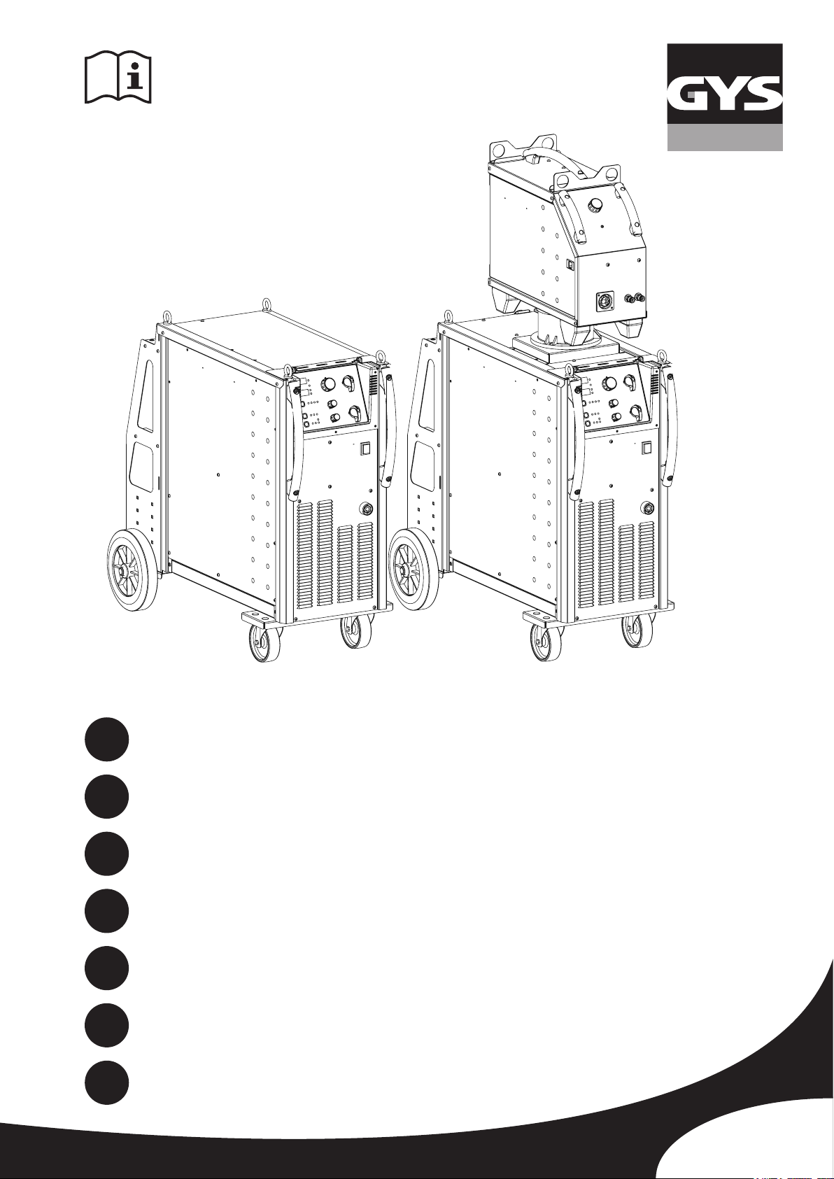
GYS MAGYS 400-4, MAGYS 400 GR, MAGYS 500 GR, MAGYS 500 WS User Manual
FR
2-3 / 4-12 / 65-75
MAGYS 400-4
EN
DE
ES
RU
IT
NL
73502-V5.1-10/12/2018
2-3 / 13-20 / 65-75
2-3 / 21-29 / 65-75
2-3 / 30-38 / 65-75
2-3 / 39-47 / 65-75
2-3 / 48-55 / 65-75
2-3 / 56-64 / 65-75
MAGYS 400 GR
MAGYS 500 GR
MAGYS 500 WS
www.gys.fr
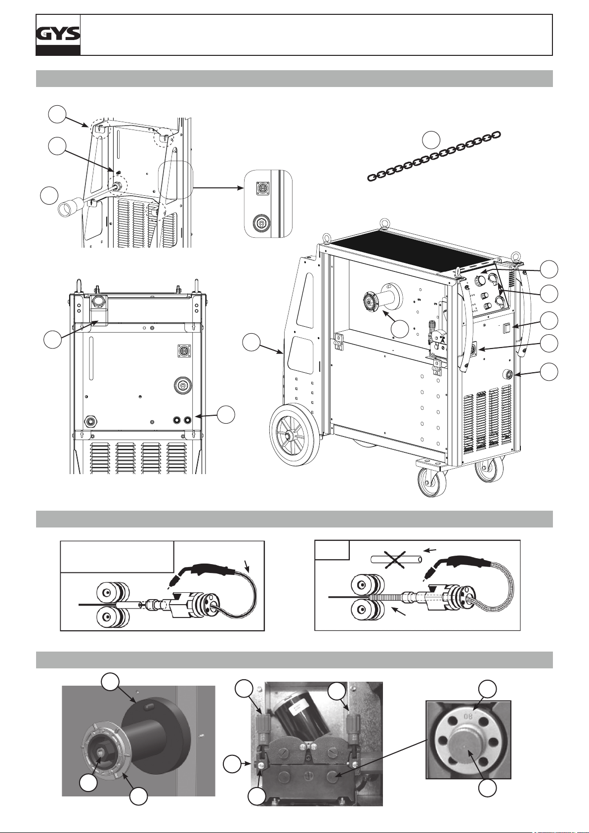
FIG - 1
13
MAGYS 400-4 / 400 GR / 500 GR / 500 WS
10
5
12
MAGYS 500 WS
MAGYS 400 GR
MAGYS 500 GR
7
11
8
MAGYS 400-4
x2
3
2
1
9
4
6
FIG - 2
- Acier / Steel / Stahl / Acero
/ Staal / Aço
- Inox - Stainless steel
A/
FIG - 3
1
2
Gaine acier / Steel
sheath / Stahlseele
8
B/
- Alu
NO USE
Gaine téon / Teon sheath
/ Teonseele
8
Tube capillaire / Capillary Pipe
/ Kapillarrohr
4
7
6
3
5
2
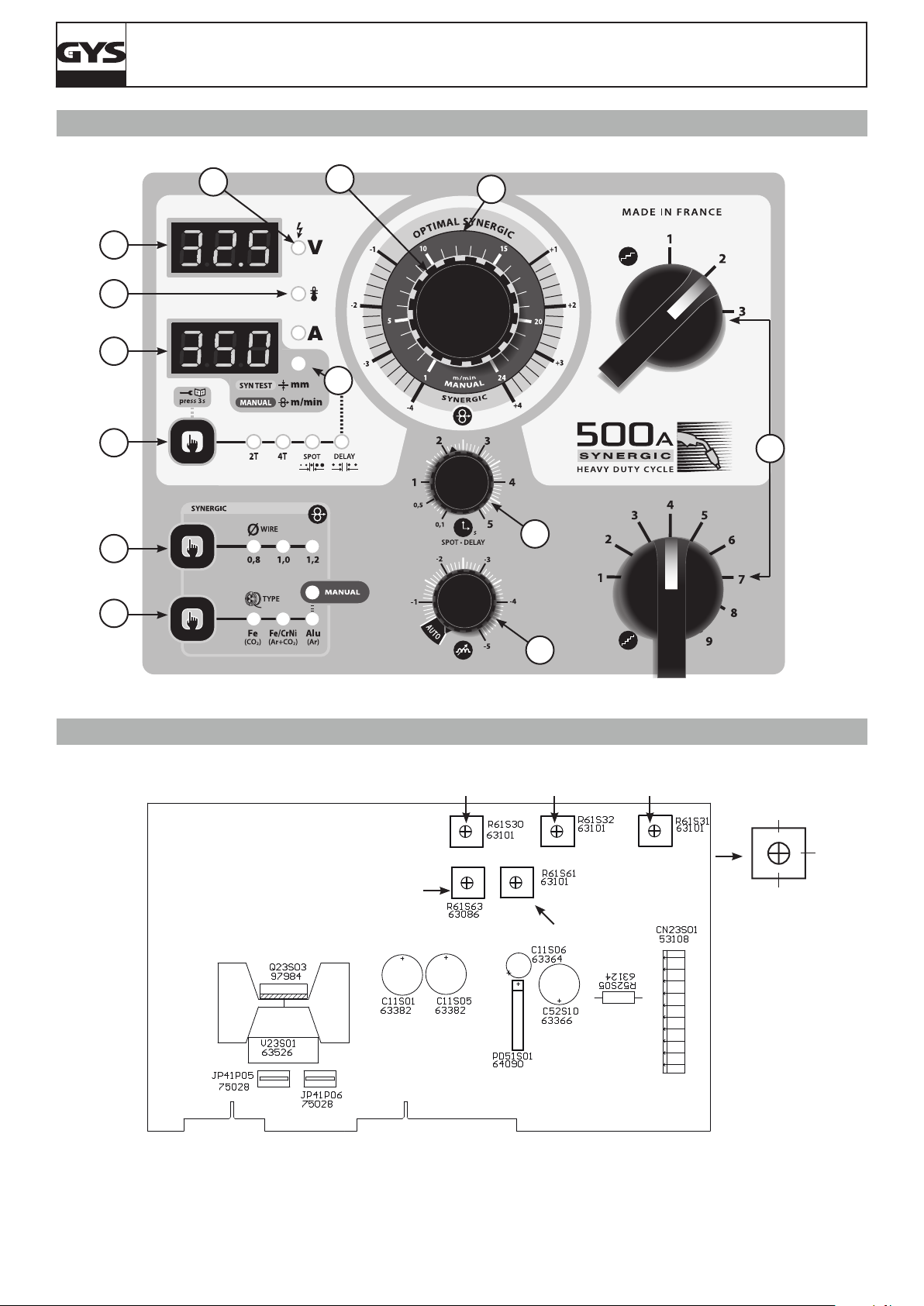
FIG - 4
MAGYS 400-4 / 400 GR / 500 GR / 500 WS
9
8
10
1
7
5
13
2
11
6
12
3
FIG - 5
P4
4
P1 P2 P3
0%
50%
100%
P5
3
MAGYS 400-4 / 400 GR / 500 GR / 500 WS
FR
AVERTISSEMENTS - RÈGLES DE SÉCURITÉ
CONSIGNE GÉNÉRALE
Ces instructions doivent être lues et bien comprises avant toute opération.
Toute modication ou maintenance non indiquée dans le manuel ne doit pas être entreprise.
Tout dommage corporel ou matériel dû à une utilisation non-conforme aux instructions de ce manuel ne pourra être retenu à la charge du fabricant.
En cas de problème ou d’incertitude, consulter une personne qualiée pour manier correctement l’installation.
ENVIRONNEMENT
Ce matériel doit être utilisé uniquement pour faire des opérations de soudage dans les limites indiquées par la plaque signalétique et/ou le manuel.
Il faut respecter les directives relatives à la sécurité. En cas d’utilisation inadéquate ou dangereuse, le fabricant ne pourra être tenu responsable.
L’installation doit être utilisée dans un local sans poussière, ni acide, ni gaz inammable ou autres substances corrosives. Il en est de même pour son
stockage. S’assurer d’une circulation d’air lors de l’utilisation.
Plages de température :
Utilisation entre -10 et +40°C (+14 et +104°F).
Stockage entre -20 et +55°C (-4 et 131°F).
Humidité de l’air :
Inférieur ou égal à 50% à 40°C (104°F).
Inférieur ou égal à 90% à 20°C (68°F).
Altitude :
Jusqu’à 1000 m au-dessus du niveau de la mer (3280 pieds).
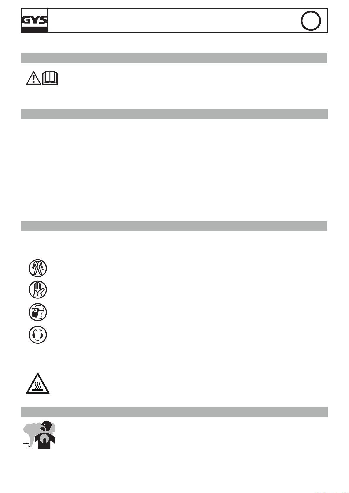
PROTECTION INDIVIDUELLE ET DES AUTRES
Le soudage à l’arc peut être dangereux et causer des blessures graves voire mortelles.
Le soudage expose les individus à une source dangereuse de chaleur, de rayonnement lumineux de l’arc, de champs électromagnétiques (attention
au porteur de pacemaker), de risque d’électrocution, de bruit et d’émanations gazeuses.
Pour bien se protéger et protéger les autres, respecter les instructions de sécurité suivantes :
An de se protéger de brûlures et rayonnements, porter des vêtements sans revers, isolants, secs, ignifugés et en bon état, qui
couvrent l’ensemble du corps.
Utiliser des gants qui garantissent l’isolation électrique et thermique.
Utiliser une protection de soudage et/ou une cagoule de soudage d’un niveau de protection sufsant (variable selon les applications).
Protéger les yeux lors des opérations de nettoyage. Les lentilles de contact sont particulièrement proscrites.
Il est parfois nécessaire de délimiter les zones par des rideaux ignifugés pour protéger la zone de soudage des rayons de l’arc, des
projections et des déchets incandescents.
Informer les personnes dans la zone de soudage de ne pas xer les rayons de l’arc ni les pièces en fusion et de porter les vêtements
adéquats pour se protéger.
Utiliser un casque contre le bruit si le procédé de soudage atteint un niveau de bruit supérieur à la limite autorisée (de même pour
toute personne étant dans la zone de soudage).
Tenir à distance des parties mobiles (ventilateur) les mains, cheveux, vêtements.
Ne jamais enlever les protections carter du groupe froid lorsque la source de courant de soudage est sous tension, le fabricant ne
pourrait être tenu pour responsable en cas d’accident.
Les pièces qui viennent d’être soudées sont chaudes et peuvent provoquer des brûlures lors de leur manipulation. Lors d’intervention
d’entretien sur la torche ou le porte-électrode, il faut s’assurer qu’il/elle soit sufsamment froid(e) en attendant au moins 10 minutes
avant toute intervention. Le groupe froid doit être allumé lors de l’utilisation d’une torche refroidie eau an d’être sûr que le liquide
ne puisse pas causer de brûlures.
Il est important de sécuriser la zone de travail avant de la quitter an de protéger les personnes et les biens.
FUMÉES DE SOUDAGE ET GAZ
Les fumées, gaz et poussières émis par le soudage sont dangereux pour la santé. Il faut prévoir une ventilation sufsante, un
apport d’air est parfois nécessaire. Un masque à air frais peut être une solution en cas d’aération insufsante.
Vérier que l’aspiration est efcace en la contrôlant par rapport aux normes de sécurité.
Attention le soudage dans les environnements réduits nécessite une surveillance à distance de sécurité. Par ailleurs le soudage de certains matériaux
contenant du plomb, cadmium, zinc ou mercure voire du béryllium peuvent être particulièrement nocifs.
Dégraisser également les pièces avant de les souder.
Les bouteilles doivent être entreposées dans des locaux ouverts ou bien aérés. Elles doivent être en position verticale et maintenues à un support ou
sur un chariot.
Le soudage doit être proscrit à proximité de graisse ou de peinture.
4
MAGYS 400-4 / 400 GR / 500 GR / 500 WS
FR
RISQUE DE FEU ET D’EXPLOSION
Protéger entièrement la zone de soudage, les matières inammables doivent être éloignées d’au moins 11 mètres.
Un équipement anti-feu doit être présent à proximité des opérations de soudage.
Attention aux projections de matières chaudes ou d’étincelles, car même à travers des ssures, elles peuvent être source
d’incendie ou d’explosion.
Éloigner les personnes, les objets inammables et les containers sous pressions à une distance de sécurité sufsante.
Le soudage dans des containers ou des tubes fermés est à proscrire et dans le cas où ils sont ouverts, il faut les vider de toute matière inammable
ou explosive (huile, carburant, résidus de gaz …).
Les opérations de meulage ne doivent pas être dirigées vers la source de courant de soudage ou vers des matières inammables.
BOUTEILLES DE GAZ
Le gaz sortant des bouteilles peut être source de suffocation en cas de concentration dans l’espace de soudage (bien ventiler).
Le transport doit être fait en toute sécurité : bouteilles fermées et la source de courant de soudage éteinte. Elles doivent être
entreposées verticalement et maintenues par un support pour limiter le risque de chute.
Fermer la bouteille entre deux utilisations. Attention aux variations de température et aux expositions au soleil.
La bouteille ne doit pas être en contact avec une amme, un arc électrique, une torche, une pince de masse ou toutes autres sources de chaleur ou
d’incandescence.
Veiller à la tenir éloignée des circuits électriques et de soudage et donc ne jamais souder une bouteille sous pression.
Attention lors de l’ouverture du robinet de la bouteille, il faut éloigner la tête la robinetterie et s’assurer que le gaz utilisé est approprié au procédé
de soudage.
SÉCURITÉ ÉLECTRIQUE
Le réseau électrique utilisé doit impérativement avoir une mise à la terre. Utiliser la taille de fusible recommandée sur le tableau
signalétique.
Une décharge électrique peut être une source d’accident grave direct ou indirect, voire mortel.
Ne jamais toucher les parties sous tension à l’intérieur comme à l’extérieur de la source de courant sous-tension (Torches, pinces, câbles, électrodes)
car celles-ci sont branchées au circuit de soudage.
Avant d’ouvrir la source de courant de soudage, il faut la déconnecter du réseau et attendre 2 minutes. an que l’ensemble des condensateurs soit
déchargé.
Ne pas toucher en même temps la torche ou le porte-électrode et la pince de masse.
Veiller à changer les câbles et torches, par des personnes qualiées et habilitées, si ceux-ci sont endommagés. Dimensionner la section des câbles
en fonction de l’application. Toujours utiliser des vêtements secs et en bon état pour s’isoler du circuit de soudage. Porter des chaussures isolantes,
quel que soit le milieu de travail.
CLASSIFICATION CEM DU MATERIEL
Ce matériel de Classe A n’est pas prévu pour être utilisé dans un site résidentiel où le courant électrique est fourni par le réseau
public d’alimentation basse tension. Il peut y avoir des difcultés potentielles pour assurer la compatibilité électromagnétique
dans ces sites, à cause des perturbations conduites, aussi bien que rayonnées à fréquence radioélectrique.
Ce matériel est conforme à la CEI 61000-3-12, à condition que la puissance de court-circuit Ssc soit supérieure ou égale à
3.9 MVA au point d’interface entre l’alimentation de l’utilisateur et le réseau public de distribution. Il est de la responsabilité de
l’installateur ou de l’utilisateur du matériel de s’assurer, si nécessaire en consultant l’exploitant du réseau de distribution, que le
matériel est raccordé uniquement à une alimentation ayant une puissance de court-circuit Ssc supérieure ou égale à 3.9 MVA.
Ce matériel est conforme à la CEI 61000-3-11.
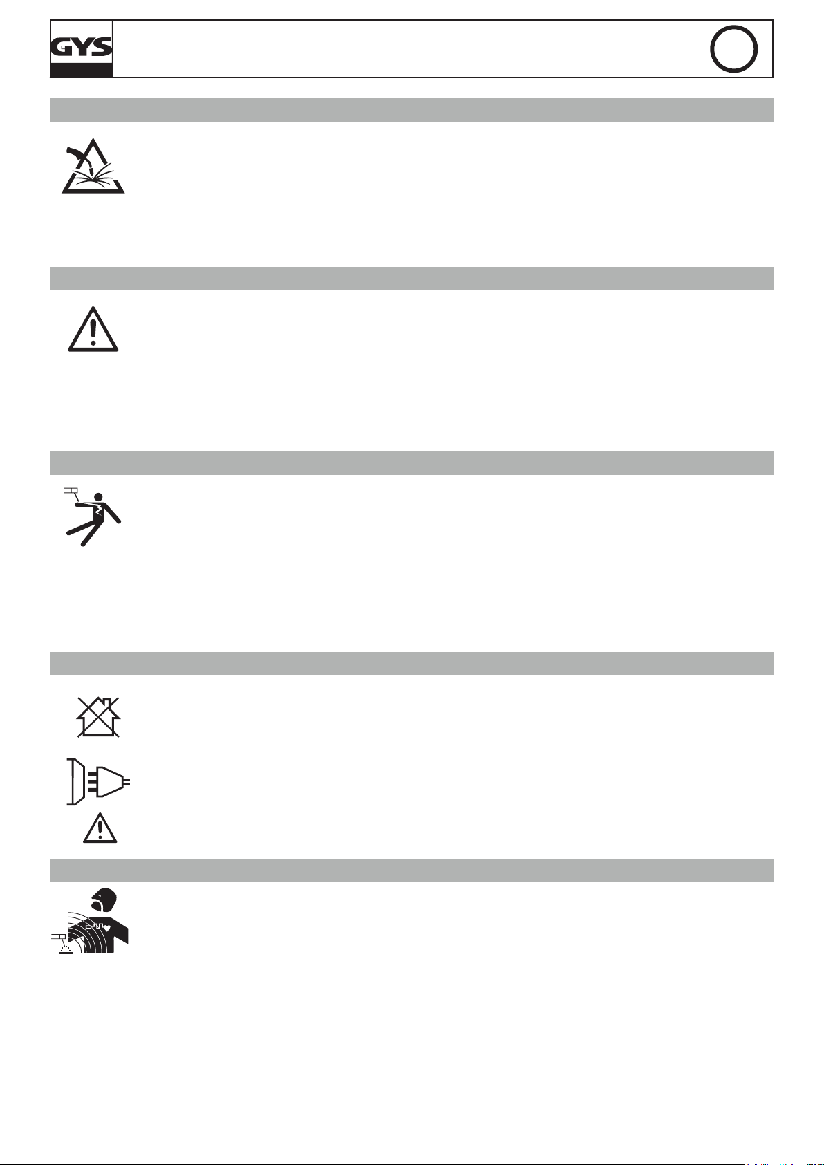
ÉMISSIONS ÉLECTROMAGNÉTIQUES
Le courant électrique passant à travers n’importe quel conducteur produit des champs électriques et magnétiques (EMF) localisés.
Le courant de soudage produit un champ électromagnétique autour du circuit de soudage et du matériel de soudage.
Les champs électromagnétiques EMF peuvent perturber certains implants médicaux, par exemple les stimulateurs cardiaques. Des mesures de
protection doivent être prises pour les personnes portant des implants médicaux. Par exemple, restrictions d’accès pour les passants ou une évaluation
de risque individuelle pour les soudeurs.
Tous les soudeurs doivent utiliser les procédures suivantes an de minimiser l’exposition aux champs électromagnétiques provenant du circuit de
soudage:
• positionner les câbles de soudage ensemble – les xer avec une attache, si possible;
• se positionner (torse et tête) aussi loin que possible du circuit de soudage;
• ne jamais enrouler les câbles de soudage autour du corps;
• ne pas positionner le corps entre les câbles de soudage. Tenir les deux câbles de soudage sur le même côté du corps;
• raccorder le câble de retour à la pièce mise en œuvre aussi proche que possible à la zone à souder;
5
MAGYS 400-4 / 400 GR / 500 GR / 500 WS
• ne pas travailler à côté de la source de courant de soudage, ne pas s’assoir dessus ou ne pas s’y adosser;
• ne pas souder lors du transport de la source de courant de soudage ou le dévidoir.
Les porteurs de stimulateurs cardiaques doivent consulter un médecin avant d’utiliser ce matériel.
L’exposition aux champs électromagnétiques lors du soudage peut avoir d’autres effets sur la santé que l’on ne connaît pas
encore.
FR
RECOMMANDATIONS POUR ÉVALUER LA ZONE ET L’INSTALLATION DE SOUDAGE
Généralités
L’utilisateur est responsable de l’installation et de l’utilisation du matériel de soudage à l’arc suivant les instructions du fabricant. Si des perturbations
électromagnétiques sont détectées, il doit être de la responsabilité de l’utilisateur du matériel de soudage à l’arc de résoudre la situation avec
l’assistance technique du fabricant. Dans certains cas, cette action corrective peut être aussi simple qu’une mise à la terre du circuit de soudage. Dans
d’autres cas, il peut être nécessaire de construire un écran électromagnétique autour de la source de courant de soudage et de la pièce entière avec
montage de ltres d’entrée. Dans tous les cas, les perturbations électromagnétiques doivent être réduites jusqu’à ce qu’elles ne soient plus gênantes.
Evaluation de la zone de soudage
Avant d’installer un matériel de soudage à l’arc, l’utilisateur doit évaluer les problèmes électromagnétiques potentiels dans la zone environnante. Ce
qui suit doit être pris en compte:
a) la présence au-dessus, au-dessous et à côté du matériel de soudage à l’arc d’autres câbles d’alimentation, de commande, de signalisation et de
téléphone;
b) des récepteurs et transmetteurs de radio et télévision;
c) des ordinateurs et autres matériels de commande;
d) du matériel critique de sécurité, par exemple, protection de matériel industriel;
e) la santé des personnes voisines, par exemple, emploi de stimulateurs cardiaques ou d’appareils contre la surdité;
f) du matériel utilisé pour l’étalonnage ou la mesure;
g) l’immunité des autres matériels présents dans l’environnement.
L’utilisateur doit s’assurer que les autres matériels utilisés dans l’environnement sont compatibles. Cela peut exiger des mesures de protection
supplémentaires;
h) l’heure du jour où le soudage ou d’autres activités sont à exécuter.
La dimension de la zone environnante à prendre en compte dépend de la structure du bâtiment et des autres activités qui s’y déroulent. La zone
environnante peut s’étendre au-delà des limites des installations.
Evaluation de l’installation de soudage
Outre l’évaluation de la zone, l’évaluation des installations de soudage à l’arc peut servir à déterminer et résoudre les cas de perturbations. Il convient
que l’évaluation des émissions comprenne des mesures in situ comme cela est spécié à l’Article 10 de la CISPR 11:2009. Les mesures in situ peuvent
également permettre de conrmer l’efcacité des mesures d’atténuation.
RECOMMANDATION SUR LES MÉTHODES DE REDUCTION DES EMISSIONS ÉLECTROMAGNÉTIQUES
a. Réseau public d’alimentation: Il convient de raccorder le matériel de soudage à l’arc au réseau public d’alimentation selon les recommandations
du fabricant. Si des interférences se produisent, il peut être nécessaire de prendre des mesures de prévention supplémentaires telles que le ltrage
du réseau public d’alimentation. Il convient d’envisager de blinder le câble d’alimentation dans un conduit métallique ou équivalent d’un matériel de
soudage à l’arc installé à demeure. Il convient d’assurer la continuité électrique du blindage sur toute sa longueur. Il convient de raccorder le blindage
à la source de courant de soudage pour assurer un bon contact électrique entre le conduit et l’enveloppe de la source de courant de soudage.
b. Maintenance du matériel de soudage à l’arc : Il convient que le matériel de soudage à l’arc soit soumis à l’entretien de routine suivant les
recommandations du fabricant. Il convient que tous les accès, portes de service et capots soient fermés et correctement verrouillés lorsque le matériel
de soudage à l’arc est en service. Il convient que le matériel de soudage à l’arc ne soit modié en aucune façon, hormis les modications et réglages
mentionnés dans les instructions du fabricant. Il convient, en particulier, que l’éclateur d’arc des dispositifs d’amorçage et de stabilisation d’arc soit
réglé et entretenu suivant les recommandations du fabricant.
c. Câbles de soudage : Il convient que les câbles soient aussi courts que possible, placés l’un près de l’autre à proximité du sol ou sur le sol.
d. Liaison équipotentielle : Il convient d’envisager la liaison de tous les objets métalliques de la zone environnante. Toutefois, des objets métalliques
reliés à la pièce à souder accroissent le risque pour l’opérateur de chocs électriques s’il touche à la fois ces éléments métalliques et l’électrode. Il
convient d’isoler l’opérateur de tels objets métalliques.
e. Mise à la terre de la pièce à souder : Lorsque la pièce à souder n’est pas reliée à la terre pour la sécurité électrique ou en raison de ses
dimensions et de son emplacement, ce qui est le cas, par exemple, des coques de navire ou des charpentes métalliques de bâtiments, une connexion
raccordant la pièce à la terre peut, dans certains cas et non systématiquement, réduire les émissions. Il convient de veiller à éviter la mise à la terre
des pièces qui pourrait accroître les risques de blessure pour les utilisateurs ou endommager d’autres matériels électriques. Si nécessaire, il convient
que le raccordement de la pièce à souder à la terre soit fait directement, mais dans certains pays n’autorisant pas cette connexion directe, il convient
que la connexion soit faite avec un condensateur approprié et choisi en fonction des réglementations nationales.
f. Protection et blindage : La protection et le blindage sélectifs d’autres câbles et matériels dans la zone environnante peuvent limiter les problèmes
de perturbation. La protection de toute la zone de soudage peut être envisagée pour des applications spéciales.
TRANSPORT ET TRANSIT DE L’APPAREIL
Ne pas utiliser les câbles ou torche pour déplacer la source de courant de soudage. Elle doit être déplacée en position verticale.
Ne pas faire transiter la source de courant au-dessus de personnes ou d’objets.
Ne jamais soulever une bouteille de gaz et la source de courant en même temps. Leurs normes de transport sont distinctes.
Il est préférable d’enlever la bobine de l avant tout levage ou transport de la source de courant de soudage.
6
MAGYS 400-4 / 400 GR / 500 GR / 500 WS
La source de tension de soudage est équipée d’une (de) poignée(s) / sangle(s) supérieure(s) permettant le portage à la main. Attention à ne pas
sous-évaluer son poids. La (les) poignée(s) / sangle(s) n’est (ne sont) pas considérée(s) comme un moyen d’élingage.
Les courants de soudage vagabonds peuvent détruire les conducteurs de terre, endommager l’équipement et les dispositifs électriques et causer des
échauffements de composants pouvant entrainer un incendie.
- Toutes les connexions de soudages doivent être connectées fermement, les vérier régulièrement !
- S’assurer que la xation de la pièce est solide et sans problèmes électriques !
- Attacher ou suspendre tous les éléments conducteurs d’électricité de la source de soudage comme le châssis, le chariot et les systèmes de levage
pour qu’ils soient isolés !
- Ne pas déposer d’autres équipements comme des perceuses, dispositifs d’affutage, etc sur la source de soudage, le chariot, ou les systèmes de
levage sans qu’ils soient isolés !
- Toujours déposer les torches de soudage ou portes électrodes sur une surface isolée quand ils ne sont pas utilisés ! »
FR
INSTALLATION DU MATÉRIEL
• Mettre la source de courant de soudage sur un sol dont l’inclinaison maximum est de 10°.
• Prévoir une zone sufsante pour aérer la source de courant de soudage et accéder aux commandes.
• La source de courant de soudage doit être à l’abri de la pluie battante et ne pas être exposée aux rayons du soleil.
• Ne pas utiliser dans un environnement comportant des poussières métalliques conductrices.
• Le matériel est de degré de protection IP23, signiant :
- une protection contre l’accès aux parties dangereuses des corps solides de Ø >12.5mm et,
- une protection contre la pluie dirigée à 60% par rapport à la verticale.
Ce matériel peut donc être utilisé à l’extérieur en accord avec l’indice de protection IP23.
• N’utilisez pas les postes à des températures > 40°C.
• Les câbles d’alimentation, de rallonge et de soudage doivent être totalement déroulés an d’éviter toute surchauffe.
Le fabricant n’assume aucune responsabilité concernant les dommages provoqués à des personnes et objets dus à une utilisation
incorrecte et dangereuse de ce matériel.
ENTRETIEN / CONSEILS
• L’entretien ne doit être effectué que par une personne qualiée. Un entretien annuel est conseillé.
• Couper l’alimentation en débranchant la prise, et attendre deux minutes avant de travailler sur le matériel. A l’intérieur, les
tensions et intensités sont élevées et dangereuses.
• Régulièrement, enlever le capot et dépoussiérer à la soufette. En proter pour faire vérier la tenue des connexions électriques avec un outil isolé
par un personnel qualié.
• Contrôler régulièrement l’état du cordon d’alimentation. Si le câble d’alimentation est endommagé, il doit être remplacé par le fabricant, son service
après-vente ou une personne de qualication similaire, an d’éviter tout danger.
• Laisser les ouïes de la source de courant de soudage libres pour l’entrée et la sortie d’air.
• Ne pas utiliser cette source de tension de soudage pour dégeler des canalisations, recharger des batteries/accumulateurs ou démarrer des moteurs.
INSTALLATION – FONCTIONNEMENT PRODUIT
Seul le personnel expérimenté et habilité par le fabricant peut effectuer l’installation. Pendant l’installation, s’assurer que le générateur est déconnecté
du réseau.
DESCRIPTION
Les Magys sont des postes de soudure semi-automatique « synergic » sur roues, ventilés pour le soudage (MIG ou MAG). Ils fonctionnent sur une
alimentation 400 V triphasée.
Pour fonctionner le générateur MAGYS :
• 400 GR doit être utilisé avec le dévidoir séparé WS-4R (ref. 034723) ou W5S-4L (réf 032835) et un faisceau de liaison.
• 500 GR doit être utilisé avec le dévidoir séparé WS-4R (ref. 034723) ou W5S-4L (réf 032835) et un faisceau de liaison.
• 500 WS doit être utilisé avec le dévidoir séparé WS-4L (ref. 033573) ou W5S-4L (réf 032835) et un faisceau de liaison.
ALIMENTATION ÉLECTRIQUE
Ce matériel est livré avec prise 32 A de type EN 60309-1 et ne doit être utilisé que sur une installation électrique triphasée 400V (50-60 Hz) à quatre
ls avec un neutre relié à la terre.
Le courant effectif absorbé (I1eff) est indiqué sur le matériel, pour les conditions d’utilisation maximales. Vérier que l’alimentation et ses protections
(fusible et/ou disjoncteur) sont compatibles avec le courant nécessaire en utilisation. Dans certains pays, il peut être nécessaire de changer la prise
pour permettre une utilisation aux conditions maximales.
• La source de puissance est prévue pour fonctionner sur une tension électrique 400V +/- 15%. Elle se met en protection si la tension d’alimentation
est inférieure à 330 Veff ou supérieure à 490Veff.
• La mise en marche se fait par rotation du commutateur marche/ arrêt (1 - FIG 1) sur la position I, inversement l’arrêt se fait par une rotation sur la
position 0. Attention ! Ne jamais couper l’alimentation lorsque le poste est en charge.
• Comportement du ventilateur : Les générateurs MAGYS 400-4 / 400 GR et 500 GR sont équipés d’une gestion intelligente de la ventilation dans le
but de minimiser le bruit du poste. La ventilation reste activée pendant 10 minutes puis s’arrête automatiquement. Si l’utilisateur appuie sur la touche
de changement de mode (1 - FIG 4), cela coupe le refroidissement immédiatement. Il sera remis en marche au cordon de soudage suivant. Même
comportement pour le MAGYS 500 WS et son système de refroidissement (groupe froid et ventilateur).
BRANCHEMENT SUR GROUPE ÉLECTROGÈNE
Le poste peut fonctionner avec des groupes électrogènes à condition que la puissance auxiliaire réponde aux exigences suivantes :
- La tension doit être alternative, sa valeur efcace doit être de 400V +/- 15%, et de tension crête inférieure à 700 V,
- La fréquence doit être comprise entre 50 et 60 Hz.
7

MAGYS 400-4 / 400 GR / 500 GR / 500 WS
Il est impératif de vérier ces conditions, car de nombreux groupes électrogènes produisent des pics de haute tension pouvant endommager les
postes.
FR
UTILISATION DE RALLONGE ÉLECTRIQUE
Toutes les rallonges doivent avoir une taille et une section appropriées à la tension de l’appareil.
Utiliser une rallonge conforme aux réglementations nationales.
Tension d’entrée Section de la rallonge (<45m)
400 V 6 mm²
MONTAGE ET DESCRIPTION DU POSTE (FIG 1)
Mettre le tapis (uniquement pour le Magys 400-4) et les 4 anneaux de levage (avec leur rondelles). La bouteille de gaz se xe à l’aide de 2 chaînes à
insérer dans les encoches prévues à cet effet. Attention : bien xer la bouteille. Il existe aussi des ouvertures pour passer des sangles (non fournies).
1- Interrupteur marche – arrêt 8- Chaines de xation pour bouteille.
2 commutateurs de réglage permettent d’ajuster
2-
la tension de soudage en sortie de générateur.
3- Clavier de réglage des paramètres de soudage. 10-
4- Raccord torche au standard européen. 11- Entrée et sortie d’eau (Magys 500 WS)
5- Câble d’alimentation (5 m) 12- Réservoir 5,5 L (Magys 500 WS)
6- Sortie pince de masse. 13- Encoches de xation pour chaînes
7- Support bouteille (bouteille de 10 m
3
max).
9- Support bobine Ø 200/300 mm.
Entrée gaz (Pour le Magys 500 WS, le tuyau gaz se raccorde directement au manomètre de la bouteille).
SOUDAGE SEMI-AUTOMATIQUE EN ACIER / INOX (MODE MAG) (FIG-2-A)
Les MAGYS sont livrés d’origine pour fonctionner avec du l Ø 1 mm en acier (galets réversible Ø 1/1,2 acier/inox). S’assurer que l’ensemble galet,
gaine, tube contact soit compatible avec le diamètre de l utilisé.
L’utilisation en acier ou inox nécessite un gaz spécique au soudage argon + CO2 (Ar + CO2) mais d’autres combinaisons sont possibles. La proportion de CO2 varie selon l’utilisation. Pour le choix du gaz, demander conseil à un distributeur de gaz. Le débit de gaz pour le soudage en acier se situe
entre 15 et 25 L/min selon les conditions de soudage.
Pour les ls de diamètre > 1.6 mm, il est recommandé de retirer le tube capillaire.
SOUDAGE SEMI-AUTOMATIQUE ALUMINIUM (FIG-2-B)
Cet appareil peut souder du l aluminium de 1 mm et plus.
Pour souder l’aluminium, il faut utiliser un gaz neutre: argon pur (Ar) mais d’autres combinaisons sont possibles. Pour le choix du gaz, demander
conseil à un distributeur de gaz. Le débit du gaz se situe entre 20 et 25 L/min selon les conditions de soudage.
- An de ne pas écraser le l, mettre un minimum sur les galets presseurs du moto-dévidoir.
- Retirer le tube capillaire avant de connecter la torche aluminium avec une gaine en téon.
- Utiliser une torche spéciale aluminium qui possède une gaine téon an de réduire les frottements.
NE PAS couper la gaine au bord du raccord ! Cette gaine sert à guider le l à partir des galets.
- Tube contact : utiliser un tube contact SPECIAL aluminium correspondant au diamètre du l.
- Utiliser des galets spéciaux pour l’aluminium.
PROCÉDURE DE MONTAGE DES BOBINES ET DES TORCHES (FIG-3)
• Positionner la bobine en tenant compte de l’ergot d’entrainement (1) du support bobine. Pour monter une bobine de Ø 200mm sur le dévidoir WS-4R
ou WS-4L, installer au préalable un adaptateur sur le support (ref. 042889).
• Régler le frein de la bobine (2) pour éviter lors de l’arrêt de la soudure que l’inertie de la bobine n’emmêle le l. Serrer ensuite fermement l’écrou
de maintien (3).
• Pour la première mise en service :
- desserrer la vis de xation du guide l (5)
- placer les galets, bien serrer leur vis de maintien (6)
- puis positionner le guide l (7) au plus près du galet mais sans contact avec ce dernier, puis resserrer la vis de xation.
• Pour régler la molette des galets presseurs (8), bloquer le l en sortie de torche, actionner le moteur. Le réglage du serrage est bon lorsque les
galets patinent sur le l même si le l est bloqué en bout de torche.
NOTA : Gâchette pressée, si le poste ne détecte pas de contact au bout de 4 secondes, il bascule sur le mode « avance rapide » jusqu’au relâchement
de la gâchette. Le gaz se coupe pendant cette opération.
ATTENTION : Pendant cette avance rapide, le l est sous tension, il faut impérativement éviter tout contact avec les pièces métalliques environ-
nantes.
RACCORDEMENT GAZ
Visser le manodétendeur sur la bouteille de gaz si besoin est, puis connecter le tuyau fourni au raccord gaz (cf (10), FIG-1 pour le MAGYS 400-4).
Pour éviter toute fuite de gaz, utiliser les colliers fournis dans la boîte d’accessoires.
REFROIDISSEMENT LIQUIDE (MAGYS 500 WS) (FIG-3) ET PROTECTION THERMIQUE
Connecter les raccords bleu & rouge du faisceau au générateur (11) et au dévidoir séparé (voir Notice WS-4L/W5S-4L)
Remplir le réservoir (12) jusqu’à son niveau maximum (5,5L de contenance). Le liquide de refroidissement recommandé par GYS (ref.
8
MAGYS 400-4 / 400 GR / 500 GR / 500 WS
052246), doit impérativement être utilisé. L’utilisation de liquides de refroidissement autres, et en particulier du liquide standard automobile, peut
conduire, par un phénomène d’électrolyse, à l’accumulation de dépôts solides dans le circuit de refroidissement, dégradant ainsi le refroidissement,
et pouvant aller jusqu’à l’obstruction du circuit.
Toute dégradation de la machine liée à l’utilisation d’un autre liquide de refroidissement ne sera pas considérée dans le cadre de la garantie.
Le MAGYS 500 WS n’est pas préconisé pour fonctionner avec une torche refroidie air.
Si malgré tout une torche air devait être utilisée, un by-pass est livré avec le poste (en face arrière). Le raccorder entre les raccords
bleu et rouge. En cas de non respect de cette consigne, la pompe sera endommagée, et cette panne ne sera pas prise en compte
dans le cadre de la garantie.
FR
Pour le MAGYS 500 WS NE JAMAIS UTILISER VOTRE POSTE SANS LIQUIDE DE REFROIDISSEMENT
lorsque la pompe est en fonctionnement. Respecter le niveau minimal (jauge face arrière)
En cas de non respect, vous risquez de détériorer de manière dénitive la pompe du système de refroidissement.
• Respecter les règles classiques du soudage.
• Laisser les ouïes de l'appareil libres pour l’entrée et la sortie d’air.
• Laisser l’appareil branché quelques minutes après soudage pour permettre le refroidissement.
• Protection thermique : Le voyant (8) Fig-4 s’allume lorsque le poste se met en sécurité. La durée de refroidissement (ventilation forcée) est par
cycles de 10 minutes en fonction de la température ambiante pour le 400-4 et à 20 minutes (ventilation forcée + pompe) pour le MAGYS 400 GR/500
GR/500 WS.
• Ventilation : La ventilation n’est active que lors du soudage et par cycles de refroidissement.
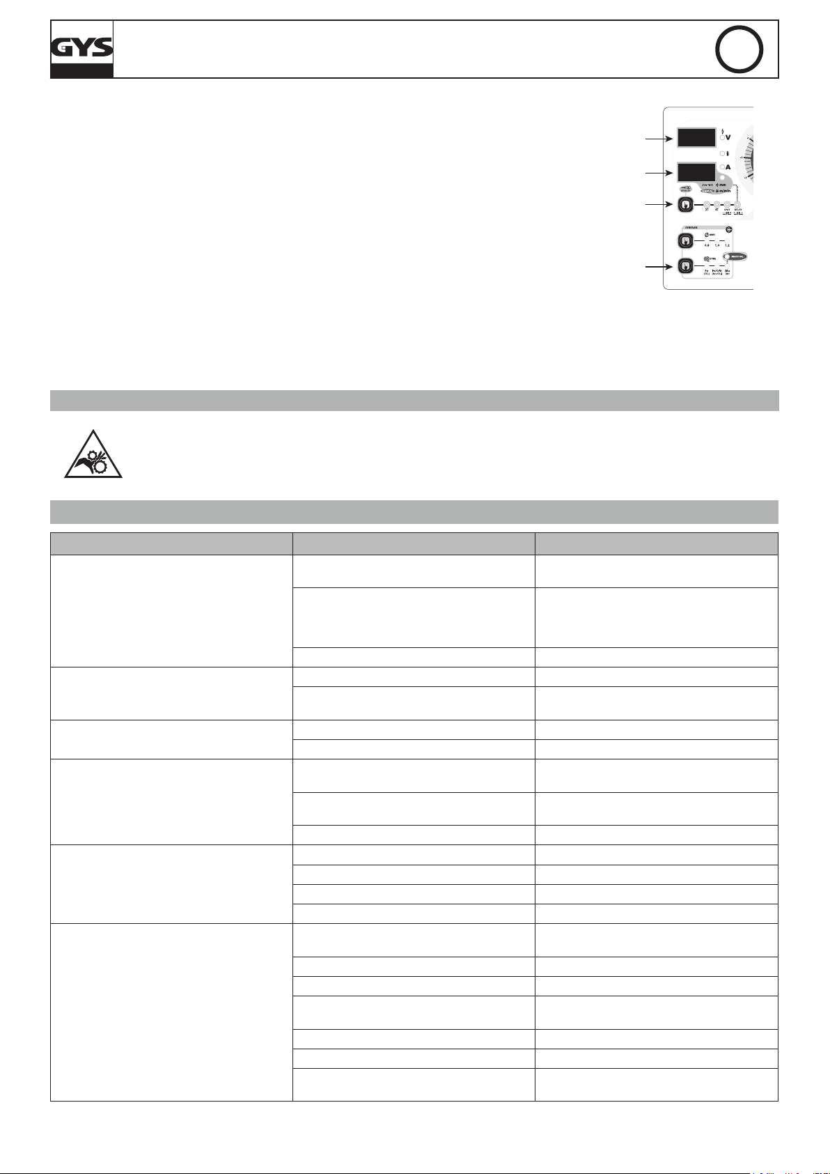
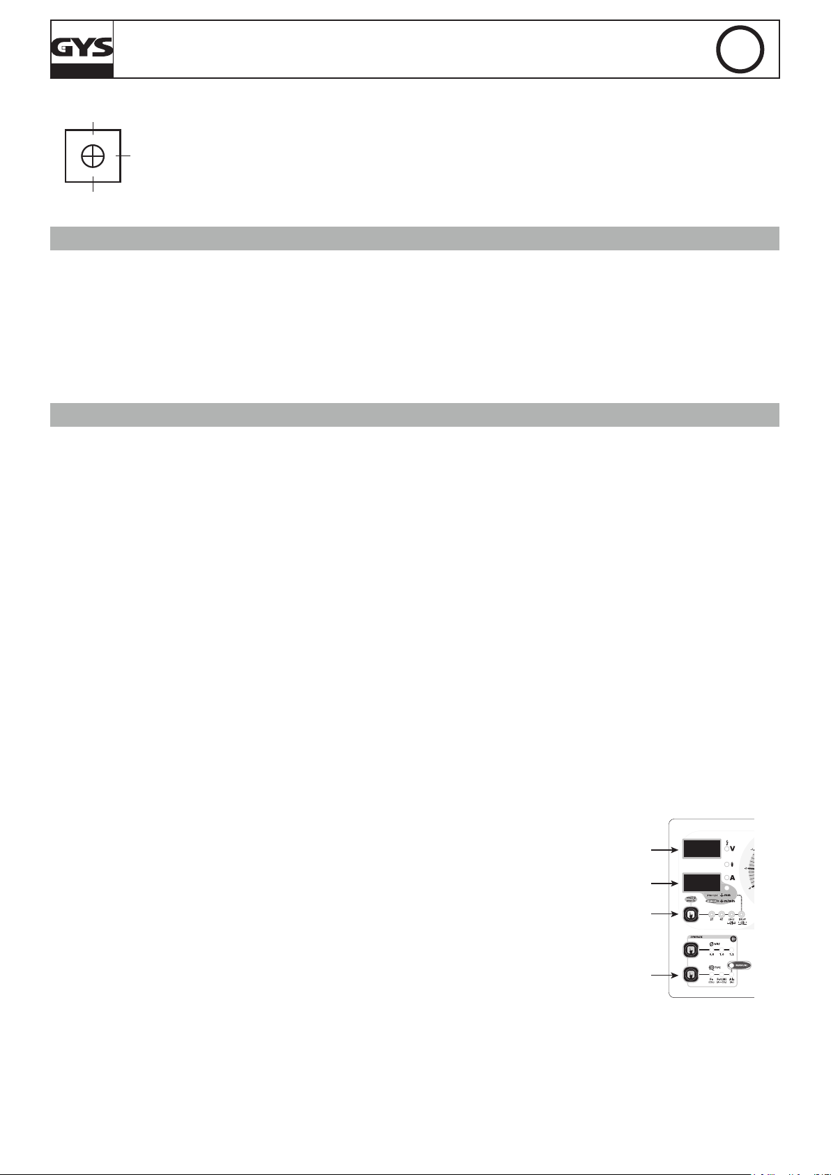
CLAVIER DE COMMANDE (FIG-4)
Choix du mode de soudage / test :
-2T : soudage 2 temps / 4T : soudage 4 temps.
-SPOT : fonction bouchonnage / spot avec réglage du diamètre du
point.
-Delay : Fonction « point de chainette »
2 modes sont proposés pour faciliter le réglage du poste:
« Manual » ou « Synergic ».
1
- Fonction test : Le voyant s’allume Via l’appui sur la touche (1).
Voir description au chapitre « réglage du poste »
Accès au mode caché et paramétrage du mode Expert
(voir page suivante)
Afcheur tension : L’appui sur la gâchette (Le voyant
9
indique que la torche est sous tension) afche la valeur de la
tension du réglage en cours.
Commutateurs : 20 positions pour le Magys 400-4 et 400 GR
12
et 30 pour le 500 GR / 500 WS.
Potentiomètre de réglage SPOT / DELAY : Fait varier la durée
3
du point, la taille du point et l’intervalle entre chaque point.
Potentiomètre de la dynamique d’arc : Permet d’ajuster en
4
auto ou manuellement la dynamique d’arc.
Choix matière et mode Manuel : Voir chapitre « réglage du
5
poste »
Mode « Synergic » : Voir chapitre « réglage du poste »
6
Diamètre de l : Sélection du diamètre de l.
7
Voyant de protection thermique : Voir chapitre
8
« conseils et protection thermique ».
Réglage de la vitesse l : Potentiomètre d’ajustage de la
vitesse du l. La vitesse varie de 1 à 24 m/minute.
Nota pour le MAGYS 400 GR / 500 GR / 500 WS : Il est possible de sélectionner le potentiomètre du dévidoir déporté ou
2
du générateur.
Voir chapitre « sélection du potentiomètre de vitesse l » et
l’autocollant à l’intérieur du dévidoir.
Afcheur intensité 10 : Afche l’intensité (voyant « A
») ou l’épaisseur 11 préconisée en fonction de la puissance
sélectionnée (voir fonction « test » au chapitre « réglage du
10
poste »).
Nota : L’information « NOP » indique que la tension choisie
11
est supérieure à celle préconisée pour la matière sélectionnée
et le diamètre de l.
RÉGLAGES DU POSTE (FIG-4)
MODE « SYNERGIC »
Grâce à cette fonction, plus besoin de régler la vitesse l.
- Positionner le potentiomètre (2) vitesse l au milieu de la zone « Optimal synergic »
- Sélectionner : La nature du l (5), le diamètre du l (7), la tension de soudage (Par les 2 commutateurs en face avant (12)).
A partir de cette combinaison de paramètres, cet appareil détermine la vitesse de l optimale et le poste est prêt à souder. Il est ensuite possible
d’ajuster la vitesse l si nécessaire en + ou en – grâce au potentiomètre (2). Une mémorisation des dernières congurations de soudage est effectuée
et réactivée à chaque mise en route du poste (diamètre l, nature l, mode).
Fonction « test »
Uniquement en mode synergique, permet d’avoir une épaisseur indicative soudable en fonction des paramètres sélectionnés sans consommer de gaz ni de l. Ces valeurs sont calculées sur la base d’un soudage en angle à plat. Attention : la
torche est sous tension, éviter tout contact.
NOTA : Si le gaz, le diamètre de l, le type de métal utilisés sont différents de ceux indiqués en mode synergique, il faut alors passer par le mode
manuel pour régler le poste.
9
MAGYS 400-4 / 400 GR / 500 GR / 500 WS
0%
100%
réglage
FR
MODE «MANUAL»
Pour régler votre poste procéder comme suit :
- En fonction de l’épaisseur à souder, choisissez la tension de soudage à l’aide des 2 commutateurs
- Ajustez la vitesse du l à l’aide du potentiomètre (2).
Uniquement en mode manuel, cette fonction permet de visualiser précisément le réglage de la vitesse l sur l’afcheur
(10).
MODIFICATION DES PARAMÈTRES D’USINE (FIG-5)
L’appareil contrôle la vitesse d’accostage, le burn back et le post gaz. Ces paramètres sont réglés en usine, il est tout de fois possible de les modier
directement sur la carte électronique. Attention : cette intervention doit être faite par un électricien qualié.
IMPORTANT : Veuillez débrancher l’appareil avant toute intervention.
P1 : Réglage de la vitesse d’accostage permet une approche plus douce an d’éviter les éclaboussures aux premiers
courts-circuits.
50%
usine
P2 : Réglage du Burn back. Cette fonction permet d’éviter au l de venir se coller au tube contact en n de cordon.
P3 : Réglage du Post gaz. Réglage du temps pendant lequel le gaz continu de protéger le bain de fusion à la n du
cordon.
PARAMÉTRAGE EXPERT (SELON NORME EN 1090)
An de satisfaire aux exigences de la norme EN 1090, il est possible d’étalonner la tension, le courant et la vitesse l de l’appareil. Attention : l’étalonnage doit se faire par GYS ou le distributeur s’il possède un service de maintenance qualié. Équipements nécessaires : Charge résistive (réf :
060135), tachymètre (réf : 053953), voltmètre et ampèremètre (réf : 053984).
1/ Étalonnage de la tension et du courant (FIG-5) :
Les potentiomètres P4 (tension) et P5 (courant) sont réglables directement sur la carte électronique.
2/ Étalonnage de la vitesse l (FIG-4) :
L’accès à ce mode se fait par appui long sur la touche (1) pendant 3 sec. Ensuite, appuyer 3 fois sur la touche 1 an que l’afcheur indique « Fc3 ».
Vous pouvez maintenant étalonner votre vitesse l à +/- 10% par pas de 1% grâce aux touches (5) et (7). Pour sortir du mode, appuyer sur la touche
(1), l’afcheur indique « END ».
MODE CACHÉ (FIG-4)
Le mode caché permet d’atteindre les fonctions suivantes :
• le mode gougeage (Magys 500 GR / 500 WS) «Fc0»
• sélection du potentiomètre de vitesse l (uniquement pour le Magys 400 GR / 500 GR / 500 WS) «Fc1»
• autorisation/interdiction des matériaux «Fc2»
• étalonnage de la vitesse l (voir ci-dessus : paramétrages expert) «Fc3»
L’accès à ce mode se fait par appui maintenu sur la touche (1) pendant 3 sec. L’afcheur indique « Fc0 » , « OFF ». Appuyer de nouveau sur la touche
(1) pour entrer dans le mode Gougeage.
Mode gougeage : (Magys 500 GR / 500 WS) (Fc0)
L’afcheur du haut indique « Arc », « Air » et l’afcheur du bas indique « OFF ».
Pour activer le générateur de courant, appuyer sur la touche 5. L’afcheur indique alors « Arc », « Air », « On ».
ATTENTION : une fois le générateur de courant activé, la puissance en sortie d’appareil est disponible. Ne pas poser la torche au sol, en contact avec
un matériau métallique, utiliser des équipements de protections, …
Pour désactiver le générateur de courant appuyer sur la touche 5. Pour sortir du mode gougeage, il faut appuyer sur la touche 1. Cette sortie implique
une sortie du mode caché, l’afcheur indique « END ».
Procédure du gougeage :
- Mettre le commutateur à pleine puissance,
- ouvrir le robinet d’air,
- le contact entre l’électrode et la pièce provoque un court-circuit. Un bain de fusion est immédiatement produit et l’air canalisé par la torche projette
le métal en fusion du bain.
- l’avance du travail se fait en poussant, à l’inverse du MMA.
Pour une utilisation optimale il faut toujours laisser 100 – 150 mm entre le bout de l’électrode et la pince de gougeage.
La torche se connecte au générateur à l’arrière du produit, pôle + pour des électrodes acier, inox. Pour des électrodes en cuivre se connecter à
n’importe quel pôle. Pour une électrode Nickel se connecter au pôle -. La pince de masse se branche de la même manière que pour le soudage.
Il est important de respecter les indications notées sur les boîtes d’électrodes utilisées.
Cette manipulation requiert un EPI obligatoire !
10
MAGYS 400-4 / 400 GR / 500 GR / 500 WS
FR
Sélection du potentiomètre de vitesse l (Magys 400 GR / 500 GR / 500 WS) : (Fc1)
Le réglage de la vitesse l peut se faire soit avec le potentiomètre du dévidoir, soit avec celui du
générateur. Les 2 ne peuvent pas être actifs en même temps.
Pour entrer dans le mode « Sélection du potentiomètre de vitesse l » appuyer 3 sec sur la touche
(1) et à nouveau sur cette touche. L’afcheur du haut indique « Fc1 » et l’afcheur du bas indique:
- « Out » pour le potentiomètre du dévidoir
- « In » pour le potentiomètre du générateur
Pour passer de Out à In, il suft d’appuyer sur la touche (5) dont les voyants clignotent. En appuyant
sur la touche (1) vous sortirez de cette fonction et passerez à la fonction « Autorisation/Interdiction
des matériaux »
FC1 s’affiche
In / Out
s’affiche
(1) 3 sec
(5) Permet de
sélectionner le
potentiomètre
Autorisation/interdiction des matériaux : (Fc2)
Il est possible d’autoriser ou non l’utilisation des 3 choix de matériaux (Fe CO², FeCrNi ArCO², Aluminium). Pour entrer dans ce mode il suft d’entrer
dans le mode caché et d’appuyer 2 fois sur la touche 1. L’afcheur indique « Fc2 ». An de choisir votre combinaison de matériaux (8 possibilités), il
suft d’appuyer sur la touche 5 jusqu’à obtenir ce que vous souhaitez. La position « Manual » ne peut être désactivée.
Pour sortir du mode caché appuyer sur la touche 1, l’afcheur indique « END ».
RISQUE DE BLESSURE LIÉ AUX COMPOSANTS MOBILES
Les dévidoirs sont pourvus de composants mobiles qui peuvent happer les mains, les cheveux, les vêtements ou les outils et
entraîner par conséquent des blessures !
• Ne pas porter la main aux composants pivotants ou mobiles ou encore aux pièces d’entraînement!
• Veiller à ce que les couvercles du carter ou couvercles de protection restent bien fermés pendant le fonctionnement !
• Ne pas porter de gants lors de l’enlement du l d’apport et du changement de la bobine du l d’apport.
ANOMALIES, CAUSES, REMÈDES
SYMPTÔMES CAUSES REMÈDES
Le débit du l de soudage n’est pas constant.
Le moteur de dévidage ne fonctionne pas.
Mauvais dévidage du l.
Pas de courant de soudage.
Le l bouchonne après les galets.
Le cordon de soudage est poreux.
Des grattons obstruent l’orice.
Le l patine dans les galets.
Un des galets patine Vérier le serrage de la vis du galet.
Frein de la bobine ou galet trop serré. Desserrer le frein et les galets
Problème d’alimentation
Gaine guide l sale ou endommagée. Nettoyer ou remplacer.
Frein de la bobine trop serré. Desserrer le frein.
Mauvais branchement de la prise secteur.
Mauvaise connexion de masse.
Contacteur de puissance inopérant. Contrôler la gâchette de la torche.
Gaine guide l écrasée. Vérier la gaine et corps de torche.
Blocage du l dans la torche. Remplacer ou nettoyer.
Pas de tube capillaire. Vérier la présence du tube capillaire.
Vitesse du l trop importante. Réduire la vitesse de l
Le débit de gaz est insufsant.
Bouteille de gaz vide. La remplacer.
Qualité du gaz non satisfaisante. Le remplacer.
Circulation d’air ou inuence du vent.
Buse gaz trop encrassée. Nettoyer la buse gaz ou la remplacer.
Mauvaise qualité du l. Utiliser un l adapté au soudage MIG-MAG.
État de la surface à souder de mauvaise qualité
(rouille, etc…)
Nettoyer le tube contact ou le changer et remettre du produit anti-adhésion.
- Contrôler la pression des galets ou les remplacer.
- Diamètre du l non conforme au galet.
-Gaine guide l dans la torche non conforme.
Vérier que le bouton de mise en service est
sur la position marche.
Voir le branchement de la prise et regarder si la
prise est bien alimentée avec 3 phases.
Contrôler le câble de masse (connexion et état
de la pince).
Plage de réglage de 15 à 25 L / min.
Nettoyer le métal de base.
Empêcher les courants d’air, protéger la zone
de soudage.
Nettoyer la pièce avant de souder
11

MAGYS 400-4 / 400 GR / 500 GR / 500 WS
FR
Particules d’étincelage
très importantes.
Pas de gaz en sortie de torche Mauvaise connexion du gaz
À la mise sous tension :
l’afcheur (9) indique « Err » et l’afcheur (10)
indique « 002 ».
À la mise sous tension :
l’afcheur (9) indique « Err » et l’afcheur (10)
indique « 001 ».
Le gaz n’est pas connecté
Tension d’arc trop basse ou trop haute. Voir paramètres de soudage.
Mauvaise prise de masse.
Au moins une des 3 touches du clavier
enfoncée.
La gâchette de la torche est enfoncée. La gâchette doit être relâchée.
Vérier que le gaz est connecté à l’entrée géné-
rateur.
Contrôler et positionner la pince de masse au
plus proche de la zone à souder
Vérier le branchement des entrées de gaz
Vérier que l’électrovanne fonctionne
est
Les 3 touches
doivent être relâchées.
CONDITIONS DE GARANTIE FRANCE
La garantie couvre tous défauts ou vices de fabrication pendant 2 ans, à compter de la date d’achat (pièces et main d’oeuvre).
La garantie ne couvre pas :
• Toutes autres avaries dues au transport.
• L’usure normale des pièces (Ex. : câbles, pinces, etc.).
• Les incidents dus à un mauvais usage (erreur d’alimentation, chute, démontage).
• Les pannes liées à l’environnement (pollution, rouille, poussière).
En cas de panne, retourner l’appareil à votre distributeur, en y joignant :
- un justicatif d’achat daté (ticket de sortie de caisse, facture….)
- une note explicative de la panne.
12
MAGYS 400-4 / 400 GR / 500 GR / 500 WS
EN
WARNING - SAFETY RULES
GENERAL INSTRUCTIONS
Read and understand the following safety recommendations before using or servicing the unit.
Any change or servicing that is not specied in the instruction manual must not be undertaken.
The manufacturer is not liable for any injury or damage caused due to non-compliance with the instructions featured in this manual .
In the event of problems or uncertainties, please consult a qualied person to handle the installation properly.
ENVIRONMENT
This equipment must only be used for welding operations in accordance with the limits indicated on the descriptive panel and/or in the user manual.
The operator must respect the safety precautions that apply to this type of welding. In case of inedaquate or unsafe use, the manufacturer cannot
be held liable for damage or injury.
This equipment must be used and stored in a place protected from dust, acid or any other corrosive agent. Operate the machine in an open, or
well-ventilated area.
Operating temperature:
Use between -10 and +40°C (+14 and +104°F).
Store between -20 and +55°C (-4 and 131°F).
Air humidity:
Lower or equal to 50% at 40°C (104°F).
Lower or equal to 90% at 20°C (68°F).
Altitude:
Up to 1000 meters above sea level (3280 feet).
PROTECTION OF THE INDIVIDUALS
Arc welding can be dangerous and can cause serious and even fatal injuries.
Welding exposes the user to dangerous heat, arc rays, electromagnetic elds, noise, gas fumes, and electrical shocks. People wearing pacemakers
are advised to consult with their doctor before using this device.
To protect oneself as well as the other, ensure the following safety precautions are taken:
In order to protect you from burns and radiations, wear clothing without cuffs. These clothes must be insulated, dry, reproof and
in good condition, and cover the whole body.
Wear protective gloves which guarantee electrical and thermal insulation.
Use sufcient welding protective gear for the whole body: hood, gloves, jacket, trousers... (varies depending on the application/
operation). Protect the eyes during cleaning operations. Do not operate whilst wearing contact lenses.
It may be necessary to install reproof welding curtains to protect the area against arc rays, weld spatters and sparks.
Inform the people around the working area to never look at the arc nor the molten metal, and to wear protective clothes.
Ensure ear protection is worn by the operator if the work exceeds the authorised noise limit (the same applies to any person in the
welding area).
Stay away from moving parts (e.g. engine, fan...) with hands, hair, clothes etc.
Never remove the safety covers from the cooling unit when the machine is plugged in - The manufacturer is not responsible for any
accident or injury that happens as a result of not following these safety precautions.
The pieces that have just been welded are hot and may cause burns when manipulated. During maintenance work on the torch or
the electrode holder, you should make sure it’s cold enough and wait at least 10 minutes before any intervention. The cooling unit
must be on when using a water cooled torch in order to ensure that the liquid does not cause any burns.
ALWAYS ensure the working area is left as safe and secure as possible to prevent damage or accidents.
WELDING FUMES AND GAS
The fumes, gases and dust produced during welding are hazardous. It is mandatory to ensure adequate ventilation and/or
extraction to keep fumes and gases away from the work area. An air fed helmet is recommended in cases of insufcient air supply
in the workplace.
Check that the air intake is in compliance with safety standards.
Care must be taken when welding in small areas, and the operator will need supervision from a safe distance. Welding certain pieces of metal
containing lead, cadmium, zinc, mercury or beryllium can be extremely toxic. The user will also need to degrease the workpiece before welding.
Gas cylinders must be stored in an open or ventilated area. The cylinders must be in a vertical position secured to a support or trolley.
Do not weld in areas where grease or paint are stored.
13
MAGYS 400-4 / 400 GR / 500 GR / 500 WS
EN
FIRE AND EXPLOSION RISKS
Protect the entire welding area. Compressed gas containers and other inammable material must be moved to a minimum safe
distance of 11 meters. A re extinguisher must be readily available.
Be careful of spatter and sparks, even through cracks. It can be the source of a re or an explosion.
Keep people, ammable objects and containers under pressure at a safe distance.
Welding of sealed containers or closed pipes should not be undertaken, and if opened, the operator must remove any inammable or explosive
materials (oil, petrol, gas...).
Grinding operations should not be directed towards the device itself, the power supply or any ammable materials.
GAS BOTTLE
Gas leaking from the cylinder can lead to suffocation if present in high concentrations around the work area.
Transport must be done safely: Cylinders closed and product off. Always keep cylinders in an upright position securely chained to
a xed support or trolley. Close the bottle after any welding operation. Be wary of temperature changes or exposure to sunlight.
Close the bottle after any welding operation. Be wary of temperature changes or exposure to sunlight.
Cylinders should be located away from areas where they may be struck or subjected to physical damage.
Always keep gas bottles at a safe distance from arc welding or cutting operations, and any source of heat, sparks or ames.
Be careful when opening the valve on the gas bottle, it is necessary to remove the tip of the valve and make sure the gas meets your welding
requirements.
ELECTRIC SAFETY
The machine must be connected to an earthed electrical supply. Use the recommended fuse size.
An electrical discharge can directly or indirectly cause serious or deadly accidents .
Do not touch any live part of the machine (inside or outside) when it is plugged in (Torches, earth cable, cables, electrodes) because they are
connected to the welding circuit.
Before opening the device, it is imperative to disconnect it from the mains and wait 2 minutes, so that all the capacitors are discharged.
Do not touch the torch or electrode holder and earth clamp at the same time.
Damaged cables and torches must be changed by a qualied and skilled professional. Make sure that the cable cross section is adequate with the
usage (extensions and welding cables). Always wear dry clothes in good condition, in order to be insulated from the electrical circuit. Wear insulating
shoes, regardless of the environment in which you work in.
EMC CLASSIFICATION
These Class A devices are not intended to be used on a residential site where the electric current is supplied by the public
network, with a low voltage power supply. There may be potential difculties in ensuring electromagnetic compatibility on these
sites, because of the interferences, as well as radio frequencies.
This equipment complies with IEC 61000-3-12, provided that the power of the short-circuit Ssc is equal to or greater than 3.9
MVA at the interface between the machine and the mains power network. It is the responsibility of the installer or user of the
equipment to ensure if necessary by consulting the operator of the mains electricity, that the equipment is only connected to a
power supply where the power of short-circuit ssc is equal to or greater than 3.9 MVA.
This equipment complies with the IEC 61000-3-11 standard.
ELECTROMAGNETIC INTERFERENCES
The electric currents owing through a conductor cause electrical and magnetic elds (EMF). The welding current generates an EMF
eld around the welding circuit and the welding equipment.
The EMF elds may disrupt some medical implants, such as pacemakers. Protection measures should be taken for people wearing medical implants.
For example, access restrictions for passers-by or an individual risk evaluation for the welders.
All welders should take the following precautions in order to minimise exposure to the electromagnetic elds (EMF) generated by the welding circuit::
• position the welding cables together – if possible, attach them;
• keep your head and torso as far as possible from the welding circuit;
• never enroll the cables around your body;
• never position your body between the welding cables. Hold both welding cables on the same side of your body;
• connect the earth clamp as close as possible to the area being welded;
• do not work too close to, do not lean and do not sit on the welding machine
• do not weld when you’re carrying the welding machine or its wire feeder.
14
MAGYS 400-4 / 400 GR / 500 GR / 500 WS
People wearing pacemakers are advised to consult their doctor before using this device.
Exposure to electromagnetic elds while welding may have other health effects which are not yet known.
EN
RECOMMANDATIONS TO ASSES THE AREA AND WELDING INSTALLATION
Overview
The user is responsible for installing and using the arc welding equipment in accordance with the manufacturer’s instructions. If electromagnetic
disturbances are detected, it is the responsibility of the user of the arc welding equipment to resolve the situation with the manufacturer’s technical
assistance. In some cases, this remedial action may be as simple as earthing the welding circuit. In other cases, it may be necessary to construct an
electromagnetic shield around the welding power source and around the entire piece by tting input lters. In all cases, electromagnetic interferences
must be reduced until they are no longer bothersome.
Welding area assessment
Before installing the machine, the user must evaluate the possible electromagnetic problems that may arise in the area where the installation is
planned.
. In particular, it should consider the following:
a) the presence of other power cables (power supply cables, telephone cables, command cable, etc...)above, below and on the sides of the arc
welding machine.
b) television transmitters and receivers ;
c) computers and other hardware;
d) critical safety equipment such as industrial machine protections;
e) the health and safety of the people in the area such as people with pacemakers or hearing aids;
f) calibration and measuring equipment
g)The isolation of the equipment from other machinery.
The user will have to make sure that the devices and equipments that are in the same room are compatible with each other. This may require extra
precautions;
h) make sure of the exact hour when the welding and/or other operations will take place.
The surface of the area to be considered around the device depends on the the building’s structure and other activities that take place there. The area
taken in consideration can be larger than the limits determined by the companies.
Welding area assessment
Besides the welding area, the assessment of the arc welding systems intallation itself can be used to identify and resolve cases of disturbances. The
assessment of emissions must include in situ measurements as specied in Article 10 of CISPR 11: 2009. In situ measurements can also be used to
conrm the effectiveness of mitigation measures.
RECOMMENDATION ON METHODS OF ELECTROMAGNETIC EMISSIONS REDUCTION
a. National power grid: The arc welding machine must be connected to the national power grid in accordance with the manufacturer’s
recommendation. If interferences occur, it may be necessary to take additional preventive measures such as the ltering of the power suplly network.
Consideration should be given to shielding the power supply cable in a metal conduit. It is necessary to ensure the shielding’s electrical continuity
along the cable’s entire length. The shielding should be connected to the welding current’s source to ensure good electrical contact between the
conduct and the casing of the welding current source.
b. Maintenance of the arc welding equipment: The arc welding machine should be be submitted to a routine maintenance check according to
the manufacturer’s recommendations. All accesses, service doors and covers should be closed and properly locked when the arc welding equipment
is on.. The arc welding equipment must not be modied in any way, except for the changes and settings outlined in the manufacturer’s instructions.
The spark gap of the arc start and arc stabilization devices must be adjusted and maintained according to the manufacturer’s recommendations.
c. Welding cables: Cables must be as short as possible, close to each other and close to the ground, if not on the ground.
d. Electrical bonding : consideration shoud be given to bonding all metal objects in the surrounding area. However, metal objects connected to
the workpiece increase the riskof electric shock if the operator touches both these metal elements and the electrode. It is necessary to insulate the
operator from such metal objects.
e. Earthing of the welded part : When the part is not earthed - due to electrical safety reasons or because of its size and its location (which is the
case with ship hulls or metallic building structures), the earthing of the part can, in some cases but not systematically, reduce emissions It is preferable
to avoid the earthing of parts that could increase the risk of injury to the users or damage other electrical equipment. If necessary, it is appropriate
that the earthing of the part is done directly, but in some countries that do not allow such a direct connection, it is appropriate that the connection is
made with a capacitor selected according to national regulations.
f. Protection and plating : The selective protection and plating of other cables and devices in the area can reduce perturbation issues. The
protection of the entire welding area can be considered for specic situations.
TRANSPORT AND TRANSIT OF THE WELDING MACHINE
Do not use the cables or torch to move the machine. The welding equipment must be moved in an upright position.
Do not place/carry the unit over people or objects.
Never lift the machine while there is a gas cylinder on the support shelf. A clear path is available when moving the item.
The removal of the wire reel from the machine is recommended before undertaking any lifting operation.
The machine is tted with handle(s) to facilitate transportation. Be careful not to underestimate the machine’s weight. The handle(s) cannot be used
for slinging.
Stray welding currents/voltages may destroy earth conductors, damage electrical equipment or cause components to warm up which may cause a re.
• All welding connections must be rmly secured, check regularly !
• Check that the metal piece xation is strong and without any electrical problems !
• Attach or hang all the electrically conductive elements, such as the trolley and slinging equipment, in order to insulate them
• Do not place any electrical equipment, such as drills or grinders, on top of the welding machine without insulating them !
• Always place welding torches or electrodes holders on an insulated surface when they’re not in use !
15
MAGYS 400-4 / 400 GR / 500 GR / 500 WS
EN
EQUIPMENT INSTALLATION
• Put the machine on the oor (maximum incline of 10°.)
• Ensure the work area has sufcient ventillation for welding, and that there is easy access to the control panel.
• The machine must be placed in a sheltered area away from rain or direct sunlight.
• The machine must not be used in an area with conductive metal dusts.
• The machine protection level is IP23, which means :
- Protection against acess to dangerous parts from solid bodies of a ≥12.5mm diameter and,
- Protection against the rain inclined at 60% towards the vertical.
These devices can be used outside in accordance with the IP23 protection index.
• Do not use the machine at temperatures > 40°C.
The power cables, extensions and welding cables must be fully uncoiled to prevent overheating.
The manufacturer does not incur any responsability regarding damages to both objects and persons that result from an incorrect
and/or dangerous use of the machine .
MAINTENANCE / RECOMMENDATIONS
• Maintenance should only be carried out by a qualied person. Annual maintenance is recommended.
• Ensure the machine is unplugged from the mains, and wait for two minutes before carrying out maintenance work. DANGER
High Voltage and Currents inside the machine.
• Remove the casing 2 or 3 times a year to remove any excess dust. Take this opportunity to have the electrical connections checked by a qualied
person, with an insulated tool.
• Regularly check the condition of the power supply cable. If the power cable is damaged, it must be replaced by the manufacturer, its after sales
service or an equally qualied person.
• Ensure the ventilation holes of the device are not blocked to allow adequate air circulation.
• Do not use this equipment to thaw pipes, to charge batteries, or to start any engine.
INSTALLATION – PRODUCT OPERATION
Only qualied personnel authorised by the manufacturer should perform the installation of the welding equipment. During the installation, the
operator must ensure that the machine is disconnected from the mains.
DESCRIPTION
Magys are «synergic» semi-automatic welding units on wheels, ventilated for welding (MIG or MAG). They operate on a three-phase 400 V power
supply.
To operate, the MAGYS:
• 400 GR must be used with the external wire feeder WS-4R (ref. 034723) or W5S-4L (ref 032835) and an interconnect cable.
• 500 GR must be used with the external wire feeder WS-4R (ref. 034723) or W5S-4L (ref 032835) and an interconnect cable.
• 500 WS must be used with the external wire feeder WS-4L (ref. 033573) or W5S-4L (ref 032835) and an interconnect cable.
POWER SUPPLY
This machine is tted with a 32 A socket type EN 60309-1 which must only be used on a three-phase 400 V (50 - 60 Hz) power supply tted with four
wires and one earthed neutral.
The absorbed effective current (I1eff) is displayed on the machine, for optimal use. Check that the power supply and its protection (fuse and/or
circuit breaker) are compatible with the current needed by the machine. In some countries, it may be necessary to change the plug to allow the use
at maximum settings.
• The machine is designed to work on a 400V +/- 15% power supply. • It switches to protection mode if the power supply voltage is below 330V
RMS or over 490V RMS.
• The start is done via an on / off switch (1 - FIG 1) set to I, and the stop is done by switching it to 0. Warning! Never disconnect the power supply
while the machine is charging.
• Fan operation: The MAGYS 400-4/400 GR and 500 GR features an intelligent cooling fan system in order to minimise machine noise. The ventila-
tion remains activated for 10 minutes and then stops automatically. If the user changes the mode by pressing the dedicated key (1 - FIG 4) it will
immediately stop the cooling. It will be switched on again at the next welding bead. Same operation for the MAGYS 500 WS and its cooling system
(cooling unit and fan).
CONNECTION TO A GENERATOR
The machine can work with generators as long as the auxiliary power meets the following requirements:
- The voltage must be AC, with a 400V ±15% RMS value and a peak voltage below 700V,
- The frequency must be between 50 and 60 Hz.
It is imperative to check these requirements, as many generators generate high voltage peaks that can damage these machines.
USE OF EXTENSION LEADS
All extension leads must have an adequate size and section, relative to the machine’s voltage.
Use an extension lead that complies with national safety regulations.
Current input Extension lead section (<45m)
400 V 6 mm²
16
MAGYS 400-4 / 400 GR / 500 GR / 500 WS
EN
DEVICE PRESENTATION
Put the rubber mat (only for the Magys 400-4) and the four ring eyes (with their lock washers). The gas bottle needs to be fastened with 2 chains in
the holes at the back of the machine. Attention: Fasten correctly the bottle. You have also holes to pass a strap on (not included).
1- On – Off switch 8- Fastening chains for bottles
Power settings – 2 switches with 9 positions
2-
to adjust the welding voltage output
3- Control panel – Welding settings 10-
4- European standard torch connection 11- Water inlet and outlet (Magys 500 WS)
5- Power cable (5 m) 12- 5.5 L tank (Magys 500 WS)
6- Earth cable 13- Chain xing slot
7- Gas bottle support (max 1 bottle of 10 m
3
)
9- Reel support Ø 200/300 mm.
Gas connector (For the Magys 500 WS, the gas hose needs to be
connected to the owmeter of the bottle).
SEMI-AUTOMATIC WELDING FOR STEEL / STAINLESS STEEL (MAG MODE) (FIG. 2-A)
The MAGYS units are equipped originally to work on 1mm steel wire (original drive rollers Ø 1/1.2 steel/stainless steel).
Make sure that drive rollers, liner and contact tube are adapted to your wire diameter.
For Steel or Stainless Steel, you will need to use specic gas - Argon + CO2 (Ar + CO2). The proportion of CO2 will vary depending on usage. The
gas ow for steel is between 15 and 25L / min depending on the environment and experience of the welder.
For wires with a diameter > 1.6 mm, it is recommended to remove the capillary tube.
SEMI-AUTOMATIC WELDING FOR ALUMINIUM (MIG MODE) (FIG. 2-B)
This welding unit can weld aluminium wires from 1mm.
To weld aluminium, neutral gas “pure Argon” (AR) is required. When choosing gas, ask a gas distributor for advice. The gas ow in aluminium should
be between 20 and 25 L / min depending on the environment and experience of the welder.
Things to note when welding with Aluminium
- Set the pressure of the rollers to a minimum so as not to crush the wire
- Remove the capillary tube before connecting the aluminium torch
- When welding aluminium use a special aluminium torch with Teon sheath to reduce friction.
Do not cut the sheath near the connector! It is used to guide the wire from the rollers.
(See diagram (16))
- Contact Tip: Use the specic Aluminium contact tip corresponding to the diameter of the wire.
- Drive rollers: Use specic drive rollers to weld with aluminium wire.
REEL AND TORCH ASSEMBLY (FIG. 3)
• Position the reel on to the support taking care of the pin (1). To use with 5kg (Ø200mm) wire reels requires use of reel adaptor (ref. 042889).
• Adjust the reel break (2) to avoid the reel movement tangling the wire when welding stops. Then tighten the plastic screw (3) rmly.
• For the rst use :
- Release the xing screw of the wire guide (5)
- Place the rollers, and tighten the screws (6).
- Place the wire guide (7) as close as possible to the roller but without touching it, then tighten the xing screw.
• To select the adjustment of the drive rollers (8), bend the wire where it comes out of the nozzle to stop it, and then start the motor. Tighten the
knob whilst pressing the trigger until the wire starts to move. The setting is correct when the guide roller slides over the wire, even when it is blocked
at the end of the torch.
NOTE: When the trigger is pulled and without any contact detected within 4s, the MAGYS will automatically switch to the ‘fast forward’ mode until
the trigger is released. There is no gas during this operation.
WARNING: The ‘fast forward’ mode use current in the wire; avoid any contact with any metallic part around.
GAS COUPLING
Fit the regulator/owmeter to the gas bottle, and then t the gas pipe to the connector (see (10), FIG-2 for MAGYS 400-4). To avoid gas leaks, use
the collars provided in the accessories box.
LIQUID COOLING (MAGYS 500 WS) (FIG-2) & THERMAL PROTECTION
Connect the red and blue wire of the connecting harness from the generator (11) to the separate wire feeder (see WS-4L/W5S-4L user manual)
Fill the tank (12) up to its maximum (5.5L). The cooling liquid recommended by GYS (ref. 052246), must be used. The use of any other cooling
liquid, and especially the standard automobile liquid, can lead by electrolysis effect, to the accumulation of dumps in the cooling system, damaging
it and even more by blocking the circuit.
Any damage caused to the machine by the use of another cooling liquid will not be taken under warranty.
The MAGYS 500 WS is not recommended to be used by an air cooled torch.
If anyway you want to use an air cooled torch, a by-pass is supplied with the unit. Connect it between the red and blue cables. If
you don’t respect this rule, the pump will be damaged, and the repair will not be taken under warranty.
MAGYS 500 WS: NEVER USE YOUR UNIT WITHOUT COOLING LIQUID
when the pump is working. Ensure liquid is at least minimum level (gauge at back of machine)
Failure to adhere to this may result in irreparable damage to the cooling system, and machine.
17
MAGYS 400-4 / 400 GR / 500 GR / 500 WS
• Always respect the basic rules of welding.
• Do not block/cover the ventilation holes of the machine.
• Leave the device plugged in after welding to allow proper cooling down.
• Thermal protection: The LED(8) switches on when the unit is on safety mode. The cooling time (forced ventilation) is by cycle of 10 minutes for the
400-4 and 20 minutes (forced ventilation + pump) for the MAGYS 400 GR/500 GR/500 WS depending on the external temperature.
• Ventilation: the fan is only active during the welding and the cooling cycles.
EN
CONTROL PANEL (FIG-4)
Welding mode selection / test:
- 2T: two-stage welding / 4T: four-stage welding.
- SPOT: Spot welding with adjustable spot diameter
- Delay: intermittent welding modes for an optimised operating
procedure
2 modes to make easier the setting up of the welding unit: «
Manual » or « Synergic ».
1
- Test function: The LED switches on when you push the button
(1). Read chapter «Welding unit settings»
Access to the hidden mode and Expert mode setting
(see next page)
Voltage display: By pulling the trigger (The LED
9
indicates that your torch is on) the voltage will be displayed
according to the parameters selected.
Power adjustment switch: 20 positions for the Magys 400-
12
4, 400 GR and 30 for the 500 GR / 500 WS.
SPOT / DELAY potentiometer: To adjust the welding time of a
3
point, the size of the point and the time between each point.
Arc dynamics potentiometer: To adjust automatically or
4
manually the arc dynamics.
Metal selection and manual mode: Read chapter «Welding
5
unit settings»
Mode « Synergic »: Read chapter «Welding unit settings»
6
Wire diameter: Select the wire diameter used.
7
Thermal protection LED: Read chapter «Thermal protection».
8
Wire speed setting: Potentiometer to adjust the wire speed.
The speed can vary from 1 to 24 m/minute.
Note for the MAGYS 400 GR/500 GR/500 WS: It is possible to
select either the potentiometer of the separate wire feeder or
2
the generator.
See chapter «wire speed potentiometer» and the sticker inside
the wire feeder
Welding current display 10: indicates the amperage (LED «
A ») or the thickness 11 recommended according to the power
selected (read « test » function in the chapter « Welding unit
10
settings »).
Note: « NOP » on the display indicates that the welding cur-
11
rent selected is superior to the one recommended taking into
account the parameters (type and diameter of the wire).
WELDING UNIT SETINGS (FIG-4)
« SYNERGIC » MODE
This function automatically controls the wire speed. There is no need to set the wire speed manually.
- Position the potentiometer (2) in the middle of the « Optimal synergic » zone
- Select: Wire type (5), wire diameter (7), power mode (with the 2 power switches on the front (12)).
From the settings chosen, the unit determines the optimum wire speed and is ready to weld. It is also possible to manually adjust the wire speed (+
or –) if necessary using the potentiometer (2). The last welding conguration is saved in the memory automatically (wire diameter, wire type, mode).
« Test » function
NOTE: If the gas, the wire diameter, and the metal used are different from the ones selected in the synergic mode, you will need to switch to the
manual mode to set up the welding unit.
Only in the synergic mode, I twill indicate you the thickness you can weld with the parameters selected without using
any gas or wire. These values are calculated on the basis of a welding on the at surface. Attention: you have current
in the torch, so avoid any contact with any metallic part.
«MANUAL » MODE
To set your device, proceed as follows:
- Choose the welding voltage using the 2 power switches according to the thickness to weld.
- Adjust the wire speed using the potentiometer (12).
When in manual this function displays the wire speed setting on display (10).
MODIFICATION OF THE ORIGINAL PARAMETERS (FIG-4)
The device controls the arcing speed, the burn back and the post gaz. These parameters are set up in the factory, but it is possible to modify them
directly on the circuit board. Attention: this intervention must be done by a qualied electrician.
IMPORTANT : Make sure the product is not connected to the power supply before any intervention
18
0%
100%
50%
(Factory
setting)
MAGYS 400-4 / 400 GR / 500 GR / 500 WS
P1: Set up the arcing speed to have a smooth start in order to avoid any spatter with the rst short circuit.
P2: Set up the Burn back to avoid the sticking of the wire on the contact tube.
P3: The setting up of the Post gas will regulate the time of gas used after the welding to protect it.
EN
EXPERT SETTING (ACCORDING TO STANDARD EN 1090)
In order to meet the EN 1090 standard, it is possible to calibrate the voltage, the current and the wire speed of this product. Warning: the calibration must be done by GYS or the distributor where they have a qualied maintenance department using the correct equipment: resistive load (ref:
060135), tachometer (ref: 053953), voltmeter and ammeter (ref: 053984).
1/ Calibration of voltage and current (FIG-5):
The potentiometers P4 (voltage) and P5 (current) are adjustable directly on the electronic board.
2/ Calibration of the wire speed (FIG-4):
To access this mode, you need to press key (1) for 3 seconds. Then, press key (1) 3 times to display «Fc3». Now, you can calibrate your wire speed
to more or less 10% by step of 1% with keys (5) and (7). To exit this mode, press key (1), the display shows «END».
HIDDEN MODE PARAMETERS (FIG-4)
The hidden mode allows you to set the following parameters:
- Gouging mode (only for Magys 500 GR / 500 WS) «Fc0»
- Selection of the wire speed potentiometer (only for Magys 400 GR / 500 GR / 500 WS) «Fc1»
- Metal Selection «Fc2»
- Calibration of the wire speed (see above: expert settings) «Fc3»
To enter this mode, press and hold button 1 for 3 sec. The machine will display « Fc0 », « OFF ». Press button 1 again to enter Gouging mode.
Gouging mode: (only for Magys 500 GR / 500 WS) (Fc0)
The top screen will display « Arc », « Air » and the bottom screen « OFF ».
To activate the power generator, push button 5. The display will show « Arc », « Air », « On ».
ATTENTION: once the power generator is activated, the output current is available on the unit. Do not put the torch on the oor or in contact with
any metallic part. Always wear protective clothing.
To deactivate the power generator push button 5. To leave Gouging mode and hidden mode, push button 1 and the screen will display « END ».
Gouging process:
- Turn the voltage switch to maximum,
- Open the cylinder valve or compressed air network,
- Contact between the electrode and the metal piece will create a circuit. The intense heat will melt the workpiece and air will pass through the arc
quickly enough to blow the molten material away.
- Conversely to the MMA process, the work is done by pushing the arc.
The visible length of the electrode must between 100 and 150 mm.
The torch is connected to the back of the generator, on the + terminal for steel and stainless steel electrodes. For copper electrodes you can use any
terminal. For Nickel electrodes connect the electrode holder to the – terminal. The earth clamp is connected to the other terminal.
Always follow the instructions as indicated on the electrode packaging.
Protective clothing should always be worn when gouging!
Selection of the wire speed: (only for the Magys 400 GR/500 GR/500 WS) (Fc1)
Wire speed can be adjusted using wire feeder potentiometer or generator potentiometer. Only one
potentiometer can be active at a time.
Fc1 is displayed
In / Out is
On this type of equipment with separate wire feeder, 2 wire speed potentiometers are available.
You can choose to use between both but they can’t be activated at the same time.
To enter into « Selection of the wire speed potentiometer » mode push button 1 for 3 seconds
and then press the same button again. The top screen will display « Fc1 » and the bottom one:
- « Out » for the separate wire feeder potentiometer
- « In » for the generator potentiometer.
To choose between Out and In, press button 5. Press button 1 to leave this mode and enter
another mode.
displayed
(1) 3 s
(5) Potentiometer
selection
Metal selection (Fc2)
This mode will allow you to select or de-select a specied combination of 3 types of metal (Fe CO², FeCrNi ArCO², Aluminium). To enter this mode,
follow the instruction to enter hidden mode and press button 1 twice. The screen will display « Fc2 ». In order to choose the combination of metal (8
selections available), press button 5 until you reach the combination required. The « Manual » position can’t be deactivated.
To leave the hidden mode press button 1, the screen will display« END ».
19
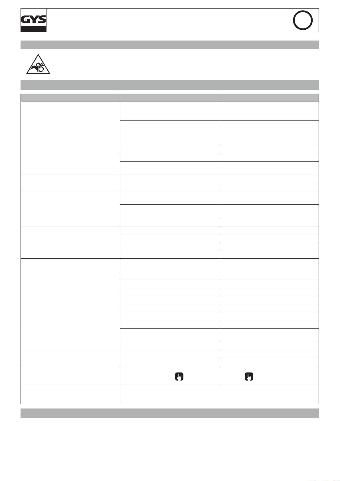
MAGYS 400-4 / 400 GR / 500 GR / 500 WS
RISK OF INJURY DUE TO MOVING PARTS
The wire feeders contain moving parts that may catch hands, hair, clothes or tools and lead to injuries!
• Do not touch rotating / moving / feeding parts of the machine!
• Make sure that all panels remain closed when in use!
• Do not wear gloves when setting up the wire and changing the wire reel.
TROUBLESHOOTING
SYMPTOMS POSSIBLE CAUSES REMEDIES
Debris is blocking up the opening.
The welding wire speed is not constant.
The wire-feeder motor doesn’t operate.
Bad wire feed.
No welding current
The wire jams (after the rollers)
The welding bead is porous
The arc produces a lot of sparks
No gas ow at the end of the torch. Bad gas connection.
When powering on:
The display (9) shows « Err » and the display
(10) shows « 002 ».
When powering on:
The display (9) shows « Err » and the display
(10) shows « 001 ».
The wire skids in the rollers.
The rollers slide over the wire Check and tighten the roller’s screws.
Reel or roller brake too tight. Adjust the brake and rollers.
Electrical supply problem.
Covering wire guide dirty or damaged. Clean or replace
Reel brake too tight Adjust the brake
Bad connection to the main supply.
Bad earth connection.
Torch trigger inoperative. Check the torch trigger / replace torch
Guide wire sheath crushed. Check the sheath and torch body.
Wire jammed in the torch Clean or replace.
No capillary tube. Check the presence of capillary tube.
Wire speed too fast Reduce the wire speed
The gas ow rate is not sufcient.
Gas bottle empty. Replace
Gas quality unsatisfactory. Replace
Air ow or wind inuence. Prevent drafts, protect welding area.
Gas nozzle dirty. Clean or replace the gas nozzle.
Poor quality wire. Use suitable WIRE for MIG-MAG welding.
Work-piece in bad condition. (rust, etc…) Clean the metal before welding.
Arc voltage too low or too high. See welding settings.
Bad earth connection.
Insufcient gas ow. Adjus the gas ow.
At least one of the 3 keys
The Torch’s trigger is pressed. The trigger must be released.
is pressed.
EN
Clean out the contact tip or change it and
replace the anti-adherence product.
Ref. 041806
• Check the roller pressure or replace it.
• Wire diameter incompatible with roller
• Covering wire guide in the torch incompatible.
Check that the power switch is in the "On"
position.
Check the mains connection and ensure the
supply is 400 V (3PH).
Check the earth cable (connection and clamp
condition).
Adjust ow range 15 to 25 L / min.
Clean the work-piece.
Check the earth cable (connection and clamp
condition)
Check that the gas pipe is plugged properly.
Check the solenoid valve.
The 3 keys
must be released.
WARRANTY
The warranty covers faulty workmanship for 2 years from the date of purchase (parts and labour).
The warranty does not cover:
• Transit damage.
• Normal wear of parts (eg. : cables, clamps, etc..).
• Damages due to misuse (power supply error, dropping of equipment, disassembling).
• Environment related failures (pollution, rust, dust).
In case of failure, return the unit to your distributor together with:
- The proof of purchase (receipt etc ...)
20
- A description of the fault reported

MAGYS 400-4 / 400 GR / 500 GR / 500 WS
DE
SICHERHEITSANWEISUNGEN
ALLGEMEIN
Die Missachtung dieser Anweisungen und Hinweise kann zu schweren Personen- und Sachschäden
führen. Nehmen Sie keine Wartungarbeiten oder Veränderungen am Gerät vor, die nicht explizit in der
Anleitung gennant werden.
Der Hersteller haftet nicht für Verletzungen oder Schäden, die durch unsachgemäße Handhabung dieses Gerätes enstanden sind.
Bei Problemen oder Fragen zum korrekten Gebrauch dieses Gerätes, wenden Sie sich bitte an entsprechend qualiziertes und geschultes Fachpersonal.
UMGEBUNG
Dieses Gerät darf ausschließlich für Schweißarbeiten für die auf dem Siebdruck-Aufdruck bzw. dieser Anleitung angegebenen Materialanforderungen
(Material, Materialstärke, usw) verwendet werden. Es wurde allein für die sachgemäße Anwendung in Übereinstimmung mit konventionellen
Handelspraktiken und Sicherheitsvorschriften konzipiert. Der Hersteller ist nicht für Schäden bei fehlerhaften oder gefährlichen Verwendung nicht
verantwortlich.
Verwenden Sie das Gerät nicht in Räumen, in denen sich in der Luft metallische Staubpartikel benden, die Elektrizität leiten können. Achten Sie
sowohl beim Betrieb als auch bei der Lagerung des Gerätes auf eine Umgebung, die frei von Säuren, Gasen und anderen ätzenden Substanzen ist.
Achten Sie auf eine gute Belüftung und ausreichenden Schutz bzw. Ausstattung der Räumlichkeiten.
Betriebstemperatur:
zwischen -10 und +40°C (+14 und +104°F).
Lagertemperatur zwischen -20 und +55°C (-4 und 131°F).
Luftfeuchtigkeit:
Niedriger oder gleich 50% bis 40°C (104°F).
Niedriger oder gleich 90% bis 20°C (68°F).
Das Gerät ist bis in einer Höhe von 1.000m (über NN) einsetzbar.
SICHERHEITSHINWEISE
Lichtbogenschweißen kann gefährlich sein und zu schweren - unter Umständen auch tödlichen - Verletzungen führen.
Beim Lichtbogen ist der Anwender einer Vielzahl potentieller Risiken ausgesetzt: gefährliche Hitzequelle, Lichtbogenstrahlung, elektromagnetische
Störungen (Personen mit Herzschnittmacher oder Hörgerät sollten sich vor Arbeiten in der Nähe der Maschinen von einem Arzt beraten lassen),
elektrische Schläge, Schweißlärm und -rauch.
Schützen Sie daher sich selbst und andere. Beachten Sie unbedingt die folgenden Sicherheitshinweise:
Die Strahlung des Lichtbogens kann zu schweren Augenschäden und Hautverbrennungen führen. Die Haut muss durch geeignete,
trockene Schutzbekleidung (Schweißerhandschuhe, Lederschürze, Sicherheitsschuhe) geschützt werden.
Tragen Sie bitte elektrisch- und wärmeisolierende Schutzhandschuhe.
Tragen Sie bitte Schweißschutzkleidung und einen Schweißschutzhelm mit einer ausreichenden Schutzstufe (je nach Schweißart und
-strom). Schützen Sie Ihre Augen bei Reinigungsarbeiten. Kontaktlinsen sind ausdrücklich verboten!
Schirmen Sie den Schweißbereich bei enstprechenden Umgebungsbedingungen durch Schweißvorhänge ab, um Dritte vor
Lichtbogenstrahlung, Schweißspritzern, usw. zu schützen.
In der Nähe des Lichtbogens bendliche Personen müssen ebenfalls auf Gefahren hingewiesen werden und mit den nötigen Schutz
ausgerüstet werden.
Bei Gebrauch des Schweißgerätes ensteht sehr großer Lärm, der auf Dauer das Gehör schädigt. Tragen Sie daher im Dauereinsatz
ausreichend Gehörschutz und schützen Sie in der Nähe arbeitende Personen.
Achten Sie auf einen ausreichenden Abstand mit ungeschützten Hände, Haaren und Kleidungstücken zum Lüfter.
Entfernen Sie unter keinen Umständen das Gerätegehäuse, wenn dieses am Stromnetz angeschlossen ist. Der Hersteller haftet nicht
für Verletzungen oder Schäden, die durch unsachgemäße Handhabung dieses Gerätes bzw. Nichteinhaltung der Sicherheitshinweise
entstanden sind.
ACHTUNG! Das Werkstück ist nach dem Schweißen sehr heiß! Seien Sie daher im Umgang mit dem Werkstück vorsichtig, um
Verbrennungen zu vermeiden. Achten Sie vor Instandhaltung / Reinigung eines wassergekühlten Brenners darauf, dass Kühlaggregat
nach Schweißende ca. 10min weiterlaufen zu lassen, damit die Kühlüssigkeit entsprechend abkühlt und Verbrennungen vermieden
werden.
Der Arbeitsbereich muss zum Schutz von Personen und Geräten vor dem Verlassen gesichert werden.
SCHWEISSRAUCH/-GAS
Beim Schweißen entstehen Rauchgase bzw. toxische Dämpfe, die zu Sauerstoffmangel in der Atemluft führen können. Sorgen Sie
daher immer für ausreichend Frischluft, technische Belüftung (oder ein zugelassenes Atmungsgerät).
Verwenden Sie die Schweßanlagen nur in gut belüfteten Hallen, im Freien oder in geschlossenen Räumen mit einer den aktuellen
Sicherheitsstandards entsprechender Absaugung.
21
MAGYS 400-4 / 400 GR / 500 GR / 500 WS
Achtung! Bei Schweißarbeiten in kleinen Räumen müssen Sicherheitsabstände besonders beachtet werden. Beim Schweißen von Blei, auch in Form
von Überzügen, verzinkten Teilen, Kadmium, «kadmierte Schrauben», Beryllium (meist als Legierungsbestandteil, z.B. Beryllium-Kupfer) und andere
Metalle entstehen giftige Dämpfe. Erhöhte Vorsicht gilt beim Schweißen von Behältern. Entleeren und reinigen Sie diese zuvor. Um die Bildung von
Giftgasen zu vermeiden bzw. zu verhindern, muss der Schweißbereich des Werkstückes von Lösungs- und Entfettungsmitteln gereinigt werden.
Die zum Schweißen benötigten Gasaschen müssen in gut belüfteter, gesicherter Umgebung aufbewahrt werden. Lagern Sie sie ausschließlich in
vertikaler Position und sichern Sie sie z.B. mithilfe eines entsprechenden Gasaschenfahrwagens gegen Umkippen. Informationen zum richtigen
Umgang mit Gasaschen erhalten Sie von Ihrem Gaselieferanten.
Schweißarbeiten in unmittelbarer Nähe von Fett und Farben sind grundsätzlich verboten!
DE
BRAND- UND EXPLOSIONSGEFAHR
Sorgen Sie für ausreichenden Schutz des Schweißbereiches. Der Sicherheitsabstand für Gasaschen (brennbare Gase) und
andere brennbare Materialien beträgt mindestens 11 Meter.
Brandschutzausrüstung muss am Schweißbplatz vorhanden sein.
Beachten Sie die beim Schweißen entstehende heiße Schlacke, Spritzer und Funken. Sie sind eine potentielle Entstehungsquelle
für Feuer oder Explosionen.
Behalten Sie einen Sicherheitsabstand zu Personen, entammbaren Gegenständen und Druckbehältern.
Schweißen Sie keine Behälter, die brennbare Materialien enthalten (auch keine Reste davon) -> Gefahr entammbarer Gase). Bei geöffneten Behältern
müssen vorhandene Reste entammbarer oder explosiver Stoffe entfernt werden.
Arbeiten Sie bei Schleifarbeiten immer in entgegengesetzer Richtung zu diesem Gerät und entammbaren Materialen.
GASDRUCKAUSRÜSTUNG
Austretendes Gas kann in hoher Konzentration zum Erstickungstod führen. Sorgen Sie daher immer für eine gut belüftete Arbeitsund Lagerumgebung.
Achten Sie darauf, dass die Gasaschen beim Transport verschlossen sind und das Schweißgerät ausgeschaltet ist. Lagern Sie die
Gasaschen ausschließlich in vertikaler Position und sichern Sie sie z.B. mithilfe eines entsprechenden Gasaschenfahrwagens
gegen Umkippen.
Verschließen Sie die Flaschen nach jedem Schweißvorgang. Schützen Sie sie vor direkter Sonneneinstrahlung, offenem Feuer und starken
Temperaturschwankungen (z.B. sehr tiefen Temperaturen).
Positionieren Sie die Gasaschen stets mit ausreichendem Abstand zu Schweiß- und Schleifarbeiten bzw. jeder Hitze-, Funken- und Flammenquelle.
Halten Sie mit den Gasaschen Abstand zu Hochspannung und Schweißarbeiten. Das Schweißen einer Druckglasasche ist untersagt.
Bei Erstöffnung des Gasventils muss der Plastikverschluss/Garantiesiegel von der Flasche entfernt werden. Verwenden Sie ausschließlich Gas, das für
die Schweißarbeit mit den von Ihnen ausgewählten Materialen geeignet ist.
ELEKTRISCHE SICHERHEIT
Das Schweißgerät darf ausschließlich an einer geerdeten Netzversorgung betrieben werden. Verwenden Sie nur die empfohlenen
Sicherungen.
Das Berühren stromführender Teile kann tödliche elektrische Schläge, schwere Verbrennungen bis zum Tod verursachen.
Berühren Sie daher UNTER KEINEN UMSTÄNDEN Teile des Geräteinneren oder das geöffnete Gehäuse, wenn das Gerät im Betrieb ist..
Trennen Sie das Gerät IMMER vom Stromnetz und warten Sie zwei weitere Minuten BEVOR Sie das Gerät öffnen, damit sich die Spannung der
Kondensatoren entladen kann.
Berühren Sie niemals gleichzeitig Brenner und Masseklemme!
Der Austausch von beschädigten Kabeln oder Brennern darf nur von qualiziertem und geschultem Fachpersonal vorgenommen werden. Tragen Sie
beim Schweißen immer trockene, unbeschädigte Kleidung. Tragen Sie unabhängig von den Umgebungsbedingungen immer isolierendes Schuhwerk.
CEM-KLASSE DES GERÄTES
ACHTUNG! Dieses Gerät wird als Klasse A Gerät eingestuft. Es ist nicht für den Einsatz in Wohngebieten bestimmt, in denen
die lokale Energieversorgung über das öffentliche Niederspannungsnetz geregelt wird. In diesem Umfeld ist es auf Grund von
Hochfrequenz-Störungen und Strahlungen schwierig die elektromagnetische Verträglichkeit zu gewährleisten.
Das Gerät entspricht der Norm CEI 61000-3-12 sofern die Stärke des Kurzschlusses Ssc größer oder gleich 3.9 MVA an
der Schnittstelle zwischen der Stromversorgung des Benutzers und der öffentlichen Versorgung ist. Der Installateur und der
Betreiber sind dafür verantwortlich, dass das Gerät nur an einer Stromversorgung mit einer Kurzschlussstärke Ssc höher oder
gleich 3.9 MVA angeschlossen ist, indem sie sich wenn nötig beim Versorgungsnetzbetreiber informieren.
Ce matériel est conforme à la CEI 61000-3-11.
ELEKTROMAGNETISCHE FELDER UND STÖRUNGEN
Der durch Leiter ießende elektrische Strom erzeugt lokale elektrische und magnetische Felder (EMF). Beim Betrieb von
Lichtbogenschweißanlagen kann es zu elektromagnetischen Störungen kommen.
Durch den Betrieb dieses Gerätes können elektromedizinische, informationstechnische und andere Geräte in ihrer Funktionsweise beeinträchtigt
werden. Personen, die Herzschrittmacher oder Hörgeräte tragen, sollten sich vor Arbeiten in der Nähe der Maschine, von einem Arzt beraten lassen.
Zum Beispiel Zugangseinschränkungen für Passanten oder individuelle Risikobewertung für Schweißer.
22
MAGYS 400-4 / 400 GR / 500 GR / 500 WS
Alle Schweißer sollten gemäß dem folgenden Verfahren die Exposition zu elektromagnetischen Feldern aus Lichtbogenschweißgeräten minimieren :
• Elektrodenhalter und Massekabel bündeln, wenn möglich machen Sie sie mit Klebeband fest;
• Achten Sie darauf, dass ihren Oberkörper und Kopf sich so weit wie möglich von der Schweißarbeit entfernt benden;
• Achten Sie darauf, dass sich die Kabel, der Brenner oder die Masseklemme nicht um Ihren Körper wickeln;
• Stehen Sie niemals zwischen Masse- und Brennerkabel. Die Kabel sollten stets auf einer Seite liegen;
• Verbinden Sie die Massezange mit dem Werkstück möglichst nahe der Schweißzone;
• Arbeiten Sie nicht unmittelbar neben der Schweißstromquelle;
• Während des Transportes der Stromquelle oder des Drahtvorschubkoffer nicht schweißen.
Personen, die Herzschrittmacher oder Hörgeräte tragen, sollten sich vor Arbeiten in der Nähe der Maschine, von einem Arzt
beraten lassen.
Durch den Betrieb dieses Gerätes können elektromedizinische, informationstechnische und andere Geräte in Ihrer Funktionsweise
beeinträchtigt werden.
DE
HINWEIS ZUR PRÜFUNG DES SCHWEISSPLATZES UND DER SCHWEISSANLAGE
Allgemein
Der Anwender ist für den korrekten Gebrauch des Schweißgerätes und des Zubehörs gemäß der Herstellerangaben verantwortlich. Die Beseitigung
bzw. Minimierung auftretender elektromagnetischer Störungen liegt in der Verantwortung des Anwenders, ggf. mit Hilfe des Herstellers. Die korrekte
Erdung des Schweißplatzes inklusive aller Geräte hilft in vielen Fällen. In einigen Fällen kann eine elektromagnetische Abschirmung des Schweißstroms
erforderlich sein. Eine Reduzierung der elektromagntische Störungen auf ein niedriges Niveau ist auf jeden Fall erforderlich.
Prüfung des Schweißplatzes
Das Umfeld sollte vor der Einrichtung der Lichtbogenschweißeinrichtung auf potenzielle elektromagnetische Probleme geprüfen werden. Zur Bewertung
potentieller elektromagnetischer Probleme in der Umgebung muss folgendes berücksichtigt werden:
a) Netz-, Steuer-, Signal-, und Telekommunikationsleitungen;
b) Radio- und Fernsehgeräte;
c) Computer und andere Steuereinrichtungen;
d) Sicherheitseinrichtungen, zum Beispiel, Industriematerialschutz;
e) die Gesundheit benachbarter Personen, insbesondere wenn diese Herzschrittmacher oder Hörgeräte tragen;
f) Kalibrier- und Messeinrichtungen;
g) die Störfestigkeit anderer Einrichtungen in der Umgebung.
Der Anwender muss prüfen, ob andere Werkstoffe in der Umgebung benutzt werden können. Weitere Schutzmaßnahmen können dadurch erforderlich
sein;
h) die Tageszeit, zu der die Schweißarbeiten ausgeführt werden müssen.
Die Größe der zu beachtenden Umgebung ist von der Struktur des Gebäudes und der anderen dort stattndenden Aktivitäten abhängig. Die Umgebung
kann sich auch außerhalb der Grenzen der Schweißanlagen erstrecken.
Prüfung des Schweißgerätes
Neben der Überprüfung des Schweißplatzes kann eine Überprüfung des Schweißgerätes weitere Probleme lösen. Die Prüfung sollte gemäß Art. 10 der
IEC/CISPR 11:2009 durchgeführt werden. In-situ Messungen können auch die Wirksamkeit der Minderungsmaßnahmen bestätigen.
HINWEIS ÜBER DIE METHODEN ZUR REDUZIERUNG ELEKTROMAGNETISCHER FELDER
a. Öffentliche Stromversorgung: Es wird empfohlen das Lichtbogenschweißgerät gemäß der Hinweise des Herstellers an die öffentliche Versorgung
anzuschließen. Falls Interferenzen auftreten, können weitere Maßnahmen erforderlich sein (z.B. Netzlter). Eine Abschirmung der Versorgungskabel
durch ein Metallrohr kann erforderlich sein. Kabeltrommeln sollten vollständig abgerollt werden. Abschirmung von anderen Einrichtungen in der
Umgebung oder der gesamten Schweißeinrichtung können erforderlich sein.
b. Wartung des Gerätes und des Zubehörs: Es wird empfohlen das Lichtbogenschweißgerät gemäß der Hinweise des Herstellers an die öffentliche
Versorgung anzuschließen. Alle Zugänge, Betriebstüren und Deckel müssen geschlossen und korrekt verriegelt sein, wenn das Gerät in Betrieb ist.
Das Schweißgerät und das Zubehör sollten in keiner Weise geändert werden mit Ausnahme der in den Anweisungen des Geräteherstellers erwähnten
Änderungen und Einstellungen. Für die Einstellung und Wartung der Lichtbogenzünd- und stabilisierungseinrichtungen müssen die Anweisungen des
Geräteherstellers besonders zu beachten.
c. Schweißkabel: Schweißkabel sollten so kurz wie möglich und eng zusammen am Boden verlaufen.
d. Potenzialausgleich: Alle metallischen Teile des Schweißplatzes sollten des Schweißplatzes sollten in den Potentialausgleich einbezogen werden.
Es besteht trotzdem die Gefahr eines elektrischen Schlages, wenn Elektrode und Metallteile gleichzeitig berührt werden. Der Anwender muss sich
von metallischen Bestückungen isolieren.
e. Erdung des Werkstücks: Die Erdung des Werkstücks kann in bestimmte Fällen die Störung reduzieren. Die Erdung von Werkstücken, die
Verletzungsrisiken für Anwender oder Beschädigung anderer elektrischen Materialen erhöhen können, sollte vermieden werden. Die Erdung kann
direkt oder über einen Kondensator erfolgen. Der Kondensator muss gemäß der nationalen Normen gewählt werden.
f. Schutz und Trennung: Eine Abschirmung von anderen Einrichtungen in der Umgebung oder der gesamten Schweißeinrichtung kann die Störungen
reduzieren. Die Abschirmung der ganen Schweißzone kann für Spezialanwendungen in Betracht gezogen werden.
TRANSPORT UND TRANSIT DER SCHWEISSSTROMQUELLE
Ziehen Sie niemals an Brenner oder Kabeln, um das Gerät zu bewegen. Das Gerät darf ausschließlich in vertikaler Position
transportiert werden.
Das Gerät darf nicht über Personen oder Objekte hinweg gehoben werden.
Halten Sie sich unbedingt an die unterschiedlichen Transportrichtlinien für Schweißgeräte und Gasaschen. Diese haben verschiedene
Beförderungsnormen.
Die Drahtspule sollte vor dem Heben und Transport des Schweißgerätes entfernt werden.
Unterschätzen Sie nicht das Eigengewicht des Gerätes! Da das Gerät über keine weitere Transporteinrichtung verfügt, liegt es Ihrer eigenen
Verantwortung dafür Sorge zu tragen, dass Transport und Bewegung des Gerätes sicher verlaufen (Achten Sie darauf das Gerät nicht zu kippen).
Schweißkriechströme können Erdungsleiter zerstören, die Schweißanlage und elektrische Geräte beschädigen und die Erwärmung der Bauteile
verursachen, die zum Brand führen können.
23
 Loading...