

Page 1
FR - 2 / 3-8 / 45-50
EN - 2 / 9-14 / 45-50
DE - 2 / 15-20 / 45-50
ES - 2 / 21-26 / 45-50
RU - 2 / 27-32 / 45-50
NL - 2 / 33-38 / 45-50
IT - 2 / 39-44 / 45-50
FLEX 250 CEL
73502-V7-25/10/2016
Page 2
2
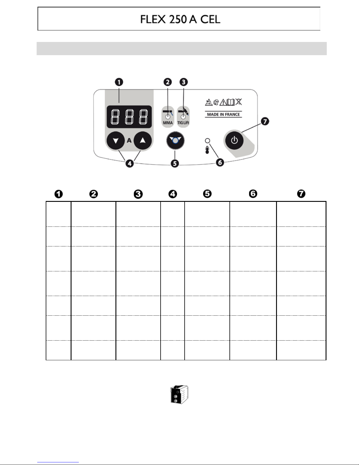
FACE AVANT/FRONTAL SIDE/FRONTSEITE UND ANSCHLÜSSE/CARA DELANTERA/ПЕРЕДНЯЯ ПАНЕЛЬ /
VOORZIJDE
FR
Afficheur Voyant mode
« soudage à
l’électrode » (MMA)
Voyant mode
« soudage à
l’électrode réfrac
taire»
(TIG)
Sélecteur
valeur +
ou -
Bouton sélection/
validation
Voyant de protection
thermique
Bouton de mise e n
marche / veille
EN
Display Mode indicator
« electrode welding »
(MMA)
Mode indicator « non
consumable electrode
welding» (TIG)
Select
button «
+
or – »
Selection / v alidation
button
Thermal protection
indicator
On/stand by button
DE
Anzeige
Schweißmodusanzeige
MMA
Schweißmodusanzeige
«WIG
Kontaktzündung»
(TIG)
Wahl
Drucktaster
+ oder -
Button-Auswahl /
Validierung
Gelbe
Übertemperaturanzeige
EIN/ AUS- Taste
ES
Indicador Indicador modo
« soldadura con
electrodo recubierto»
(MMA)
Indicador modo
« soldadura con
electrodo refractario»
(TIG)
Selector
valor + o -
Botón selección /
validación
Indicador luminoso
amarillo de protección
térmica
Puesta en marcha /
stand by
RU
Индикатор Лампочка режима
MMA
Лампочка режима
TIG
Клавиши
выбора +
или –
Клавиша выбора/
подтверждения
Желтый индикатор
температурной
защиты
Кнопка включение /
вахтенный режим
NL
Display Lampje voor
« booglassen met
beklede elektrode »
(MMA)
Lampje voor
« booglassen met
niet-afsmeltende
elektrode » (TIG)
Selectie
waarde +
of -
Knop selectie/
bevestiging
Lampje voor
thermische beveiliging
Aan/uit knop
IT
Schermo Spia modo "saldatura
all'elettrodo" (MMA)
Spia modo "saldatura
all'elettrodo
refrattari o " (TIG)
Selettore
valore + o
-
Tasto
selezione/conferma
Spia di protezione
termica
Tasto di avviamento /
standby
FLEX 250 CEL
17kg
Page 3
3
DESCRIPTION
Merci de votre choix ! Afin de tirer le maximum de satisfaction de votre poste, veuillez lire avec attenti on ce qui suit :
Ces postes de soudure Inverter, portables, ventilés, sont conçus pour le soudage à l’électrode enrobée (MMA) et à
électrode réfractaire (TIG Lift) en courant continu (DC). En MMA, ils soudent tout type d’électrode : rutile, inox,
fonte, basique et cellulosique. En Tig, ils soudent la plu part des métaux sauf l’alum inum et ses alliages. Ils sont
protégés pour le fonctionnemen t sur groupes électrogènes.
ALIMENTATION-MISE EN MARCHE
• Le FLEX 250 A CEL équipé d’un système « Flexible Voltage » s’alimente sur une ins tall at io n é lec triq ue AVEC terre
comprise entre 110V et 480V monophasée ou triphasée (50 - 60 Hz). Le courant effectif absorbé (I1eff) est
indiqué sur l'appareil pour les conditions d'utilisation maximales. Vérifier que l'alimentation et ses protections
(fusible et/ ou disjoncteur) sont com patibles avec le c ourant nécessaire en utilisation. Ce poste est livré sans prise.
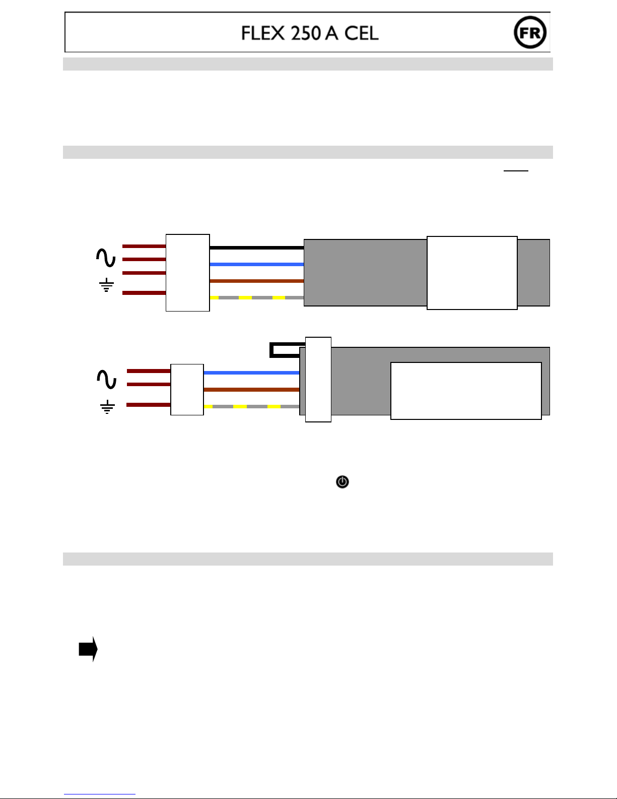
Schéma de connexion
3
+
Connection à une prise triphasée
2
+
Connection à une prise monophasée
*ATTENTION ! Dans le cas d’une connection à une prise monophasé, le fil inutilisé doit être isolé afin
qu’il n’entre jamais en contact avec les autres fils.
• La mise en marche s’effectue par une pression sur la touche ( )
• Ces appareils sont de Classe A. Ils sont conçus pour un emploi dans un environnement industriel ou
professionnel. Dans un environnement différent, il peut être difficile d’assurer la compatibilité électromagnétique,
à cause de perturbations conduites aussi bien que rayonnées.
• Ne pas utiliser dans un environnement comportant des poussières métalliques conductrices.
SOUDAGE A L' ÉLECTRODE ENROBEE (M OD E M MA)
• Brancher les câbles porte électrode et pince de masse dans les connecteurs. Respecter les polarités indiquées sur
l'emballage des électrodes.
• Respecter les règles classiques du soudage.
• Votre apparei l est muni de 3 fonctionnalités spécifiques aux Inverters :
Le H
OT START (mode réglable, cf ci-dessous) procure une surintensité en début de soudage.
L’A
RC FORCE (mode réglable, cf ci-dessous) délivre une surintensité qui évite le collage lorsque l’électrode
rentre dans le bain.
L'A
NTI-STICKING vous permet de décoller facilement votre électrode sans la faire roug ir en cas de collage.
Activation du mode MMA et réglage de l’intensité :
- Sélectionner la position MMA avec le sélecteur (presser 3 secondes)
- Régler l’int ensité souhaitée (afficheur ) grâce aux touches.
1- phase 1
2- phase 2
3- phase 3
4- terre
1- phase 1
2- phase 2 ou neutre
3- Terre
*
Page 4
4
Hot Start et Arc Force réglables :
FLEX 250 A CEL
Hot Start 0 90%
Arc Force 0 90% ou type d’électrode
L’arc force est réglable de 0 à 90% puis passe sur des modes d’électrodes, « rut », « bas » et « cel ». Ces derniers
modes sont des réglages optimaux pour les différents types d’électrodes.
Conseils :
Hot Start faible pour les tôles fines.
Hot Start élev é pour les métaux difficiles à souder (pièces sa les ou oxydées).
Pour régler le Hot Start et Arc Force, suivre les étapes page suivante.
Presser le sélecteur
Régler le pourcentage d’Hot Start souhaité (afficheur ) grâce aux touches
Valider la valeur souhaitée en pressant sur le sélecteur
Régler le pourcentage d’Arc Force ou le type d’électrodes souhaité (afficheur ) grâce aux
touches .
Valider la valeur souhaitée en pressant sur le sélecteur
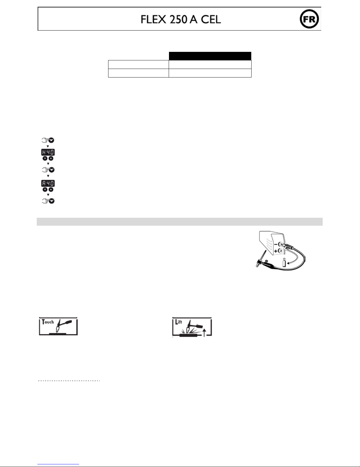
SOUDAGE TIG LIFT (MODE TIG)
Le soudage TIG DC req uie r t une pr o te ctio n g aze us e (A rgo n) .
Pour souder en TIG, suivre les étapes suivantes :
1. Connecter la pince de masse sur la polarité positive (+).
2. Brancher une torche « à valve » sur la polarité négative (-).
3. Raccorder le tuyau de gaz au manodétendeur de la bouteille de gaz.
Il sera parf ois nécessaire de le couper avant l’écrou si ce dernier n’est pas adapté au manodétendeur
4. Sélectionner la position TIG avec le sélecteur . (presser 3 secondes)
5. Régler l’intensité souhaitée (afficheur ) grâce aux touches , selon l’épaisseur à souder (30A/mm).
6. Régler le débit de gaz sur le manodétendeur de la bouteille de gaz, puis ouvrir la valve de la torche
7. Pour amorcer :
a- toucher l’électrode sur la
pièce à souder
b- relever l’électrode 2 à 5 mm
de la pièce à souder
8. En fin de soudure : Lever 2 fois l'arc (haut-bas-haut-bas) pour déclencher l'évanouissement automatique (cf
paragrap he ci-dessous). Ce mouvement doit être effectué en moins de 4 secondes, sur une hauteur de 5 à 10
mm. Puis fermer la valve de la torche pour arrêter le gaz après refroidissement de l'électrode.
Évanouissement automatique de l'arc à durée réglable
Activation de la fonction :
Cela correspond en fin de soudure au temps nécessaire pour la baisse progressive du courant de soudage jusqu’à
l’arrêt de l’arc. Cette fonction permet d’éviter les fissures et les cratères de fin de soudure.
Par défaut cette fonction n'est pas activée (OFF). Pour l'activer, procéder comme suit:
Page 5
5
1- Presser sur le sélecteur
2- Régler le temps d'évanouissement souhaité de 1 à 10 sec (afficheur ) grâce aux
touches
3- Valider la valeur souhaitée en pressant sur le sélecteur .
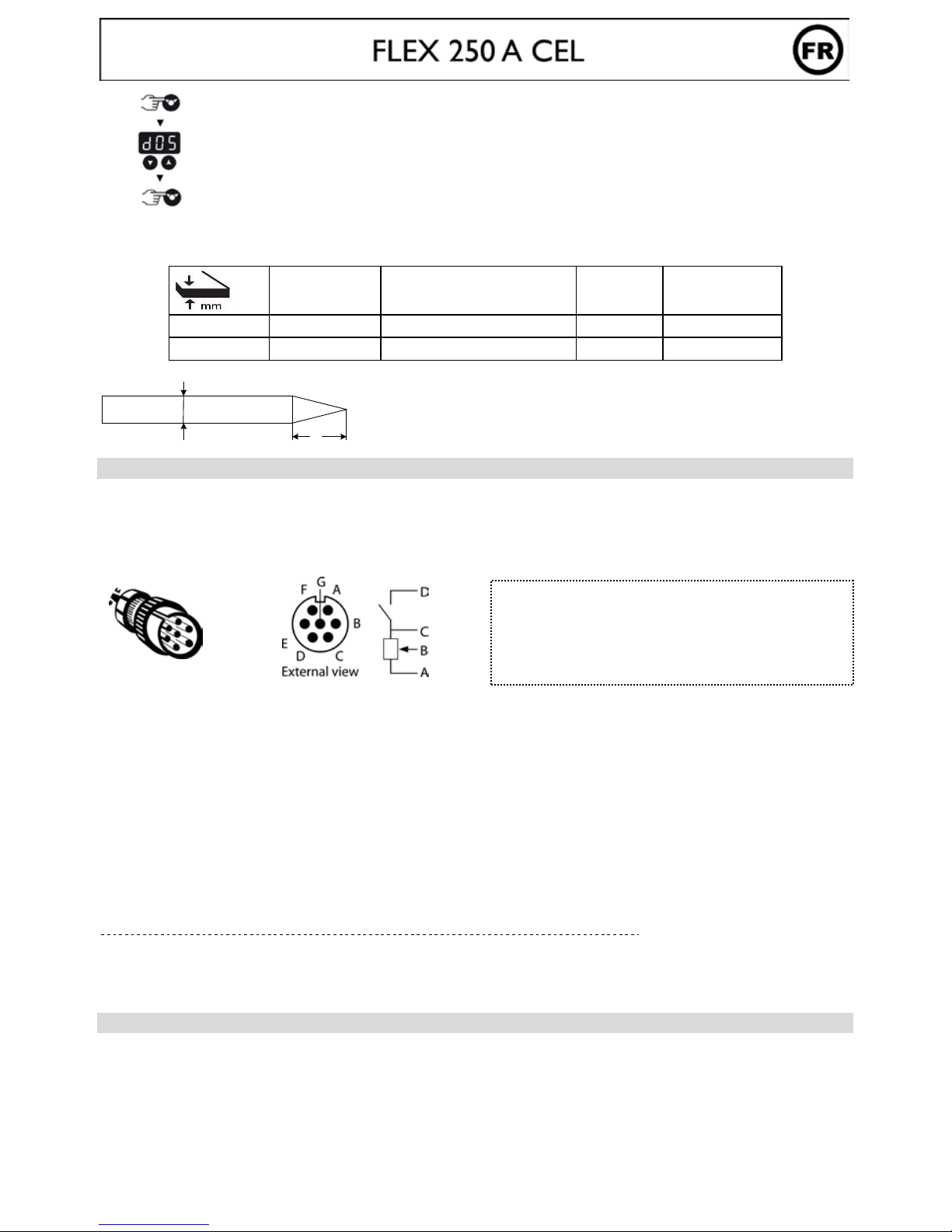
Combinaisons conseillées / affutage électrode
Courant (A)
∅
Electrode (mm)
= ∅ fil (métal d’apport)
∅
Buse
(mm)
Débit
(Argon l/mn)
0,5-5 10-130 1,6 9,8 6-7
4-10 130-250 2,4 11 7-8
Pour un fonctionnement optimal vous devez utiliser une électrode affûtée de la manière s uivante :
d
l
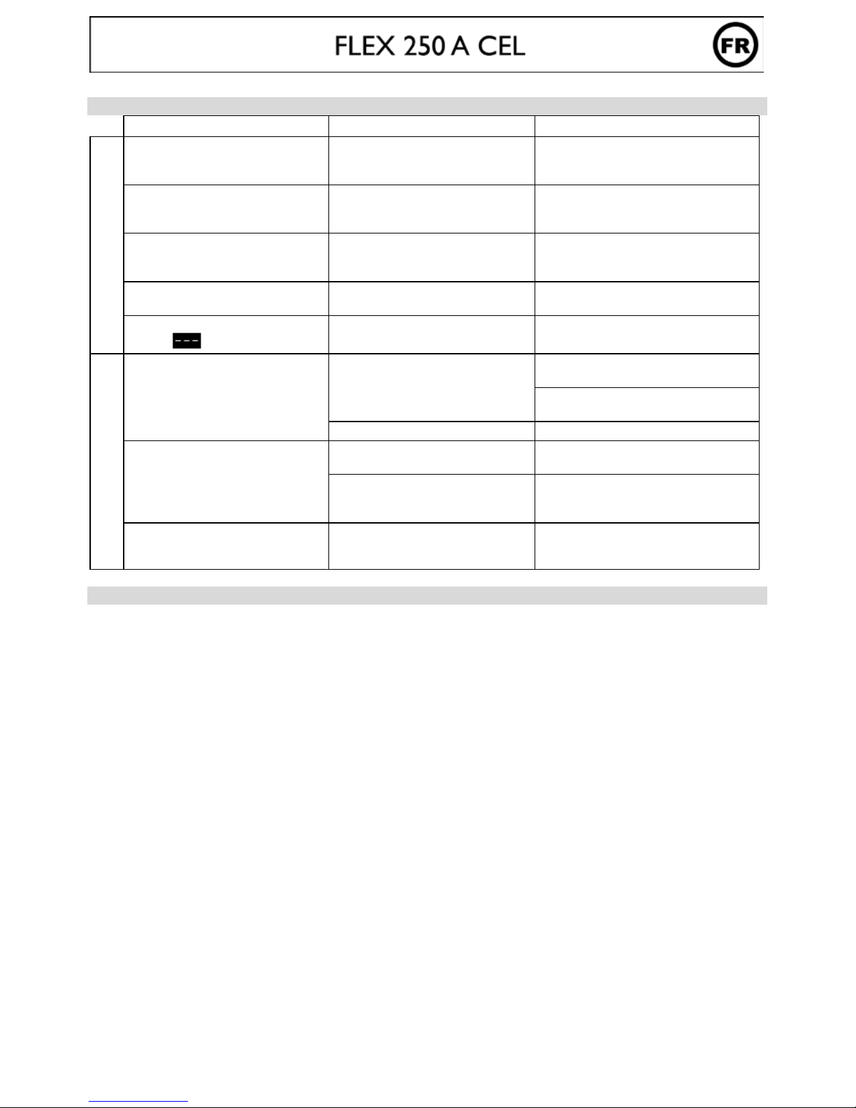
COMMANDE A DISTANCE
La commande à distance fonctionne en mode TIG et en MMA.
Connectique
Le FLEX 250A CEL est équipé d’une prise femelle pour commande à distance. La prise mâle spécifique 7 points
(option ref. 045699) permet d’ y raccorder votre commande à distance manuelle (R C) ou à pédale (PEd).
Pour le câblage suivre le schéma ci-dessous.
Branchement
1- Allumer le poste
2- Brancher la pédale ou la télécommande sur la face avant de l’appareil.
3- L’afficheur clignote en affichant « No » (Rien),
4- Sélectionner votre type de commande à l’aide des touches :
No (Rien) « RC » (Remote Control/commande à distance) PEd (Pédale)
5- Après 2 secondes d’inactivité, l’afficheur se fige sur la valeur puis réaffiche l’intensité de soudage
Nb : En cas d’erreur, débrancher votre commande à distance, le poste vous indique que plus rien
n’est connecté : « No ». Puis rebrancher votre commande et refaites la sélection.
Remarque : Ce choix sera réafiché à chaque mise en route.
Fonctionnement
Commande à Distance.manuelle (opt ion ref. 045675) / Pédale (option ref. 045682)
La commande à distance manuelle permet de faire varier le courant de l’intensité mini (DC : 10A / MMA : 10) à
l’intensité définie par l’utilisateur (afficheur).
Dans cette configuration, tous les modes et fonctionnalités du poste sont acc essibles et paramétrables.
PROTECTION THERMIQUE ET FACTEURS DE MARCHE
• Protection thermique : le voyant s ’allume et la durée de refroidissement est de 1 à 5 mn en fonction de la
température ambiante.
• Laisser l’appareil branché après soudage pour permettre le refroidissement
• Le po ste dé crit a une caractéristique de sortie de type "courant consta nt". So n facteur de marche selon la norme
EN60974-1 est indiqué dans le tableau suivant :
L = 2,5 x d.
L
D : Contact du switch
C : Masse
B : Curseur
A : + 5V
Nb : la valeur du potentiomètre doit être de 10 KΩ
Ref.045699
Page 6

6
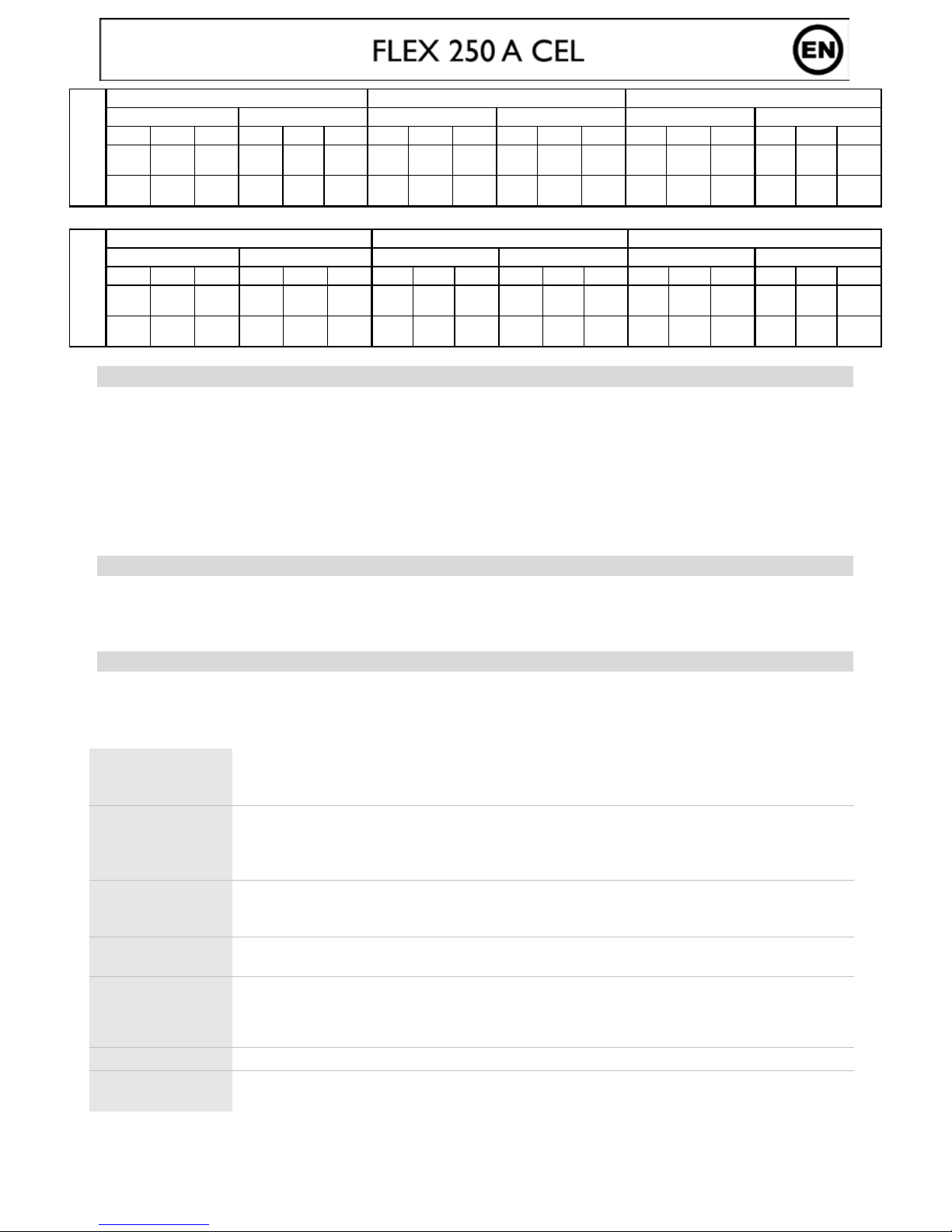
MMA
U1 = 110V U1 = 230V U1 = 400V
1~ 3~ 1~ 3~ 1~ 3~
30% 60% 100% 35% 60% 100% 41% 60% 100% 53% 60% 100% 40% 60% 100% 32% 60% 100%
140A 115A 90A 140A 125A 100A 200A 180A 150A 200A 190A 170A 250A 220A 190A 250A 200A 170A
25,6V 24,5V 23,6V 25,6V 25V 24V 28V 27,2V 26V 28V 27,6V 6,8V 30V 28,8V 27,6V 30V 28V 26,8V
TIG
U1 = 110V U1 = 230V U1 = 400V
1~ 3~ 1~ 3~ 1~ 3~
60% 60% 100% 100% 60% 100% 80% 60% 100% 100% 60% 100% 65% 60% 100% 43% 60% 100%
140A 140A 110A 140A 140A 140A 200A 200A 180A 200A 200A 200A 250A 250A 220A 250A 225A 180A
15,6V 15,6V 14,4V 15,6V 15,6V 15,6V 18V 18V 17,2V 18V 18V 18V 20V 20V 18,8V 20V 19V 17,2V
ENTRETIEN
• L'entretien ne doit être effectu é que par une personne qualifiée.
• Couper l'alime ntation en dé br a nchant la pr i se et atte ndr e l ’ arr êt du ve n tilateur avant de t ravailler s ur l'app are i l.
A l’intéri eur , les tensions et int ensités sont élevées et dangereuses.
• Deux à trois fois par an, enlever le capot et dépoussiérer à la soufflette. En p rofiter pour faire véri fier la tenue
des connexions électriques avec un outil isolé par un personnel qualifié.
• Contrôler régu lièrement l'état du c ordon d'al imentation. S i le câble d'aliment ation est e ndommagé, il doit êtr e
remplacé par le fabricant, son service après vente ou une personne de qualification similaire, afin d'éviter un
danger
CONSEILS
• Respecter les polarités (+/-) et intensités de soudage indiquées sur les boîtes d'électrodes
• Enlever l’électrode du porte-électrode lorsque le poste n'est pas utilisé.
• Laisser les ouïes de l'appareil libres pour l’entrée et la sortie d’air.
SÉCURITÉ
Le sou da ge à l'a rc p eut êtr e da ng er eux e t ca us er d es bl ess ur es gr av es v oir e m o rtel les . Prot ég ez v ou s
et protégez les autres.
Respecter les instructions de sécurité suivantes
:
Rayonnements
de l’arc
Protégez-vous à l’aide d’un masque muni de filtres conformes EN 169 ou EN 379.
Pluie, vapeur
d’eau, humidité
Utilisez votre poste dans une atmosphère propre (degré de pollution ≤ 3), à plat et à plus
d’un mètre de la pièce à souder. Ne pas utiliser sous la pluie ou la neige.
Choc électrique
Veiller à bien respecter les règles d’alimentation des postes citées au préala ble. Ne pas
toucher les pièces sous tension. Vérifier que le réseau d'alimentation est adapté au poste.
Chutes Ne pas faire transiter le poste au-dessus de personnes ou d’objets.
Brûlures
Porter des vêtem ents de travail en tis su ignifugé (coton, bleu ou jeans).
Travailler avec des gants de protection et un tablier ignifugé.
Protéger les autres en installant des paravents ininflammables, ou les prévenir de ne pas
regarder l'arc et garder des distances suffisantes.
Risques de feu
Supprimer tous les produits inflammables de l'espace de trav ail. Ne pas travailler en présence
de gaz inflammable.
Fumées
Ne pas inhaler les gaz et fumées de soudage. Utiliser dans un environnement correctement
ventilé, avec ex traction artifi c ielle si soudage en intérieur.
Précautions
supplémentaires
Toute opération de soudage :
- dans des lieux comportant des risques accrus de choc électriqu e,
- dans des lieux fermés,
- en présence de matériau inflammable ou comportant des risques d'explosion, doit toujours
être soumise à l'approbation préalable d'un "responsable expert", et effec tuée en présence
de personnes formées pour inter venir en cas d'urgence.
Les moyens tech niques de protections décrits dans la Spécification Technique CEI/IEC 62081
doivent être appliqués.
Le soudage en pos ition surélevée est interdit, sauf en cas d'u tilisation de plat es-formes de
sécurité.
Page 7

7
Les porteurs de stimulateurs cardiaques doivent consulter un médecin avant d'utiliser ces appareils.
Nous déconseillons toutefois l’utilisation de ces appareils par ces personnes.
Ne pas utiliser le poste pour dégeler des canalisations.
En soudage TIG, manipuler la bouteille de gaz avec précaution, des risques existent si la bouteille ou
la soupape de la bouteille sont endommagées.
RECOMMANDATION POUR RÉDUIRE LES ÉMISSIONS ÉLECTRO-MAGNÉTIQUES
Généralité
L’utilisateur e st res ponsab le de l’insta llatio n et de l’ut ilisa tion de l’app areil sui vant le s instruc tio ns du fabr icant. Si de s
perturbations électromagnétiques sont détectées, il est de la responsabilité de l’utilisateur de résoudre la situation
suivant les recommandations données dans la notice ou avec l’assistance technique du fabricant.
Evaluation de la zone de soudage
Avant d’insta ller l’appareil, l’utilis ateur devra é valuer les pro blèmes éle ctro-magné tiques potentie ls qui po urraient se
présenter dans la zone où est prévue l’installation, en particulier il devra tenir compte des indications suivantes :
a. Autres câblages, câblages de contrôle, câbles téléphoniques et de communication : au dessus, au
dessous et à côt é de l’appareil. ;
b. récepteurs et transmetteurs radio et télévision ;
c. ordinateurs et autres équipements de contrôle ;
d. équipements critiques pour la sécurité tels que les comma ndes de sécurité des équipements industriels ;
la santé des personnes qui se trouvent à proximité de la machine, par exemple des personnes qui portent un
simulateur cardiaque, un appareil auditif, etc… ;
e. équipements servant à calibrer et mesurer ;
f. l’immunité des autres appareils installés dans le local d’utilisation de l’appareil. L’utilisateur devra
s’assurer que les appareils du local sont compatibles entre eux. Ceci pourra de mander de prendre des
précaution s supplémentaires ;
g. le temps de la journée au cours de laquelle l’appareil devra fonction ner ;
h. la surface de la zone à prendre en considération autour de l’appareil dépendra de la structure des
édifices et des autres activités qui se déroulent sur le lieu. La zone considérée peut s’étendre au-delà des
limites des entreprises.
Recommandation sur les méthodes de réduction des émissions électro-magnétiques
a. Alimentation principale : Le poste de soudage devra être relié au réseau d’alimentation
conformément aux recommandations du fabricant. En cas d’interférences, il peut s’avérer utile de
prendre des précautions supplémentaires en filtrant la tension d’alimentation. Il peut s’avérer utile de
blinder le câble d’alimentation dans les installations fixes du poste de soudage, sous goulottes
métalliques ou dispositifs équivalents. Le blindage devrait être électriquement continu sur toute la
longueur du câble. Il devrait être relié au poste de soudage avec un bon contact électrique entre la
goulotte métallique et le boîtier du poste.
b. Câbles de soudage : Les câbles doivent être les plus courts possibles. Les regrouper et, si possible, les
laisser au sol.
c. Protecti on et blindage : La protection et le blindage sélectif d’autres câbles et matériels dans la zone
environnante peut limiter les pr oblèmes de perturbati on.
d. Mise à la terre de la pièce à souder : La mise à la terre de la pièce à souder peut limiter les
problèmes de perturbation. Elle peut être fait directement ou via un condensateur approprié. Ce choix est
fait en fonction des réglementations nationales.
Page 8
8
ANOMALIES, CAUSES, REMÈDES
Anomalies
Causes
Remèdes
MMA-TIG
L’appareil ne délivre pas d e courant
et le voyant jaune de protection
thermique est allumé .
La protection thermique du poste
s’est enclench ée .
Attendre la fin de la période de
refroidissement, environ 2 min. Le
voyant s’éteint.
L’afficheur est allu mé mai s
l’appareil ne délivre pas de courant.
Le câble de pince de masse ou
porte électrode n’est pas connecté
au poste.
Vérifier les branchements.
Le poste est alimenté, vous
ressentez des picotements en
posant la main sur la carrosser ie .
La mise à la terre est défectueus e.
Contrôler la prise et la terre de vo tre
installation.
Le poste soude mal Erreur de polarité
Vérifier la polarité co nseillée sur la
boîte d'électrode.
Lors de la mise en rou te, l’affic heur
indique
La tension d’alimentation est
supérieure à la limite (440V +1 5% )
Vérifier votre installation électrique ou
votre groupe électrogène
TIG
Arc instable
Défaut prove nant de l'électrode en
tungstène
Utiliser u ne électrode en tungstène de
taille appropriée
Utiliser une électrode en tungstène
correctement préparée
Débit de gaz trop important Réduire le débit de gaz
L'électrod e en tungst ène s'oxyd e et
se ternit en fin de soudage
Zone de soudage.
Protéger la z one de soud age cont re les
courants d'air.
Problème de gaz, ou coupure
prématurée du gaz
Contrôler et s erre r tou s le s rac cord s d e
gaz. Attendre que l'électrode
refroidisse avant de couper le gaz.
L'électrod e fond Erreur de polarité
Vérifier qu e la pin ce de masse es t bi en
reliée au +
CONDITIONS DE GARANTIE FRANCE
• La garan tie c o u vr e to ut défaut ou vic e de fabricat io n p endant 2 ans, à compter de la date d’achat (pièces et main
d’œuvre).
• La garantie ne couvre pas les erreurs de tension, incidents dus à un mauvais usage, chute, démontage ou toute
autre avarie due au transport.
• La garantie ne couvre pas l’usure normale des pièces (Ex. : câbles, pinces, etc.).
En cas de panne, retournez l’appareil à votre distributeur (port dû refusé), en y joignant :
- Le justificatif d’achat daté (facture, tickets de caisse…)
- Une note explicative de la panne.
Après la garantie, notre SAV assure les réparations après acceptation d’un devis.
Page 9

9
DESCRIPTION
Thank you for choosing our product! In order to take the most of your welder, please read the following
instructions carefully:
The FLEX 250 A CEL is a portable inverter welding machine, for e lectrode welding (MMA) and TIG Lift in DC. The
machine wel ds rutiles, basic, stainless steel, c ast iron and celulosic e lectrodes. In TIG, it welds mo st metals exc ept
aluminium and alloys. It is protected for use on generators.
POWER SUPPLY – START UP
• The FLEX 250 A CEL is a Flexible Voltage machine can be plugged into a mains s upply between 110V and 480V in
single or three phase (50 - 60 Hz). The absorb ed effec tive c urren t (I1eff ) is sho wn on the machi ne for m aximum
useage conditions. Check that the power supply and i ts protection (fuse amd/or circuit-breaker) are compatible
with the necessary current required for use.
Connection diagram
3
+
Connection to a 3 phase power supply
2
+
Connection to a single phase power supply
*WARNING ! Connection to a single phase plug, the unused wire must be isolated so that it
never comes into contact with the other wires.
• Turn on the machine by pressing ( )
• This machine is a A-class device. It is designed to be used in an industrial or professional environment. In
a different environment, it can be difficult to ensure electromagnetic compatibility, due to conducted
disturbances as well as radiation.
• The FLEX 250 A CEL features primary regulation, it is recommended to use the cables supplied with the
unit.
ELECTRODE WELDING (MMA MODE)
• Leave the machine connected to the supply after welding in order to let it cool down.
• Thermal protection : when the thermal protection is activated, the cooling time is about 2 to 5 min
depending on external temperature.
• Your machine is equipped with 3 functions :
Hot Start gives an adjustable* overcurrent at the beginning of welding.
Arc Force delivers an overcurrent which avoids sticking when the electrode enters the
welding pool.
Anti-Sticking allows easy removal of the electrode in case of sticking.
Selection of MMA Mode and intensity setting :
- Select the MMA position with the selector.
- Adjust the desired current (display ) using the key .
1- phase 1
2- phase 2
3- phase 3
4- Earth
1- phase 1
2- phase 2 ou neutre
3- Earth
Page 10
10
Hot Start & Arc Force adjustments:
FLEX 250 A CEL
Hot Start 0 90%
Arc Force 0 90%, or type of electrode
Adjust the Arc Force from 0 to 90%, then switch to electrode mode « rut », « bas » or « cel ». These modes
are optimum settings for each different types of electrode.
Advice :
low Hot Start : for thin metal sheets
high Hot Start for metals that are difficult to weld (dirty or oxidized pieces)
To adjust the Hot Start and Arc Force, go through the following steps.
Press button
Set the required Hot Start percentage (display ) using button
Validate the required figure by pressing the button
Set the required Arc Force percentage (display ) using key .
Validate the required figure by pressing the selector button.
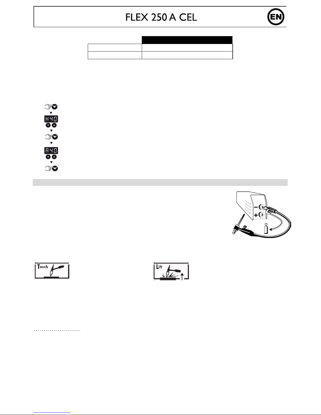
TIG LIFT
DC TIG welding requires protective gas (argon).
Follow the steps below :
1. Connect the earth clamp to the positive socket (+).
2. Connect a torch to the negative socket (-).
3. Connect the gas pipe from the torch to the gas cylinder
4. Select TIG mode using the selection button .
5. Adjust the desired current (display ) using the key .
Advice : Take 30A/mm as a default setting and adjust according to the welding workpiece.
6. Set the gas flow on the flowmeter of the gas cylinder, and then open the valve of the torch
7. To st art :
a- Touch the workpiece with
the electrode
b-
Raise the electrode from
2 to 5 mm from the
workpiece
8. At end of welding :
Raise the torch 2 times in quick succession(raise-lower-raise-lower) to trigger the automatic downslope
(see section below). This movement must be performed in less than 4 sec, at a height of 5 to 10 mm.
Then close the valve of the torch to stop the gas after the electrode has cooled.
Automatic Arc slope with adjustable time
Function activation :
This corresponds to the time required at the end of welding for the gradual decline in the welding current
until the arc stops. This function helps to avoid cracks and craters at end of welding.
Page 11
11
1- Press button for 3 seconds
2. Set the automatic arc slope from 1 to 10 sec (display) using key.
3. Validate the required figue by pressing button .
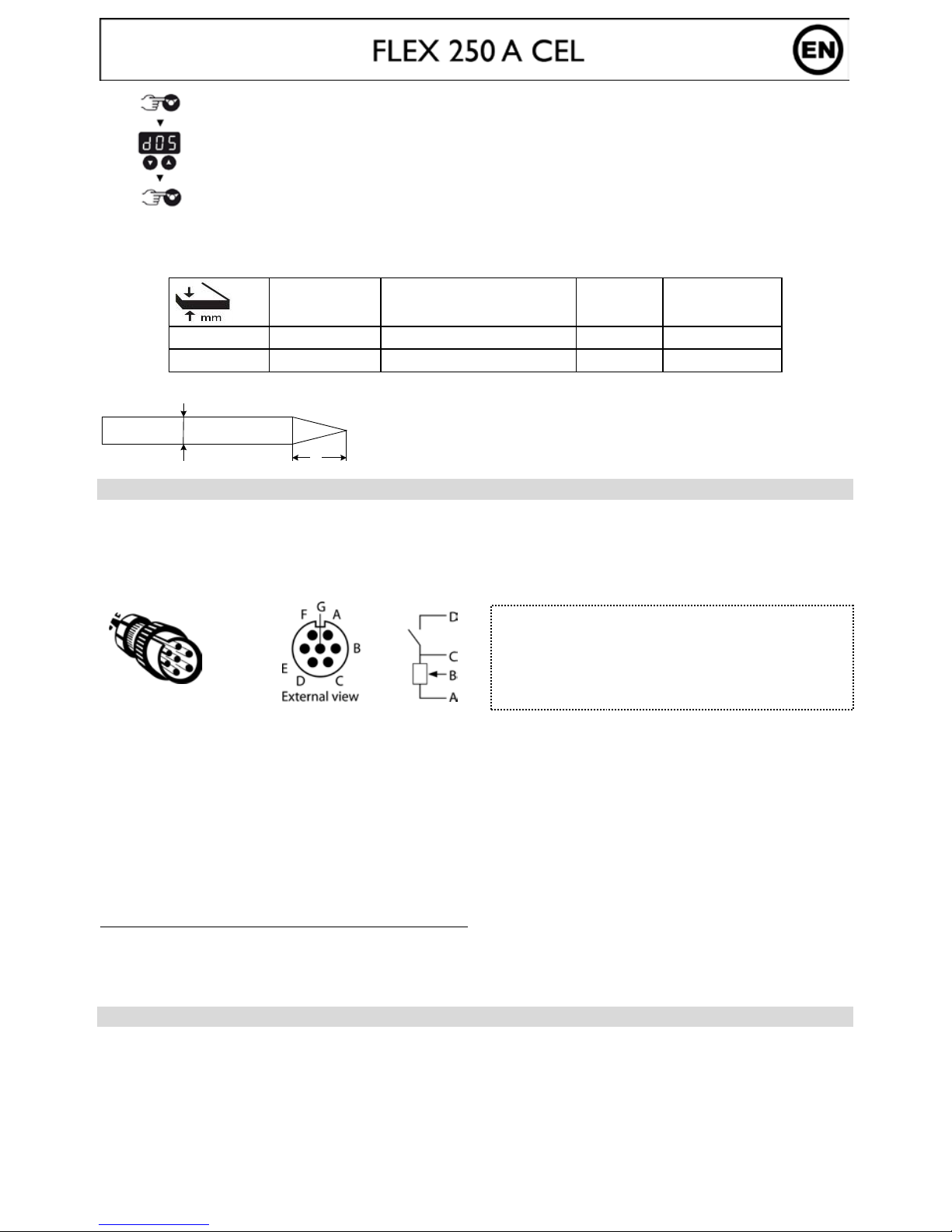
Recommended combinations / Electrode grinding
Current (A)
Ø Electrode (mm)
= Ø wire (filler metal)
Ø Nozzle
(mm)
Flow rate
(Argon L/mn)
0,5-5 10-130 1.6 9.8 6-7
4-8
130-200
2.4
11
7-8
To optimise the weld, use an electrode ground as below :
d
l
REMOTE CONTROL
The remote control operates in TIG and MMA mode.
Connector technology
The FLEX 250A CEL is equipped with a female socket for remote control. The specific 7 poi nt male plug (product
ref.045699) enables connection to a manual remote control (RC) or foot pedal (PEd).
For the cabling layout, see the diagram below.
Connecting
1- Power up the machine
2- Plug the pedal/remote control to the connecting socket on the machine.
3- The screen will flash and display « No » (Nothing),
4- Select the type of control using keys :
« No » (Nothing) / « RC » (Remote Control) / « PEd » (Pedal)
5- After 2 seconds the display will freeze on the chosen selection, then displays the welding current.
NB: In case of error, unplug the remote control, (« No » will be displayed) and re-start the connection process.
Remark: Remote type choice will be required each time the machine is powered up.
Functions
Manual remote control (ref.045675) / Pedal (ref.045682):
The remote control enables the variation of current from mi nimum inte nsity ( DC: 10A / M MA: 10A ) to an i ntensity
defined by the user.
In this configuration, all modes and functions of the machine are accessible and can be set.
THERMAL PROTECTION & DUTY CYCLE
• Thermal protection : when thermal protection is activated, cooling time is about 2 to 5 min depending on
external temperature.
• Leave the machine connected to the supply after welding in order to let it cool down.
• The welding unit describes an output characteristic of "constant current" type. The duty cycles following
the norm EN60974-1 (at 40°C on a 10mn cycle) are indicated in the table here below :
L = 2.5 x d.
L
D: Switch contact
C: Earth
B: Cursor
A: + 5V
Nb: The Potenti om eter value must be 10 KΩ
Ref.045699
Page 12
12
MMA
U1 = 110V U1 = 230V U1 = 400V
1~ 3~ 1~ 3~ 1~ 3~
30% 60% 100% 35% 60% 100% 41% 60% 100% 53% 60% 100% 40% 60% 100% 32% 60% 100%
140A 115A 90A 140A 125A 100A 200A 180A 150A 200A 190A 170A 250A 220A 190A 250A 200A 170A
25,6V 24,5V 23,6V 25,6V 25V 24V 28V 27,2V 26V 28V 27,6V 6,8V 30V 28,8V 27,6V 30V 28V 26,8V
TIG
U1 = 110V U1 = 230V U1 = 400V
1~ 3~ 1~ 3~ 1~ 3~
60% 60% 100% 100% 60% 100% 80% 60% 100% 100% 60% 100% 65% 60% 100% 43% 60% 100%
140A 140A 110A 140A 140A 140A 200A 200A 180A 200A 200A 200A 250A 250A 220A 250A 225A 180A
15,6V 15,6V 14,4V 15,6V 15,6V 15,6V 18V 18V 17,2V 18V 18V 18V 20V 20V 18,8V 20V 19V 17,2V
MAINTENANCE
• Maintenance should only be carried out by a qualified person.
• Ensure the machine is unplugged, and that the ventilator inside has stopped before carrying out
maintenance work. (DANGER High Voltage and Currents).
• JBDC recommends removing the steel cover 2 or 3 times a year to remove any excess dust. Take this
opportunity to have the electrical connections checked by a qualified person with an insulated tool.
• Regularly check the condition of the power supply cord. If damaged, it will need to be replaced by the
manufacturer, its after sales service or a qualified person.
• Ensure the ventilation holes of the device are not blocked to allow adequate air circulation.
ADVICE
• Follow welding polarities and currents indicated on the electrode packaging
• Remove the electrode from the electrode holder when not in use.
• Ensure the ventilation holes of the device are not blocked to allow adequate air circulation.
SAFETY
Arc welding can be dangerous and can cause serious and even fatal injuries.
Protect yourse lf and others .
Ensure the following safety precautions are taken:
Arc radiation
Protect yourself with a helmet fitted with filters in compliance with EN169 or EN
379
Rain, steam,
humidity
Use your welding unit in a clean/dry environment (pollution factor ≤ 3), on a flat
surface, and more than one meter from the welding work-piece. Do not use in rain
or snow.
Electric shock
This device must only be used with an earthed power supply. Do not touch the
parts under high voltage. Check that the power supply is suitable for this unit.
Falls
Do not underestimate the weight of the apparatus. Do not move the unit over people or
objects . Do not drop it. Do not set it down heavily.
Burns
Wear protective or fire-proof clothing (overalls, jeans).
Use welder gloves and a fire-proof apron.
Protect the others by installing non flammable protection wall, or prevent the others
from looking at the arc and have them keep a sufficient distance
Fire risks
Avoid all flammable products in the working area. Do not work near flammable gas.
Fumes
Do not inhale welding gases and fumes. Use the device in a well ventilated
environment, with artificial extraction if welding indoors
Page 13
13
Additional
Precautions
Any welding operation undertaken in.....
- rooms where there is an increased risk of electric shocks,
- Poorly ventilated rooms,
- In the presence of flammable or explosiv e m aterial,
......should always be approved by a "responsible expert" , and made in presence of
people trained to intervene in case of emergency.
Technical protection as described in the Technical Specification CEI/IEC 62081
must be implem ented.
Welding in raised positions is forbidden, except in case of safety platforms use.
People wearing Pacemakers are advised to see their doctor before using this device.
Do not use the welding unit to unfreeze pipes.
Handle gas bottles with care - there is increased danger if the bottle or its valve are damaged.
RECOMMENDATION TO REDUCE ELECTRO-MAGNETIC EMISSIONS
General
The user is re sponsible for instal ling and using the w elding equipment acc ording to manuf acturer’s instruc tions. If
electromagnetic disturbances are detected, then it shall be the responsibility of the user of the welding equipmen t to
resolve the situation with the technical assistance of the manufacturer.
Evaluation of the welding area
Before installing welding equipment the user shall make an assessment of potential electromagnetic problems in the
surrounding area
a. Other wiring, power cables, telephones and communication cable s; above, below and adjacent to the
welding machine
b. Radio and television transmitters and receivers
c. Computer and other control equipm ent
d. Equipment critical for safety purposes such as safety checks of industrial equipment
e. The health of people in the vincity, for example people wearing pace m ake r s a nd h e aring aids
f. Equipment used for calibration or measurements
g. The af fects on other equip ment in the room. The user must ensure that other equipmen t used in the
same vicinity is compatible. This may require additional protection measures;
h. The time of day when welding or other activities are carried out
i. The size of the area to be considered will depend on the structure of the building and any other
processes in the area. The surrounding area may extend beyond the boundaries of the buildings.
Recommendation to reduce electro-magnetic emission
a. Mains power supply: the equipment must be plugged to the power mains as specified in the
Manufacturer’s instructions. If interference occurs, additional measures such as filtering of the mains
supply may be required. It may be us eful to s hie ld the supply cable for perma nent ins tall atio ns may h ave
to be shielded in metal co nduits or s imilar.T he shielding s hould be contino us for the entire lengh o f the
cable. It should als o be connec t to the we lding mach ine wi th secure electrical contact between the metal
conduit and the casing.
b. Welding cables: The welding cables should be kept as short as pos sible and sho uld be positio ned clo se
together, running at or close to floor level.
c. Protection and reinforcement: Selective screening and sh ielding of other cables and equipment in the
surrounding area may alleviate problems of interference. Shielding of the entire welding area may be
considered for special applications
d. Connect the earth directly to the workpiece to be welded: Where necessary, the connection of
the workpiece t o earth should be made by a direct connection to the w orkpiece, but in some countries
where direct connection is not permitted, the bonding should be achieved by suitable capacitance,
selected according to national regulations.
Page 14
14
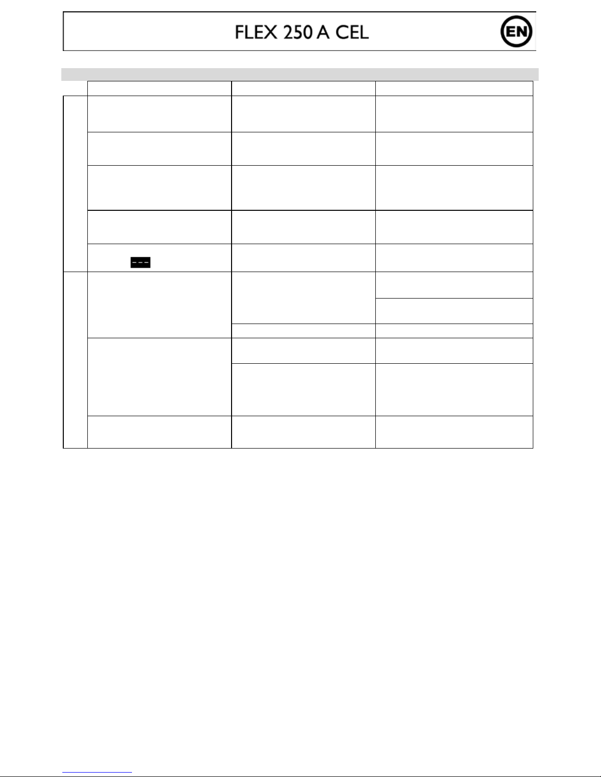
TROUBLESHOOTING
Anomalies
Causes
Remedies
MMA-TIG
The device does not deliver any
current and the yellow indicator
thermal default light
is on.
Thermal protection is active.
Wait for the end of the cooling
period, approx 2 minutes. The
indicator light turns off.
The display is on but the device
does not deliver any current.
The earth clam p or electrode
holder is not properly connected
to the unit.
Check the connections.
If, when the unit is on and you
put your hand on the welding
unit’s body, you feel tingling
sensation.
The welding unit is not correctly
connected to the earth.
Check the plug and the earth of
your electrical network.
The display is on but the device
does not deliver any current.
The cable of the earth clamp or
electrode hol der is not connected
to the welder.
Check the connections.
When starting up, the display
indicates .
The voltage is over the limit
440V +15%.
Have the electrical installation
checked.
TIG
Unstable arc.
Failure of the tungsten electrode.
Ensure the correct size of electrode
is being used.
Use a well prepared tungsten
electrode
Too important gas flow rate.
Reduce gas flow rate.
The
tungsten electrode oxidizes
and tarn
ishes at the end of the
weld.
Welding zone.
Protect welding zone against air
flow.
Fault coming from post-gas or
the gas has been stopped
prematurely.
Check and tighten all gas
connections . W ai t un til the elec trode
cools down before stopping the gas.
The electrode melts.
Polarity error.
Check that the earth c lamp is really
connected to +.
Page 15
15
BEZEICHNUNG
Wir freuen uns, dass Sie sich für ein Markengerät unserer Firma entschieden haben und danken Ihnen für das
entgegengebrachte Vertrauen. Bitte lesen Sie sorgfältig vor dem Erstgebrauch diese Betriebsanleitung .
Das FLEX 250A CEL ist ein tragbares, luftgekühltes Schweißinverter, konzipiert um Schweißarbeiten an
ummantelten- (MMA) und hitzebeständigen (WIG Lift) Elektroden bei Gleich strom (DC) durchführe n zu könne n. Im
MMA Modus k önnen alle gäng igen Rutil-, Edelstahl-, Guss-, basischen und zellulosehaltigen. Im WIG Modus ist es
möglich die meisten Metalle mit Ausnahme von Legierungen und Aluminium zu schweißen. Dieses Gerät ist
generatortauglich und gegen Überspannung geschützt.
ANSCHLUSS - INBETRIEBNAHME
• Das FLEX 250 A CEL ist ein mit « flexible Voltage » ausgestattetes Gerät, dass mit Netzspannungen zwischen
110V und 480V, einphasig oder dreiphasig (50-60 Hz), betrieben w erden ka nn. Die tats ächliche S tromaufna hme
(l1eff) ist auf dem Gerät als maximale Betriebsbedingung angegeben. Überprüfen Sie, dass die Netzspannung und
die Absicherung (Sicherung) kompatibel für die Anwendung des Gerätes ist.
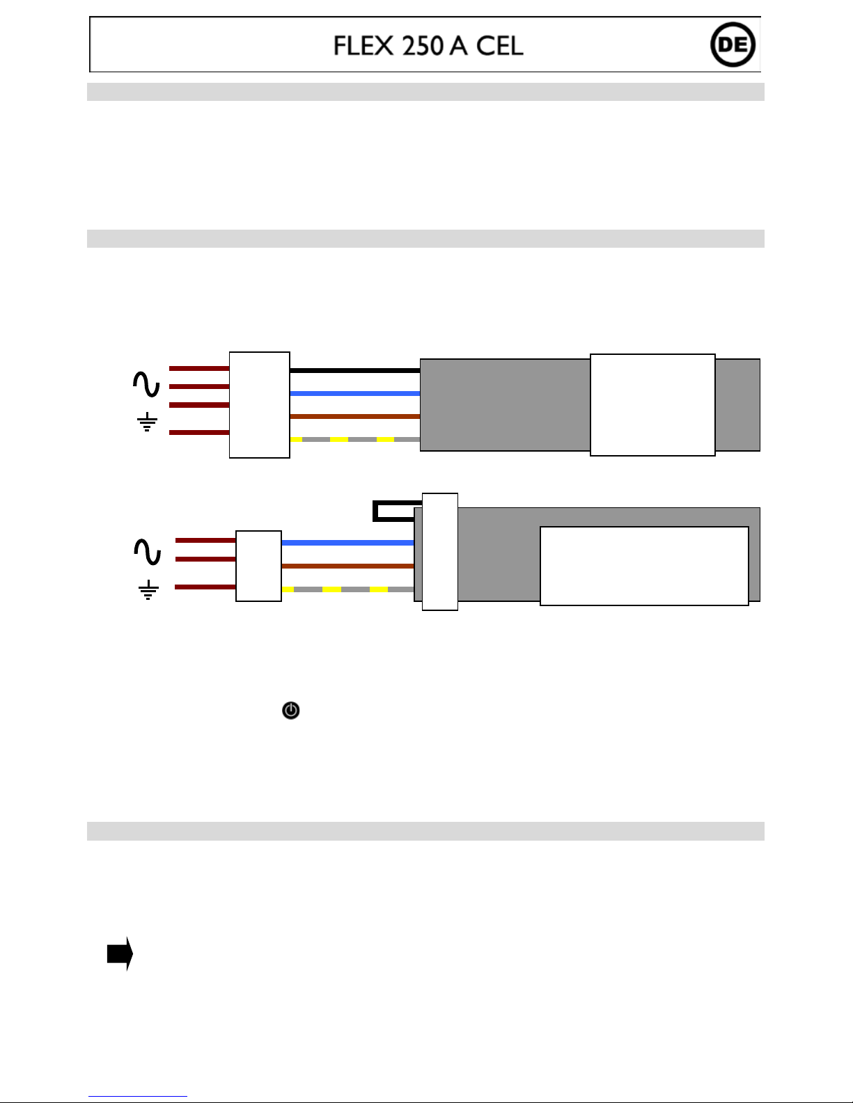
Anschlussdiagramm
3
+
Dreiphasiger Anschluss
2
+
Einphasiger Anschluss
Dem Gerät liegt ein Adapter für den Anschluss an eine einphasige Versorgung bei. Dieser darf
AUSCHLIESSLICH zu diesem Zweck verwendet werden! Bitte beachten Sie die geänderten
Leistungsdaten bei einphasigem Anschluss.
• Zum Starten drücken Sie die ( )
• Dieses Gerät ist K lasse A und ist für den industriellen und/ oder professionellen Gebrauch geeignet. In einem
anderen Umfeld ist die elektromagnetische Verträglichkeit schwieriger zu gewährleisten. Verwenden Sie das Gerät
nicht in Räumen, in denen sich in der Luft metallische Staubpartikel befinden, die Elektrizität leiten können.
• Das FLEX 250A CEL v erfügt über Einste llmöglichkeite n in Bezug auf den Netzansc hluss. Es wird e mpfohlen die
mitgelieferten Kabel zu verwenden
SCHWEISSEN MIT UMHÜLLTEN ELEKTRODEN (MMA MODUS)
• Schließen Sie Elektroden- und Massekabel an die entsprechenden Anschlüsse an. Beachten Sie die auf der
Elektrodenpackung beschriebenen Polaritätsangaben
• Beachten Sie die allgemeinen Regeln zur Unfallprävention beim Schweißen
• Ihr Schweißgerät ist mit drei spezif ischen Funktionen zur Verbesserung der Schweißeigenschaften au sgerüstet:
Hot Start (einstellbar, s. nachfolgender Abschnitt): Erhöht den Schweißstrom beim Zünden der
Elektrode
Arc Force (einstellbar, s. nachfolgend er Abschnitt): Erhöht kurzz eitig den Sc hweißstrom. E in mögliches
Festbrennen (Sticking) der Elektrode am Werkstück während des Eintauchens ins
Schweißbad wird verhindert.
Anti Sticking: Verbessert den Einbrand und verhindert mögliches Festbrennen
Auswahl der Betriebsart und Stromstärke:
- Wählen Sie mit der Drucktaste den MMA Modus aus
1- phase 1
2- phase 2
3- phase 3
4- Erde
1- phase 1
2- phase 2 ou neutre
3- Erde
Page 16

16
- Wählen Sie mit der Drucktaste die gewünschte Stromstärke (Anzeige ) aus
Konfiguration Hot Start und Arc Force:
FLEX 250 A CEL
Hot Start
0 90%
Arc Force
0 90% oder Elektrod entyp
Justieren Sie den Arc-Force von 0 bis 90 %, dann schalten Sie auf E letroden Modus « rut », « bas » oder « cel ».
Diese Modi sind optimierte Einstellungen für die verschiedenen Elektrodentypen.
Hinweis:
Niedriger Hot Start für dünne Metallbleche;
hoher Hot Start für schwer zu schweißende Metalle mit verschmutzen oder oxidierten Stellen.
Um Hot Start und Arc Force einzustellen, gehen Sie wie folgt vor:
Drücken Sie 3 Sek. lang die Taste
Stellen Sie den gewünschten Prozentsatz (Anzeige) mithilfe der Taste ein
Bestätigen Sie die gewünschte Einstellung mit der Taste
Stellen Sie den gewünschten Prozentsatz (Anzeige) mit Taste ein
Bestätigen Sie die gewünschte Einstellung mit der Taste
WIG KONTAKTZÜNDUNG
Verwenden Sie b eim WIG DC- Schweißen Argon- Schutzgas.
Um im WIG Modus zu sc hweißen, gehen Sie bitte wie folgt vor:
1. Schließen Sie die Massek lemme an der (+) Schweiß buchse an
Schließen Sie einen Brenner mit Ventil an der (-) Buchse an
2. Verbinden Sie die Brennergasleitung über den Druckminderer direkt an der Gasflasche.
Trennen Sie Überwurfmutte r und Flansch vo n der Brennerg asleitung, wenn diese nicht auf d en Druckmindere r
passen und fixieren Sie die Ga sleitung direkt am Gasnippel des Manometers
3. Wählen Sie mithilfe des Drucktasters den WIG Modus an
4. Stellen Sie den gewünschten Schweißstrom (Anzeige ) mithilfe des Drucktasters ein
5. Gehen Sie danach wie folgt vor:
a- Werkstück mit der
electrode berührer und
Brennertaster
b-
Brenner 2 bis 5mm über
dem Werkstück anheben
6. Zum Schweiße nd e :
Heben Sie den Brenner zwei Mal (auf-ab-auf-ab), um die Funktion „Automatisches Stromabsenken“ (s.
nachfolgender Abschnitt) zu aktivieren. Führen Sie diese Bewegung innerhalb von 4 Sek. 5-10mm über dem
Werkstück aus und schließen Sie das Gasventil erst, wenn der Lichtbogen erloschen ist und die Elektrode sich
abgekühl t ha t.
Automatische Stromabsenkfunktion mit Zeiteinstellung
Start der Funktion:
Am Ende des Schweißprozesses wird der Strom in definierter Zeit stufenlos heruntergefahren.
Diese Funktion hilft, Sprünge und Krater am Ende der Schweißnaht zu vermeiden.
Diese Funktio n ist zunächst inaktiv (Zeit 0 Sek.). Um sie zu aktivieren, gehen Sie bitte wie
folgt vor:
Page 17

17
1- Drücken Sie 3 Sek. lang die Taste
2- Stellen Sie die gewünschte Absenkzeit zwischen 1 und 10 Sek.
(Anzeige ) mit der Taste ein
3- Betästigen Sie die Gewünschte Einstellung mit der Taste
Empfohlene Schweißeinstellungen/ Elektrode schleifen
Strom (A)
Ø Elektrode (mm)
= Ø Zusatzdraht
Ø Düse
(mm)
Gasströmung
(Argon l/min)
0,5-5 10-130 1,6 9,8 6-7
4-8 130-200 2,4 11 7-8
Um einen optim alen Schweißverlauf zu gewährleisten, nutzen Sie nur Elektroden, welche nach folgendem Vorbild
geschliffen wurden:
d
l
ANSCHLUSS FÜR FERNSTEUERUNG
Die Fernregelung funktioniert im WIG- und im E-Hand-Modus.
Das FLEX 250A CEL verfügt über einen Anschl uss für eine Fernregel ung. Der passende 7-polige Stecker (Zubehör
Art.-Nr. 045699) ermöglicht Ihnen den Anschluss einer Fernbedienung (RC) oder Fußfernregelung (PED).
Verkabelung siehe Zeichnung:
Anschluss:
1- Gerät ansc halten
2- Fussfernreglung oder Handfernbedienung an das Gerät anschliessen
3- Die digitale Anzeige zeigt « NO » an
4- Mit den Tasten wählen Sie den Typ der Fernsteuerung aus:
No « RC » (Handfernbedienung / Remote Control) PEd (Fussfe r ns te ue rung)
5- Nach 2 Sekunden blinkt die digi tale Anzeige nicht mehr. Die Stromstärke in A m pere wird angezeigt.
Im Falle eines Fehlers die Fernsteuerung trennen. Mit „No“ zeigt das Gerät an, dass nichts angeschlossen ist.
Bemerkung: Diese Anzeige erscheint bei jedem Neu st art
Fernsteuerungsbetrieb
Hand Fernbedienung (Zubehör Art.-Nr. 045675) / Fussfernregler (Zubehör Art.-Nr. 045682) :
Die Fernbedienung ermöglicht die Fernsteuerung des Schweißstroms ab der minimalen Stromstärke (DC: 10 A /
MMA: 10A) bis zu d er durc h den Anw ende r eing estell ten max imale n Stro mstä rke . In die ser Einste llung si nd alle Modi
und Funktionen des Gerätes verfügbar und können reguliert werden.
THERMISCHE ÜBERWACHUNG & EINSCHALTDAUER
• Thermischer Überlastschutz: Lassen Sie das Gerät sich- je nach Umge bungs tempe ratur- 1 bis 5 min abkü hlen, bis
die Kontrollanzeige erlischt
• Lassen Sie das Gerät auch nach Schweißende einige Zeit am Stromnetz angeschlossen, damit sich das abkühlen
kann
Die JBDC-Schweißgeräte entsprechen in ihrer Charakteristik einer Konstantstromquelle. Die Einschaltd aue r entspric h t
wie unten beschrieben der Norm EN60974-1 (bei 40°C und einem 10min Zyklus):
L = 2,5 x d.
L
D: Start/Stop Kontakt
C: Masse
B: Regelung
A: + 5V
NB: Der Wert des Poti muss 10 KΩ sein
Ref.045699
Page 18

18
MMA
U1 = 110V U1 = 230V U1 = 400V
1~ 3~ 1~ 3~ 1~ 3~
30% 60% 100% 35% 60% 100% 41% 60% 100% 53% 60% 100% 40% 60% 100% 32% 60% 100%
140A 115A 90A 140A 125A 100A 200A 180A 150A 200A 190A 170A 250A 220A 190A 250A 200A 170A
25,6V 24,5V 23,6V 25,6V 25V 24V 28V 27,2V 26V 28V 27,6V 6,8V 30V 28,8V 27,6V 30V 28V 26,8V
TIG
U1 = 110V
U1 = 230V
U1 = 400V
1~
3~
1~
3~
1~
3~
60%
60%
100%
100%
60%
100%
80%
60%
100%
100%
60%
100%
65%
60%
100%
43%
60%
100%
140A 140A 110A 140A 140A 140A 200A 200A 180A 200A 200A 200A 250A 250A 220A 250A 225A 180A
15,6V 15,6V 14,4V 15,6V 15,6V 15,6V 18V 18V 17,2V 18V 18V 18V 20V 20V 18,8V 20V 19V 17,2V
INSTANDHALTUNG
• Die Instandhaltungsarbeiten dürfen nur von qualifiziertem Fachpersonal durchgeführt werden
• Nehmen Sie regelmäßig (mindestens 2 bis 3 Mal im Jahr) das Gehäuse ab und reinigen Sie das Innere des
Gerätes mit Pressluft. Lassen Sie regelmäßig Prüfungen des Geräts auf seine elektrische Betriebssicherheit von
qualifizier te m Fachperson al d urchführe n
• Trennen Sie vor dem Öffnen des Gerätes die Stromversorgung zum Gerät und warten Sie, bis der Ventilator sich
nicht mehr dreht. Im Gerät sind die Spannungen sehr hoch und deshalb ge fä h rl ich
• Prüfen Sie regelmäßig den Zustand der Netzzuleitung. Wenn diese beschädigt ist, muss sie durch den Hersteller,
seinen Reparaturservice oder eine qualifizierte P erson ausgetauscht werd en, um Gefahren zu vermeid en
• Verdecken Sie nicht die Lüftungsschlitze
HINWEISE - EMPFEHLUNGEN
• Beachten Sie die Angaben auf der Elektrodenverpackung für Schweißstrom und Polari tät.
• Entfernen Sie nach dem Schweißprozess d ie Elektrode aus ih rem Halter.
• Führen Sie regelmäßig die Wartungsarbeiten durch.
UNFALLPRÄVENTION
Lichtbogenschweißen kann gefährlich sein und zu schweren - unter Umständen auch tödlichen Verletzungen führen. Schützen Sie daher sich selbst und andere . Beachten Sie unbedingt die f olge nden
Sicherheitshinweise:
Lichtbogenstrahlung
Gesichtshaut und Augen sind durch ausreichend dimensionierte EN 175 konforme
Schutzschirme mit Spezialschutzgläsern nach EN 169 / 379 vor der intensiven
Ultraviolettstrahlung zu schützen.
Auch in der Nähe des Lichtbogens befindliche Personen oder Helfer müssen auf
Gefahren hingewiesen und mit den nötigen Schutzmitteln ausgerüstet werden.
Umgebung
Benutzen Sie da s Gerät nur in sauberer und gegen Nässeeinwirkung geschützter
Umgebung.
Feuchtigkeit
Stromversorgung
Achten Sie auf den Stromanschluss der jeweiligen Geräte. Keine Spannungsführenden
Teile berühren.
Transport
Unterschätzen Sie nicht das Gewicht der Anlage. Bewegen Sie das Gerät nicht
über Personen oder Sachen hinweg, und lassen Sie es nicht herunterfallen oder
hart aufse tz e n.
Verbrennungsgefahr
Schützen Sie sich durch geeignete trockene Schweißerkleidung (Schürze, Handschuhe,
Kopfbedeckung sowie feste Schuhe). Tragen Sie auch die Schutzbrille, wenn Sie
Schlacke abk lopfen. Sc hützen Sie a ndere dur ch nicht entz ündbare T rennwänd e. Nicht
in den Lichtbogen schauen und ausreichende Distanz halten.
Brandgefahr
Entfernen Sie alle ent flammbar en Prod ukte vom Schweiß platz un d arbeite n Sie nicht in
der Nähe von brennbaren Stoffen und Gasen
Schweißrauch
Die beim Schweißen entstehenden Gase u nd der Rauch sind gesundheitsschädlic h. De r
Arbeitsplatz sollte daher gut belüftet sein und der entstehende Rauch und die Ga se
müssen abgesaugt werden.
Page 19

19
Weitere Hinweise
Führen Sie Schweißarbeiten
-in Bereichen mit erhöhten elektrischen Risiken,
-in abgeschlo ss e ne n Rä um e n,
-in der Umgebung von entflammbaren oder explosiven Produkten
nur in Anwesenheit von qualifiziertem Rettungs- und/oder Fachpersonal durch. Treffen
Sie Vorsichtsmaßnahmen in Übereinstimmung mit "IEC 62081". Schweißarbeiten an
Gegenständen in erhöhter Position dürfen nur auf professionell aufgebauten Gerüsten
durchgeführt werden.
Halten Sie beim Arbeiten ausreichend Abstand zu Personen mit Herzschrittmacher! Personen mit
Herzschrittmacher dürfen mit dem Gerät nicht ohne ä rztliche Zustimmung arbeiten!
Das Gerät ist nicht geeignet für das Auftauen von Leitungen! Achten Sie beim Umgang mit Gasflaschen auf
sicheren Stand und Schutz des Flaschenventils! Beschädigte Flaschen stellen ein Sicherheitsrisiko dar!
HINWEISE ZUR REDUZIERUNG VON ELEKTROMAGNETISCHEN STÖRUNGEN
Allgemein
Es liegt in der Ver antwortung des Anwend ers dafür Sorge zu tragen, dass die Schweißausrüstung nach den Vorgaben
des Herstellers angeschlossen und verwendet wird. Liegen elektromagnetische Störungen vor, ist der Anwender
dafür verantwortlich dieses Problem mithilfe des technisc hen Supports des Herstellers zu beheben.
Prüfung des Schweißbereiches
Prüfen Sie vor Anschluss der Schweißausrüstung die Arbeits umgebung auf potentielle elektromagnetische Probleme.
a. Allgemeine Verkabelung, Steuerkabel, Fernmeldekabel und Datenleitungen über, unter und in direkter Nähe
des Schweißgerätes;
b. Radio/ TV Sende- und Empfangsgeräte;;
c. Computer und andere Kontrollgeräte;;
d. Empfindliche Anlagen für bspw. Sicherheitsüberprüfungen von industrieller Ausrüstung;
e. Gesundheitszustand (Herzschrittmache r, Hörgerät, usw.) der sich in der Umgebung des Gerätes befindlichen
Personen;
f. Geräte zum Kalibrieren und Messen;;
g. Unempfindlichkeit anderer externer Ausrüstung in der Nähe des Gerätes. Dies kann zusätzliche
Sicherheitsmaßnahmen erfodern.;
h. Tageszeit, zu der Schweiß- und andere Arbeiten durchgeführt w erden sollen;;
i. Berücksichtigung der Geräteumgebung, in Abhängigkeit der Gebäudestruktur und anderer Vorgänge am
Arbeitsplatz. Diese Umgebungsgrenze kann sich auch über die Grundstücksgrenzen erstrecken.
Hinweise zu den Methoden zur Reduzierung von elektromagnetischen Störungen
a. Hauptstromversorgung: Die Schweißausrüstung muss nach Herstellerangeben angeschlossen werden.
Treten Störungen auf, sind eventuell weitere Sicherheitsmaßnahmen, wie die Filterung der
Versorgungsspannung, notwe ndig.
b. Schweißkabel: Die Schweißkabel sollten so kurz wie möglich gehalten werden und gemeinsam auf bzw.
möglichst nahe am Bodenbereich verlaufen.
c. Schutz und Verstärkung: Selektiver Schutz und Abschirmung von anderen Kabeln und Geräten in der
Umgebung kann Störungsprobleme verringern. Das Maschinennetzkabel muss eventl. abgeschirmt werden. Die
Abschrirm ung muss der ge s amte n Kabellänge e nts pr e chen. Achten Sie darauf, dass das Schweißgerätegehäuse
extra geerdet ist.
d. Erdung des Werkstückes: Die Erdung des zu verschweißenden Werkstücks kann eventuelle
Störungsprobleme verringern. Sie sollte direkt bzw. über einen entsprechenden Kondensator erfolgen, je nach
landesspezifischen Vorgaben.
Page 20

20
FEHLERSUCHE
Fehler
Ursache
Lösungen
MMA-TIG
Das Gerät l iefert kein en
Schweißstrom und die gelbe
Übertemperaturanzeige leuchtet.
Der Übertemperaturschutz wurde
ausgelöst.
Warten Sie ca. 2 min bis der
Kühlvorgang abgeschlossen ist. Die
Anzeige erlischt danach.
Die Anzeige ist an, das Gerät liefert
jedoch keinen Schweißs trom.
Masseklem me ode r
Elektrodenhalter- Kabel sind nicht
korrekt mit dem Gerät verbunden .
Überprüfen Sie die Ans chlüsse.
Bei Berühru ng des Gerätes,
verspüren Sie ein leichtes Kribbeln.
Das Gerät ist nicht korrekt geerdet.
Überprüfen Sie den Netzansc hluss und
die Erdverbindung.
Die Maschine schweißt nicht
korrekt.
Polaritätsfehler.
Überprüfen Sie die vo m Hersteller
angegebene Polarität der Elektroden.
Beim Start zeigt das Display für
eine Sek .
Die Spannung liegt außerhalb des
Spannungstoleranzbereiches:
440V +15%
Überprüfen Sie die Netzspannung.
TIG
Unstabiler Lichtbogen.
Schlechte Wo lf ram-Elektrode.
Benutzen Sie eine Wolfram-Elektrode
von angemessener Länge.
Benutzen Sie eine sauber
angeschliffene Elektrode.
Zu hohe Gasströmung. Reduzieren Sie die Gasmenge.
Die Wolfram-
Elektrod e oxidiert un d
verfärbt sich am Ende des
Schweißvorgangs dunkel.
Schweißumgebung.
Schützen Sie die Schweißumgebung
vor Wind oder L uftzug.
Fehler wird durch Gasnachströmen
oder defektes Gasventil verursacht.
Überprüfen Sie die Gasanschlüs se.
Die Elektrode glüht.
Polaritätsfehler.
Überprüfen Sie ob die Masseklemme
an der (+) Buchse angeschlossen ist.
GARANTIE
Die Garantieleistung des Herstellers erfolgt ausschließlich bei Fabrikations- oder Materialfehlern, die binnen 24
Monate nach Kauf angezeigt werden (Nachweis Kaufbeleg). Nach Anerkenntnis des Garantieanspruchs durch den
Hersteller bzw. seines Beauftragt en erfolgen eine für den Käufer kostenlose Reparatur und ein kostenloser Ersatz
von Ersatzteilen. Der Garantiezeitraum bleibt aufgrund erfolgter Garanti eleistungen unverändert.
Ausschluss:
Die Garantieleistung erfolgt nic ht bei Defekten, die durch unsachgemäßen Gebra uch, Sturz oder harte Stöße sowie
durch nicht autorisierte Reparaturen oder durch Transportschäden, die in Folge des Einsendens zur Reparatur,
hervorgerufen worden sind. Keine Garantie wird für Verschleißteile (z.B . Kabel, Klemmen, Vorsatzscheiben etc.)
sowie bei Gebrauchsspuren übernommen.
Das betreffende Gerät bitte imm er m it Kaufb eleg un d kurz er Fe hle rbe schr eib ung a ussc hlie ßl ich über d en F achh ande l
einschicken. Die Reparatur erfolgt erst nach Erhalt einer schriftlichen Akzept anz (Unterschrift) des zuvor vorge legten
Kostenvoranschlags durch den Besteller. Im Fall einer G arantiele istung trägt JBDC aussc hließli ch die Kos ten für de n
Rückversand an den Fachhändler.
Page 21

21
DESCRIPCION
¡Gracias por su elección! Para sacar la mayor satisfacción de su aparato, lea atentamente lo siguiente:
Este aparato es de soldadura Inverter, portable y con ventilación, para la soldadura con electrodos recubiertos
(MMA) y con electrodos refractarios (TIG Lift) en corriente continua (DC). En modo MMA, permite soldar todo tipo de
electrodos: rutilo, inox, básico y hierro colado. En modo Tig, permite soldar la mayoría de los metales excepto
aluminio y sus aleaciones. Está protegido para el funcionamiento con grupos electrógenos.
ALIMENTACION-PUESTA EN MARCHA
• El FLEX 250 A CEL, dotado de un sistema « Flexible Voltage » se alimenta con una instalación eléctrica CON tierra
situada entre 110V y 480V monofásica o trifásica (50 - 60 Hz). La corriente efectiva absorbida (I1eff) para
condiciones de uso máximas está precisada sobre el equipo. Comprobar que la alimentación y sus protecciones
(fusible y/o disyuntor) sean compatibles con la corriente necesaria en uso.
Esquema de conexión
3
+
Conexión a un enchufe trifásico
2
+
Conexión a un enchufe monofásico
*¡Cuidado! En c aso de conexió n a una toma monofásica, el cable que no se usa se debe aislar para que
no entre nunca en contacto con los otros cables.
• La puesta en marcha se efectua apretando el botón ( )
• Estos aparatos son de Clase A. Son concebidos para un uso industrial o profesional. En un
entorno dist into, puede ser difícil asegurar la compatibilidad electromagnética, debido a las interf erencias
propagadas por conducción y por radiación. No utilizar en un entorno con polvo metálico conductor.
• El FLEX 250 CEL dispone de una regul aciόn de la corriente primaria, se aconseja utilizar los cables incluidos con
el aparato.
SOLDADURA CON ELECTRODO R EC UB IE RT O (M OD O MMA)
• Conectar lo s cab le s del portaelectrodo y de la pinza de m asa a lo s c one ctores. Respe tar las po lar idad es i nd icad as
sobre el embala je de los electrodos.
• Respetar las prácticas clásicas de la soldadura.
• Su aparato cuenta con 3 funcionalidades específicas de los Inverters :
El Hot Start procura una sobreintensidad al cebado (modo regulable, ver más abajo).
El Arc Force procura una sobreintensidad para evitar la pegadura cuando el electrodo entra en el baño.
(modo regulable, ver más abajo)
El Anti-Sticking le permite despegar facilmente su electrodo sin que se ponga roja en caso de
pegadura.
Puesta en marcha del modo MMA y regulación de la intensidad:
- Elegir la posición MMA con la tecla de selección
- Elegir la intensidad deseada (indicador ) mediante las teclas .
1- fase 1
2- fase 2
3- fase 3
4- tierra
1- fase 1
2- fase 2 o neutro
3- tierra
Page 22

22
Hot start & Arc force regulables:
FLEX 250 A CEL
Hot Start
0 90%
Arc Force
0 90% o tipo de electrodo
El arc force se puede regular de 0 a 90%, luego pasa por los modos de electrodos « rut », « bas » y « cel ».
Estos últimos modos son regulaciones optimas para los distintos tipos de electrodos.
Consejos :
Hot start bajo para chapas finas.
Hot start elevado para metale s difíc ile s d e soldar (partes sucias u oxidadas).
SOLDAD URA TIG LI FT (MODO TI G)
La soldadura TIG DC requiere una atmósfera gaseosa (Argon).
Para soldar con el TIG, seguir las etapas siguientes:
1. Conectar l a pi n za d e mas a so b re la po l ar idad positi v a (+).
2. Conectar u n a antorcha « con válvula » sobre la polaridad negativa (-).
3. Conectar el tubo de gas de la entorcha sobre la bombona de gas
4. Elegir la posición TIG con la tecla de selección .
5. Ajustar la intensidad deseada (indicador ) mediante las teclas .
Consejo : Elegir como base 30A / mm y ajustar según el metal a soldar.
6. Regular el caudal de gas con el manometro de la bombona de gas y abrir la válvula de la entorcha
7. Para cebar :
a. tocar con el electrodo el
metal a soldar
b. levantar el electrodo de 2
a 5mm del metal a soldar
8. Al final de la soldadura :
Levantar el arco 2 veces (arriba-abajo-arriba-abajo) para iniciar el desvanecimiento automático (ver
el paráfo de abajo). Este movimiento debe realizarse en menos de 4 seg., con una altura de 5 a
10mm. Después, cerrar la válvula de la entorcha para cortar el gas tras el enfriamiento del electrodo.
Desvanecimiento del arco automático con duración regulable
Activación de la función :
Al final de la soldadura, corresponde al tiempo necesario para una baja progresiva de la
corriente de soldadura hasta el paro del arco. Esta función permite evitar las grietas y
cráteres de finales de soldadura.
Por defecto, esta función no está activada (tiempo a 0 segundos). Para activarla, seguir
las etapas siguientes:
1- Pulsar 3 segundos la tecla de selección
2- Ajustar el tiempo de desvanecimiento deseado de 1 a 10 seg (indicador )
gracias a las teclas
4. Validar el valor deseado pulsando la tecla de selección .
Para regular el Hot Start & Arc Force, seguir las etapas siguientes:
Pulsar 3 segundos sobre la tecla de selección
Ajustar el porcentaje deseado (indicador ) mediante las teclas
Validar el valor deseado pulsando la tecla de selección
Ajustar el porcentaje deseado (indicador ) mediante las teclas .
Validar el valor deseado pulsando la tecla de selección
Page 23

23
Combinaciones aconsejadas / afiladura electrodos
Corriente
(A)
∅ Electrodo (mm)
= ∅ Hilo (metal de
aportación)
∅
Boquilla
(mm)
Caudal
(Argon l/mn)
0,5-5 10-130 1,6 9,8 6-7
4-8
130-200
2,4
11
7-8
Para un funcionamiento óptimo, se debe utilizar un electrodo afilado de este modo:
d
l
CONTROL A DISTANCIA
El control a distancia funciona en modo TIG y MMA.
Conectores
El FLEX 250A CEL tiene equipado un acoplamiento para un control a distancia. La clav ija específica de 7 puntos
(opción ref. 045699) permite conectar su control a distancia manual (RC) o a pedal (PEd).
Para el cablead o, seguir el esquema siguiente:
Conexión
1- Encender el aparato.
2- Conectar el pedal o el mando en la parte de delante del aparato.
3- El indicador digital muestra « No » (Nada ),
4- Seleccione el tipo de control a distancia con :
No (Nada) « RC » (Control remoto / mando a distancia) PEd (Pedal)
5- Tras dos segundos de inactividad, el indicador se detiene en el valor y vuelve a indicar la intensidad de soldado.
Nb : En caso de error, desconecte el control a distanci a, e l aparato le indic a que no hay nada : « No ». Tras ello,
volver a conectar el control a distancia y volver a realizar la selección.
Aviso : Esta opción se volvera a indicar en cada uso.
Funcionamiento
Comando a distancia manual (opción ref. 045675) / Pedal (opción ref. 045682)
El comm ando a distanc ia permite v ariar la co rriente de intens idad mínima (DC: 10ª / MMA : 10) a una i ntensidad
definida por el usuario.
En esta configuración, todos los modos y funcionalidades del aparato son accesibles y configurables.
PROTECCI ON TERMICA Y FAC T ORE S DE MARC HA
• Protección térmica: el indicador luminoso se enciende, la duración del enfriamiento es de 1 a 5 mn
dependiendo de la temperatura ambiente.
• Dejar el aparato conectado después de su us o para permitir su enfriamiento.
• El aparato descrito tiene una característica de salida de tipo « corriente constante ». Los factores de marcha
según la norma EN60974-1 están indicados en las tablas siguientes :
L = 2,5 x d.
L
D : Contacto del interruptor
C : Masa
B : Cursor
A : + 5V
Nb : El valor del potenciometro debe ser de 10 KΩ
Ref.045699
Page 24

24
MMA
U1 = 110V U1 = 230V U1 = 400V
1~ 3~ 1~ 3~ 1~ 3~
30% 60% 100% 35% 60% 100% 41% 60% 100% 53% 60% 100% 40% 60% 100% 32% 60% 100%
140A 115A 90A 140A 125A 100A 200A 180A 150A 200A 190A 170A 250A 220A 190A 250A 200A 170A
25,6V 24,5V 23,6V 25,6V 25V 24V 28V 27,2V 26V 28V 27,6V 6,8V 30V 28,8V 27,6V 30V 28V 26,8V
TIG
U1 = 110V
U1 = 230V
U1 = 400V
1~
3~
1~
3~
1~
3~
60%
60%
100%
100%
60%
100%
80%
60%
100%
100%
60%
100%
65%
60%
100%
43%
60%
100%
140A 140A 110A 140A 140A 140A 200A 200A 180A 200A 200A 200A 250A 250A 220A 250A 225A 180A
15,6V 15,6V 14,4V 15,6V 15,6V 15,6V 18V 18V 17,2V 18V 18V 18V 20V 20V 18,8V 20V 19V 17,2V
MANTENIMIENTO
• El mantenimiento deber ser realizado por una persona calificada.
• Cortar la alimentación desconectando el enchufe de la toma y esperar la parada del ventilador antes de
empezar las reparaciones sobre el aparato. Al interior, la tensión y la intensidad son elevadas y
peligrosas.
• A menudo (2 o 3 veces por año), sacar la tapa y desempolvar con una pistola de aire comprimido.
Aprovechar la ocasión para comprobar, por una persona calificada, el estado de las conexiones
eléctricas con una herramienta aislada.
• Controlar regularmente el estado del cable de alimentación. Si éste está dañado, tiene que ser
remplazado por el fabricante, su servicio postventa o por una persona con calificación similar, para
evitar cualquier peligro.
CONSEJOS
• Respetar las polaridades e intensidades de soldadura indicadas sobre los embalajes de electrodos
• Sacar el electrodo del portaelectrodo cuando el aparato no está en uso
• Dejar las aperturas del aparato libres para la aireación.
SEGURIDAD
La soldadura al arco puede ser peligrosa y causar heridas graves e incluso mortales. Es
imprescindible protegerse y proteger a los demás.
Respetar las instrucciones de seguridad siguientes :
Radiación del
arco
Protegerse mediante una máscara conforme a las normas EN 169 o EN 379.
Lluvia importante,
Vapor de agua,
Humeda
Utilizar su aparato en una atmósfera propia (grado de polución ≤ 3), de plano y a una
altura de no más de 1 metro de la parte a soldar. No utilizar bajo lluvia o nieve.
Choque eléctrico
Velar por respetar las instrucciones previas de conexiόn a la ali m e ntaciόn eléctrica. No
tocar las partes bajo tensión. Comprobar que la red de alimentación está adaptada al
aparato.
Caídas
El aparato no debe pasar por encima de personas u objetos.
Quemaduras
Llevar ropa de obra en tejido ig nifugado (algodón, mono de trabajo o vaqueros).
Trabajar con guantes de protección y un delantal de soldadura.
Proteger a los demás instalando biombos de protección ignífugos, o informándoles
de no mirar el arco y quedarse a distancia suficiente.
Riesgo de
incendio
Suprimir todos productos inflamables del área de trabajo. Las obras no pueden
realizarse en presencia de gas inflamable.
Humos
No inhalar los gases y humos de la soldadura. Utilizar en un medio ambiente
correctamente ventilado, con extractores adaptados si se suelda en el interior.
Page 25

25
Precauciones
suplementarias
Cualquiera operación de soldadura :
-en lugares en los cuales existen importantes riesgos de choques eléctricos,
-en lugares cerrados,
-en presencia de material inflamable o sujetos a riesgos de explosión
siempre tiene que ser sometida a la aprobación previ a de un “responsable
experimentado” y ejecutarse en presencia de personas formadas para intervenir en
caso de urgencia.
Es imprescindible aplicar las medidas técnicas de protecciones descritas en la
especificación técnica CEI/IEC 62081.
Está prohibido soldar en posición realzada, salvo si se utiliza una plataforma de seguridad.
Las personas con marcapasos ti e nen que visi t ar al médico ant es de utili z ar estos apar a t os.
No utilizar el apar at o para desh elar las cañerías
En modo TIG, manipular la bombona de gas con precauciones, existen riesgos si la bombona o
la válvul a de la bombon a e stán dañadas .
RECOMENDACIÓN PARA REDUCIR LAS EMI SIONES ELECTRO-MAGNETICAS
Generalidad
El usuario es re spons able de la ins talac ión y del uso del equipo según las instrucciones del fabricante. Si se detectan
perturbaciones electrom agnéticas, es responsabilidad del usuario resolver la situación según las recomendaciones
dadas en el manual de uso o con la asistencia técnica del fabricante.
Evaluación del área de soldadura
Antes de instalar su equipo, el usuario tendrá que evaluar los problemas electromagnéticos potenci ales que podr ían
intervenir en el área donde está prevista la instalación, en particular tendrá que tener en cuenta las indicaciones
siguientes:
a. Otros cableados, cableados de control, cableados telefónico s y de com unicació n: arriba, abajo y al l ado
del equipo ;
b. Receptores y transmisores radio y televisión ;
c. Ordenadores y otros equipos de control ;
d. Equipamientos críticos para la seguridad como mandos de seguridad de equipamientos industriales;
e. La salud de las personas que se encuentran a proximidad de la máquina, por ejemplo personas que
llevan un marcapasos, un audífono, etc… ;
f. Equipamientos para calibrar y medir ;
g. La inmunidad de otros equipos instalados en el lugar donde está el equipo. El usuario tendrá que
asegurarse que los demás equipos del lugar son compatibles entre ellos. Esto podrá requerir
precauciones suplementarias;
h. El tiempo del día durante el cual se tendrá que hacer funcionar el equipo;
i. La superficie del área que habrá que considerar en torno al equipo dependerá de la estructura de los
edificios y otr as actividades que se desarrollan en el lugar. El área considerada puede extenderse más
allá de los límites de las empresas.
Recomenda c i on es s ob re lo s mé todos de reducción de las emisiones electromagnéticas
a. Alimentación principal: El aparato de so ldadura tendrá q ue ser conectad o a la red de alime ntación
conforme a las recomendaciones del fabricante. En caso de interferencias, puede ser útil tomar
precauciones suplementarias filtrando la te nsió n d e al ime ntac ió n. Tambi én p uede ser útil blindar el cable
de alimen tac ión en las instalacio ne s fi j a s d e l ap ar at o de so ldadura, bajo bande jas metálicas o dispositivos
equivalentes. El blindaje tendrá que ser eléctricamente contenido en la longitud entera del cable. Tendrá
que ser directamente conectado al aparato de soldadura con un buen co ntac t o elé ctr ico e ntre la bande ja
metálica y la caja del aparato.
b. Cables de soldadura : Los cables deben ser lo más cortos posibiles. Agruparlos y, si es posible,
dejarlos en el suelo.
c. Protección y blindaje: La protección y el blindaje selectivo de otros cables y materiales en la zona
cercana puede limitar problemas de perturbación.
d. Soldado a ras del suelo: el soldado a ras del suelo puede limitar problemas de perturbación. Puede
realizarse directamente o via un condensador apropiado. Esta elección se hace según las
reglamentaciones nacionales.
Page 26

26
ANOMALIAS, CAUSAS, SOLUCIONES
Anomalias
Causas
Solución
MMA-TIG
El aparato no libera ninguna
corriente y el indicador luminoso
amarillo de defecto térmico está
encendido .
La protección térmica del
aparato se ha puesto en marcha.
Esperar el final del enfriamiento
(más o menos 2 mn). El indicador
luminoso se apaga
El indicador está encendido pero
el aparato no libera ninguna
corrriente.
El cable de la pinza de masa o
del portaelectrod o no está
conectado al aparato.
Comprobar las conexiones.
El aparato está enchufado. Al
poner la mano sobre la tapa, se
sienten picores.
La conexión con la tierra está
mal hecha.
Comprobar la toma de tierra de su
instalación
El aparato no suelda bien. Error de polaridad.
Comprobar la polaridad aconsejada
sobre el embala je del electrodo
Durante la puesta en marcha del
aparato, el indicador indica
.
La tensión de alimentación está
superior a 440 V (+15%)
Comprobar su red eléctrica o su
grupo electrógeno
TIG
Arco inestable.
Defecto del electrodo tungsteno.
Utilizar un electrodo tungsteno con
tamaño ade cuado
Utilizar un electrodo tungsteno
correctamente preparado
Caudal de gas demasiado alto. Disminuir el caudal de gas
El electrodo tungsteno se oxida y
se empaña al final de la
soldadura.
Area de la soldadura.
Proteger el area de soldadura contra
las corrientes de aire.
Problema de gas, o interupción
prematurada de gas.
Comprobar y apretar todos los
empalmes de gas. Esperar que el
electrodo se enfrie antes de cortar
el gas.
El electrodo se funde. Error de polaridad.
Comprobar que la pinza de masa
está bien conectada al +
Page 27

27
ОПИСАНИЕ
Благодарим вас за выбор аппарата нашей марки! Чтобы полностью использовать его возможности,
пожалуйста, изучите данную инструкцию :
FLEX 250 A CEL является малогабаритным сварочным инвертором со встроенным вентилятором для сварки
электродом с обмазкой (MMA) и тугоплавким электродом (TIG Lift) на постоянном токе (DC). При сварке МMA
аппарат позволяет варить любым видом электрода: с рутиловой обмазкой (электроды для сварки на
переменном токе), с основной обмазкой (электроды для сварки на постоянном токе), электродами для сварки
чугуна, электродами для сварки нержавеющей стали и др. В режиме Tig, он варит большую часть металлов за
исключением алюминия и его сплавов. Он может работать от электрогенератора .
ПИТАНИЕ – ЗАПУСК В РАБОТУ
• FLEX 250 A CEL оборудован системой « Flexible Voltage » и должен быть подключен к однофазной или
трехфазной электроустановке 110-480В С ЗАЗЕМЛЕНИЕМ (50 - 60Гц). Эффективный потребляемый ток
(I1eff) указан на аппарате для условий максимального использования. Убедитесь, что питание и защиты
(предохранитель и/или плавкий предохранитель) адаптированы для тока, необходимого для
использования аппарата.
Схема подключения
3
+
Подключение к трехфазной розетке
2
+
Подключение к однофазной розетке
*ВНИМАНИЕ! В случае подключения к однофазной розетке, неиспользуемый провод должен
быть изолирован таким образом чтобы он не касался других проводов.
• Запуск в работу осуществляется нажатием на кнопку ( )
• Этот аппарат относится к Классу A. Он создан для использования в промышленной и
профессиональной среде. В любой другой среде ему будет сложно обеспечить электромагнитную
совместимость из-за кондуктивных и индуктивных помех. Не использовать в среде содержащей
металлическую пыль-проводник.
• Так как регулировка FLEX 250A CEL на первичной цепи, советуем использовать кабели,
поставляющиеся в наборе с аппаратом
СВАРКА ЭЛЕКТРОДОМ С ОБМАЗКОЙ (РЕЖИМ МMA)
• Подключите кабель электорододержателя и зажима массы в коннекторы. Соблюдайте полярность
указанную на упаковке с электродами.
• Следуйте общепринятым правилам сварки.
• Ваш аппарат снабжен 3 функциями свойственными инвертору:
Hot Start (регулируемый режим, см ниже) выдает импульс высокого тока (по сравнению с током сварки) в
момент пожига дуги
Arc Force (режим регулируется, см ниже) выдает сверхток препятствующий привариванию электрода в
момент его погружения в жидкий металл
Anti-Sticking позволяет легко отделить электрод не вызывая его приваривания в случае замыкания
электрода на землю
Активирование режима MMA и регулировка интенсивности:
- Выбрать позицию MMA с помощью кнопки
1- фаза 1
2- фаза 2
3- фаза 3
4- земля
1- фаза 1
2- фаза 2 или ноль
3- земля
Page 28

28
- Отрегулировать желаемую интенсивность (индикатор ) с помощью кнопок .
Регулируемые Hot start и Arc force:
FLEX 250 A CEL
Hot Start 0 90%
Arc Force
0 90% или тип электрода
L’arc force регулируется от 0 до 90%, затем переходит на тип электрода, « rut », « bas » и « cel ». Данные
режимы являются оптимальными настройками для разного типа электродов.
Наш совет :
Слабый Hot start, для тонких листов металла – повышенный Hot start для трудно
свариваемых металлов (плохо очищенные или окисленные детали)
Для регулировки Hot Start иt Arc Force следуйте следующим этапам:
Нажать 3 секунды на кнопку
Укажите желаемое процентное соотношение (индикатор ) с помощью кнопок
Подтвердите выбранное значение нажатием кнопки
Укажите желаемое процентное соотношение (индикатор ) с помощью кнопок
Подтвердите выбранное значение нажатием кнопки
СВАРКА TIG LIFT (РЕЖИМ TIG) (АРГОНОДУГОВАЯ СВАРКА)
Сварка TIG DC (при постоянном токе) требует использования защитного газа (Aргон).
Для сварки в режиме TIG, следуйте следующим этапам:
1. Подключите зажим массы на положительную полярность (+).
2. Подсоедините горелку с вентилем к отрицательной полярности (-).
3. Подсоедините газовую трубку горелки к газовому баллону
4. Выберите позицию TIG с помощью кнопки .
5. Отрегулируйте желаемую силу тока (индикатор ) с помощью кнопок .
Отрегулируйте расход газа на редукторе газового баллона и отгоройте вентиль на горелке
7. Для пожига дуги:
a- коснитесь детали
электродом
b- поднимите электрод на 2-
5мм от свариваемой детали
Окончание сварки:
9. Поднять дугу 2 раза (вверх-вниз-вверх-вниз) чтобы спровоцировать автоматическое затухание (см
параграф ниже). Это действие должно занять минимум 4 секунды на высоте от 5 до 10мм. Затем
закройте вентиль горелки чтобы прекратить доступ газа после охлаждения электрода.
Автоматическое затухание дуги с регулируемой длительностью
Активация функции:
Данное действие соответствует времени необходимому для постепенного снижения сварочного тока при
окончании сварки для затухания дуги. Эта функция позволяет избежать образования трещин и кратеров при
окончании сварки. По умолчанию эта функция неактивна (= 0 сек). Для активации проделайте следующее:
Page 29

29
1. Нажмите на кнопку в течении 3 сек
2. Отрегулируйте желаемое время затухания от 1 до 10 сек (индикатор ) с помощью кнопок
3. Подтвердите выбранное значение нажатием кнопки .
Советуемые комбинации / затачивание электрода
Ток (A)
∅ Электрод (мм)
= ∅ проволока
(присад. металл)
∅ Сопло
(мм)
Подача газа
(Аргон
л/мин)
0,5-5
10-130
1,6
9,8
6-7
4-8
130-200
2,4
11
7-8
Для оптимального функционирования вы должны использовать электрод, заточенный следующим образом:
d
l
ДИСТАНЦИОННОЕ УПРАВЛЕНИЕ
Дистанционное управление работает в режимах TIG и MMA.
Подключение
Аппарат FLEX 250A CEL оснащен разъемом гнездового типа для подключения дистанционного управления.
Специальный штепсель с 7 штырями (опция арт. 045699) позволяет подключить ручное дистанционное
управление (RC) или ножное (PEd).
Для монтажа следуйте приведенной ниже схеме.
Подключение
1- Включите аппарат
2- Подключите педаль или дистанционное управление к передней панели аппарата.
3- На экране мигает « No » (Ничего),
4- Выберите нужный вам тип управления
с помощью кнопок :
No (Ничего) « RC » (Remote Control/дистанционное управление) PEd (Педаль)
5- После 2 секунд бездействия на экране останется выбранное значение, затем заново появится
интенсивность сварки
Примечание: если вы ошиблись, отсоедините дистанционное управление, аппарат покажет, что больше
ничего не
подключено: « No ». Затем подключите заново и выберите нужный тип управления.
Примечание: Этот выбор нужно будет повторять при каждом включении аппарата.
Принцип действия
Русчное дистанционное управление (опция арт. 045675) / Педаль (опция арт. 045682)
Ручное дистанционное управление мощность сварочного тока от минимальных значений (DC: 10A / MMA: 10А)
до тока, выбранного пользователем (на экране).
В этой конфигурации, все режимы и функции остаются доступными и регулируемыми.
ТЕРМОЗАЩИТА И ПРОДОЛЖИТЕЛЬНОСТЬ ВКЛЮЧЕНИЯ (ПВ%)
• Термозащита : лампочка загорается и аппарат остывает от 1 до 5 минут в зависимости от температуры
окружающей среды.
• Оставьте аппарат включенным после сварки для того, чтобы он остыл.
• Описанные аппараты имеют "постоянный ток" на выходе. Их продолжительность включения по норме
EN60974-1 указаны в нижеследующих таблицах :
L = 2,5 x d.
L
D : Контакт переключателя
C : Масса
B : скользящий контакт (движок)
A : + 5В
Примечание: величина на потенциометре
должна быть 10 K
Ref.045699
Page 30

30
MMA
U1 = 110V
U1 = 230V
U1 = 400V
1~
3~
1~
3~
1~
3~
30%
60%
100%
35%
60%
100%
41%
60%
100%
53%
60%
100%
40%
60%
100%
32%
60%
100%
140A 115A 90A 140A 125A 100A 200A 180A 150A 200A 190A 170A 250A 220A 190A 250A 200A 170A
25,6V 24,5V 23,6V 25,6V 25V 24V 28V 27,2V 26V 28V 27,6V 6,8V 30V 28,8V 27,6V 30V 28V 26,8V
TIG
U1 = 110V
U1 = 230V
U1 = 400V
1~
3~
1~
3~
1~
3~
60%
60%
100%
100%
60%
100%
80%
60%
100%
100%
60%
100%
65%
60%
100%
43%
60%
100%
140A 140A 110A 140A 140A 140A 200A 200A 180A 200A 200A 200A 250A 250A 220A 250A 225A 180A
15,6V 15,6V 14,4V 15,6V 15,6V 15,6V 18V 18V 17,2V 18V 18V 18V 20V 20V 18,8V 20V 19V 17,2V
УХОД И ОБСЛУЖИВАНИЕ
• Обслуживание аппарата должно производится только квалифицированным персоналом.
• Всегда отключайте аппарат от сети, дождитесь остановки вентиляторов. Токи и напряжения внутри
аппарата значительны и представляют опасность.
• Регулярно снимайте крышку аппарата и очищайте его от пыли. Пользуясь случаем, обратитесь к
кварифицированному специалисту для проверки контактов соединений с помощью изолированного
инструмента.
• Необходимо проверять регулярно состояние электрического шнура. Если электрический кабель
повреждён, то он должен быть заменён изготовителем, его послепродажным отделом или
квалифицированным персоналом, во избежание всякой опасности.
НАШИ СОВЕТЫ
• Соблюдайте полярности и токи, указанные на коробках с электродами.
• Выньте электрод из электрододержателя, когда аппарат не используется.
• Оставьте щели аппарата открытыми для свободного прохождения воздуха.
ТЕХНИКА БЕЗОПАСНОСТИ
Электродуговая сварка может быть опасна для здоровья и жизни.
Защитите себя и окружающих, примите меры против:
Излучений дуги
защитите себя с помощью маски, снабженной фальтрами, соответствующими
нормам EN 169 или EN 379.
Сильного дождя,
водяных паров,
влажности
Используйте ваш аппарат в чистой атмосфере (уровень загрязнения ≤ 3), на
плоской поверхности и не ближе, чем в 1 м от свариваемой детали.
Не использовать аппарат под дождём и снегом
Электроудара
Не касайтесь деталей под напряжением. Убедитесь, что используемая вами сеть
подходит для данного аппарата.
Падений
Не переносите аппарат над людьми или объектами.
Ожогов
Надевайте рабочую одежду из огнеупорной ткани (хлопок, джинсовая ткань или
спецодежда).
Работайте в защитных перчатках и несгораемом фартуке.
Защитите окружающих, установив несгораемые ограждения или попросите их не
смотреть на дугу и придерживаться безопасного расстояния.
Пожара
Удалите все воспламеняемые вещи из зоны сварки. Не работайте в среде горючих
газов.
Дыма
Не вдыхайте газы и дым, производимые сваркой. Использовать аппарат в хорошо
проветриваемом помещении, с искуственной вентиляцией, при сварке внутри
закрытого помещения.
Page 31

31
Дополнительные
Меры
Предосторожности
Любые сварочные работы :
-в помещениях с повышенным риском электрошока,
-в закрытых помещениях,
-около восламеняющихся или взрывчатых материалов,
должны быть всегда предварительно подтверждены ответственным специалистом и
реализованы в присутствии обученного персонала, для срочного вмешательства в
случае необходимости.
Технические меры безопасности, описанные в "Технических Характеристиках"
CEI/IEC 62081 должны быть соблюдены. Сварка в сверхвысоком положении
запрещена, кроме случаев с использованием защитных платформ.
Лица, использующие электрокардиостимуляторы, должны проконсультироваться у врача перед
работой с данными аппаратами.
Не используйте аппарат для размораживания канализаций.
При сварке TIG осторожно обращайтесь с газовым баллоном, существует опасность в случае
повреждения баллона или его вентиля.
РЕКОМЕНДАЦИИ ДЛЯ СНИЖЕНИЯ ЭЛЕКТРОМАГНИТНОГО ИЗЛУЧЕНИЯ
Общие сведения
Пользователь несет ответственность за установку и использование аппарата в соответствие с указаниями
производителя. При обнаружении электромагнитных излучений пользователь должен разрешить проблему,
следуя рекомендациям, указанным в инструкции, или с помощью технической поддержки производителя.
Оценка сварочной зоны
Перед установкой аппарата пользователь должен оценить возможные электромагнитные проблемы, которые
могу возникнуть в зоне, где планируется установка, в частности, он должен учитывать следующие моменты:
a. Не находятся ли другие кабели, контрольная проводка, телефонные и коммуникационные кабели
снизу, сверху или рядом с аппаратом;
b. Приемники и передатчики радио и телевидения;
c. Компьютеры и другое оборудование контроля;
d. Оборудование необходимое для безопасности. Например управление безопасностью
промышленного оборудования;
e. Здоровье людей, находящихся вблизи аппарата, например: люди пользующиюся
кардиостимуляторами, слуховыми аппаратами и т.п.;
f. Оборудование для калибровки и замера;
g. Устойчивость других аппаратов, находящихся в помещении, где используется аппарат.
Пользователь должен убедиться, что все аппараты в помещении совместимы между собой. Это
может потребовать принятия дополнительных мер предосторожности.
h. Погода в течении дня, когда будет использован аппарат;
i. Площадь рассматриваемой зоны вокруг аппарата зависит от структуры здания и других работ
производимых на этом месте. Рассматриваемая территория может простираться за пределы
предприятия.
Рекомендации по методике снижения электромагнитного излучения
a. Основное электропитание: сварочный аппарат должен быть подключен к электросети в
соответствии с рекомендациями производителя. При наличии помех необходимо принять
дополнительные меры предосторожности путем фильтрации напряжения питания. Кроме того,
может потребоваться защитить кабель аппарата либо металлическим желобом (в случае если
аппарат постоянно находится на определенном рабочем месте), либо похожим приспособлением.
Бронь должна быть электрически постоянной на всей длине кабеля. Она должна быть прикреплена
к аппарату с хорошим электрическим контактом между металлическим желобом и корпусом
аппарата.
b. Сварочные кабели: кабели должны быть максимально короткими. Объедините их и, если
возможно, оставьте лежать на полу.
c. Защита и бронь: выборочная защита и бронь других кабелей и материалов, находящихся в
окружающей среде, поможет ограничить проблему, связанную с помехами.
d. Заземление свариваемой детали: заземление свариваемой детали поможет ограничить
помехи. Оно может быть сделано напрямую или через подходящий конденсатор. Сделайте выбор в
соответствии с нормами вашей страны.
Page 32

32
AНОМАЛИИ, ВОЗМОЖНЫЕ ПРИЧИНЫ, ВАРИАНТЫ РЕШЕНИЙ
Аномалии
Возможные причины
Решения
MMA-TIG
Аппарат не выдает сварочный
ток, при этом горит желтая
лампа индикатора термозащиты
.
Сработала тепловая защита
аппарата.
Ждите охлаждения в течение
приблизительно 2 минут, до
выключения лампы индикатора.
Лампочка выкличится.
Дисплей горит, но аппарат не
подает ток.
Кабель зажима массы или
держателя электрода не
соединены с аппаратом.
Проверьте подключение сварочных
кабелей.
Аппарат включен. Вы ощущаете
покалывание при прикосновении
к корпусу.
Аппарат не заземлен.
Проверьте розетку и заземление
вашего аппарата.
Аппарат варит с трудом Ошибка полярности
Сверьте полярность с
рекомендациями на коробке с
электродами
При включении на дисплеи
высвечивается
Напряжение питания больше 440
В (+15%)
Проверьте электрическую проводку
или генераторную установку
TIG
Нестабильная дуга
Дефект вольфрамового
электрода
Используйте вольфрамовый
электрод подходящего размера
Используйте правильно подгото-
вленный вольфрамовый электрод
Слишком сильная подача газа Уменьшить подачу газа
Вольфрамовый электрод окисляется и тускнеет в конце сварки
Зона сварки.
Защитить зону сварки от сквозняков.
Проблема подачи газа, или газ
был отключен слишком рано
Проверить и затянуть все газовые
соединения. Подождать когда
электрод остынет и после этого
выключить газ.
Электрод плавится Ошибка полярности
Проверить, что зажим массы
подсоединен к +
Page 33

33
BESCHRIJVING
Hartelijk dank u voor uw keuze! Leest u, voor een optimaal gebruik van het apparaat, aandachtig het hier
opvolgende door :
Dit lasapparaat is een draagbare, enkelfase, geventileerde Inverter voor het lassen met MMA elektrode en met
boogontsteking elektrode (TIG Lift) in gelijkstroom (DC). In MMA is het lassen met alle soorten elektrode n mogelijk:
rutiel, basisc h, RVS, giet ijze r en c e ll ulose. In TIG is het lassen van meeste metalen mogelijk, behalve aluminium en
aluminiumlegeringen. De apparaten zijn beveiligd bij gebruik met een generator.
STROOMVOORZIENING - OPSTARTEN
• De FLEX 250 A CEL, uitgerust met een « Flexible Vo ltage » systeem, moet aangesloten worden op een enkelfase
of driefasen (50 - 60 Hz) GEAARDE elektrischeinstallatie, tussen 110V en 480V. De effectieve stroomafname
(l1eff) is aangegeven op het toestel voor maximaal gebruik. Controleer of de stroomvoorziening en zijn
beveiligingen (netzekering en/of uitschakelaar) compatibel zijn met de elektrische stroom die nodig is voor
gebruik.
Dit apparaat wordt geleverd zonder stekker.
Aansluitschema
3
+
Aansluiting aan een driefasen stekker
2
+
Aansluiting aan een enkelfase stekker
*PAS OP ! In geval va n aansluiting aan een enk elfase stekker, moe t het ongebruikt e snoer geïsoleer d
worden, zodat het nooit in contact komt met andere snoeren.
• Voor opstarten druk op ( )
• Dit klasse A lasapparaat is ontworpen voor professioneel of industrieel gebruik. I n een andere om geving kan het
vanwege gelei dingen of stralingen moeilijk zijn om elektromagnetische comptab iliteit te bereiken.
• Niet geschikt voor gebruik in ruimtes waar stroomgeleidend metaalstof aanwezig is.
LASSEN MET BEKLEDE ELEKTRODE (MMA)
• Sluit de kabel van de elektrodehouder en de massakabel aan aan de aansluitingen. Respecteer de polariteit zoals
aangegeven op de elektrode verpak ki ng.
• Volg de gebruik elijke lasregels op.
• Uw toestel is uitgerust met 3 specifieke Inverter-functies :
De H
OT START (instelbare modus, zie hieronder) geeft een hoge stroomintensiteit bij het begin van het
lassen.
A
RC FORCE (instelbare modus, zie hieronder) levert een korte verhoogde stroom, om het vastplakken van de
elektroden in het smeltbad te voorkomen.
A
NTI STICKING vergemakkelijkt het losmaken van de elektrode bij vastplakken zonder uitgloeien van de
elektrode.
Activeren van de MMA stand en instellen van de intensiteit :
- Kies de MMA stand met de selectie knop (houd deze 3 sec ingedrukt)
1- fase 1
2- fase 2
3- fase 3
4- aarde
1- fase 1
2- fase 2 of neutraal
3- Aarde
*
Page 34

34
- Stel de gewenst e intensiteit in (display met behulp van de knoppen).
Afstelbare Hot Start en Arc Force :
FLEX 250 A CEL
Hot Start 0 90%
Arc Force 0 90% of type elektrode
De Arc Force is instelbaar tussen 0 en 90% en gaat vervolgens over op de functies « rut », « bas » en « cel ». Deze
laatste funct ies zijn optimaal ingesteld voor de verschillende types elektroden.
Advies:
Lage Hot Start voor dunne platen.
Hoge Hot Start voor de moeilijk te lassen metalen (geoxideerde of vervuilde stukk en).
Om Hot Start en Arc Force in te stellen, volg de volgende stappen:
Druk op de selectieknop
Stel het gewenste percentage voor Hot Start in met behulp van de selectieknoppen
Druk op de selectie knop om de gewenste waarde in te stellen
Stel het gewenste percentage van Arc Force (display ) met behulp van de
selectieknoppen.
Druk op de selectie knop om de gewenste waarde in te stellen
TIG LIFT LASSEN (TIG STAND)
Bij TIG DC lassen moet altijd een beschermgas gebruikt worden (Argon).
Voor het TIG lassen, volg de volgende stappen:
10. Sluit de aardklem aan aan de positieve pool (+).
11. Sluit de toorts met reduceerventiel aan de negatieve pool (-).
12. Sluit de gasleiding aan de gasaansluiting van de gasfles.
Het is soms nodig om deze gasleiding te verkorten als de gasaansluiting niet past.
13. Kies de TIG positie met behulp van de selectieknop . (houd deze 3 seconden ingedrukt)
14. Stel de gewenste intensiteit in (display) met behulp van de kno ppen , volgens de dikte van het werkstuk
(30A/mm).
15. Regel eerst de gasstroom met de gasaan sl uiting van de gasfles, open daarna het venti el van de toorts.
16. Boogontsteking:
a- raak het te lassen
voorwerp met de elektrode
aan
b-
til de elektrode op 2 tot 5
mm vanaf het werk stuk
17. Aan het einde van lassen: Til 2 keer de lasboog op (hoog-laag-hoog-laag) o m de autom atisc he a fsluit in g in te
schakelen. Deze beweging moet gemaakt worden in minder dan 4 seconden, op een hoogte van 5 tot 10 mm.
Sluit daarna het ventiel van de toorts om de gastoevoer na het afkoelen van de elektrode te stoppen.
Instelbare downslope
Activering van de functie:
Dit correspondeert, aan het eind van het lasproces, aan de tijd die nodig is voor de geleidelijke downslope, tot het
verdwijnen van de lasboog. Deze functie maakt mogelijk om scheuren en kratervormig aan het einde van het
lasproces te voorkomen.
Deze functie is niet standaard ingeschakeld (OFF). Activeren van deze functie:
Page 35

35
1- Druk op de selectieknop
2- Stel de downslope tijd in van 1 tot 10 sec (display ) met de
knoppen
3- Druk op de selectieknop om de gewenste waarde in te st ellen.
Geadviseerde combinaties / elektrode slijpen
Lasstroom
(A)
∅
Elektrode (mm)
= ∅draad
(lastoevoegmateriaal)
∅
Buis
(mm)
Gasstroom
(Argon l/mn)
0,5-5 10-130 1,6 9,8 6-7
4-10
130-250
2,4
11
7-8
Voor optimaal gebruik slijp de elektroden als volgt:
d
l
AFSTANDSBEDIENING
De afstandsbediening werkt in TIG en MMA modus.
Connectiviteit
De FLEX 250A CEL is uitgerust met een stopcontact voor de afstandsbediening. Met de specifieke 7 punten stekker
(optioneel , art. code 045699) kunt u u w handmatige afs ta ndsbedieni ng (R C) of pedaal (PED ) aans l uiten.
Voor de bedrading volg onderstaande schema.
Aansluiting
1- Schakel het toestel aan
2- Sluit het pedaal of de afstandsbediening aan op de voorkant van het toestel.
3- Het display knippert en geeft "No" aan (Niets),
4- Kies uw type bediening met behulp van de knoppen:
Nee (Niets) "RC" (Afstandsbediening) PEd (Pedaal )
5- Na 2 seconden wachten blijft het display op de waarde staan, en geeft vervolgens de lasintensiteit aan
NB: In geval van een fout, koppel uw afsta ndsbediening af, h et toestel geeft aan dat er niets
aangesloten is: « No ». Sluit daarna de afstandsbediening weer aan en herhaal de selectie.
Opmerking : De keuze zal opnieuw getoond worden na iedere opstart.
Werking
Handmatige afstandsbediening (optioneel, art. cod e 0 45675) / Pedaal (optioneel, art. code 045682)
De handmati ge afstandsbedie ning kan worde n gebruikt om te wissele n van de minimale str oom (DC: 10A / MMA:
10) tot de gewenste stroom (display).
In deze configuratie zijn alle modi en functies toegankelijk en aanpasbaar.
THERMISCHE BEVEILIGING EN VERMOGENSFACTOR
• Thermische beveiliging: Het lampje gaat aan en de koeltijd is van 1 tot 5 mn, afhankelijk van de
omgevingstemperatuur.
• Laat het lasapparaat na het lassen aangesloten, zodat het kan afkoelen
• Hetbeschre ven apparaatheeft een uitgaande eigenschap van het typ e "constante str oom". De vermogensfactor
volgens de EN60974-1 norm is vermeld in de onde rst aande tabel:
L = 2,5 x d.
L
D : SwitchContact
C : Massa
B : Cursor
A : + 5V
Nb: de potentiom eter waarde moet 10 K zi jnΩ
Artikel
Page 36

36
MMA
U1 = 110V
U1 = 230V
U1 = 400V
1~
3~
1~
3~
1~
3~
30%
60%
100%
35%
60%
100%
41%
60%
100%
53%
60%
100%
40%
60%
100%
32%
60%
100%
140A 115A 90A 140A 125A 100A 200A 180A 150A 200A 190A 170A 250A 220A 190A 250A 200A 170A
25,6V 24,5V 23,6V 25,6V 25V 24V 28V 27,2V 26V 28V 27,6V 6,8V 30V 28,8V 27,6V 30V 28V 26,8V
TIG
U1 = 110V
U1 = 230V
U1 = 400V
1~
3~
1~
3~
1~
3~
60%
60%
100%
100%
60%
100%
80%
60%
100%
100%
60%
100%
65%
60%
100%
43%
60%
100%
140A 140A 110A 140A 140A 140A 200A 200A 180A 200A 200A 200A 250A 250A 220A 250A 225A 180A
15,6V 15,6V 14,4V 15,6V 15,6V 15,6V 18V 18V 17,2V 18V 18V 18V 20V 20V 18,8V 20V 19V 17,2V
ONDERHOUD
• Het onderhoud kan alleen door gekwalificeerd personeel g edaan worden.
• Haal de stekker eruit om de elektriciteitsvoorziening te onderbrekenen wacht tot de ventilator stilstaat
alvorens werkzaamheden op het apparaat te verrichten. De spanning en de stroomsterkte binnen het toestel
zijn hoog en geva ar li jk .
• De kap regelmatig (2 of 3 keer per jaar) afnemen en hem met een blazer stofvrij maken. Gebruik deze
gelegenheid om met geïsoleerd gereedschap ook de elektrische verbindingen te laten controleren door
gekwalificeerd personeel.
• Controleer regelmatig het elektrische snoer. Als dit snoer beschadigd is, moet het door de fabrikant, zijn
reparatie dienst of een gekwalific eerde technicus worden vervangen, om ieder gevaar te vermijden
ADVIES
• Respecteer de polariteit (+/-) en de lasstroom zoals aangegeven op de elektrode doos
• Haal de elektroden uit de elektrodehouder wanneer het apparaat niet gebruikt wordt .
• Laat de ventilatieopening vrij zodat de lucht gemakkelijk kan circuleren.
VEILIGHEID
Booglassen kan gevaarlijk zijn en ernstige en zelfs dodelijke verwondingen veroorzaken. Bescherm
uzelf en anderen.
respecteer de volgende veiligheidsmaatregelen
:
Straling van
elektrische boog
Bescherm uzelf met een masker dat uitgerust is met de filters EN 1 69 of EN 379.
Regen, stoom,
vochtigheid
Gebruik uw lasapparaat in een schone atmosfeer (verontreinigingsgraad ≤ 3), vlak en
op meer dan 1 meter afstand van het te lass en stuk. Niet gebruiken bij regen of
sneeuw.
Elektrische schok
Respecteer de a angegeven stroomvoorzi ening. Raak de stukken onder spanning niet
aan. Controleer of de netspanning geschikt is voor het toestel.
Vallen Til nooit het apparaat boven personen of dingen.
Brandwonden Draag brandwerende werkkleding (katoen, overall of jeans).
Gebruik beschermende handschoenen en een brandwerend schort.
Bescherm anderen door niet-ontvlambare schermen te insta lleren op de werkplek, of
door mensen te waa rschuwen om niet naar de boog te kijken en voldoen de afstanden
te houden.
Brand risico
Haal alle ontvlambare producten van de werkplaats weg. Werk nooit als ontvlambaar
gas aanwezig is.
Rook
Adem het lasgas en de rook nooit in. Werk in een goed geventileerde ruimte; in geval
van binnen lassen gebruik het lasrookafzuigsysteem.
Page 37

37
Voorzorgsmaatregelen
extra
Elke laswerk:
- in een omgeving met een verhoogd risico op elektrische schokken,
- in gesloten ruimtes,
- in aanwezigheid van ontvlambare of explosieve materialen, moet vooraf door een
"expert supervisor" worden geëvalueerd, en moet altijd uitgevoerd worden in
aanwezigheid van mensen die opgeleid zijn om in te kunnen grijpen bij noo d g e vallen.
De technische b eschermingsmaatregelen MOETEN worden get roffen zoals beschreven
in de TECHNISCHE BESCHRIJVING " CEI/IEC 62081 ".
Lassen in de hoogte is verboden, behalve als gebruik wordt gemaakt van de
veiligheidsplatforms.
Personen met een pacemaker moeten een arts raadplegen voor gebruik van het apparaat.
We raden het gebruik van deze lasapparaten evenwel af aan deze personen.
Niet geschikt voor het ontdooien van leidingen.
Bij TIG lassen, moet er voorzichtig met de gasfles omgegaan worden; het kan gevaarlijk zijn als de
fles of de flesklep beschadigd is.
AANBEVELINGEN VOOR REDUCEREN VAN DE ELEKTROMAGNETISCHE EMISSIES
Algemeen
De gebruiker is verantwoordelijk voor het installeren en gebruiken van het toestel volgens de instructies van de
fabrikant. Als elektromagnetische storingen worden geconstateerd, is het de verantwoordelijkheid van de gebruiker
van het om het probleem op te lossen, volgens de aanwijzingen in de handleiding, of met hulp van de technische
dienst van de fabrikant.
Evaluatie van de lasruimte
Voor het installeren van het apparaat, moet de gebruiker eerst de mogelijke elektromagnetische problemen die zich
in de werkruimte voor zouden kunnen doen evalueren. Er moet in het bijzonder rekening worden gehouden met de
volgende aanwijzingen :
i. Andere bedrading, kabels, telefoon- en communicatiekabels: boven, onder of naast het toestel;
j. Radio en televisie zenders en ontvangers;
k. computers en andere controle apparatuur ;
l. essentiële veiligheidsapparatuur zoals controles op de veiligheid van industriële apparatuur ;
de gezondheid van personen in de buurt van de machine, bijvoorbeeld personen met een pacemaker of
gehoorapparaat enz....;.
m. Ijk- en meetapparatuur ;
n. De immuniteit van andere machines waarnaast het apparaat gebruikt wordt. De gebruiker moet zich
ervan verzekeren dat alle apparatuur in de werkruimte compatibel is. Dit kan betekenen dat men andere
of meer veiligheidsmaatregelen moet nemen ;
o. het aantal uren per dag dat er laswerkzaamheden plaatsvinden ;
p. De grote van de ruimte moet bekeken worden en is afhankel ijk van de structuur van he t gebouw en
andere werk za amheden die i n he t ge b o uw pl aatsvinde n. De o m ge ving d ie in a c ht ge no m e n m o e t wo r den
kan groter zijn dan de begrenzing van het bedrijfspand.
Aanbevelingen om elektromagnetische emissies te reduceren
e. Stroomvoorziening: Het lasapparaat moet worden aangesloten op de stroomvoorziening zoals
aanbevolen door de fabrikant. In geval van interferenties, moeten additionele voorzorgsmaatregelen
getroffen worden zoals het filteren van de hoofdstroo m. Er k an over wogen w orden om de voe dingskabel
af te schermen in een metalen buis of een equivalent daarvan. De hele lengte van de kabel moet
elektrische afgeschermd zijn. Controleer ook de aansluiting van de kabel op het toestel.
f. Laskabels: De laskabels moeten zo kort mogelijk zijn. Ze moeten zo dicht mogelijk bij elkaar gehouden
worden, en indien mogelijk op de grond liggen.
g. Beveiliging en afscherming: Selectieve afscherming van andere kabels en materiaal kan problemen
voorkomen.
h. Aarding van het te lassen voorwerp: Aard het te lassen voorwerp. Sluit het onderdeel direct aan op
de aarde of via een c ondensator. De keuze van de aansluiting i s afhankelijk van de nationale regelgevin g.
Page 38

38
AFWIJKINGEN, OORZAKEN, OPLOSSINGEN
Afwijkingen
Oorzaken
Oplossingen
MMA-TIG
Lasapparaat levert geen stroom en
geel lampje van de thermische
beveiliging brandt
.
De thermische beveiliging slaat aan.
Wacht ongeveer 2 min tot het
lasapparaat af gekoeld is. Lampje
gaat uit.
Display staat aan maar het
lasapparaat levert geen stroom.
De kabel van de aardingsklem of
elektrodehouder is n i et goed
aangesloten.
Controleer de aansluiting en .
Het apparaat is aangesloten, een
tinteling is voelbaar als u het
plaatwerk aanraakt.
De aarde-aansl uiting is defect.
Controleer de stekker en aarding van
uw installati e.
Het toestel last niet goed. Verkeerde polariteit aansluiting
Controleer de polariteit aangegeven op
de elektrod e doos.
Bij het opstarten wordt volgende
aangegeven
De netspanning is te hoog (440V
+15%)
Controleer de elektri sche installatie of
de generator
TIG
Instabiele las boog
Defect komt vanuit de
wolfraamelektrode
Gebruik de goede maat
wolfraamelektrode
Gebruik een goed voorbereide
wolfraamelektrode
Te sterke gasstroom Reduceer de gasstroom
De wolfraamelektrode oxideert en
bezoedelt aan het einde van het
lasproces
Laszones Bescherm de laszone tegen tocht
Probleem met gas of te vroege
afsluiting van de gasstroom
Controleer en draai de
gasaansluitingen aan Wachten tot de
elektrode afkoel
t voor afsluiten van
gasstroom.
Elektrode smelt Verkeerde polariteit aansluiting
Controleer of de massakabel
aangesloten is aan de positieve pool
(+).
Page 39

39
DESCRIZIONE
Grazie per averci scelto! Per trarre il massimo di soddisfazione da questo dispositivo, si consiglia di leggere
attentament e quanto segue:
Questi dispositivi di saldatura Inverter, portatili, ventilati, sono progettati per la saldatura ad elettrodo rivestito
(MMA) e ad elettrodo refrattario (TIG Lift) in corrente co ntinua (DC). In MMA, saldano qualsiasi tipo di elettrodo :
rutilo, inox , ghisa, basico e c ellulosic o. In Tig, saldano la magg ior p arte de i mate riali tran ne l'allum inio e le ghe simili.
Sono protetti per il funzionamento sui motogeneratori.
ALIMENTAZIONE - ACCENSIONE
• Il FLEX 250 A CEL dotato di u n s istema « Fle xib le V o ltag e » è a lime n ta to da un' ins ta ll azio ne e le t trica conmessa a
terra compresa tra 110V e 480V monofase o trifase (50 - 60 Hz). La corre nte effe ttiv a assor bita (I 1eff) è indic ata
sul dispositivo per delle condizioni d'uso ottimali. Verificare che l'alimentazione e le protezioni (fusibili e/o
disgiuntore) siano compattibili con la corrente necessaria per l'uso. Questo dispositivo è fornito senza presa.
Schema di connessione
3
+
Connessione ad una presa trifase
2
+
Connessione ad una presa monofase
*ATTENZIONE ! In caso di connessione ad una presa monofase, il filo non utilizzatodev'essere isolato
per non entrare mai in contatto con gli altri fili.
• L'accensi one si effetua con una leggera pressione sul tasto ( )
• Questi disposi tivi sono di classe A. Sono stat i concepit i per l'uso in un ambie nte industr iale o professio nale. In un
ambiente diverso, potrebbe essere difficile assicurare la compattibilità elettromagnetica, a causa delle
perturbazioni condotte o irradiate.
• Non usare in un ambiente incui vi sia polvere mettallica conduttiva.
SALDATURA ALL'ELETTRODO RIVE STITO (MODO MMA)
• Collegare i cav i porta-elettrodo e il morsetto di m assa ai connettori. Rispettare le polari tà indicate sulle scatole
degli elettrodi.
• Rispettare le regole classiche di saldatura.
• Il dispositivo è dotato di 3 funzioni specifiche agli inverter:
La H
OT START (modo regolabile, cf qui sotto) fornisce una sovracorrente all'inizio della saldatura.
L’A
RC FORCE (modo regolabile, cf qui sotto) libera una sovracorrente che evita l'incollaggio quando
l'elettrodo entra nel bagno di fusione.
L'A
NTI-STICKING vi permette di scollare facilmente l'elettrodo senza farlo arrossire in caso di incollatura.
Attivazione del modo MMA e regolazione dell'intensità:
- Selezionare la posizione MMA con il selettore (premere per 3 secondi)
- Regolare l’intensità desiderata (schermo ) p er mezzo dei tasti.
1- fase 1
2- fase 2
3- fase 3
4- terra
1- fase 1
2- fase 2 o neutra
3- Terra
*
Page 40

40
Hot Start e Arc Force régolabili :
FLEX 250 A CEL
Hot Start 0 90%
Arc Force 0 90% o tipo d'elettrodo
L’arc force è r eg olabile d a 0 à 90 % po i passa su modo e le ttro do , « rut », « bas » et « cel ». Queste ultime mo da li tà
sono relle regolazioni ottimali per i differenti tipi d'elettrodi.
Consigli:
Hot Start debole per le lamiere sottili.
Hot Start elevato per i metalli difficili da saldare (pezzi sporchi od ossidati).
Per regolare l' Hot Start e l'Arc Force, seguire la procedura alla pagina seguente.
Premere il tasto selettore
Regolare la percentuale d'Hot Start desiderata (schermo ) per mezzo dei tast i
Confermare il valore auspicato premendo sul tasto selettore
Regolare la percentuale d’Arc Force o il tipo d'elettrodo desiderato (schermo ) per me zzo dei
tasti .
Confermare il valore auspicato premendo sul tasto selettore
SALDATURA TIG LIFT (MODO TIG)
La saldatura TIG DC richiede una protezione gas (Argon).
Per saldare in TIG, seguire la procedura sottostante:
18. Collegare il morsetto di massa alla polarità positiva (+).
19. Collegare una torcia « a valvola » alla polarità ne g a tiva (-).
20. Collegare il tubo del gas al manometro della bombola di gas.
Potrebbe essere necessario tagliare la parte anteriore del dado esagonale se quest'ultimo non è adatto al
riduttore di pressione
21. Selezionare la po siz io ne TIG con il selettore . (premere per 3 secondi)
22. Regolare l'intensità desiderata (schermo ) per mezzo dei tasti , a seconda dello spessore da saldare
(30A/mm).
23. Regolare il flusso di gas s ul r iduto re di pre ssione della b ombo la di gas, e in se gui to aprire la v alvol a dell a
torcia
24. Per innescare:
a- toccare l'elettrodo sul
pezzo da saldare
b-
sollevare l'elettrodo da 2 a
5 mm dal pezzo da saldare
25. A fine saldatura : sollevare 2 volte l'arco (alto-basso-alto-basso) per attivare l'evanescenza automatica (cf
paragrafo sottostante). Il movimento deve essere effettuato in meno di 4 secondi, su un'altezza compresa fra 5 e
10 mm. Poi chiudere la valvola della torcia per fermare il gas dopo il raffreddamento dell'elettrodo.
Evanescenza automatica dell'arco di durata regolabile
Attivazione della funzione:
Corrisponde al tempo necessario alla fine della saltatura per la discesa progressiva della corrente di saldatura fino
all'arresto dell'arco. Questa funzione permette di evitare fessurazioni e imperfezioni di fine saldatura.
Per impostazione predefinita questa funzione non è attiva (OF F). Per attivarla, procedere come segue:
Page 41

41
4- Premere il tasto di scelta
5- Regolare il tempo d'ev anescenza desiderato da 1 a 10 sec (schermo ) per mezzo dei
tasti
6- Confermare il valore desiderato premendo sul tasto .
Combinazioni consigliate / affilatura elettrodo
Corrente (A)
∅
Elettrodo (mm)
=
∅
filo (metallo di
apporto)
∅
Ugello
(mm)
Flusso
(Argo l/mn)
0,5-5 10-130 1,6 9,8 6-7
4-10
130-250
2,4
11
7-8
Per funzionare nelle migliori condizioni l'elett rodo deve essere affilato come segue:
d
l
COMANDO A DISTANZA
Il comando a distanza funziona in modo TIG e MMA.
Connettività
Le FLEX 250A CEL è dotato d'u na pr esa fem mina per c omando a dis tanz a. La pr ise mâle spé cifique 7 points (option
ref. 045699) permet d’y raccorder votre commande à distance manuelle (RC) ou à pédale (PEd).
Per il cablaggio seguire lo schema sottostante.
Connessione
1- Accendere il dispositivo
2- Connettere il pedale o telecomando sulla parte anteriore del dispositivo.
3- Lo schermo lampeggia mostrando «No» (Niente),
4- Sélectionner votre type de commande à l’aide des touches :
No (Niente) « RC » (Remote Control/ comando a distanza) PEd (Pedale)
5- Dopo 2 secondi di inattività, lo schermo si blocca sul valore e poi mostra l'intensità di saldatura
Nb: In caso di errore, scollegare il telecomando, e il dispositivo non mostrerà più nulla
non è collegato: «No». Poi ricollegare il telecomando e fare la scelta.
Nota : Questa scelta sarà richiesta ad ogni accensione.
Funzionamento
Comando a Di stanza.m a nu ale ( o pz io n e re f. 045675) / Pedale (opzione ref. 045682)
Il comando a distanza manuale permette di far variare la corrente dall'intensità mini (DC : 10A / MMA : 10)
all'intensità definita dall'utente (schermo).
In questa configurazione, tutte le modalità e funzionalità del dispositivo sono accessibili e parametrabili.
PROTEZIONE TERMICA E CICLI DI LAVORO
• Protezione termica: la spia si accende e la durata del raffreddamento va da 1 a 5 mn a seconda della
temperatura ambiente.
• Lasciare il dispositivo collegato al termine della saldatura per permetterne il raffreddamento
• Il dispositivo descritto ha un a caratteristic a di uscita di tipo "corrente costante". Suo ciclo di lavoro secondo la
norma EN60974-1 è indicato nella tabella seguente :
L = 2,5 x d.
L
D: Contatto del switch
C: Massa
B: Cursore
A: + 5V
Nb: il valore del potenziomentro deve essere di 10
Rif.045699
Page 42

42
MMA
U1 = 110V U1 = 230V U1 = 400V
1~ 3~ 1~ 3~ 1~ 3~
30% 60% 100% 35% 60% 100% 41% 60% 100% 53% 60% 100% 40% 60% 100% 32% 60% 100%
140A 115A 90A 140A 125A 100A 200A 180A 150A 200A 190A 170A 250A 220A 190A 250A 200A 170A
25,6V 24,5V 23,6V 25,6V 25V 24V 28V 27,2V 26V 28V 27,6V 6,8V 30V 28,8V 27,6V 30V 28V 26,8V
TIG
U1 = 110V U1 = 230V U1 = 400V
1~ 3~ 1~ 3~ 1~ 3~
60% 60% 100% 100% 60% 100% 80% 60% 100% 100% 60% 100% 65% 60% 100% 43% 60% 100%
140A 140A 110A 140A 140A 140A 200A 200A 180A 200A 200A 200A 250A 250A 220A 250A 225A 180A
15,6V 15,6V 14,4V 15,6V 15,6V 15,6V 18V 18V 17,2V 18V 18V 18V 20V 20V 18,8V 20V 19V 17,2V
MANUTENZIONE
• La manutenzione deve essere effettuata da una persona qualificata.
• Scollegare il cavodi alimentazione dalla presa e attendere l’arresto del ventilatore prima di lavorare sul
dispositivo. All'interno, le tensioni e l'intensità sono elevate e pericolose.
• Due o tre volte all'anno, togliere il coperchio e spolverare con una pistol a ad aria. Cogliere l'occasione per far
verificare le connessioni elettriche da personale qualificato.
• Controllare regolarmente lo stato del cavo di alimentazione. Se il cavo di alimentazione è danneggiato, esso
deve essere sostituito dal fabbricante, dal suo servizio post vendita o da una persona di qualifiche simili, per
evitare pericoli
CONSIGLI
• Rispettare le polarità (+/-) e l'intensità di saldatura indicate sulle scatole degli elettrodi
• Togliere l'elettrodo dal porta elettrodo quando il dispositivo non è in uso.
• Lasciare le aperture dell'aria del dispositivo libere per l'entrata e l'uscita d'aria.
SICUREZZA
La saldatura ad arco può essere pericolosa e causare ferite gravi o mortali. Proteggersi e proteggere gli
altri.
Rispettare le se guenti is tru zioni di sic ure zza
:
Radiazioni
dell'arco
Proteggetevi utilizzando una maschera munita di filtri conformi alla EN 169 o EN 379.
Pioggia, vapori
d'acqua, umidità
Uilizzare il vostro dispositivo in un'atmosfera pulita (grado d'inquinamento ≤ 3), su una
superficie piatta e a più di un metro dal pezzo da saldare. Non usare sotto la pioggia o la
neve.
Scarica elettrica
Rispettate le regole sull'alimentazione dei dispositivi citate in precedenza. Non toccare i pezzi
sotto tensione. Verificare che la rete di alimentazione elettrica sia adatta al dispositivo.
Cadute Non far passare il dispositivo su persone o oggetti.
Ustioni Usare abiti da lavoro in tessuto ignifugo (cotone, tuta da lavoro o jeans).
Lavorare con guanti di protezione e grembiule ignifugo.
Proteggere gli altri installando paraventi non infiammabili, avvertire di non guardare l'arco e
di stare abbastanza lontani.
Rischi
d'incendio
Togliere tutti i prodotti infiammabili dallo spazio di lavoro. Non lavorare in presenza di gas
infiammabile.
Fumi
Non inalare i gas e fumi di saldatura . Uti lizzare in un ambiente correttamente ventilato, con
estrazione d'aria forzata se si salda in ambienti chiusi.
Page 43

43
Precauzioni
supplementari
Qualsiasi operazione di saldatura:
- in luoghi che comportano maggiori rischi di scosse elettriche,
- in luoghi chiusi,
- in presenza di materiale infiammabile o che comporti rischi d'esplosione, deve sempre
sottostare all'approvazione di un "esperto responsabile", ed effettuata in presenza di persone
preparate ad intervenire in caso di emergenza.
I mezzi tecnici delle protezioni descritti nella Specificazione Tecnica CEI/IEC 6 2081 devono
essere ugualmente applicati.
La saldatura in posizione sopraelevata è proibita, tranne in caso d'uso delle piattaforme di
sicurezza.
I portatori di pacemaker devono consultare un medico prima di usare questi dispositivi.
L'uso di questo dispositivo è sconsigliato a queste persone.
Non usare il dispositivo per scongelare le tubature.
In saldatura TIG, maneggiare la bombola di gas con attenzione, poiché ci sono rischi se la bombola o
la valvola della bombola sono danneggiate.
CONSIGLI PER RIDURRE LE EMISSIONI ELETTROMAGNETICHE
Generalità
L'utente è responsabile dell'installazione e dell'uso del dispositivo secondo le istruzioni d'uso del fabbricante. Se
vengono riscontrate perturbazioni elettromagnetiche, è responsabilità dell'utente risolvere la situazione seguendo i
consigli descritti sul manuale d'istruzione o con l'assistenza tecnica del fabbricante.
Valutazione della zona di saldatura
Prima di installare l'apparecchio, l'utente dovrà valutare i potenziali problemi elettromagnetici che potrebbero
presentarsi nella zona dove è programmata l'installazione del dispositivo, in particolar modo prendendo in
considerazione le indicazioni che seguono:
q. Altri cablaggi, cablaggi di controllo, cavi telefonici e di comunicazione: sopra, sotto e accanto al
dispositivo;
r. ricevitori e trasmettitori radio e televisione;
s. computers e altre apparecchiature di controllo;
t. apparecchiature critiche per la sicurezza come ad esempio i controlli di sicurezza degli attrezzi industriali;
la salute delle persone che si trovano in prossimità del dispositivo, ad esempio personne che porta no un p ace make r,
apparecchi acustici, ecc.;
u. Dispositivi che servono alla calibrazione e alla misurazione;
v. l'immunità di altri apparecchi presenti nello stesso locale d'uso di questo dispositivo. L'utente dovrà
assicurarsi che tutti i dispositivi presenti nel locale siano compatibili fra di loro. Potrebbe essere
necessario prendere ulteriori precauzioni;
w. il tempo della giornata durante il quale il dispositivo dovrebbe funzionare;
x. L'area da considerare intorno al dispositivo dipenderà dalla struttura degli e difi ci e de lle attivi tà svol te s ul
posto. La zona presa in considerazione potrebbe estendersi al di fuori dei limiti delle aziende.
Consigli sui metodi di riduzione di emissioni elettromagnetiche
i. alimentazione principale: Il dispositivo di saldatura dovrà essere collegato ad una rete di
alimentazione in conformità ai consigli del fabbricante. In caso di interferenze, potrebbe essere prendere
delle precauzioni supplementari filtrando la tensione di alimentazione. Potrebbe essere utile schermare il
cavo d'alimentazione nelle installazioni fisse del dispositivo, con canaline metalliche o dispositivi
equivalenti. Il rivestimento dovrebbe essere elettricamente continuo su tutta la lunghezza del cavo.
Dovrebbe essere collegato al dispositivo con un buon contatto elettrico tra la canaletta metallica e il
dispositivo.
j. Cavi di saldatura: I cavi devono esser e i più corti possibili. Raggrupp arli e, se possibile, lasciarl i per
terra.
k. Protezi one e riv estimen to: La prote zione e il riv estimen to sele ttivo d i altri cavi e m ateri ali nel la zona
circostante potrebbero limitare i problemi di perturbazioni.
l. Messa a terra del pezzo da saldare: La messa a terra del pezzo da saldare potrebbe limitare i
problemi di perturbazioni. Potreb be essere fatto direttamente o tramite un condensatore appropriato.
Questa scelta è fatta a seconda delle regolamentazioni nazionali.
Page 44

44
ANOMALIE, CAUSE, RIMEDI
Anomalie
Cause
Rimedi
MMA-TIG
Lapparecchio non eroga corrente e
la spia gialla diprotezione t e rmi ca è
accesa .
La protezione termica del
dispositivo s i è attivata.
Aspettare la fine del periodo di
raffreddamento, circa 2 m in uti. La spia
si spegne.
Lo schermo è acceso ma il
dispositivo n on eroga nessuna
corrente.
Il cavo del morsetto di mass a o il
porta elettrodo non sono connessi
al dispositivo.
Verificare le connessioni.
Il dispositivo è alimentato, e si
possono sentire formicolii sulla
mano quando essa è in contatto
con la carrozzeria.
La messa a terra è diffettosa.
Controllare la presa e la messa a terra
del vostro impianto.
Il dispositivo salda male Errore di polarità
Verificare la polarità consigliata sulla
scatola dell'elettrodo.
All'accensione, il display indica
La tensione d’alimentazione è
superiore al limite (440V +15%)
Verificare l'impianto elettrico o il
motogeneratore
TIG
Arco instabile
Difetto prov eniente dall'elet trodo in
tungsteno
Usare un elettrodo in tungsteno di
taglia appropriata
Usare un elettrodo in tungsteno
correttamente preparato
Flusso di gas t roppo elevato Ridurre il flusso di gas
L'elettrodo in tungsteno si ossid a e
si annerisce alla fine della saldatura
Zona di saldatura.
Proteggere l a zona di saldatura cont ro
le correnti d'aria.
Problema di gas, o interruzione
prematura del gas
Controllare e stringere tutte le
connessioni gas. Aspettare che
l'elettrodo si raffreddi prima di
interrompere il gas.
L'elettrodo fonde Errore di polarità
Controllare c he il mo rse tt o di m assa sia
correttamente collegato al +
Page 45

45
DÉCLARATION DE CONFORMITÉ :
JBDC atteste que le poste de soudure FLEX 250A CEL est fabriqué conformément aux exigences des directives
Basse tension 2006/95/CE du 12/12/2006, et aux directives CEM 2004/108/CE du 15/12/2004.
Cette conformité est établie par le respect des normes harmonisées EN 60974-1 de 2005, EN 60974-10 de 2007 et
EN 50445 de 2008.
Le marquage CE a été apposé en 2016.
DECLARATION OF CONFORMITY :
The JBDCmmi FLEX 250A CEL described o n this manual com plies with the instruct ions of low v oltage 20 06/95/ CE of
12/12/2006, and the instructions of CEM 2004/108/CE of the 15/12/2004.
This conformity respects the standards EN60974-1 of 2005, EN 60974-10 of 2007 and EN50445 of 2008.
CE marking was added in 2016.
KONFORMITÄTSERKLÄRUNG
JBDC erklärt, dass die beschriebene Geräte in Übereinstimmung mit den Anforderungen der folgenden europäischen
Bestimmungen: Niederspannungsrichtlinie 2006/95/CE –12.12.2006 und EMV- Richtlinien 2004/108/ CE – 15.12.2004
elektromagnetische Verträglichkeit- hergestellt wurden. Diese Geräte stimmen mit den harmonisierten Normen
EN60974-1 von 2005, EN 60974-10 von 2007 und EN 50445 von 2008 überein.
CE Kennzeichnung: 2016
DECLARACION DE CONF ORMIDAD :
JBDC ce rtifica que los a parato s d e so l dad ura FLE X 2 50 A CEL s on fab ric ado s e n co nfo rmid ad co n las d irec tiv as b aj a
tensión 2006/95/CE del 12/12/2006, y las directivas compatibilidad electromecánica 2004/108/CE del 15/12/2004.
Esta conformidad está establecida por el respeto a las normas EN 60974-1 de 2005, EN 60974-10 de 2007 y EN
50445 de 2008.
El marcado CE fue fijado en 2016.
ДЕКЛАРАЦИЯ О СООТВЕТСТВИИ:
JBDC заявляет, что сварочные аппараты FLEX 250 A CEL произведены в соответствии с директивами
Евросоюза 2006/95/CE о низком напряжении от 12/12/2006, а также с директивами CEМ 2004/108/CE от
15/12/2004.
Данное соответствие установлено в соответствии с согласованными нормами EN 60974-1 2005 г, EN 60974-10
2007 г и EN 50445 2008 г.
Маркировка ЕС нанесенна в 2016г.
VERKLARI NG VAN O VERE ENSTEMMING:
JBDC verklaart dat het FLEX 250 CEL lasapparaat vervaardigd is conform de laagspanningsrichtlijnen 2006/95/CE
van 12/12/2006, en volgens de CEM 2004/108/CE normen van 15/12/2004.
Deze overeenstemming is opgesteld volgens de volgende normen: EN60974-1 van 2005, EN 60974-10 van 2007, EN
50445 van 2008.
De CE-markering is in 2016 toegebracht.
DICHIARAZIONE DI CONFORMITÀ:
JBDC attesta c he il dispositttivo di saldatura FLEX 250A CEL è fabbric ato in conform ità alle esigenze delle direttive
Bassa tensione 2006/95/CE del 12/12/2006, e alle direttive CEM 2004/108/CE del 15/12/2004.
Questa co nformità è s tabilita risp ettando le norme armo nizzate EN 6 0974-1 del 2005, EN 60974-10 del 2007 e EN
50445 del 2008.
Il marchio CE è stato apposto nel 2016.
25/10/2016 Nicolas BOUYGUES
Sas JBDC Président Directeur Général
134 BD des Loges
53941 Saint Berthevin
Page 46

46
SCHÉMA ÉLECTRIQUE / CIRCUIT DIAGRAM / SCHALTPLAN / DIAGRAMA ELECTRICO /
ЭЛЕКТРИЧЕСКАЯ СХЕМА / ELEKTRISCHE SCHEMA
FLEX 250A CEL
Page 47

47
PIÈCES DE RECHANGE/ SPARE PARTS / ERSATZTEILE/ RECAMBIOS / ЗАПЧАСТИ / RESERVE
ONDERDELEN
FLEX 250 A CEL
N°
1
Douilles / Connectors / Schweißbuchsen / Conectores / Коннекторы /
Fitting / Boccole
51469
2
Clavier/ Display / Anzeige / Teclado / Дисплей / Bedieningspaneel /
Tastiera
51914
3
Carte élect ronique / Electronic car d / Elektronikplatine / Tarjeta
electrónica / Электронная плата / Print plaat / Scheda elettronica
a 97258
b 97257
c 97256
d 97221
e 97335
4
Cordon secteur (3m) / Power cord (3m)/ Netzkabel (3m) / Cable de
conexión (3m) / Сетевой шнур (3M) / Netsnoer (3m) / Cavo corrente
(3m)
21504
5
Ventillateur / Fan / Ventilator / ventilador / Вентилятор / Ventilator /
Ventilatore
51021
6
Grille / Protec tive screen / Ventilator- Grill / rejilla / Решетка /
Afrastering / Griglia
51010
7
Pieds / Feets / Füsse / Pies / Ножки / Poten / Piedi
71143
8
Presse etoupe / cable seal / Kabeldurchführung / racor atornillado /
кабельный ввод / Wartel / Passacavo
71148
Page 48

48
ICÔNES/ SYMBOLS/ ZEICHENERKLÄRUNG / ICONOS/ ПЕРЕДНЯЯ ПАНЕЛЬ / ΣΥΜΒΟΛΑ /
PICTOGRAMMEN
A
Ampère Amp Ampere Amperio Ампер / Hertz
V
Volt Volt Volt Voltios Вольт / Booglassen met beklede elektrode (MMA – Manual
Metal Arc)
Hz
Hertz Hertz Hertz Hertz Герц / TIG lassen (Tungsten Inert Gaz)
Soudage à l’électrode enrobée (MMA – Manual Metal Arc Schweißen mit umhüllter Elektrode
(MMA) Schweißen mit umhüllter Elektrode (E-Handschweißen) Soldadura con electrodos
refractarios (TIG – Tungsten Inert Gas) Ручная дуговая сварка (MMA – Manual Metal Arc) /
Booglassen met beklede elektrode (MMA – Manual Metal Arc)
Soudage TIG (Tungsten Inert Gaz) TIG welding (Tungsten Inert Gas) Schweißen mit
Wolfram Elektrode (Wolfram Edelgas) Soldadura TIG (Tungsten Inert Gaz) Сварка TIG
(Tungsten Inert Gaz) / TIG lassen (Tungsten Inert Gaz)
Convient au soudage dans un environnement avec risque accru de choc électrique. La s our ce de
courant elle-même ne doit toutefois pas être placée dans de tels locaux. Adapted for welding in
environment with increased risks of electrical shock. However, the welding source must not be
placed in such places. Schutz gegen Risiko von elektrischen Schlag. Das Schweißgerät darf nicht
direkt auf de m S chweißwerkstück gestellt warden. Adaptado a la soldadura en un entorno que
comprende riesgos de choque eléctrico. La fuente de corriente ella misma no debe estar situada
dentro de tal locales. Подходит для сварки в среде с повышенной опасностью удара
электрическим током. Тем не менее не следует ставить источник тока в такие помещения. /
Geschikt voor het lassen in een ruimte met verhoogd risico op elektrische schokken. De
voedingsbron zelf moet echter niet in dergelijke ruimte worden geplaatst.
IP21
Protégé contre l’accès aux parties danger euses avec un doigt, et contre les chutes ver ticales de
gouttes d'e a u Prote c te d against rai n and aga in s t fingers acce s s to dang e r o us parts Geschützt
gegen Regen und das Berühren gefährlicher T eile mit den Fingern. protegido contra el acceso a
partes peligrosas con el dedo, y contra las caídas verticales de gotas de agua Аппарат защищен
от доступа пальцев в опасные зоны и от вертикального падения капель воды / Beveiligd tegen
toegang tot gev aarlijke delen met een vinger, en tegen verticaal vallende waterdr uppels.
Courant de soudage continu Welding direct current Gleichschweißstrom La corriente de
soldadura es continua Сварка на постоянном токе / Continue lasstroom
Alimentati on électrique monophasée 50 ou 60Hz Single phase power supply 50 or 60Hz
Einphasiege Netzspannungsversorgung 50 oder 60 Hz Alimentación eléctrica monofásica 50 o 60
Hz Однофазное напряжение 50 или 60Гц / Enkel fase elektrische voeding 50Hz of 60 Hz.
Alimentation électrique triphasé 50 ou 60Hz Three phase power supply 50 or 60Hz
Dreiphasiege Netzspannungsversorgung 50 oder 60 Hz Alimentación eléctrica trifásica 50 o 60 Hz
Трёхфазное напряжение 50 или 60Гц / Driefasig elektrische voeding 50Hz of 60Hz.
Uo
Tension assignée à vide Rated no-load voltage Leerlaufversorgungspannung Tensión
asignada de vacío Напряжение холостого хода Znamionowe napięcie jałowe Τάση εν
κενώ / Nullastspanning
U1
Tension assignée d’alimentation rated supply voltage Ve r so r gungs s p a nn un g unter
Belastung. Tensión de la red Напряжение сети / Nominale voedingsspanning
I1max
Courant d’alimentation assigné maximal (valeur efficace) Rated maximum supply current
(effective value) Maximaler Versorgungsstrom (Effektivwert)
Corriente maxima de alimentacion
de la red Максимальный сетевой ток (эффективная мощность) / Maxim ale no m inale
voedingsstroom (effectieve waarde)
Page 49

49
I1eff
Courant d’alimentation effectif maximal Maximum effective supply current Maximaller
tatsächlicher Versorgungsstrom Corriente de alimentación efectiva maxima Максимальный
эффективный сетевой ток / Maximale effectieve voedingsstroom
EN 60974-1
L’appareil respecte la norme EN60974-1 The device complies with EN60974-1 standard relative
to welding units Die Normen EN60974-1 für Schweißanlagen El aparato está conforme a la
norma EN60974-1 referente a los aparatos de soldadura Аппарат соответствует европейской
норме EN60974-1 / Dit toestel voldoet aan de EN60 974-1 norm
Convertisseur monophasé ou triphasé transformateur-redresseur Single phase or tri phase
inverter, converter-rectifier Ein- oder dreiphasiger Inverter, Umwandler-Gleichrichter
Convertidor monofásico o trifásico transformador-rectificador Однофазный или трёхфазный
инвертор, с трансформацией и выпрямлением. / Enkel fase omvormer of een driefasen
transformator-gelijkrichter
@40°C
X
/10min
…%
X : Facteur de marche à …% X : duty factor at …% X : Einschaltdau er Faktor ...% X :
Factor de funcionamiento de …% X : Продолжительность включения …% / X:
Vermogensfac tor bij ...%
Nombre d'électrodes normalisées soudables en 1 heure, à 20°C, avec un temps d'arrêt de 20 s.
entre chaque électrode
Number of standardized electrodes weldable during 1 hour at 20°C, with a
delay of 20 s. between each electrode. Anzahl der Standard-Elektroden, die in 1 Stunde bei 20°C
geschweißt werden können mit einer Pause von 20 s zwischen jed er Elektrode Cantidad de
electrodos norm alizados soldabl es en 1 hora, a 20°C, inclu yendo una parada de 20 seg. entre cada
electrodo Количество стандартных электродов использованных за 1 час при 20°C с 20-ти
секундными перерывами между электродами. /
Aantal gestandaardiseerde elektroden lasbaar in 1
uur bij 20 ° C met een p auze van 20 s. tussen elke elektrode
Nombre d'électrodes normalisées soudables en 1 heur e en continu, avec 20 secon des entre
chacune, divisé par le nombre d'électrodes soudables dans les mêmes conditions sans disjonction
thermique. Number of standardized electrodes weldable over 1 hour of continuous work, divided
by the number of electrodes weldable in the same conditions without thermal shutdown
Elektroden Anzahl die inerhalb ein er Arbeitsstunde verschweißt werden können, geteilt durch
Elektroden- Anzahl die tatsächlich verschweißt sind (Abkühlphasen des Geräts) Cantidad de
electrodos normalizados soldables en 1 hora de manera continua, a 20°C, dividida por la quantidad
de electrodos soldables en condiciones identicas sin disyunción térmica. . Количество
стандартных электродов, использованных за 1 час в непрерывном режиме с 20-ти секундными
перерывами между электродами, поделенное на количество электродов, которые можно
сварить при тех же условиях, но без перегрева. / Aantal gestandaardiseerde e
lektroden lasbaar in
1 uur continu met 20 seconden tussen elke elektrode gedeeld door het aantal elektroden lasbaar bij
dezelfde omstandigheden zonder thermische uitschakeling.
I2
…
%
I2 : courant de soudage conventionnnel correspondant I2 : corresponding conventional
welding current I2: Sekundär Strom I2 : Corrientes correspondientes I2 :
Соответствующий условный сварочный ток / I2 : overeenkomstige conventionele lasstroom
U2
…
%
U2 : Tensions conventionnelles en charges correspondantes U2 : conventional voltages in
corresponding load U2 : Sekundär Spannung U2 : Tensiones convencionales en carga U2
: Соответствующие условные напряжения под нагрузкой / U2 : conventionele spanning in
corresponderen de belasting
Circuit de correction du facteur de puissance Power factor corector circuit included PFC
Netzoberwellenfilter. Circuito de correción de factor de potencia integrado Цепь коррекции
коэффициэнта мощности / Correctie schakeling van vermogens factor
Ventillé Ventilated Ventilator Ventilado Содержит встроенный вентилятор /
Geventileerd
Page 50

50
Appareil conforme aux directives européennes The device complies with European Directive
Das Gerät ist kompatibel mit Europäischen Normen El aparato está conforme a las no r mas
europeas. Устройство соответствует европейским нормам / Het toestel is in overeenstemm ing
met de Europese richtlijnen.
Conforme aux normes EAC (Russie)
Conform to standards EAC (Russia) Das Gerät ist conform mit EAC(Rußland) Normen
Conforme a la no rm as EAC (Rusia) Продукт соответствует стандарту России (ЕАС) /
Overeenstemming met de EAC norm (Rusland).
L’arc électrique produit des rayons dangereux pour les yeux et la peau (protégez-vous !) The
electric arc produces dangerous rays for eyes and skin (protect yourself !) Der Lichtbogen
erzeugt, gefährliche für die Augen und Haut, Strahlen (Schützen Sie sich!) El arco produce rayos
peligrosos para los ojos y la piel (¡ Protegase !) Электрическая дуга производит опасные лучи
для глаз и кожи (защитите себя!) / De elektrische boog veroorzaakt gevaarlijke stralen voor ogen
en huid (besche rm uz e lf! )
Attention, souder peut déclencher un feu ou une explosion . Caution, welding can produce fire
or explosion . Achtung. Schweißen kann Feuer oder Exp losion verursachen. Cuidado, soldar
puede iniciar un fuego o una explosión. Внимание! Сварка может вызвать пожар или взрыв. /
Let op, het lassen kan brand of explosie veroorzaken.
Le dispositif de déconnexion de sécurité est constitué par la prise secteur en coordination avec
l'installation électrique domestique. L'utilisateur doit s'assurer de l'accessibilité de la prise. . The
mains disconnection mean is the mains plug in combination with the house installation. Accessibility
of the plug must be guaranteed by user. Die Stromunterbrechung erfolgt durch Trennen des
Netzsteckers vom häuslichen Stromn etz. Der Gerätanwender sollte den freien Zugang zum
Netzstecker im m er gewährleisten El dispositivo de desconección de seguridad se const ituye de la
toma de la red electrica en coordinación con la instalación eléctrica doméstica. El usuario debe
asegurarse de la accesibilidad del enchufe. Система отключения безопасности включается
через сетевую штепсельную розетку соответствующую домашней электрической установке.
Пользователь должен убедиться, что розетка доступна / De veiligheid ontkoppeling van het
apparaat bestaat uit de stekker samen met de elektrische in stallatie. De aansluiting van he t to e s te l
moet toegankelijk zijn.
Mise en veille/mise en marche standby/On Schalter Bereit/ Ein standby/ puesta en
marcha Включить/Режим ожидания / Aan/uit knop
Attention ! Lire le manuel d’instruction avant utilisation Caution ! Read the user manual
Achtung ! Lesen Sie die Betriebsanleitung. Cuidado, leer las instrucciones de utilización.
Внимание ! Читайте инструкцию по использованию / Let op! Lees aandachtig de handleiding.
Produit faisant l'objet d'une collecte sélective- Ne pas jeter dans une poubelle domestique !
Separate col lection required – Do not throw in a domestic dustbin Getrennt entsorgen.Nicht mit
Hausmüll entsorgen. Este aparato es objeto de una recolección selectiva. N o debe ser tirado en
en cubo doméstic o. Продукт требует специальной утилизации. Не выбрасывать с бытовыми
отходами. / Afzonderlijke inzameling vereist. Gooi het apparaat niet bij het huishoudelijk afval!
Information sur la température (protection thermique) Thermal protection information.
Information zur Temperatur (Thermoschutz) Información de la temperatura (protección térmica)
Информация по температуре (термозащита) / Informatie over de temperatuur (thermische
beveiliging)
 Loading...