


THERMO 500
SHORTWAVE THERAPY UNIT
USER MANUAL
GEBRUIKERSHANDLEIDING
GEBRAUCHSANWEISUNG
MODE D’EMPLOI
EN - NL - DU - FR
GymnaUniphy NV
Pasweg 6a, 3740, Bilzen, Belgium
Tel. +32 89/ 510.510 fax +32 89/ 510.511
www.gymna-uniphy.com E-mail: info@gymna-uniphy.com
Your supplier is:

Manufacturer:
Uniphy Elektromedizin GmbH & Co. KG
Neuendorfstrasse 19 b / D-16761 Hennigsdorf - Germany
Tel.: +49 (0) 3302 5044-0 / Fax: +49 (0) 3302 5044-99
Email: info@uniphy-elmed.com
Internet: www.uniphy-elmed.com

ENGLISH......................................................................................................................................... 11
NEDERLANDS ............................................................................................................................... 43
DEUTSCH........................................................................................................................................ 77
FRANÇAIS .................................................................................................................................... 109

INTRODUCTION.......................................................................................... 11
1 OPERATION ELEMENTS AND SYMBOLS .................................... 12
1.1 INTRODUCTION ..................................................................................12
1.2 OPERATION ELEMENTS AND SYMBOLS ..............................................12
2 IN GENERAL......................................................................................... 15
2.1 USE OF HIGH-FREQUENCY HEAT THERAPY ........................................ 15
2.2 THE APPLIANCE ................................................................................. 15
2.3 ELECTRODE ARMS ............................................................................. 15
2.4 ELECTRODES...................................................................................... 16
2.5 CONTACT-CONTROL IN CASE THE DISTANCE BETWEEN THE
THERMOPLODES AND THE SKIN IS TOO BIG................................................... 16
2.6 EUROPEAN DIRECTIVE FOR MEDICAL DEVICES 93/42/EEC -
MEDICAL DEVICES DIRECTIVE (MDD) ........................................................ 17
3 OPERATION.......................................................................................... 18
3.1 CHECK ON DELIVERY......................................................................... 18
3.2 CURRENT CONNECTION ..................................................................... 18
3.3 SWITCHING ON................................................................................... 18
3.4 FUNCTIONAL TEST .............................................................................19
3.5 SELECTION OF LANGUAGE .................................................................19
3.6 SENDING / SHIPPING (TRANSPORT)....................................................19
4 SELECTION OF THE SETTING MODE ..........................................20
4.1 SELECTION VIA THE STANDARD MODE .............................................. 20
4.1.1 There is no Thermoplode connection ............................................ 20
4.1.2 There is one Thermoplode connection .......................................... 20
4.1.3 Two Thermoplodes 140 are connected.......................................... 21
4.1.4 Two different Thermoplodes are connected .................................. 23
4.2 SELECTION VIA THE INDICATION LIST................................................ 25
4.2.1 End of an indication programme .................................................. 26
4.3 SELECTION VIA THE FREE MODE ........................................................28
4.3.1 Characteristics of the cursor......................................................... 29
4.3.2 Creation of a new programme....................................................... 29
4.3.3 Execution of the programme ......................................................... 34
5 CONTROL OF THE ELECTRODE CONNECTION ..................... 35
6 TREATMENT ........................................................................................36
6.1 PREPARING THE PATIENTS .................................................................36
6.2 THERMAL EFFECT OF THE COIL-FIELD METHOD................................. 36
6.3 INDICATIONS...................................................................................... 36
6.3.1 Contra-indications......................................................................... 37
7 MALFUNCTIONS, GUARANTEE, RELIABILITY, CUSTOMER
CARE .............................................................................................................. 38
7.1 MALFUNCTIONS................................................................................. 38
7.2 GUARANTEE AND RELIABILITY.......................................................... 38
7.2.1 Terms of guarantee........................................................................ 38

7.2.2 Liability of the manufacturer......................................................... 38
7.3 CUSTOMER CARE ............................................................................... 39
8 MAINTENANCE AND CLEANING................................................... 40
8.1 CLEANING AND DISINFECTION........................................................... 40
9 TECHNICAL SPECIFICATIONS....................................................... 41
10 SURVEY OF THE ACCESSORIES .................................................... 42
10.1 STANDARD ACCESSORIES .................................................................. 42
10.2 OPTIONAL ACCESSORIES.................................................................... 42
INLEIDING.................................................................................................... 43
11 BEDIENINGSELEMENTEN EN SYMBOLEN............................ 44
11.1 INLEIDING.......................................................................................... 44
11.2 BEDIENINGSELEMENTEN EN SYMBOLEN............................................ 44
12 ALGEMEEN........................................................................................... 47
12.1 GEBRUIK VAN DE HOOGFREQUENTE ELEKTROTHERAPIE .................. 47
12.2 HET TOESTEL ..................................................................................... 47
12.3 ELEKTRODE-ARMEN .......................................................................... 47
12.4 ELEKTRODEN..................................................................................... 48
12.5 GEDRAG BEHANDELTIJD BIJ TE GROTE AFSTAND TUSSEN DE
THERMOPLODEN EN DE HUID........................................................................ 48
12.6 EU-RICHTLIJN VOOR MEDISCHE HULPMIDDELEN 93/42/EEG -
EDICAL DEVICES DIRECTIVE (MDD) -...................................................... 49
M
13 INGEBRUIKNAME .............................................................................. 50
13.1 INGANGSCONTROLE........................................................................... 50
13.2 STROOMAANSLUITING....................................................................... 50
13.3 INSCHAKELEN.................................................................................... 50
13.4 WERKINGSCONTROLE........................................................................ 51
13.5 TAALKEUZE ....................................................................................... 51
13.6 VERZENDEN....................................................................................... 51
14 KEUZE VAN DE INSTELWIJZE ....................................................... 52
14.1 KEUZE VIA DE STANDAARD MODE..................................................... 52
14.1.1 Er is geen Thermoplode aangesloten ........................................ 52
14.1.2 Er is één Thermoplode aangesloten .......................................... 52
14.1.3 Er zijn twee Thermoploden 140 aangesloten :.......................... 53
14.1.4 Er zijn twee verschillende Thermoploden aangesloten............. 55
14.2 KEUZE VIA DE INDICATIELIJST........................................................... 57
14.2.1 Afloop van een indicatieprogramma ......................................... 58
14.3 KEUZE VIA DE VRIJE MODE................................................................ 60
14.3.1 Karakteristieken van de cursor ................................................. 61
14.3.2 Creëren van een nieuw programma .......................................... 61
14.3.3 Uitvoering van het programma ................................................. 67
15 CONTROLE VAN DE AANSLUITING VAN DE
ELEKTRODEN ............................................................................................. 68

16 BEHANDELING .................................................................................... 69
16.1 VOORBEREIDING VAN DE PATIËNTEN ................................................ 69
16.2 WARMTEWERKING VAN DE SPOELVELDMETHODE ............................69
16.3 INDICATIES ........................................................................................ 69
16.3.1 Contra-indicaties ....................................................................... 70
17 STORINGEN, GARANTIE, BETROUWBAARHEID, SERVICE
71
17.1 STORINGEN ........................................................................................71
17.2 GARANTIE EN BETROUWBAARHEID ...................................................71
17.2.1 Garantievoorwaarden................................................................ 71
17.2.2 Aansprakelijkheid van de fabrikant........................................... 71
17.3 DIENSTVERLENING ............................................................................72
18 ONDERHOUD EN REINIGING.......................................................... 73
18.1 REINIGING EN ONTSMETTING............................................................. 73
19 TECHNISCHE KENMERKEN............................................................ 74
20 OVERZICHT VAN HET TOEBEHOREN.........................................75
20.1 STANDAARD TOEBEHOREN ................................................................75
20.2 OPTIONEEL TOEBEHOREN ..................................................................75
EINLEITUNG................................................................................................77
21 BEDIENELEMENTE UND SYMBOLE .............................................78
21.1 EINLEITUNG....................................................................................... 78
21.2 BEDIENELEMENTE UND SYMBOLE..................................................... 78
22 ALLGEMEINES ....................................................................................81
22.1 ANWENDUNG DER HOCHFREQUENZ-ELEKTROTHERAPIE.................. 81
22.2 GERÄT ............................................................................................... 81
22.3 ELEKTRODENARME............................................................................ 81
22.4 ELEKTRODEN..................................................................................... 82
22.5 ZEIT-COUNTDOWN BEI ZU GROßEM THERMOPLODEN- HAUT-
BSTAND ...................................................................................................... 82
A
22.6 RICHTLINIE FÜR MEDIZINISCHE GERÄTE DER EG 93/42/EWG
(MDD).......................................................................................................... 83
23 INBETRIEBNAHME............................................................................. 84
23.1 EINGANGSKONTROLLE ...................................................................... 84
23.2 NETZANSCHLUSS ............................................................................... 84
23.3 EINSCHALTEN ....................................................................................84
23.4 FUNKTIONSPRÜFUNG .........................................................................85
23.5 WAHL DER SPRACHE .........................................................................85
23.6 VERSAND ...........................................................................................85
24 WAHL DER BEHANDLUNGSART.................................................... 86
24.1 WAHL ÜBER STANDARD MODE .........................................................86
24.1.1 Es ist keine Thermoplode angeschlossen................................... 86

24.1.2 Eine Thermoplode ist angeschlossen......................................... 86
24.1.3 Zwei Thermoploden 140 sind angeschlossen:........................... 87
24.1.4 Es wurden zwei verschiedene Thermoploden angeschlossen.. 89
24.2 WAHL ÜBER DIE INDIKATIONSLISTE.................................................. 91
24.2.1 Ablauf eines Indikationsprogramms.......................................... 92
24.3 WAHL ÜBER 'FREE MODE' ................................................................. 94
24.3.1 Cursorverhalten......................................................................... 95
24.3.2 Erstellen eines neuen Programms ............................................. 95
24.3.3 Programmablauf...................................................................... 100
25 ELEKTRODENANSCHLUSSPRÜFUNG ........................................ 101
26 BEHANDLUNG ...................................................................................102
26.1 VORBEREITUNG DER PATIENTEN..................................................... 102
26.2 WÄRMEWIRKUNG DER SPULENFELDMETHODE ............................... 102
26.3 INDIKATIONEN................................................................................. 102
26.3.1 Kontraindikationen.................................................................. 103
27 STÖRUNGEN, GARANTIE, ZUVERLÄSSIGKEIT, SERVICE 104
27.1 STÖRUNGEN..................................................................................... 104
27.2 GARANTIE UND ZUVERLÄSSIGKEIT ................................................. 104
27.2.1 Garantiebedingungen .............................................................. 104
27.2.2 Haftung des Herstellers........................................................... 104
27.3 SERVICELEISTUNGEN....................................................................... 105
28 WARTUNG UND REINIGUNG ........................................................ 106
28.1 REINIGUNG UND DESINFEKTION...................................................... 106
29 TECHNISCHE DATEN ...................................................................... 107
30 ZUBEHÖRÜBERSICHT ....................................................................108
30.1 STANDARDZUBEHÖR ....................................................................... 108
30.2 ZUSÄTZLICHES ZUBEHÖR................................................................ 108
INTRODUCTION ....................................................................................... 109
31 SYMBOLES ET ORGANES DE COMMANDE ......................... 110
31.1 INTRODUCTION ................................................................................ 110
31.2 SYMBOLES ET ORGANES DE COMMANDE.........................................110
32 GENERALITES ................................................................................... 113
32.1 UTILISATION DE L'ELECTROTHERAPIE A HAUTE FREQUENCE .......... 113
32.2 L'APPAREIL ...................................................................................... 113
32.3 BRAS D'ELECTRODE.........................................................................113
32.4 ELECTRODES.................................................................................... 114
32.5 DUREE DE TRAITEMENT EN CAS DE TROP GRANDE DISTANCE ENTRE
LA PEAU ET LES
THERMOPLODES................................................................ 114
32.6 DIRECTIVE UE RELATIVE AUX DISPOSITIFS MEDICAUX 93/42/CEE
(MDD)........................................................................................................ 115
33 MISE EN SERVICE ............................................................................ 116

33.1 INSPECTION A LA LIVRAISON ...........................................................116
33.2 ALIMENTATION SECTEUR ................................................................ 116
33.3 MISE SOUS TENSION......................................................................... 116
33.4 TEST DE FONCTIONNEMENT............................................................. 117
33.5 CHOIX DE LA LANGUE...................................................................... 117
33.6 TRANSPORT ..................................................................................... 117
34 CHOIX DU MODE DE REGLAGE................................................... 118
34.1 LE CHOIX SE FAIT PAR LE MODE STANDARD ....................................118
34.1.1 Aucune électrode n'est connectée ............................................ 118
34.1.2 Une seule Thermoplode est connectée..................................... 118
34.1.3 Deux Thermoplodes 140 sont connectées................................ 119
34.1.4 Deux Thermoplodes différentes sont connectées..................... 121
34.2 SELECTION PAR LA LISTE DES INDICATIONS ....................................123
34.2.1 Déroulement d'un programme d'indication............................. 124
34.3 SELECTION PAR LE MODE LIBRE ...................................................... 126
34.3.1 Caractéristiques du curseur ....................................................127
34.3.2 Créer un nouveau programme................................................. 127
34.3.3 Exécution du programme......................................................... 132
35 CONTROLE DE LA CONNEXION DES ELECTRODES.......... 133
36 TRAITEMENT..................................................................................... 134
36.1 PREPARATION DES PATIENTS ...........................................................134
36.2 FONCTIONNEMENT THERMIQUE DE LA METHODE DU CHAMP DE
REACTANCE
................................................................................................ 134
36.3 INDICATIONS.................................................................................... 134
36.3.1 Contre-indications ................................................................... 135
37 DEFAILLANCES, GARANTIE, FIABILITE, SERVICE
TECHNIQUE ............................................................................................... 136
DÉFAILLANCES.................................................................................... 136
37.1............................................................................................................. 136
37.2 GARANTIE ET FIABILITE................................................................... 136
37.2.1 Conditions de garantie ............................................................ 136
37.2.2 Responsabilité du fabricant ..................................................... 136
37.3 SERVICE TECHNIQUE........................................................................ 137
38 ENTRETIEN ET NETTOYAGE........................................................ 138
38.1 NETTOYAGE ET DESINFECTION........................................................ 138
39 CARACTERISTIQUES TECHNIQUES........................................... 139
40 ACCESSOIRES.................................................................................... 140
40.1 ACCESSOIRES STANDARD ................................................................140
40.2 ACCESSOIRES EN OPTION................................................................. 140


ENGLISH
INTRODUCTION
Congratulations!
You have opted for the Thermo 500, a short-wave therapy appliance with splendid
performances and a nice design, general-purpose practical and with a permanent
user’s quality.
In physiotherapy practices, at the doctor’s and in hospitals the Thermo 500 has
already proved its achievements.
In the development of this appliance we have attached great interest to a high degree
of reliability, the safety, user-friendliness and a long life span.
To use the Thermo 500 correctly, please read the instruction manual first.
We wish you and your patients every success with the treatment using the Thermo
500.
GymnaUniphy NV
THERMO 500 – User manual – version 2.1 - 01/2002 11

1 OPERATION ELEMENTS AND SYMBOLS
1.1 Introduction
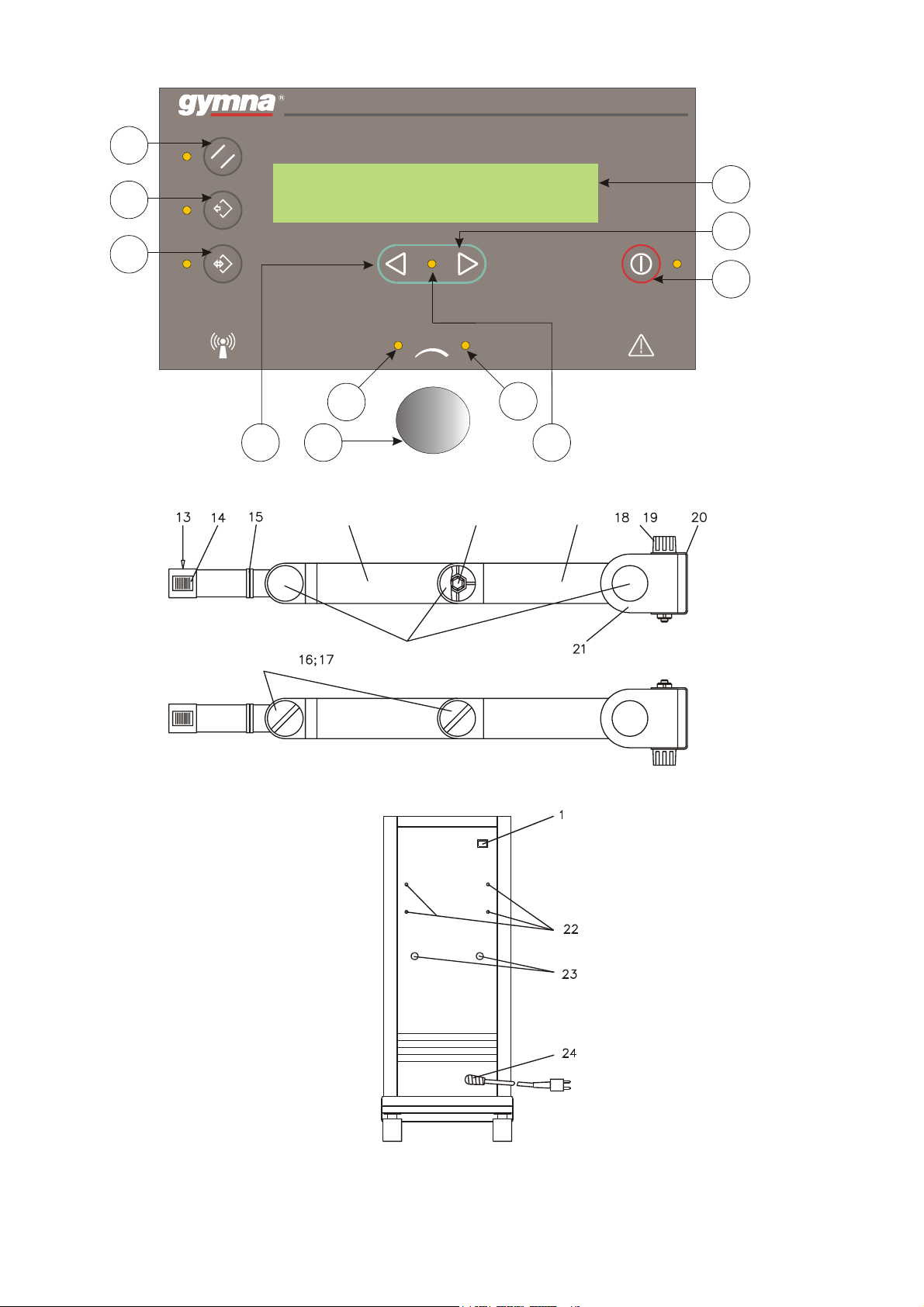
On the following page of this manual, you can find a drawing of the appliance. The
numbers mentioned below correspond to the numbers on the drawing.
1.2 Operation elements and symbols
1. Mains switch
2. Start/stop key
3. Standard mode key ‘Standard’
4. Free mode key ‘Free mode’
5. Indication mode key ‘Indication’
6. ‘Select <’ key
7. ‘Set/power’ turning knob
8. LED ‘set’, setting parameters active
9. LED ‘power’, setting power active
10. ‘Select >’ key
11. LED ‘Select active’
12. Display
13. Cable electrode fixing point
14. Adjustment regulator to fix the electrodes
15. Hinge
16/17. Locking/Fixing knob
12 THERMO 500 – User manual – version 2.1- 01/2002

18. Bottom part of the electrode arm
19. Locking/Fixing knob to turn loose/ fix the vertical movement of the arm
20. Fastening bracket
21. Bottom rotation hinge of the arm
22. Screws to fix the electrode arm
23. Contact points for electrode cable
24. Mains connection / Fuses
Please read the instruction manual first.
Not ionized radiation
THERMO 500 – User manual – version 2.1 - 01/2002 13
3
ce
5
4
SHORTWAVE THERAPY UNIT
THERMO 500
12
10
2
6
locking / fixing knob
Electrode arm
8
7
Middle part
of the arm
SET
Hexagonal screw
Cover
POWER
9
11
Bottom part
of the arm
Back side of the devi
14 THERMO 500 – User manual – version 2.1- 01/2002

2 IN GENERAL
2.1 Use of high-frequency heat therapy
The Thermo 500 is a high-frequency electrotherapy appliance, functioning on the set
frequency of 27,12 MHz (wavelength 11m). It enables using high-frequency heat
therapy in the coil-field, as well with one channel as with two channels. The
appliance is operated in the pulse mode, that is why it is suitable for all thermal and
a-thermal applications. The use of high-frequency energy for heat therapy offers the
advantage of a larger infiltration depth, compared to simpler procedures such as
compresses, baths, infrared light, thermal pillows and microwaves.
Endogenous heat causes a number of physiological processes affecting muscles,
thews and other interstitial tissue structures in a paroxysm removing manner, it
increases the cellular metabolism, the enzyme quickness of reaction and a continuous
blood circulation in the treated part.
With the possibility to apply the high-frequency energy in short and high energy
pulses (pulsed working) the depth working, in particular the increasing effect on the
blood circulation, can be raised further while a heat stimulus can hardly be felt on the
heat-sensitive skin.
The application scope of high-frequency heat therapy is very extensive. Into
prominence there are all rheumatic disorders and pains of muscles and joints,
inflammation diseases of the respiratory organs, the kidneys and urinary passages
and all diseases caused by a bad blood circulation.
2.2 The appliance
The Thermo 500 is an easily rolling device on large swivel castors. By means of the
break on the two rear castors you can prevent it from rolling when it is not desirable.
On the left of the appliance the mains switch (1) is installed. Setting the power is
done via the turning knob (7).
2.3 Electrode arms
At the reverse of the appliance, amongst others, the screw holes are situated to fix the
electrode arm(s) (22) and the connection contacts (23) for the cable of the coil-field
electrode(s), which are called “Thermoplodes” for the Thermo 500. The electrode
arms are assembled at the reverse of the appliance by means of the brackets (20).
Through its stable construction and five hinges, the electrode arm will be able to fix
the Thermoplodes steadily in all kinds of treatment positions. Except for the
horizontal turn of the arm and the hinge (15) in the Thermoplode fixing point (13)
the user can modify all the hinges according to specific needs. The fixing knob (19)
of the bottom rotation hinge (21) makes it possible to secure the entire electrode arm
with the arm maximally extended and with different electrode weights.
THERMO 500 – User manual – version 2.1 - 01/2002 15

After turning the locking knobs loose by means of the other main hinges (16) and
(17) length and height variations can be applied in a mutually combined action.
Herein the electrode arm needs to be supported at the upper hinges (15) and (16).
2.4 Electrodes
The Thermo 500 is an appliance for one- or two-channel short-wave therapy.
Standard, 1 coil-field electrode with a 14 cm diameter is supplied with the appliance
(see also chapter 10 SURVEY OF THE ACCESSORIES).
The Thermoplodes and cables are especially adapted to the Thermo 500. So please
do not use other cables and electrodes for safety reasons.
2.5 Contact-control in case the distance between the
Thermoplodes and the skin is too big
When the contact with a Thermoplode becomes insufficient as a result of a
movement of the patient, (if the electrode is not placed on the skin) ) the display
shows this. Nevertheless, the treatment time continues. In case the situation is still
the same after 10 seconds, there is an additional whistle alarm and the treatment time
stops. After an adjustment of the contact, the treatment will automatically be
continued.
Caution!
1. For an optimum effect, the Thermoplode has to be placed directly on the area
to be treated.
2. To set the power please pay attention to the instructions for use of the
Thermo 500 and the parameter proposal of the indications. In particular you
should pay attention in case of Thermal treatments. The feeling of warmth
will have a delaying effect on structures which are deeper.
3. You should adjust the Thermoplode to the size of the area to be treated. The
surface to be treated should correspond to the surface area of the electrodes.
If the contact is bad or in bony areas the message “improve position
Thermoplode” appears.
4. If there is no contact and the power is set to high, the Thermoplode will heat
up internally, in particular near to the cable connection.
5. Defects of the Thermoplode due to incorrect use are not covered by the
warranty.
When cleaning and disinfecting the appliance, prevent any liquid from entering the
appliance or parts of the accessories. Contact points, which have become wet, need
to be dried thoroughly before further use.
16 THERMO 500 – User manual – version 2.1- 01/2002

2.6 European Directive for Medical Devices 93/42/EEC -
Medical Devices Directive (MDD)
The Thermo 500 meets the MDD- requirements. It complies with the general
demands of labour safety by applying the valid technical standards and observing the
conditions in technical files.
According to the MDD this electro-medical device can only be used by persons who
can guarantee a professional application based on their education or their knowledge
and practical experience and who have been trained in order to use the appliance
correctly taking into account the instructions of this manual.
As manufacturer we can only be responsible and liable for the technical safety
characteristics of the appliance, when the Thermo 500 is used in accordance with the
instructions of the manual. Repairs, also opening the appliance, can only be executed
by us or by customer service partners authorised by us.
For the sake of the patients’ and users’ safety we recommend an annual safety test.
We have already experienced that most of the assumed malfunctions can often be
linked to mistakes and faults in using the appliance. So please check on the operation
of the appliance before calling the customer service.
Whoever using the appliance, should check on the operation and the condition
thereof. Regular check-ups of all the cables and wires on isolation defects are
essential.
Caution!
The appliance arouses high-frequency electric and magnetic fields coming right
through walls, ceilings and floors. It is inevitable that part of these fields occur near
the appliance.
Electronic devices in the vicinity of the Thermo 500 can be affected. The
disturbance strongly depends on the distance between the devices. Please notice to
place the appliance at a distance of at least 5 metres from surrounding electronic
(interference-sensitive) equipment and pay attention not to point the Thermoplodes
in the direction of other electronic devices such as electro-stimulation equipment and
other electronic apparatus. This problem can be solved completely when the shortwave appliance is put in a protected area, meaning a Faraday cage (a Faraday cage
does not allow electromagnetic fields).
THERMO 500 – User manual – version 2.1 - 01/2002 17

3 OPERATION
Caution!
The appliance cannot be used in an environment endangered with explosions. When
explosive narcotics are used simultaneously in the anaesthetic room, the danger of an
explosion cannot be excluded.
3.1 Check on delivery
Check whether the appliance has not been damaged during transport and whether the
accessories are intact and complete (see chapter 10 SURVEY OF THE
ACCESSORIES).
In the event of damage or defects, contact your supplier. Do not switch the appliance
on in case of serious damage. When the appliance is damaged after the first use, you
should have it checked by an authorised organisation.
3.2 Current connection
The appliance must be connected to a mains voltage of 230 V ± 10 % and 50/60 Hz.
There is a special edition for 115 V ± 10 % and 50/60 Hz. Mind the model plate on
the reverse of the appliance. Before connecting to the current network, you must
check the accordance with the model plate.
The connection can only happen by means of the current cable being part of the basic
equipment and a regulatory installed socket. For the fuse we recommend 10 A with
230 V.
3.3 Switching on
You can switch the appliance on by means of the mains switch (1) on the left-hand
side of the console. The name of the appliance and the software version are shown
for a while on the display. During an internal test of the appliance all the blinkers
(indicating lights) start to illuminate shortly and after a buzzer sound the appliance is
set in the standard mode (the standard mode LED lights up and the concerned
information is shown on the display).
18 THERMO 500 – User manual – version 2.1- 01/2002

T h e rm o 500
V e r s ion 11.xx x
The following settings are done via the console.
3.4 Functional test
The appliance is tested during production for electrical safety. Each time the
appliance is switched on, the microprocessor carries out a profound functional test to
assess afterwards whether the displays function correctly. If a fault is detected, you
cannot use the appliance and you must have it repaired.
3.5 Selection of language
The appliance offers various language options. When you keep the “ SELECT "
and “SELECT " - keys pressed while switching on, the Thermo 500 enters the
setting mode for the user’s language.
E NGLISH
The language can be selected by means of the turning knob: English, Nederlands,
Deutsch or Français.
By pressing the start/stop key the appliance is ready-for-use.
3.6 Sending / shipping (Transport)
In case the appliance needs to be sent/transported, we advise you to use the original
packaging.
THERMO 500 – User manual – version 2.1 - 01/2002 19

4 SELECTION OF THE SETTING MODE
4.1 Selection via the standard mode
When switched on the Thermo 500 will automatically start in the standard mode.
As the various parameters have already been pre-programmed, you can immediately
start the treatment in this mode. You only have to set the desired power and possibly
the treatment time.
Also after pressing the ”standard mode key” the Thermo 500 comes into
standard mode. The LED near the key lights up.
The parameter values depend on the connected and automatically traced
Thermoplode(s). The various situations are described hereinafter.
4.1.1 There is no Thermoplode connection
ST A N DARD
2 0 min
The programme cannot be started. After the start/stop key is pressed the
Thermo 500 alarm buzzer will sound.
Immediately after the Thermoplode is connected the concerned electrode symbol
appears on the display and the programme can be started.
4.1.2 There is one Thermoplode connection
A Thermoplode 140 is for example connected to the left channel, the START
window looks as follows:
ST A N DARD
7 0 . 0 W 2 0 min
In the START window you can see the connected Thermoplode, the average power
and the treatment time.
20 THERMO 500 – User manual – version 2.1- 01/2002

The parameters of the connected Thermoplode 140 are :
pulse time 400 µs
pulse frequency 875 Hz
average power 70 Watt
The parameters of a connected Thermoplode 80 are:
pulse time 400 µs
pulse frequency 500 Hz
average power 32 Watt
The parameters if a Thermoplode 80 and a Thermoplode 140 are connected
simultaneously are:
Thermoplode 80 Thermoplode 140
pulse time 400 µs pulse time 400 µs
pulse frequency 500 Hz pulse frequency 500 Hz
average power 32 Watt average power 40 Watt
To show these parameters, you press again the standard mode key calling in
the parameter window.
4.1.3 Two Thermoplodes 140 are connected
As well to the left as to the right channel a Thermoplode 140 is connected, the
START window looks as follows:
S T ANDARD
4 0 . 0 W 20min 40.0W
To show these parameters, you press again the standard mode key .
4 0 0 µ s 5 0 0 H z 4 0 0 µ s
2 0 0 W 20min 200W
The previously set treatment time is 20 minutes. This is the only parameter which
can be set now by means of the turning knob (the setting is also possible in the
START window by means of the standard mode). The parameter flashes the moment
the treatment time can be set.
The treatment can be started using the start/stop key
START window is shown again:
THERMO 500 – User manual – version 2.1 - 01/2002 21
. On the display the

S T A N D A R D
0 . 0 0 W 2 0 : 0 0 0 . 0 0 W
The start value of the average power is 0.00 W (and the peak power 0 W). The cursor
flashes when the power can be set. The average power of the left channel can be
increased by the turning knob. After starting the treatment, the treatment time
parameter counts back in steps of 1 second.
S T A N D A R D
4 0 . 0 W 1 9 : 5 0 0 . 0 0 W
Press the SELECT > key
average power of the right channel flashes and can now be increased by means of the
turning knob.
to select the right-hand channel. The indication of the
S T A N D A R D
4 0 . 0 W 1 9 : 4 0 4 0 . 0 W
Press the standard mode key to display the parameters. The parameter settings
appear on the display. This window/screen displays the set peak power value.
4 0 0 µ s 5 0 0 H z 4 0 0 µ s
2 0 0 W 1 9 : 4 0 2 0 0 W
At the end of the treatment time, you can hear a buzzing sound of about 10 seconds
and the position of before the start is recovered, meaning set back to the initial value;
the power is automatically set back to 0 W.
Treatment can also be stopped before the end of the treatment time by pressing the
start/stop key .
22 THERMO 500 – User manual – version 2.1- 01/2002

4.1.4 Two different Thermoplodes are connected
A Thermoplode 140 has been connected to the left-hand channel and a Thermoplode
80 to the right-hand channel. The START display looks like this:
S T ANDARD
4 0 . 0 W 20min 32.0W
To display the parameters, press the standard mode key again .
If a Thermoplode 80 is connected you should bear in mind that the average power
may not exceed 32 Watt. The Thermoplode 140, which is connected to the other
channel, then has a maximum average power of 40 Watt.
4 0 0 µ s 5 0 0 H z 4 0 0 µ s
2 0 0 W 20min 160W
The preset treatment time is 20 minutes. This parameter is the only one, which can be
set at this time with the turning knob (it can also be set in the START window of the
standard mode). The parameter flashes to indicate that the treatment time can be set.
Treatment can be started with the aid of the start/stop key . The START
window is again shown on the display :
S T ANDARD
0 . 0 0 W 20 :00 0. 00W
The starting value of the average power is 0.00 W (and the peak power 0 W). The
cursor flashes if the power can be set. The average power of the left-hand channel
can be increased with the turning knob. When treatment starts the treatment time will
count down in steps of 1 second.
S T ANDARD
4 0 . 0 W 19:50 0.00W
Press theSELECT >key to select the right-hand channel. The indication of the
average power of the right-hand channel flashes and can at this time be set with the
aid of the turning knob.
THERMO 500 – User manual – version 2.1 - 01/2002 23

S T A N D A R D
4 0 . 0 W 1 9 : 4 0 3 2 . 0 W
Press the standard mode key to display the parameters. The parameter settings
will appear on the display. The peak power set is shown in this screen.
4 0 0 µ s 5 0 0 H z 4 0 0 µ s
2 0 0 W
When you press the start/stop key , the treatment starts. At the end of the
treatment time, you can hear a buzzing sound of about 10 seconds and the position of
before the start is recovered, meaning set back to the initial value; the power is
automatically set back to 0 W
1 9 : 4 0 1 6 0 W
24 THERMO 500 – User manual – version 2.1- 01/2002

4.2 Selection via the indication list
The Thermo 500 disposes of a very extensive list of pre-programmed indications
with advice on the treatment parameters. In this way you can define your setting
quickly and simply, as well for well-known as for unknown pathologies. By means
of the centrally placed turning knob you can easily page the indication menu and
make your choice. The indication menu is drawn up in a way that takes into account
the current situation of the disorder. In the indication mode only the parameters
treatment time and average power can be set (up to the maximum peak power).
Caution!
For indications, the Thermo 500 automatically detects the type of Thermoplode that
is being connected. You can choose which type of Thermoplode you wish and to
which channel you want to connect the Thermoplode.
If you opt for a indication which has a higher average power than 32 Watt and you
have connected a Thermoplode 80, the Thermo 500 will automatically reduce the
average power to 32 Watt. This will reduce the peak power.
In that case a flashing Thermoplode 140/80 symbol will indicate that you have
connected the Thermoplode 80 (see chapter 5).
By pressing the indication mode key the Thermo 500 comes in indication
mode. The LED of the indication key lights up. The last used indication appears on
the display; after switching on the appliance, you always see the first indication of
the list. The list is arranged in alphabetical order.
C L A U D I C A T. I N T.
6 . 0 0 W
The appliance contains 38 indications (available in 4 languages). By means of the
turning knob you can page the indication list.
22min
A R T H E R I T I S
2 . 4 7 W
16min
THERMO 500 – User manual – version 2.1 - 01/2002 25

To see the parameters you have to press, from the START window illustrated above,
the indication mode key again. The parameter settings appear on the display:
2 0 0 µ s 6 5 H z
1 9 0 W 1 6 min
To return to the START window, you press the indication mode key again.
4.2.1 End of an indication programme
In the indication mode only the parameters treatment time and average power can be
set. After you have selected the indication, you will see the START window with the
advised parameters on the screen (the advised average power, in the example below
2.47 W, is the maximum value which you can set after pressing the start/stop key).
Press the SELECT > key to adapt the treatment time. The value flashes; by
means of the turning knob you can change the treatment time. (this can also be done
in the parameter window):
A R T H E R I T I S
2 . 4 7 W 1 2 min
By pressing the start/stop key , the treatment is started at the initial value of 0 W
of the average power.
A R T H E R I T I S
0 . 0 0 W 1 2 :00
By means of the turning knob the average power of the left channel can be raised to
the maximum average power of the displayed programme. The time indication
counts back in steps of 1 second.
A R T H E R I T I S
2 . 2 0 W 1 1 :50
When the electrode on the right-hand side is also connected, you can raise the
average power of the right channel by pressing theSELECT >key to the
maximum peak power of the displayed programme.
26 THERMO 500 – User manual – version 2.1- 01/2002

If you wish to see more information on the parameters, you have to press the
indication mode key . Subsequently the parameter settings appear on the
display. The average power can also be set in this window.
At the end of the treatment the treatment is terminated and the parameters are set
back to the initial values of the programme. At the end of the treatment time you will
also hear a buzzing sound of about 10 seconds. When you press the button
during treatment the power will go to “0” and the treatment time will give the time
when stopped in minutes
THERMO 500 – User manual – version 2.1 - 01/2002 27

4.3 Selection via the free mode
When you press the free mode key the Thermo 500 passes to free mode. On
the display “FREE DESIGN” appears and the LED near the key lights up. The free
mode contains 50 programme places, which can be freely programmed and saved, as
you wish. Only the first programme is a FREE DESIGN programme, which cannot
be saved.
The Thermo 500 automatically traces which Thermoplode is connected.
F R EE D ESIGN
2 0 min
By means of the turning knob you can page the programmes. The pre-programmed
names of the programmes are FREE 01 to FREE 49.
In the following example the Thermoplode 140 is connected to the left channel in
the free mode FREE 03. The previously set treatment time is 20 minutes.
FR E E 03
0 . 0 0 W 2 0 min
When you wish to see the parameters of this programme, you have to press the free
mode key again. Subsequently the parameter settings appear on the display.
The following parameter values are standard pre-set for all programmes.
Pulse time = 65 µs
Pulse frequency = 25 Hz
Peak power = 10 W
Treatment time = 20 minutes
6 5 µ s 2 5 H z 6 5 µ s
1 0 W 2 0 m i n 1 0 W
Parameters changed by you are automatically saved, even when the treatment has not
been started yet by means of the start/stop key .
28 THERMO 500 – User manual – version 2.1- 01/2002

If you change parameters after pressing the start/stop key and after starting the
treatment, these changes (parameters adapted during the treatment) are not saved.
After the treatment time or after stopping the treatment by pressing the start/stop key
the initial values appear again.
4.3.1 Characteristics of the cursor
You can change the position of the cursor on the display (the flashing character
which can be set by the turning knob), by pressing the SELECT or SELECT
key. Whenever a field is empty, an underlining flashes. By pressing SELECT the
fields are addressed in the following order.
4.3.2 Creation of a new programme
Overwriting a free programme or a previously saved programme creates new
programmes.
Basic principle of programming:
• Select the parameter to be set by pressing SELECT or SELECT
• Set the desired value of the selected parameter (flashing now) by means of the
turning knob
• Press SELECT or SELECT to pick out the following parameter
Caution!
When a parameter is changed, it is saved automatically. Pay attention not to
overwrite an existing programme unintentionally.
From the moment a programme can be started (this is when all relevant parameters
of at least one channel are set correctly), the LED key next to the start/stop key
lights up.
4.3.2.1 Programming sequence in free mode
Step 1
The first programme entered by the Thermo 500 after pressing the free mode key
is the “Free Design” programme. It is a standard programme which can be
changed and executed, but which is never saved after turning off the device.
THERMO 500 – User manual – version 2.1 - 01/2002 29

Use the turning knob to select a free programme position or a previously saved
programme. The free programmes are numbered from 01 to 49.
Caution!
In Free mode, indication and standard mode the Thermo 500 automatically detects
the type of Thermoplode being connected. You can choose which type of
Thermoplode you wish and to which channel you want to connect the Thermoplode.
If you opt for the free mode, which has a higher average power than 32 Watt and you
connect a Thermoplode 80, the Thermo 500 will automatically reduce the average
power to 32 Watt. This will reduce the peak power. In that case a flashing
Thermoplode 140/80 symbol indicates that you have connected the Thermoplode 80.
The average power of the Thermoplode 80 cannot be set higher than 32 Watt. The
Thermo 500 will always check this. If, for example, you set the frequency higher, so
that the average power of 32 Watt is exceeded, the peak power will automatically be
reduced.
The formula that is used to calculate this is:
Frequency x pulse time x peak power ≤ 32 Watt
Example:
4 0 0 µ s 4 0 0 H z 6 5 µ s
2 0 0 W 2 0min 10W
According to the formula the average power is precisely 32 Watt.
The pulse frequency is then increased to 500 Hz and the peak power is automatically
adjusted to 160 Watt so that the average power remains 32 Watt.
4 0 0 µ s 5 0 0 H z 6 5 µ s
1 6 0 W 2 0min 10W
Caution
A parameter is saved automatically when changed.
Pay attention not to overwrite an existing programme unintentionally.
The Thermo 500 automatically detects the presence of an Thermoplode and its
characteristics.
30 THERMO 500 – User manual – version 2.1- 01/2002

Step 2: Programme name
The name of the standard programme is “FREE N”, N stands for the number of the
following free memory place . You can overwrite or keep this name. If you want to
keep the name, push the SELECT > key till you reach the following parameter,
without changing the letters by means of the turning knob.
To overwrite the name, select the letters to be changed, by pressing SELECT and
change them by means of the turning knob (blank, A...Z, 0...9, _ , - , and so on.):
_ F R EE 01
0 . 0 0 W
20min
P_ F R EE 01
0 . 0 0 W
20min
PR _ F R EE 01
0 . 0 0 W
And so on till the desired name, for example “PROGRAM 4” is ready.
Step 3
Push the SELECT > key to select the parameter of the treatment time. The preselection is 20 minutes.
20min
P R O G R A M 4 _
0 . 0 0 W 20min
The treatment time parameter can be set in steps of 1 minute till a maximum value of
60 minutes.
In the START window no other parameters can be set. In this way the programme
place is again selected by pressing SELECT again.
Step 4
Push the free mode key to display the parameter window. When a
Thermoplode of the right channel has also been connected, these parameters are also
displayed on the screen.
First the pulse time of the left Thermoplode is selected.
Attention! All the Free mode programs have already the minimum parameter setting.
THERMO 500 – User manual – version 2.1 - 01/2002 31

6 5 µ s 2 5 H z 6 5 µ s
1 0 W 2 0 m i n 1 0 W
The pulse time of the left channel can be set from 65 µs to 400 µs in steps of 5 µs.
Step 5
Push the SELECT > key
to select the parameter pulse frequency.
6 5 µ s 2 5 H z 6 5 µ s
1 0 W 2 0 m i n 1 0 W
The pulse frequency can be set
• from 25 Hz to 875 Hz in one channel therapy and in connecting the
Thermoplode 140 or
• from 25 Hz to 500 Hz in two channel therapy and in connecting two
Thermoplodes 140
• from 25 Hz to 875 Hz in connecting a Thermoplode 80
• from 25 Hz to 500 Hz in connecting two Thermoplodes 80
• from 25 Hz to 500 Hz in connecting a Thermoplode 140 and a Thermoplode 80.
Setting in steps of 5 Hz. This parameter pulse frequency applies to both
channels!
Step 6
Push SELECT 2x to select the peak power parameter of the left channel.
6 5 µ s 2 5 H z 6 5 µ s
1 0 W 2 0 m i n 1 0 W
By means of the turning knob you can set the peak power from 10 W to 200 W in
steps of 5 W. As long as the start/stop LED is off, you cannot start the programme. In
any case the peak power has to be set in order to have the start/stop LED lightened
up.
Caution!
If a Thermoplode 80 is connected, the peak power to be set will be limited if the
average power of 32 Watt is exceeded. (This occurs for high parameters for the pulse
frequency and pulse time.)
32 THERMO 500 – User manual – version 2.1- 01/2002

Step 7
Push the SELECT > key possibly to select the treatment time parameter, which in
this window can also be set in a previously started programme. The time parameter
can be set in steps of 1 minute, till 60 minutes maximally.
All the parameters set in stand-by mode are automatically saved.
Programming illogical parameters is impossible. As long as the start/stop LED is off,
you cannot start the programme.
Step 8
The programme can be started by the start/stop key . The START window is
shown on the display. After the start the average power first equals 0.00 W.
P R O G R A M 4
0 . 0 0 W 20:00
In practice the treatment only starts by turning on the power knob. Only at that
moment the treatment time starts to run. The turning knob is automatically active for
the left channel.
When the running (active) programme disposes of a right channel function and in
case the right channel Thermoplode is connected, the average power of the right
channel can be selected by pressing the SELECT > key . Following the selection
of the average power parameter of the right channel, you can set it by means of the
turning knob.
Step 9
When you want to change a parameter during the treatment, you have to push the
free mode key
parameter pulse time of the left channel is selected:
again to display the parameter window. To illustrate this, the
4 0 0 µ s 4 0 0 H z 6 5 µ s
2 0 0 W 19:30 10W
The parameter can be set by means of the turning knob. The setting directly affects
the average power and the display of Prms in the START window.
Push the SELECT > key when you want to set the next parameter.
During the treatment (meaning with an increased power) the changed/modified
parameters are not saved !
THERMO 500 – User manual – version 2.1 - 01/2002 33

At any time the START window can be called by pressing the free mode key .
At the end of the treatment time and by pressing the start/stop key the treatment
is terminated and the parameters are set back to the initial value of the programme.
At the end of the treatment time you will also hear a buzzing sound of about 10
seconds.
4.3.3 Execution of the programme
The desired programme is called by means of the turning knob.
P R O G R A M 1 6
3 2 . 0 W 1 0 : 0 0 1 6 . 0 W
Push the start/stop key to start the programme. You can continue working as
described in step 10 of paragraph 4.3.2.1.
34 THERMO 500 – User manual – version 2.1- 01/2002

5 CONTROL OF THE ELECTRODE
CONNECTION
The Thermo 500 disposes of an on-line control of the connection and type of
Thermoplode.
In Free mode, indication and standard mode the Thermo 500 automatically detects
the type of Thermoplode being connected. You can choose which type of
Thermoplode you wish and to which channel you want to connect the Thermoplode.
If you opt for the free mode or indication which has a higher average power than 32
Watt and you connect a Thermoplode 80, the Thermo 500 will automatically reduce
the average power to 32 Watt. This will reduce the peak power and/or pulse
frequency.
A flashing Thermoplode 140/80 symbol indicates that you have connected the
Thermoplode 80.
The average power of the Thermoplode 80 cannot be set higher than 32 Watt. The
Thermo 500 will always check this. If, for example, you set the frequency higher
(max. 500 Hz), the peak power will automatically be reduced.
The formula that is used to calculate this is:
Frequency x pulse time x peak power ≤ 32 Watt
Example :
4 0 0 µ s 4 0 0 H z 6 5 µ s
2 0 0 W 20min 10W
If the pulse frequency is then increased to 500 Hz then the peak power will
automatically be adjusted to 160 Watt
4 0 0 µ s 5 0 0 H z 6 5 µ s
1 6 0 W 20min 10W
THERMO 500 – User manual – version 2.1 - 01/2002 35

6 TREATMENT
6.1 Preparing the patients
To achieve an optimal way of treatment, the patients and the body part to be treated
should best be relaxed completely. Lying or sitting comfortably is essential.
Patients cannot be treated in metal chairs or couches. For safety reasons it is
recommended that hearing-aids, watches, rings, necklaces, bracelets and other metal
objects be removed before the treatment. The same principle applies to people who
are in the vicinity of the appliance or near the Thermoplodes and cables, for example
the medical staff.
The body parts concerned are treated naked. Clothes made of synthetic fabrics have
to be removed because of the low absorbing capacity. Moist skin, for example in
skin creases, can cause local overheating. To avoid this and from a hygienic point of
view, it is recommended to put a dry layer of cellulose or a thin terry cloth between
the Thermoplode and the treated body part. The patient cannot touch metal objects
during the treatment, neither the appliance itself, nor the metal parts of connections.
6.2 Thermal effect of the coil-field method
The coil-field electrodes cause Foucault currents as a result of their high-frequency
magnetic field, converted into heat in the tissue. The currents are even higher, when
the electric conduction of the tissue is higher (tissue with a good blood circulation,
for example muscular tissue and internal organs). To reach the deeper located tissue,
the coil-field electrodes of the Thermo 500 have an electrostatic fence reducing the
electric field of the coil-field electrodes by which the coil-field electrodes which
impede the thermal effect on the epidermis tissue.
6.3 Indications
Specific indications for pulsing short-wave therapy are:
Post-traumatic lesions, such as:
• distortion
• contusion
• rupture
• fracture
• haematoma
36 THERMO 500 – User manual – version 2.1- 01/2002

Post-operative lesions
Inflammation, such as :
• arthritis (in a non-active stage)
• bursitis, possibly with calcification
• sinusitis
• tendinitis
• wound healing
Degenerative lesions, such as :
• arthrosis
• rheumatoid arthritis
Lesions of the peripheral nerves, such as :
• pareses
• neuritoids, neuralgias
• herpes zoster
• neuropathy
6.3.1 Contra-indications
General contra-indications:
• high fever
• serious cardiac disorders
• psychological problems (aversion of the patient, fear)
• general : cancer, malignant tumours (metastasis)
• general : tuberculosis.
• in principle : reduced heat sensation in the affected area
Implanted metals
It is not allowed to treat patients with pacemakers with high-frequency heat therapy.
Body parts with metal parts (pins, shell shrapnel or similar things) cannot be treated.
Pregnant women, threatened organs
The treatment of pregnant women in the abdomen is not advised.
Other contra-indications are :
. growing zones of the bone/os
. malignant tumours
. tuberculosis
. arterial haemorrhage disorders of stage III and IV
. varicose veins
. general tendency to bleed
In organs with a minor vasculature and blood circulation (eyes, testicles)
administer the dose carefully!
Also the thermal dose with patients with a disordered heat sensation must be
avoided.
THERMO 500 – User manual – version 2.1 - 01/2002 37

7 MALFUNCTIONS, GUARANTEE,
RELIABILITY, CUSTOMER CARE
7.1 Malfunctions
The Thermo 500 independently tests itself. If functions do not work anymore, so
that the parameters are situated outside the allowed deviations, the mention “Call
Customer Service” appears on the display. This mention can also appear on the base
of other (external) factors. After switching the appliance on and off, it is ready for
use again.
Faults, which are caused by a wrong use of the appliance, are clearly indicated on
the display.
7.2 Guarantee and reliability
7.2.1 Terms of guarantee
The guarantee does not apply to repairs of faults or defects originated by a negligent
use of the appliance, by a wrong interpretation of the faults or a non-correspondence
to the instructions of this manual, by not observing the instruction manual, or by
accidents, caused by maintenance or repair by people not authorised by the company
GymnaUniphy.
7.2.2 Liability of the manufacturer
After a period of 10 years following the first operation of the appliance (or its
accessories) the manufacturer cannot be held liable for defects to the appliance, to
its accessories, or for possible ensuing damage.
Neither can the manufacturer be held liable for ensuing injury or harm to therapists,
patients or the used accommodation after for example a wrong diagnosis, nonprofessional utilisation of the appliance or its accessories, wrong interpretation or
non-observance of the instruction manual, after a bad maintenance of the appliance
or in case a maintenance or repair have been carried out by persons not authorised
by the manufacturer.
The manufacturer, nor the supplier, can be held responsible by any means for the
transmission of infections through catheters/probes or electrodes.
38 THERMO 500 – User manual – version 2.1- 01/2002

7.3 Customer care
Your supplier is only responsible for effective operation of the appliance when:
• Repairs are carried out by authorised persons;
• the electrical installations in the area involved comply with the applicable legal
guidelines;
• all repairs, modifications, extensions or settings are carried out by authorised
persons according to the guidelines of this instruction manual;
• the appliance is used for the purpose for which it has been designed;
• maintenance has been carried out regularly and in the described manner;
• the legal guidelines for using the appliance have been observed.
Apart from the fuses, no components in the appliance can be replaced by the user. In
the event of improper use or lack of maintenance according to the guidelines,
GymnaUniphy and its representatives are released of all liability of any ensuing
damage, injury, breakdowns and malfunctions.
Your supplier takes care of all the interventions as to customer service and guarantee.
Your supplier’s terms and conditions of delivery are applicable.
The guarantee lapses if the appliance is not used in accordance with the instructions
above. The expected lifespan of the appliance is 10 years.
THERMO 500 – User manual – version 2.1 - 01/2002 39

8 MAINTENANCE AND CLEANING
For maintenance and cleaning to the Thermo 500 first switch off the appliance and
remove the plug from the wall socket.
8.1 Cleaning and disinfection
For the normal, daily maintenance of the appliance, the appliance and its accessories
need not to be opened. If necessary the outside can be cleaned by means of a dry or
slightly moistened cloth.
We strictly advise against the use of solvents, considering they can damage the used
materials. Persistent stains can be removed with a non-caustic soap substance.
Anyway prevent any liquid from entering the appliance or its accessories! All parts
must be dried carefully.
To clean and disinfect the appliance and its accessories (except for felt parts) we
advise disinfectants on sale everywhere, according to the instructions. For erasing
and sprinkling disinfection, only disinfectants with aldehyde, alcohol or quaternary
ammonia compounds can be used, for protective reasons, observing the guidelines of
the manufacturer regarding dilution and effect.
For users in Germany we only advise the use of disinfectants appearing on the latest
DGHM list (DGHM: Deutsche Gesellschaft für Hygiene und Mikrobiologie). This
list also mentions the substance basis of the disinfectants. Because of possible
damage to the materials, preparations on the base of halogen secreting compounds
cannot be used, nor strong organic acids, compounds giving off oxygen, solvents,
petrol and so on…
To guarantee the quality and safety, unauthorised persons cannot open the appliance
or its accessories by any means. Opening the appliance or its accessories (for
maintenance or repair) is preserved to qualified personnel authorised by the company
GymnaUniphy.
40 THERMO 500 – User manual – version 2.1- 01/2002

9 TECHNICAL SPECIFICATIONS
Current connection
230 V ± 10 %: 50/60 Hz
115 V ± 10 %; 50/60 Hz
Electric fuse/external
10 A at 230 V
16 A at 115 V
Fuses, externally accessible 6,3 AF at 230 V
6,3 AT at 115 V
Insulation class I, Type BF (with connected electrodes)
Safety degree IP 20
Power absorption max.
Power in stand-by
Frequency
Peak power P
pulse
Average power/power Prms
- Per channel, Thermoplode 140 in two channel operation
- 1 channel, Thermoplode 140
- Per channel, Thermoplode 80 in two channel operation
- Thermoplode 80 and Thermoplode 140 in
two-channel operation
Approximately 450 VA
Approximately 100 VA
27,12 MHz ± 0,6 %
200 W at 50 Ohm
Max. 40 W
Max. 70 W
Max. 32 W
Thermoplode 80 : Max. 32 W
Thermoplode 140 : Max. 40 W
Pulse time
Pulse frequency
65 – 400 µs
25 - 500 Hz in two channel operation
25 - 875 Hz in one channel operation
Treatment time 0 – 60 minutes
Dimensions (w x d x h) 371 mm x 356 mm x 930 mm
Weight Approximately 43 kg (excl. Thermoplode)
Exits 2 coaxial exits (protected) for Thermoplodes
Standards EN 60 601-1: 1990+A1+A2+A13
EN 60 601-1-2: 1993
EN 60 601-2-3: 1993+A1
MPG-class
EC sign
IIa
complying with the directive
MDD: 93/42/EEC
THERMO 500 – User manual – version 2.1 - 01/2002 41

10 SURVEY OF THE ACCESSORIES
10.1 Standard accessories
Number Description
1 instruction manual Thermo 500
1 coil-field electrode “Thermoplode” 140, 14 cm diameter, excl. cable
1 electrode cable for the “Thermoplode”
1 electrode arm with a 10 mm open-end wrench to set the arm
1 Swiss adaptor
10.2 Optional accessories
Description
• Coil-field electrode “Thermoplode 80”, diameter 8 cm, excl. cable
• Electrode cable for the “Thermoplode”
• Coil-field electrode “Thermoplode 140” diameter 14 cm, excl. cable
• Electrode arm with a 10 mm open-end wrench to set the arm
We are always concerned to keep our appliances technically up-to-date. Therefore
we entitle ourselves to carry out modifications or adaptations whenever necessary.
42 THERMO 500 – User manual – version 2.1- 01/2002

NEDERLANDS
INLEIDING
Gefeliciteerd!
U heeft gekozen voor de Thermo 500, een kortegolftherapie-apparaat met hoge
prestaties, een aantrekkelijke vormgeving, gebruiksvriendelijk en van duurzame
kwaliteit.
In fysiotherapiepraktijken, bij de arts en in ziekenhuizen bewees de Thermo 500 zijn
deugdelijkheid.
Bij de ontwikkeling ervan hechtten wij veel belang aan de hoge
betrouwbaarheidsgraad, veiligheid, eenvoudige bediening en een lange levensduur.
Leest u voor een juist gebruik van de Thermo 500 eerst de volgende
gebruiksaanwijzing.
Wij wensen u en uw patiënten veel succes bij de behandeling met de Thermo 500.
GymnaUniphy NV
43 THERMO 500 – Gebruikershandleiding – versie 2.1 – 01/2002

11 BEDIENINGSELEMENTEN EN
SYMBOLEN
11.1 Inleiding
Zie voor de tekening met nummerverwijzingen de volgende pagina in deze
handleiding.
11.2 Bedieningselementen en symbolen
1. netschakelaar
2. start/stop toets
3. standaard mode toets ‘Standard’
4. vrije -mode toets ‘Free mode’
5. indicatie mode toets ‘Indication’
6. toets “SELECT <”
7. draaiknop “set/power”
8. LED ‘set’; instellen parameters , actief
9. LED ‘power’; instellen vermogen actief
10. toets “SELECT >”
11. LED ‘Select actief’
12. display
13. bevestigingspunt voor de elektrode
14. schuifregelaar voor de bevestiging van de elektrode
15. scharnier
16./17. vergrendelknop
THERMO 500 – Gebruikershandleiding – versie 2.1 – 01/2002 44

18. onderste gedeelte elektrode-arm
19. vergrendelknop voor losdraaien/fixeren van de verticale beweging van de arm
20. bevestigingsbeugel
21. onderste draaipunt van de arm
22. schroeven ter bevestiging van de elektrode-arm
23. aansluitpunt elektrode-kabel
24. netaansluiting / zekeringen
leest u eerst de gebruiksaanwijzing
Niet ioniserende straling
45 THERMO 500 – Gebruikershandleiding – versie 2.1 – 01/2002

3
5
4
SHORTWAVE THERAPY UNIT
THERMO 500
12
10
2
Vergrendelknop
Elektrode arm
6
Middelste deel
van de arm
7
8
SET
Deksel
POWER
Zeskantbout
9
11
Onderste deel
van de arm
Achterzijde van het apparaat
THERMO 500 – Gebruikershandleiding – versie 2.1 – 01/2002 46

12 ALGEMEEN
12.1 Gebruik van de hoogfrequente elektrotherapie
De Thermo 500 is een hoogfrequent elektrotherapietoestel, dat functioneert op de
vastgestelde frequentie van 27,12 MHz (golflengte 11 m). Het maakt het gebruik
van hoogfrequente warmtetherapie in het spoelveld mogelijk, zowel met één- als met
twee kanalen. Het toestel werkt in de gepulseerde mode en is geschikt voor alle
thermische én a-thermische toepassingen.
Het gebruik van hoogfrequente energie voor de warmtetherapie biedt in vergelijking
met eenvoudigere procédés als kompressen, baden, infrarood-licht, warmtekussens
en microgolven het voordeel van de grotere infiltratiediepte.
De endogene warmte veroorzaakt een aantal fysiologische processen die
bijvoorbeeld spieren, pezen en andere bindweefselstructuren krampopheffend
beïnvloedt, de celstofwisseling en de enzymreactiesnelheid verhoogt en de
doorbloeding in het behandelde gebied verhoogt.
Met de mogelijkheid de hoogfrequente energie in korte en hoge energiestoten aan te
wenden (gepulseerde werking) kan de dieptewerking, in het bijzonder de
doorbloedingsverhogende werking, verder verhoogd worden terwijl op de
warmtegevoelige huid amper een warmteprikkel voelbaar is.
Het toepassingsgebied voor de hoogfrequente warmtetherapie is zeer omvangrijk. Op
de voorgrond staan alle reumatische aandoeningen van gewrichten en spieren,
ontstekingsziekten van de ademhalingsorganen, nieren en urinewegen en alle ziekten
waar een gebrekkige doorbloeding aan de basis ligt.
12.2 Het toestel
De Thermo 500 is eenvoudig verrijdbaar door de grote wielen. Met behulp van de
rem op de twee achterwielen kan voorkomen worden dat het toestel verrijdt op
momenten dat dat niet gewenst is.
Aan de linkerkant van het toestel vindt u de netschakelaar (1). Het instellen van het
vermogen gebeurt met de draaiknop (7).
12.3 Elektrode-armen
Aan de achterkant van het toestel bevinden zich onder andere de schroefgaten voor
de bevestiging van de elektrode-arm(en) (22) en de bevestigingspunten (23) voor de
kabel van de spoelveldelektrode(n), bij de Thermo 500 worden deze ‘Thermoplode’
genoemd. De elektrode-armen worden met behulp van de beugels (20) aan de
rugzijde van het toestel gemonteerd.Met zijn stabiele constructie en vijf scharnieren
maakt de elektrode-arm het u mogelijk om in veel verschillende behandelingsposities
de Thermoploden stabiel te bevestigen. Behalve de horizontale zwenking van de arm
en de scharnier (15) bij het bevestigingspunt van de Thermoplode (13) kan de
gebruiker alle scharnieren aanpassen aan de specifieke wens. De fixeerknop (19)
voor het onderste draaipunt (21) zorgt ook bij het maximale uittrekken van de arm en
47 THERMO 500 – Gebruikershandleiding – versie 2.1 – 01/2002

bij verschillende elektrodegewichten voor het vastzetten van de gehele elektrodearm.
Na het losdraaien van de vergendelknoppen kunnen met de andere hoofdscharnieren
(16) en (17) in wederzijds samenspel lengte- en hoogtevariaties doorgevoerd worden.
Daarbij moet de elektrode-arm bij de bovenste scharnieren (15) en (16) ondersteund
worden.
12.4 Elektroden
De Thermo 500 is een apparaat voor één- of tweekanaals kortegolftherapie.
Standaard wordt 1 spoelveldelektrode met een doorsnede van 14 cm meegeleverd. zie
ook hoofdstuk 20: OVERZICHT VAN HET
De Thermoploden en kabels zijn speciaal voor de Thermo 500 ontworpen. Gebruik,
om veiligheidsredenen, nooit andere kabels en elektroden.
TOEBEHOREN.
12.5 Gedrag behandeltijd bij te grote afstand tussen de
Thermoploden en de huid
Wanneer door een beweging van de patiënt de verbinding met een Thermoplode
onvoldoende wordt (indien de elektrode niet op de huid is geplaatst), wordt dit op het
display gesignaleerd door middel van een melding. De behandeltijd loopt echter
door. Wanneer deze situatie na ongeveer 10 seconden nog bestaat, volgt een
bijkomend geluidssignaal en stopt de behandeltijd. Nadat u of de patiënt het contact
met de huid hersteld heeft, wordt de behandeling automatisch voortgezet.
Opgelet!
1. Voor een optimale werking moet de Thermoplode direct aan het te
behandelen gebied aangelegd worden.
2. Voor het instellen van het vermogen dient u te letten op de beschrijving van
het gebruik van de Thermo 500 en het parameter voorstel van de indicaties.
In het bijzonder dient u op te letten bij Thermische behandelingen. Het
warmtegevoel zal een vertragende werking hebben op dieper liggende
structuren.
3. U dient de Thermoplode aan te passen aan de grootte van het te behandelen
gebied. Het te behandelen oppervlak dient overeen te komen met het
oppervlak van de elektroden. Bij slecht contact of bij botachtige regio’s
verschijnt de melding “positie elektroden verbeteren”
4. Bij gebrek aan contact en een hoog vermogen zal de Thermoplode intern
warm worden, in het bijzonder bij de kabelaansluiting.
5. Defect van de Thermoplode door verkeerd gebruik valt niet onder de garantie
Bij reiniging en ontsmetting mag geen vloeistof in het toestel of in delen van het
toebehoren dringen. Vochtig geworden contactpunten moeten vóór verder gebruik
grondig worden gedroogd.
THERMO 500 – Gebruikershandleiding – versie 2.1 – 01/2002 48

12.6 EU-Richtlijn voor medische hulpmiddelen
93/42/EEG -Medical Devices Directive (MDD) -
De Thermo 500 voldoet aan de eisen die gesteld worden aan een MDD-klasse IIa
apparaat. Hij voldoet door toepassing van de geldende technische normen en regels
en door de naleving van de bepalingen in de technische dossiers aan de algemene
eisen van de arbeidsveiligheid.
Volgens de MDD mag dit elektro-medisch toestel alleen gebruikt worden door
personen die op basis van hun opleiding of hun kennis en praktische ervaring borg
staan voor een vakkundige gebruik, en die aan het toestel door middel van deze
gebruiksaanwijzing opgeleid werden voor een juist gebruik.
Als fabrikant kunnen wij ons slechts dan verantwoordelijk voelen voor de
veiligheidstechnische eigenschappen van het toestel, wanneer de Thermo 500 in
overeenstemming met de gebruiksaanwijzing wordt gebruikt.
Herstelwerkzaamheden, ook het openen van het toestel, mogen alleen uitgevoerd
worden door de fabrikant of door de fabrikant geautoriseerde service-monteurs.
In het belang van de veiligheid van patiënten en therapeuten bevelen wij een
jaarlijkse veiligheidstechnische controle aan.
Vermeende storingen zijn regelmatig terug te voeren op vergissingen en fouten bij
het gebruik. Verifieert u daarom de werking van het toestel alvorens u de hulp van
een service-afdeling inroept.
Wie het toestel gebruikt, moet zich op de hoogte stellen van het functioneren en de
goede toestand van het toestel. Regelmatige visuele controles van alle kabels en
leidingen op isolatiedefecten zijn daarbij onontbeerlijk.
Opgelet!
Het toestel wekt voor zijn werking hoogfrequente elektrische en magnetische velden
op die ook door wanden, zolderingen en vloeren dringen. Het is onvermijdelijk dat
een deel van deze velden optreden in de omgeving van het toestel. Elektronische
apparatuur die zich in de onmiddellijke nabijheid van de Thermo 500 bevindt kan
hierdoor gestoord worden. Deze storing is zeer sterk afhankelijk van de onderlinge
afstand tussen de apparaten. Let er bij de opstelling van het toestel dan ook op, dat
de afstand tot andere storingsgevoelige apparatuur zo mogelijk groter is dan 5 meter
en dat de Thermoploden zo mogelijk niet gericht worden op andere storingsgevoelige
apparatuur zoals bijvoorbeeld elektrostimulatie-apparatuur of andere elektronische
apparatuur. Dit probleem kan volledig opgelost worden wanneer het kortegolftoestel
in een afgeschermde ruimte, dat wil zeggen in een kooi van Faraday, wordt
ondergebracht (een kooi van Faraday laat geen elektromagnetische velden door).
49 THERMO 500 – Gebruikershandleiding – versie 2.1 – 01/2002

13 INGEBRUIKNAME
Opgelet!
Het toestel mag niet gebruikt worden in met een explosies bedreigde omgeving.
Wanneer in anesthesielokalen gelijktijdig met ontplofbare narcosemiddelen wordt
gewerkt, ontstaat explosiegevaar.
13.1 Ingangscontrole
Controleer of het toestel tijdens het transport niet beschadigd werd en of het
toebehoren intact en volledig is.
TOEBEHOREN.
Breng uw leverancier op de hoogte van eventuele schade of defecten. Schakel het
toestel niet in bij ernstige beschadiging. Wanneer het toestel na een eerste gebruik
beschadiging oploopt, moet u het door een bevoegde instelling laten controleren.
13.2 Stroomaansluiting
zie hoofdstuk 20 OVERZICHT VAN HET
Het toestel moet aangesloten worden aan een netspanning van 230 V ±10 % en 50/60
Hz. Er is een speciale uitvoering voor 115 V ± 10 % en 50/60 Hz. Let op het
typeplaatje op de rugzijde van het toestel.
Vóór aansluiting aan het stroomnet moet de overeenstemming met het typeplaatje
gecontroleerd worden.
De aansluiting mag alleen gebeuren met behulp van de tot de basisuitrusting
behorende vaste netkabel en een reglementair geïnstalleerd stopcontact. Voor de
zekering bevelen wij 10 A bij 230 V aan.
13.3 Inschakelen
Met de netschakelaar (1) aan de linker achterzijde van de Thermo 500 schakelt u het
toestel in. Een tijdlang worden toestelnaam en softwareversie op het display
weergegeven. Tijdens de interne test van het toestel lichten kortstondig alle
verklikkerlampjes op en na een signaaltoon bevindt het toestel zich in standaard
mode (de standaard mode-LED brandt en de betreffende vermelding verschijnt op
het display).
T he r m o 500
V e rs i o n 11.xx x
Alle volgende instellingen gebeuren via het bedieningspaneel.
THERMO 500 – Gebruikershandleiding – versie 2.1 – 01/2002 50

13.4 Werkingscontrole
Bij de fabricage van de Thermo 500 is de elektrische veiligheid van het toestel getest.
Bij het inschakelen van het toestel voert de microprocessor iedere keer een grondige
functietest uit. Daarna moet steeds de juistheid van de weergavefuncties van het
toestel gecontroleerd worden. Wanneer deze niet correct zijn, mag u het toestel niet
gebruiken en moet u het laten herstellen.
13.5 Taalkeuze
Uw toestel biedt u meerdere keuzemogelijkheden op het vlak van het gebruik van de
taal; wanneer de toetsen SELECT en tijdens het inschakelen van het toestel
gelijktijdig ingedrukt gehouden worden, komt de Thermo 500 in de instelmode voor
de taal.
E NGLISH
De taalkeuze geschiedt met behulp van de draaiknop : English, Nederlands, Deutsch
of Français.
Door het drukken op de start/stop toets is het toestel klaar voor gebruik.
13.6 Verzenden
Wanneer het toestel verzonden moet worden, raden wij u aan hiervoor steeds de
originele verpakking te gebruiken.
51 THERMO 500 – Gebruikershandleiding – versie 2.1 – 01/2002

14 KEUZE VAN DE INSTELWIJZE
14.1 Keuze via de standaard mode
Na het inschakelen start de Thermo 500 automatisch in standaard mode. Omdat de
diverse parameters reeds voorgeprogrammeerd zijn, kunt u in deze mode
onmiddellijk met de behandeling starten. U hoeft alleen het gewenste vermogen en
eventueel de behandeltijd instellen.
Ook na een druk op de standaard mode toets komt de Thermo 500 in de
standaard mode. De LED bij de toets is verlicht.
De parameterwaarden zijn afhankelijk van de aangesloten en automatisch
gedetecteerde Thermoplode(n). Diverse situaties worden hierna beschreven.
14.1.1 Er is geen Thermoplode aangesloten
ST A N DARD
2 0 min
Het programma kan niet gestart worden. Na een druk op de start/stop toets laat
de Thermo 500 een waarschuwingssignaal horen.
Onmiddellijk na de aansluiting van een Thermoplode verschijnt het betreffende
elektrode symbool op het display en kan het programma gestart worden.
14.1.2 Er is één Thermoplode aangesloten
Eén Thermoplode 140 is bijvoorbeeld op het linker kanaal aangesloten, het
STARTvenster ziet er als volgt uit:
ST A N DARD
7 0 . 0 W 2 0 min
Op het STARTvenster wordt de aangesloten Thermoplode, het gemiddelde
vermogen en de behandeltijd weergegeven.
THERMO 500 – Gebruikershandleiding – versie 2.1 – 01/2002 52

De parameters van de aangesloten Thermoplode 140 zijn :
pulstijd 400 µs
pulsfrequentie 875 Hz
gemiddeld vermogen 70 Watt
De parameters van een aangesloten Thermoplode 80 zijn:
pulstijd 400 µs
pulsfrequentie 500 Hz
gemiddeld vermogen 32 Watt
De parameters wanneer een Thermoplode 80 en een Thermoplode 140
gelijktijdig aangesloten worden:
Thermoplode 80 thermoplode 140
pulstijd 400 µs pulstijd 400 µs
pulsfrequentie 500 Hz pulsfrequentie 500 Hz
gemiddeld vermogen 32 Watt gemiddeld vermogen 40 Watt
Om deze parameters te tonen, drukt u opnieuw op de standaard mode toets ,
hiermee roept u het parametervenster op.
14.1.3 Er zijn twee Thermoploden 140 aangesloten :
Zowel op het linker- als op het rechterkanaal is een Thermoplode 140 aangesloten,
het STARTvenster ziet er als volgt uit:
S T ANDARD
4 0 . 0 W 20min 40.0W
Om de parameters te tonen, drukt u opnieuw op de standaard mode toets .
4 0 0 µ s 5 0 0 H z 4 0 0 µ s
2 0 0 W 20min 200W
De vooringestelde behandeltijd bedraagt 20 minuten. Deze parameter is de enige,
die op dit moment met behulp van de draaiknop ingesteld kan worden (instelling is
ook mogelijk in het STARTvenster van de standaard mode). Om aan te geven dat de
behandeltijd ingesteld kan worden knippert deze parameter
53 THERMO 500 – Gebruikershandleiding – versie 2.1 – 01/2002

De behandeling kan gestart worden met behulp van de start/stop toets . Op het
display wordt weer het STARTvenster getoond :
S T A N D A R D
0 . 0 0 W 2 0 : 0 0 0 . 0 0 W
De aanvangswaarde van het gemiddelde vermogen is 0.00 W (en het piekvermogen
0 W). De cursor knippert wanneer het vermogen kan ingesteld worden. Het
gemiddelde vermogen van het linker kanaal kan met de draaiknop verhoogd worden.
Na het starten van de behandeling telt de behandeltijd terug in stappen van
1 seconde.
S T A N D A R D
4 0 . 0 W 1 9 : 5 0 0 . 0 0 W
Druk op de toets SELECT om het rechter kanaal te kiezen. De aanduiding van
het gemiddelde vermogen van het rechter kanaal knippert en kan op dit moment met
behulp van de draaiknop ingesteld worden.
S T A N D A R D
4 0 . 0 W 1 9 : 4 0 4 0 . 0 W
Druk op de standaard mode toets
parameterinstellingen verschijnen op het display. In dit scherm wordt het ingestelde
piekvermogen weergegeven.
om de parameters te tonen. De
4 0 0 µ s 5 0 0 H z 4 0 0 µ s
2 0 0 W 1 9 : 4 0 2 0 0 W
Aan het einde van de behandeltijd hoort men een ongeveer 10 seconden lange
signaaltoon en wordt de toestand van vóór de start hersteld; het vermogen wordt
automatisch terug naar 0 geregeld.
De behandeling kan voor het aflopen van de behandeltijd tevens gestopt worden door
op de start/stop toets te drukken
THERMO 500 – Gebruikershandleiding – versie 2.1 – 01/2002 54

14.1.4 Er zijn twee verschillende Thermoploden aangesloten
Het linkerkanaal is een Thermoplode 140 en rechterkanaal een Thermoplode 80
Thermoplode aangesloten. Het STARTvenster ziet er als volgt uit:
S T ANDARD
4 0 . 0 W 20min 32.0W
Om de parameters te tonen, drukt u opnieuw op de standaard mode toets .
Wanneer er een Thermoplode 80 is aangesloten dient u er rekening mee te houden
dat het gemiddeld vermogen maximaal 32 Watt bedraagt. De Thermplode 140, die
op het andere kanaal is aangesloten, heeft dan een maximaal gemiddeld vermogen
van maximaal 40 Watt.
4 0 0 µ s 5 0 0 H z 4 0 0 µ s
2 0 0 W 20min 160W
De vooringestelde behandeltijd bedraagt 20 minuten. Deze parameter is de enige,
die op dit moment met behulp van de draaiknop ingesteld kan worden (instelling is
ook mogelijk in het STARTvenster van de standaard mode). Om aan te geven dat de
behandeltijd ingesteld kan worden knippert deze parameter
De behandeling kan gestart worden met behulp van de start/stop toets . Op het
display wordt weer het STARTvenster getoond :
S T ANDARD
0 . 0 0 W 20 :00 0. 00W
De aanvangswaarde van het gemiddelde vermogen is 0.00 W (en het piekvermogen
0 W). De cursor knippert wanneer het vermogen kan ingesteld worden. Het
gemiddelde vermogen van het linker kanaal kan met de draaiknop verhoogd worden.
Na het starten van de behandeling telt de behandeltijd terug in stappen van
1 seconde.
S T ANDARD
4 0 . 0 W 19:50 0.00W
55 THERMO 500 – Gebruikershandleiding – versie 2.1 – 01/2002

Druk op de toets SELECT om het rechter kanaal te kiezen. De aanduiding van
het gemiddelde vermogen van het rechter kanaal knippert en kan op dit moment met
behulp van de draaiknop ingesteld worden.
S T A N D A R D
4 0 . 0 W 1 9 : 4 0 3 2 . 0 W
Druk op de standaard mode toets om de parameters te tonen. De
parameterinstellingen verschijnen op het display. In dit scherm wordt het ingestelde
piekvermogen weergegeven.
4 0 0 µ s 5 0 0 H z 4 0 0 µ s
2 0 0 W
Aan het einde van de behandeltijd hoort men een ongeveer 10 seconden lange
signaaltoon en wordt de toestand van vóór de start hersteld; het vermogen wordt
automatisch terug naar 0 geregeld. De behandeling kan voor het aflopen van de
behandeltijd tevens gestopt worden door op de start/stop toets te drukken
1 9 : 4 0 1 6 0 W
THERMO 500 – Gebruikershandleiding – versie 2.1 – 01/2002 56

14.2 Keuze via de indicatielijst
De Thermo 500 beschikt over een omvangrijke lijst van voorgeprogrammeerde
indicaties met een advies voor de behandelparameters. U kunt daardoor uw instelling
snel en eenvoudig definiëren, zowel bij bekende als bij minder bekende
pathologieën. Met de centraal gepositioneerde draaiknop kan u gemakkelijk door het
indicatiemenu bladeren en uw keuze maken. Het indicatiemenu werd zodanig
opgesteld, dat rekening werd gehouden met de actuele toestand van de aandoening.
In de indicatie mode kunnen alleen de parameters behandeltijd en gemiddeld
vermogen (tot aan het maximale piekvermogen) ingesteld worden.
Opgelet
De Thermo 500 heeft bij de indicaties een automatische detectie van het type
Thermoplode dat aangesloten wordt. U maakt zelf de keuze welke type Thermoplode
en op welke kanaal u deze Thermoplode aansluit.
Wanneer u een indicaties kiest dat een hoger gemiddeld vermogen heeft dan 32 Watt
en u heeft een Thermoplode 80 aangesloten zal de Thermo 500 automatisch het
gemiddeld vermogen naar 32 Watt reduceren. Hierdoor zal het piekvermogen
verlaagd worden.
In dit geval zal een knipperend Thermoplode 140/80 symbool aangeven dat u de
Thermoplode 80 heeft aangesloten (zie hoofdstuk 5).
Door een druk op indicatie mode toets schakelt de Thermo 500 in indicatie
mode. De LED van de indicatie mode toets is verlicht. De laatst gebruikte indicatie
wordt op het display weergegeven; na het inschakelen van het toestel ziet u altijd de
eerste indicatie van de lijst. De lijst is alfabetisch gerangschikt.
C L A U D I C A T. I N T. .
6 . 0 0 W
Het toestel bevat 38 indicaties. Met de draaiknop kunt u door de indicatielijst
bladeren.
22min
A R T E R I I T I S
2 . 4 7 W
Om de parameters te zien, moet u vanuit het hierboven afgebeelde STARTvenster
16min
nogmaals op de indicatie mode toets drukken. De parameterinstellingen
verschijnen dan op het display :
57 THERMO 500 – Gebruikershandleiding – versie 2.1 – 01/2002

2 0 0 µ s 6 5 H z
1 9 0 W 1 6 min
Om weer in het START venster te komen, drukt u nogmaals op indicatie mode toets
.
14.2.1 Afloop van een indicatieprogramma
In de indicatie mode kunnen alleen de parameters behandeltijd en gemiddeld
vermogen ingesteld worden. Na selecteren van de indicatie ziet u het STARTscherm
met de geadviseerde parameters op het scherm (het geadviseerde gemiddelde
vermogen, in onderstaand voorbeeld 2.47 W, is de maximale waarde die u na het
drukken van de start/stop toets kunt instellen).
Druk op de toets SELECT om eventueel de behandeltijd te wijzigen. De waarde
knippert; met de draaiknop kunt u de behandeltijd wijzigen (dit kan ook in het
parametervenster):
A R T E R I I T I S
2 . 4 7 W 1 2 min
Door te drukken op de start/stop toets wordt de behandeling gestart met een
gemiddeld vermogen van 0.00 W.
A R T E R I I T I S
0 0 . 0 W 1 2 :00
Met de draaiknop kan het gemiddelde vermogen van het linker kanaal verhoogd
worden tot aan het maximale gemiddelde vermogen van het getoonde programma.
De tijdsaanduiding telt terug in stappen van 1 seconde.
A R T E R I I T I S
2 . 2 0 W 1 1 :50
Wanneer ook de rechter kanaalelektrode aangesloten is, kan door drukken op de
SELECT toets het gemiddelde vermogen van het rechter kanaal verhoogd
worden tot aan het maximale gemiddelde vermogen van het getoonde programma.
THERMO 500 – Gebruikershandleiding – versie 2.1 – 01/2002 58

Wanneer u meer informatie over de parameters wenst te zien, moet u op de indicatie
mode toets drukken. De parameterinstellingen verschijnen dan op het display.
Het gemiddelde vermogen kan ook in dit venster ingesteld worden.
Na afloop van de behandeltijd wordt de behandeling beëindigd en worden de
parameters weer teruggezet naar de bij het programma behorende parameterwaarden.
Bij het bereiken van het einde van de behandeltijd hoort u tevens gedurende
ongeveer 10 seconden een signaaltoon. Wanneer er op de gedrukt wordt tijdens
de behandeling wordt de energie op “0” gezet en de tijd op de aangegeven stil gezet.
59 THERMO 500 – Gebruikershandleiding – versie 2.1 – 01/2002

14.3 Keuze via de vrije mode
Wanneer u op de free mode toets drukt, gaat de Thermo 500 over in vrije
mode. Op het display verschijnt “FREE DESIGN” en de LED bij die toets wordt
verlicht. De vrije mode bevat 50 programmaplaatsen, die door u volledig naar eigen
wens geprogrammeerd en opgeslagen kunnen worden.
Alleen het allereerste programma is een FREE DESIGN programma, dat niet
opgeslagen kan worden.
De Thermo 500 detecteert automatisch welke Thermoplode is aangesloten is.
F R E E D E S I G N
2 0 min
U kunt met behulp van de draaiknop door de programma’s bladeren. De
vooringestelde namen van de programma’s luiden FREE 01 tot FREE 49.
In het volgende voorbeeld is in de vrije mode FREE 03 de Thermoplode 140 op het
linker kanaal aangesloten. De vooringestelde behandeltijd bedraagt 20 minuten.
FR E E 03
0 . 0 1 W
Wanneer u de parameters van dit programma wenst te zien, moet u nogmaals op de
vrije mode toets
display.
Voor alle programma’s zijn standaard de volgende parameterwaarden
vooringesteld:
2 0 min
drukken. De parameterinstellingen verschijnen dan op het
pulstijd = 65 µs
pulsfrequentie = 25 Hz
piekvermogen = 10 W
behandeltijd = 20 Minuten
6 5 µ s 2 5 H z 6 5 µ s
1 0 W 2 0 m i n 1 0 W
Indien u parameters wijzigt, worden deze automatisch opgeslagen, ook indien de
behandeling nog niet gestart is door middel van de start/stop toets .
THERMO 500 – Gebruikershandleiding – versie 2.1 – 01/2002 60

Indien u na het indrukken van de start/stop toets de behandeling start en daarna
(tijdens de behandeling) parameters wijzigt, dan worden deze wijzigingen niet
automatisch opgeslagen. Na het einde van de behandeltijd of na het beëindigen van
de behandeling door een druk op de start/stop toets komen de initiële waarden
weer te voorschijn.
14.3.1 Karakteristieken van de cursor
De plaats van de cursor op het display (het knipperende karakter, dat met de
draaiknop kan ingesteld worden), kunt u door een druk op de toetsen SELECT
SELECT wijzigen. Wanneer een veld leeg is, dan knippert een onderstreping.
or
14.3.2 Creëren van een nieuw programma
Nieuwe programma’s kunnen worden gecreëerd door het overschrijven van een nog
vrij programma of door overschrijven van een reeds eerder opgeslagen programma.
Basisprincipe van het programmeren :
• kies de in te stellen parameter uit door te drukken op de toetsen SELECT or
SELECT
• stel de gewenste waarde van de uitgekozen parameter (die nu knippert) in met de
draaiknop
• druk op de toetsen SELECT or SELECT om de volgende parameter uit te
kiezen
Opgelet!
Wanneer een parameter wordt gewijzigd, wordt deze automatisch opgeslagen.
Let er dus op, dat u een bestaand programma niet ongewild overschrijft.
Vanaf het ogenblik dat een programma gestart kan worden (d.w.z. wanneer alle
relevante parameters van minstens één kanaal correct ingesteld zijn), is de LED bij
de start/stop toets
verlicht.
14.3.2.1 Programmeervolgorde in vrije mode
Stap 1
Het eerste programma waarin de Thermo 500 na een druk op de vrije mode toets
wordt geschakeld, is het programma “Free Design”. Dit is een
standaardprogramma dat gewijzigd en uitgevoerd kan worden maar dat bij het
uitschakelen van het apparaat nooit wordt opgeslagen.
Gebruik de draaiknop om een vrije programmaplaats of een reeds eerder opgeslagen
programma uit te kiezen. De vrije programma’s zijn genummerd van 01 tot 49.
61 THERMO 500 – Gebruikershandleiding – versie 2.1 – 01/2002

Opgelet
De Thermo 500 heeft bij Free mode een automatische detectie van het type
Thermoplode dat aangesloten wordt. U maakt zelf de keuze welke type Thermoplode
en op welke kanaal u deze Thermoplode aansluit.
Wanneer u de ‘free mode’ kiest dat een hoger gemiddeld vermogen heeft dan 32
Watt en u sluit een Thermoplode 80 aan, zal de Thermo 500 automatisch het
gemiddeld vermogen naar 32 Watt reduceren. Hierdoor zal het piekvermogen
verlaagd worden.
In dit geval een knipperend Thermoplode 140/80 symbool geeft aan dat u de
Thermoplode 80 heeft aangesloten.
Het gemiddeld vermogen van de Thermoplode 80 kan niet hoger worden ingesteld
dan 32 Watt. De Thermo 500 zal dit altijd controleren. Indien u bijvoorbeeld de
frequentie hoger instelt, waardoor het gemiddeld vermogen van 32 Watt zou
overschreden worden, zal het piek vermogen automatisch worden gereduceerd.
De berekening die hiervoor wordt gebruikt is:
Frequentie x pulstijd x piek vermogen ≤ 32 Watt
Voorbeeld:
4 0 0 µ s 4 0 0 H z 6 5 µ s
2 0 0 W 2 0 m i n 1 0 W
Het gemiddeld vermogen is volgens de formule exact 32 Watt
Vervolgens wordt de pulsfrequentie verhoogt naar 500 Hz en het piekvermogen
wordt automatisch aangepast nar 160 Watt hierdoor blijft het gemiddeld vermogen
32 Watt.
4 0 0 µ s 5 0 0 H z 6 5 µ s
1 6 0 W 2 0 m i n 1 0 W
Opgelet
Wanneer een parameter wordt gewijzigd, wordt deze automatisch opgeslagen.
Let er dus op, dat u een bestaand programma niet ongewild overschrijft.
Welke Thermoplode aangesloten is, wordt door de Thermo 500 automatisch
gedetecteerd.
THERMO 500 – Gebruikershandleiding – versie 2.1 – 01/2002 62

Stap 2: programmanaam
De naam van het standaardprogramma luidt “FREE N”, waarin N staat voor het
nummer van de volgende vrije geheugenplaats. U kunt deze naam overschrijven of
behouden.
Wanneer u deze naam wenst te behouden, drukt u op de toets SELECT tot
wanneer u de volgende parameter bereikt, zonder met de draaiknop de letters te
wijzigen.
Om deze naam te overschrijven, selecteer dan de te wijzigen letters door te drukken
op de toets
SELECT en wijzig deze met behulp van de draaiknop (spatie, A...Z, 0...9, _ , - ,
enz.):
_ F R EE 01
0 . 0 0 W
20min
P_ F R EE 01
0 . 0 0 W
20min
PR _ F R EE 01
0 . 0 0 W
Enzovoort, tot de gewenste naam, bijv. “PROGRAM 4” klaar is.
Stap 3
Druk op de toets SELECT om de parameter van de behandeltijd te selecteren. De
vóórinstelling bedraagt 20 minuten.
20min
P R O G R A M 4
0 . 0 0 W 20min
De parameter behandeltijd kan in stappen van 1 minuut worden ingesteld tot een
maximale waarde van 60 minuten.
In het STARTvenster kunnen geen verdere parameters ingesteld worden. Zodoende
wordt bij het opnieuw drukken op de toets SELECT opnieuw de
programmaplaats geselecteerd.
63 THERMO 500 – Gebruikershandleiding – versie 2.1 – 01/2002

Stap 4
Druk op de vrije mode toets om het parametervenster te tonen. Wanneer ook
een Thermoplode op het rechter kanaal werd aangesloten, worden ook deze
parameters op het scherm weergegeven.
Opgelet: alle parameters in de Free mode hebben een minimale voorinstelling!
Eerst wordt de pulstijd van de linker Thermoplode gekozen.
6 5 µ s 2 5 H z 6 5 µ s
1 0 W 2 0 m i n 1 0 W
De pulstijd van het linker kanaal kan ingesteld worden van 65 µs tot 400 µs in
stappen van 5 µs.
Stap 5
Druk op de toets SELECT
om de parameter pulsfrequentie te selecteren.
6 5 µ s 2 5 H z 6 5 µ s
1 0 W 2 0 m i n 1 0 W
De pulsfrequentie kan ingesteld worden:
• van 25 Hz tot 875 Hz bij éénkanaals therapie en bij aansluiting van de
Thermoplode 140-of
• van 25 Hz tot 500 Hz bij tweekanaals therapie en bij aansluiting van twee
Thermoploden 140
• van 25 Hz tot 875 Hz bij aansluiting van een Thermoplode 80
• van 25 Hz tot 500 Hz bij aansluiting van twee Thermoploden 80
• van 25 Hz tot 500 Hz bij aansluiting van een Thermoplode 140 en een
Thermoplode 80.
Instelling in stappen van 5 Hz. Deze parameter pulsfrequentie geldt voor beide
kanalen!
THERMO 500 – Gebruikershandleiding – versie 2.1 – 01/2002 64

Stap 6
Druk op de toets SELECT 2x om de parameter piekvermogen van het linker
kanaal te selecteren.
6 5 µ s 2 5 H z 6 5 µ s
1 0 W 20min 10W
Met de draaiknop kunt het piekvermogen instellen van 10 W tot 200 W in stappen
van 5 W. Zo lang de start/stop LED uit is, kunt u het programma niet starten. Het
piekvermogen moet in elk geval ingesteld zijn om de start/stop LED te laten branden.
Opgelet
In het geval dat een Thermoplode 80 is aangesloten zal het in te stellen
piekvermogen gelimiteerd wordenindien het gemiddeld vermogen van 32 Watt zou
overschreden worden. (Dit gebeurt bij hoge instel waarden van pulsfrequentie en
pulstijd)
Stap 7
Druk op de toets SELECT om eventueel de parameter behandeltijd te selecteren,
die in dit scherm ook in een reeds gestart programma kan ingesteld worden.
De behandeltijd kan in stappen van 1 minuut ingesteld worden, tot maximaal 60
minuten.
Alle in de stand-by mode ingestelde parameters worden automatisch opgeslagen.
Het programmeren van onlogische parameters is onmogelijk. Zo lang de start/stop
LED uit is, kunt u het programma niet starten.
65 THERMO 500 – Gebruikershandleiding – versie 2.1 – 01/2002

Stap 8
Het programma kan met de start/stop toets gestart worden. Het STARTvenster
verschijnt op het display. Na de start is het gemiddelde vermogen in eerste instantie
0.00 W.
P R O G R A M 4
0 . 0 0 W 2 0 :00
De behandeling begint in de praktijk pas na het verhogen van het vermogen door
middel van de draaiknop. Pas op dat moment begint de behandeltijd af te lopen. De
draaiknop is automatisch actief voor het linker kanaal.
Wanneer het rechter kanaal een Thermoplode aangesloten is, kan het gemiddelde
vermogen van het rechter kanaal worden geselecteerd door het drukken op de toets
SELECT . Na selectie van de parameter gemiddeld vermogen van het rechter
kanaal kunt u deze parameter met de draaitoets instellen.
Stap 9
Wanneer u tijdens de behandeling parameters wilt wijzigen, moet u vanuit het
STARTscherm nogmaals op de vrije mode toets drukken om het
parametervenster weer te geven. Hier wordt bij wijze van voorbeeld de parameter
pulstijd van het linker kanaal geselecteerd:
4 0 0 µ s 4 0 0 H z 6 5 µ s
2 0 0 W 1 9 : 3 0 1 0 W
De parameter kan ingesteld worden met de draaiknop. De wijziging heeft een
onmiddellijke invloed op het gemiddelde vermogen en de weergave van Peff in het
STARTvenster.
Druk op de toets SELECT wanneer u eventueel nog een volgende parameter wil
instellen.
Tijdens de behandeling (dus met opgedraaid vermogen) gewijzigde parameters
worden niet opgeslagen!
Het STARTvenster kan op elk ogenblik opgeroepen worden door op de vrije mode
toets
te drukken.
Na afloop van de behandeltijd en door middel van een druk op de start/stop toets
wordt de behandeling beëindigd en worden de parameters weer teruggezet naar
de bij het programma behorende parameterwaarden. Bij het bereiken van het einde
van de behandeltijd hoort u tevens gedurende ongeveer 10 seconden een signaaltoon.
THERMO 500 – Gebruikershandleiding – versie 2.1 – 01/2002 66

14.3.3 Uitvoering van het programma
Het gewenste programma wordt opgeroepen met behulp van de draaiknop.
3 2 . 0 W 10:00 16 . 0W
Druk op de start/stop toets om het programma te starten. U kunt dan verder
werken zoals beschreven in stap 10 van paragraaf 14.3.2.1.
P R O G R A M 1 6
67 THERMO 500 – Gebruikershandleiding – versie 2.1 – 01/2002

15 CONTROLE VAN DE AANSLUITING VAN
DE ELEKTRODEN
De Thermo 500 controleert continu of er een Thermoplode aangesloten is en zo ja,
welke Thermoplode aangesloten is.
De Thermo 500 heeft bij Free mode, indicatie en de standaard mode een
automatische detectie van het type Thermoplode dat aangesloten wordt. U maakt zelf
de keuze welke type Thermoplode en op welke kanaal u deze Thermoplode aansluit.
Wanneer u de ‘free mode’ of indicatie kiest dat een hoger gemiddeld vermogen heeft
dan 32 Watt en u sluit een Thermoplode 80 aan, zal de Thermo 500 automatisch het
gemiddeld vermogen naar 32 Watt reduceren. Hierdoor zal het piekvermogen en/of
pulsfrequentie verlaagd worden.
Een knipperend Thermoplode 140/80 symbool geeft aan dat u de Thermoplode 80
heeft aangesloten.
Het gemiddeld vermogen van de Thermoplode 80 kan niet hoger worden ingesteld
dan 32 Watt. De Thermo 500 zal dit altijd controleren. Indien u bijvoorbeeld de
frequentie hoger instelt (max. 500 Hz) zal het piek vermogen automatisch worden
gereduceerd.
De berekening die hiervoor wordt gebruikt is:
Frequentie x pulstijd x piek vermogen ≤ 32 Watt
Voorbeeld:
4 0 0 µ s 4 0 0 H z 6 5 µ s
2 0 0 W 2 0 m i n 1 0 W
Wordt vervolgens de pulsfrequentie verhoogt naar 500 Hz dan zal het piekvermogen
automatisch worden aangepast naar 160 Watt
4 0 0 µ s 5 0 0 H z 6 5 µ s
1 6 0 W 2 0 m i n 1 0 W
THERMO 500 – Gebruikershandleiding – versie 2.1 – 01/2002 68

16 BEHANDELING
16.1 Voorbereiding van de patiënten
Voor een optimale therapie is het het beste wanneer de patiënt en het te behandelen
lichaamsdeel volledig ontspannen zijn. Hiervoor is het belangrijk dat de patiënt
comfortabel ligt of zit. De patiënten mogen niet behandeld worden op metalen
stoelen of banken.
Voorzichtigheidshalve dienen gehoorapparaten, uurwerken, ringen, kettingen,
armbanden en andere metalen voorwerpen vóór de behandeling te worden afgedaan.
Dit geldt ook voor personen die zich in de onmiddellijke omgeving van het toestel of
van de Thermoploden en kabels ophouden, bijvoorbeeld het bedienend personeel.
De betrokken lichaamsdelen worden in ontklede toestand behandeld.
Kledingstukken vervaardigd uit kunstvezels moeten worden uitgetrokken wegens
hun beperkt absorberend vermogen. Vochtige huid, bijv. in huidplooien, kan immers
aan de basis liggen van lokale oververhittingen.
Om dergelijke verschijnselen te vermijden, en uit hygiënisch oogpunt, moet tussen
de Thermoplode en het behandelde lichaamsdeel een droge laag celstof of een dunne
badstoffen doek gelegd worden. De patiënt mag tijdens de behandeling geen metalen
voorwerpen aanraken, ook niet het toestel zelf of de metalen delen van de
aansluitingen.
16.2 Warmtewerking van de spoelveldmethode
De spoelveldelektroden veroorzaken door hun hoogfrequent magneetveld
wervelstromen op, die in het weefsel in warmte worden omgezet. Deze stromen zijn
groter, naarmate de elektrische geleidbaarheid van weefsel hoger is (goed doorbloed
weefsel, bijv. spierweefsel en inwendige organen). Om het dieper gelegen weefsel te
bereiken bezitten de spoelveldelektroden van de Thermo 500 een elektrostatisch
scherm, dat het ook aanwezige elektrisch veld van de spoelveldelektroden afzwakt
waardoor de warmte-inwerking op het oppervlakkig vetweefsel verhinderd wordt.
16.3 Indicaties
Bijzondere indicaties voor de pulserende kortegolftherapie zijn :
Posttraumatische ziektes, zoals :
• verstuikingen
• kneuzingen
• rupturen
• botbreuken
• bloeduitstortingen
69 THERMO 500 – Gebruikershandleiding – versie 2.1 – 01/2002

Postoperatieve ziekteverschijnselen
Ontstekingen, zoals :
• artritis (in een niet-actief stadium)
• slijmbeursontsteking met eventuele verkalking
• sinusitis
• tendinitis
• wondinfecties
Degeneratieve ziekteverschijnselen, zoals :
• artrose
• reumatoïde artritis
Ziektes van de perifere zenuwen, zoals :
• paresen
• neuritis, neuralgieën
• gordelroos
• neuropathie
16.3.1 Contra-indicaties
Algemene contra-indicaties:
• hevige koorts
• ernstige cardiovasculaire problemen
• psychologische problemen (aversie van de patiënt, hevige angst)
• algemeen: kanker, tumoren (metastase)
• algemeen: tuberculose.
• in principe: verminderd warmtegevoel in de behandelde streek
Implantaten
Bij patiënten met pacemakers is hoogfrequente warmtetherapie niet toegestaan.
Lichaamsdelen met metalen delen (pinnen, metalen splinters en dergelijke) mogen
niet behandeld worden.
Zwangere vrouwen, bedreigde organen
De behandeling van zwangere vrouwen in de regio van de onderbuik is niet
aangewezen.
Verdere contra-indicaties zijn :
• epifysair schijven
• tumoren
• tuberculose
• slagaderlijke doorbloedingsstoornissen in stadia III en IV
• spataderen
• algemene neiging tot bloeden
Bij slecht gevasculariseerde organen en bloedcirculatie (ogen, teelballen)
voorzichtig doseren!
Ook moet de thermische dosis bij patiënten met gestoord warmtegevoel
principieel vermeden worden.
THERMO 500 – Gebruikershandleiding – versie 2.1 – 01/2002 70

17 STORINGEN, GARANTIE,
BETROUWBAARHEID, SERVICE
17.1 Storingen
De Thermo 500 controleert zelfstandig zijn correcte werking. Wanneer functies
uitvallen, zodat de parameters van het toestel buiten getolereerde afwijkingen
liggen, verschijnt de melding “Contacteer service dienst” op het display. Deze
melding kan eventueel ook verschijnen op basis van andere factoren. Het toestel is
dan na uit- en inschakelen weer bedrijfsklaar.
Fouten, die ontstaan in samenhang met de bediening van het toestel, worden
duidelijk op het display aangegeven.
17.2 Garantie en betrouwbaarheid
17.2.1 Garantievoorwaarden
De garantietijd voor de Thermo 500 bedraagt één (1) jaar, gerekend vanaf de
aankoopdatum (de datum op de factuur geldt als bewijs). Deze garantie strekt zich
uit over alle defecten van het materiaal en de werkingskwaliteit.
De garantie geldt niet voor van fouten en defecten die ontstaan door lichtzinnig
gebruik van het toestel, of door een verkeerde interpretatie van de fouten of nietovereenstemming met de instructies van deze gebruiksaanwijzing, door het niet
naleven van de instructies van deze gebruiksaanwijzing, of door ongevallen,
veroorzaakt door onderhoud of reparatie door niet door de firma GymnaUniphy
bevoegd verklaarde personen.
17.2.2 Aansprakelijkheid van de fabrikant.
De fabrikant kan niet aansprakelijk gesteld worden voor gevolgschade toegebracht
aan therapeuten, patiënten of de gebruikte inrichting na bijvoorbeeld een verkeerde
diagnose, ondeskundig gebruik van het toestel of zijn toebehoren, foutieve
interpretatie of niet-naleving van de gebruiksaanwijzing, na een slecht onderhoud
van het toestel of wanneer een onderhoud of reparatie werd doorgevoerd door
personen, die hiervoor door de fabrikant niet geautoriseerd waren.
Fabrikant noch leverancier kunnen, op welke wijze ook, voor de overbrenging van
infecties via sondes of elektroden aansprakelijk gesteld worden.
71 THERMO 500 – Gebruikershandleiding – versie 2.1 – 01/2002

17.3 Dienstverlening
Uw leverancier aanvaardt hiermee zijn verantwoordelijkheid voor de correcte
functionering alleen indien :
• reparaties door hiertoe geautoriseerde personen uitgevoerd werden;
• de elektrische installatie van de gebruikte behandelruimte beantwoordt aan de
wettelijke voorschriften;
• alle reparatiewerkzaamheden, wijzigingen, uitbreidingen en instellingen van het
toestel uitgevoerd werden door hiertoe geautoriseerde personen volgens de
instructies van deze gebruiksaanwijzing;
• het toestel werd gebruikt voor het doel, waarvoor het bestemd is;
• het onderhoud aan het toestel regelmatig wordt doorgevoerd op de
voorgeschreven wijze;
• de wettelijke voorschriften voor het gebruik van het toestel nageleefd werden.
De zekeringen uitgezonderd, bevat het toestel geen onderdelen die door de gebruiker
vervangen kunnen worden. Misbruik of het niet naleven van de voorschriften van
onderhoud ontslaan GymnaUniphy en zijn vertegenwoordigers van alle
aansprakelijkheid voor hierdoor ontstane schade, verwondingen, defecten of
gebrekkige functionering.
Diensten op het vlak van service en garantie worden door uw leverancier geleverd.
De leveringsvoorwaarden van uw leverancier zijn van kracht.
De garantie vervalt wanneer het toestel niet in overeenstemming met de hiervoor
opgesomde punten gebruikt wordt.
De verwachte levensduur van het toestel bedraagt tien jaar.
THERMO 500 – Gebruikershandleiding – versie 2.1 – 01/2002 72

18 ONDERHOUD EN REINIGING
Vóór onderhouds- of reparatiewerkzaamheden aan de Thermo 500 moet het toestel
uitgeschakeld worden en de stekker moet uit het stopcontact getrokken worden.
18.1 Reiniging en ontsmetting
Voor het gewone, dagelijkse, onderhoud van het toestel en toebehoren moeten deze
niet geopend worden. Wanneer nodig kunnen de buitenkant van het toestel met een
droge of licht bevochtigde doek gereinigd worden.
Wij raden het gebruik van oplosmiddelen ten sterkste af, aangezien die de gebruikte
materialen kunnen beschadigen. Voor hardnekkige vlekken kan een niet-bijtende
zeepoplossing worden gebruikt. In elk geval moet u er zich van vergewissen, dat
geen vocht in het toestel of toebehoren binnendringt! Alle onderdelen moeten
zorgvuldig afgedroogd worden.
Voor de reiniging en ontsmetting van het toestel en toebehoren (uitgezonderd vilten
delen) bevelen wij in de handel verkrijgbare ontsmettingsmiddelen aan, te gebruiken
conform hun gebruiksaanwijzing.
Voor het wissend en sproeiend ontsmetten mogen om het materiaal te beschermen
principieel alleen ontsmettingsmiddelen op basis van aldehyde, alcohol of
quarternaire ammoniumverbindingen gebruikt worden, en dit met naleving van de
richtlijnen van de fabrikant op het vlak van verdunning en inwerkingstijd.
Voor gebruikers in Duitsland bevelen wij principieel alleen het gebruik van
ontsmettingsmiddelen aan, die voorkomen op de meest recente DGHM-lijst (DGHM:
Deutsche Gesellschaft für Hygiene und Mikrobiologie). Deze lijst vermeldt ook de
werkstofbasis van de ontsmettingsmiddelen.
Omwille van mogelijke beschadiging van de materialen mogen geen preparaten
gebruikt worden op basis van halogeenafscheidende verbindingen, sterke organische
zuren, zuurstofafscheidende verbindingen, oplosmiddelen, benzine, enz..
Om de garantie met betrekking tot kwaliteit en veiligheid niet te verliezen, mogen
onbevoegde personen het toestel of zijn toebehoren onder geen enkel beding openen.
Het openen van het toestel of toebehoren (voor onderhoud of reparatie) wordt
voorbehouden aan gekwalificeerde personeel, dat hiervoor door de firma
GymnaUniphy geautoriseerd werd.
73 THERMO 500 – Gebruikershandleiding – versie 2.1 – 01/2002

19 TECHNISCHE KENMERKEN
Stroomaansluiting
Elektrische zekering/extern
Toestelzekeringen, extern toegankelijk 6,3 AF bij 230 V
Isolatieklasse I, Type BF (bij aangesloten elektroden)
Beveiligingsgraad
230 V ± 10 %: 50/60 Hz
115 V ± 10 %; 50/60 Hz
10 A bij 230 V
16 A bij 115 V
6,3 AT bij 115 V
IP 20
Vermogensopname max.
in stand-by
Frequentie
Piekvermogen P
Gemiddeld vermogen P
puls
eff
- bij 2-kanaals gebruik Thermoplode 140
per kanaal
- bij 1 kanaal, 14 cm Thermoplode
- bij 2 kanaals gebruik Thermoplode 80 per
kanaal
- bij 2 kanaals gebruik Thermoplode 80
en Thermoplode 140
ongeveer 450 VA
ongeveer 100 VA
27,12 MHz ± 0,6 %
200 W bij 50 Ohm
Max. 40 W
Max. 70 W
Max. 32 W
Thermoplode 80: Max 32 W
Thermoplode 140: Max 40 W
Pulsduur
Pulsfrequentie
65 – 400 µs
25 - 500 Hz bij 2-kanaals gebruik
25 - 875 Hz bij 1 kanaal
handeltijd 0 – 60 minuten
Afmetingen (b x d x h) 371 mm x 356 mm x 930 mm
Gewicht ongeveer 43 kg (excl. Thermoplode)
Uitgangen 2 coaxiale uitgangen (beveiligd) voor
Thermoploden
EG- standards EN 60 601 -1: 1990+A1+A2+A13
EN 60 601-1-2: 1993
EN 60 601-2-3: 1993+A1
MDD – class
CE –teken
IIa
overeenstemming met de richtlijn
MDD: 93/42/EEG
THERMO 500 – Gebruikershandleiding – versie 2.1 – 01/2002 74

20 OVERZICHT VAN HET TOEBEHOREN
20.1 Standaard toebehoren
Aantal Beschrijving
1 gebruiksaanwijzing Thermo 500
1 spoelveldelektrode ‘Thermoplode 140’, diameter 14 cm, excl. kabel
1 elektrodekabel voor ‘Thermoplode”
1 ELEKTRODENARM, INCL. 1 STEEKSLEUTEL 10 MM VOOR DE
BEVESTIGING VAN DE ARM
1
20.2 Optioneel toebehoren
Beschrijving
• Spoelveldelektrode ‘Thermoplode 80’ diameter 8 cm, excl. Kabel
• Elektrodekabel voor ‘Thermoplode’
• Spoelveldelektrode ‘Thermoplode 140’ diameter 14 cm, excl. kabel
• Elektrodenarm, incl. 1 steeksleutel 10 mm voor de bevestiging van de arm
Wij zijn er continu mee bezig om onze toestellen op de meest recente stand van de
techniek te houden. Wij behouden ons daarom het recht voor, aanpassing in deze zin
door te voeren.
Zwitserse adapter
75 THERMO 500 – Gebruikershandleiding – versie 2.1 – 01/2002

Thermo 500 – Gebrauchsanleitung – Version 2.1 – 01/2002 76

DEUTSCH
EINLEITUNG
Herzlichen Glückwunsch zum Erwerb Ihrer neuen Thermo 500!
Sie haben sich für die Thermo 500 entschieden, ein Kurzwellen-Therapiegerät der
gehobenen Leistungsklasse in attraktivem Design, benutzerfreundlich und von
erstklassiger Qualität.
In Physiotherapiepraxen, beim niedergelassenen Arzt und in der Klinik hat sich die
Thermo 500 hervorragend bewährt.
Besonderen Wert haben wir auf eine hohe Zuverlässigkeit, Sicherheit, einfache
Bedienbarkeit und eine lange Lebensdauer gelegt.
Zur sachgemäßen Anwendung der Thermo 500 lesen Sie bitte vor der
Inbetriebnahme aufmerksam die vorliegende Gebrauchsanweisung.
Wir wünschen Ihnen und Ihren Patienten viel Erfolg bei der Behandlung mit der
Thermo 500.
GymnaUniphy NV
77 Thermo 500 – Gebrauchsanweisung – Version 2.1 – 01/2002

21 BEDIENELEMENTE UND SYMBOLE
21.1 Einleitung
Auf der folgenden Seite dieser Gebrauchsanweisung finden Sie eine Abbildung des
Geräts. Die Zahlen im folgenden entsprechen denen auf der Abbildung.
21.2 Bedienelemente und Symbole
1. Netzschalter
2. Taste “Start/Stopp”
3. Taste “Standard Mode”
4. Taste “Free Mode”
5. Taste “Indikations-Mode”
6. Taste “SELECT <”
7. Drehknopf “set/power”
8. LED ‘set’; Parameter einstellen, aktiv
9. LED, ‘power’; Leistung einstellen, aktiv
10. Taste “SELECT >”
11. LED ‘Select aktiv’
12. Display
13. Befestigungspunkt für die Elektrode
14. Schieber zur Elektrodenfixierung
15. Gelenk
16./17. Feststellknöpfe für Elektrodenarmgelenke
Thermo 500 – Gebrauchsanleitung – Version 2.1 – 01/2002 78

18. Unterer Elektrodenarm
19. Feststellknopf für Vertikalbewegung des Armes
20. Befestigungsbügel
21. Unteres Drehgelenk des Elektrodenarmes
22. Schrauben für Elektrodenarmbefestigung
23. Buchsen für Elektroden-Kabel
24. Netzanschluss/Netzsicherungen
Erst die Gebrauchsanweisung lesen
Nicht ionisierende Strahlung
79 Thermo 500 – Gebrauchsanweisung – Version 2.1 – 01/2002

3
Geräterückseite
5
4
SHORTWAVE THERAPY UNIT
THERMO 500
12
10
2
Feststellknopf
Haltearm
6
SET
8
7
Mittelarm Sechskantschraube Unterarm
Abdeckung
POWER
9
11
Thermo 500 – Gebrauchsanleitung – Version 2.1 – 01/2002 80

22 ALLGEMEINES
22.1 Anwendung der Hochfrequenz-Elektrotherapie
Die Thermo 500 ist ein Hochfrequenz-Elektrotherapiegerät, welches auf der
festgelegten Frequenz von 27,12 MHz (Wellenlänge 11 m) arbeitet. Es ermöglicht
die Anwendung der Hochfrequenz-Wärme-Therapie im Spulenfeld, sowohl mit
einem als auch mit zwei Kanälen. Das Gerät arbeitet in der pulsierenden Betriebsart,
und ist für alle Anwendungen im thermischen und athermischen Bereich geeignet.
Die Anwendung von Hochfrequenzenergie zur Wärmetherapie bietet den Vorteil
größerer Eindringtiefe gegenüber einfacheren Verfahren, wie z. B. Packungen,
Bädern, Infrarotlicht, Heizkissen und auch Mikrowelle.
Die endogen gebildete Wärme löst eine ganze Reihe physiologischer Prozesse aus,
wodurch z. B. Muskulatur, Sehnen und andere bindegewebige Strukturen
spasmolytisch beeinflusst, der Zellstoffwechsel und die
Enzymreaktionsgeschwindigkeit erhöht und die Durchblutung im behandelten Gebiet
gesteigert werden.
Mit der Möglichkeit, die Hochfrequenzenergie in kurzen und hohen Energiestößen
(pulsierender Betrieb) zu applizieren, kann die Tiefenwirkung, insbesondere die
durchblutungsfördernde Wirkung, weiter gesteigert werden, während an der
thermosensitiven Haut kaum ein Wärmereiz spürbar wird.
Das Anwendungsgebiet für die Hochfrequenz-Wärmetherapie ist sehr umfangreich .
Im Vordergrund stehen alle rheumatischen Erkrankungen der Gelenke und
Muskulatur, entzündliche Erkrankungen der Atmungsorgane, der Nieren und
Harnwege und alle Erkrankungen, die auf einer mangelhaften Durchblutung beruhen.
22.2 Gerät
Die Thermo 500 kann mit den großen Lenkrollen leicht gefahren werden. Mit einer
Bremse auf den zwei Hinterrädern wird vorgebeugt, dass sich das Gerät unerwünscht
fortbewegt.
An der linken Seite des Gerätes befindet sich der Netzschalter (1). Die Einstellung
der Leistung erfolgt am Drehknopf "set/power" (7).
22.3 Elektrodenarme
An der Geräterückseite befinden sich die Schraubstellen für die
Elektrodenarmbefestigung (22) und die Anschlussbuchsen (23) für die Kabel der
Spulenfeldelektroden, die bei der Thermo 500 “Thermoploden” genannt werden. Die
Elektrodenarme werden mit Hilfe des Bügels (20) an der Geräterückwand montiert.
Der Elektrodenarm bietet durch seine stabile Konstruktion und seine fünf Gelenke
die Möglichkeit, in den unterschiedlichsten Behandlungspositionen die
Thermoploden sicher zu fixieren. Mit Hilfe der horizontalen Schwenkung des
Armes sowie des Gelenks (15) am Befestigungspunkt der Thermoplode (13) und
81 Thermo 500 – Gebrauchsanweisung – Version 2.1 – 01/2002

aller anderen Gelenke können durch den Anwender die gewünschten
Anwendungspositionen der Thermoploden erreicht werden.
Mit dem Feststellknopf (19) für das untere Drehgelenk (21) wird die Arretierung des
gesamten Elektrodenarmes auch bei maximaler Auslage in Abhängigkeit von
unterschiedlichen Elektrodengewichten bewirkt. Mit den anderen Hauptgelenken
(16; 17) können in gegenseitiger Abhängigkeit voneinander Längen- und
Höhenvariationen vorgenommen werden, nachdem die zugehörigen Knebelknöpfe
entsprechend gelockert worden sind. Es ist zweckmäßig, dabei den Elektrodenarm an
den oberen Gelenken (15) und (16) zu unterstützen.
22.4 Elektroden
Die Thermo 500 ist ein Gerät für eine 1-Kanal oder 2-Kanal-Kurzwellentherapie.
Das Gerät wird mit einer Spulenfeldelektrode mit einem Durchmesser von 14 cm
geliefert .
Die Thermoploden und Kabel sind speziell für die Thermo 500 entworfen. Bitte
verwenden Sie aus Sicherheitsgründen nie andere Kabel und Elektroden.
siehe auch Kapitel 30 Zubehörübersicht.
22.5 Zeit-Countdown bei zu großem Thermoploden-
Haut-Abstand
Kommt es durch Patientenbewegung zu einem mangelhaften Kontakt zwischen
Patient und Thermoplode (wenn der Abstand zwischen Thermoplode und
Behandlungsgebiet größer 2 cm wird), erscheint eine Warnmeldung auf dem
Display. Die Behandlungszeit läuft jedoch weiter. Ist dieser Zustand nach ca. 10
Sekunden noch vorhanden, erfolgt eine zusätzliche akustische Signalisierung und die
Behandlungszeit stoppt.
Ist der Kontakt mit dem Patienten wieder hergestellt, startet das Gerät automatisch
die weitere Behandlung.
Achtung!
1. Für eine optimale Wirkung muss die Thermoplode direkt an das zu
behandelnde Gebiet angelegt werden.
2. Für die Einstellung der Leistung müssen Sie die Gebrauchsanweisung der
Thermo 500 und den Parametervorschlag der Indikationen beachten.
Insbesondere müssen Sie bei thermischen Behandlungen aufpassen. Das
Wärmegefühl tritt verzögert auf, da zuerst tiefer liegende Strukturen erwärmt
werden.
3. Sie müssen die Thermoplode an die Größe des zu behandelnden Gebietes
anpassen. Das zu behandelnde Gebiet muss mit der Behandlungsfläche der
Thermoploden annähernd übereinstimmen. Bei einem schlechten Kontakt
oder knochigen Regionen erscheint sonst die Meldung “Thermoplode besser
positionieren”.
Thermo 500 – Gebrauchsanleitung – Version 2.1 – 01/2002 82

4. Bei schlechtem Kontakt und einer hohen Leistung wird die Thermoplode
innen heiß werden, insbesondere am Kabelanschluss.
5. Defekte an der Thermoplode durch falsche Verwendung fallen nicht unter die
Garantie.
Bei Reinigung und Desinfektion ist darauf zu achten, dass keine Flüssigkeit in das
Gerät bzw. in Teile des Zubehörs eindringt. Feucht gewordene Steckkontakte sind
vor einem weiteren Einsatz gründlich zu trocknen.
22.6 Richtlinie für Medizinische Geräte
der EG 93/42/EWG (MDD)
Die Thermo 500 entspricht der Medizinprodukte-Richtlinie 93/43/EWG.
Gemäß MDD darf dieses elektromedizinische Gerät nur von Personen angewendet
werden , die aufgrund ihrer Ausbildung oder ihrer Kenntnisse und praktischen
Erfahrung die Gewähr für eine sachgerechte Handhabung bieten und am Gerät unter
Berücksichtigung dieser Gebrauchsanweisung in die sachgerechte Handhabung
eingewiesen worden sind.
Als Hersteller können wir uns nur dann als verantwortlich für die
sicherheitstechnischen Eigenschaften des Gerätes betrachten, wenn die Thermo 500
in Übereinstimmung mit der Gebrauchsanweisung betrieben wird.
Reparaturarbeiten, auch das Öffnen des Gerätes, dürfen nur von uns bzw. durch von
uns autorisierte Kundendienst-Vertragspartner ausgeführt werden.
Im Interesse der Sicherheit für Patienten und Therapeuten empfehlen wir eine
jährliche sicherheitstechnische Überprüfung.
Die vermeintlichen Störungen sind meistens nur auf versehentliche
Handhabungsfehler zurückzuführen. Überprüfen Sie deshalb vor Inanspruchnahme
eines Kundendienstes die Funktion.
Der Anwender hat sich vor der Anwendung von der Funktion und dem
ordnungsgemäßen Zustand des Gerätes zu überzeugen. Dazu gehören auch
regelmäßige Sichtkontrollen sämtlicher Kabel und Leitungen auf Isolationsdefekte.
Achtung!
Das Gerät erzeugt bestimmungsgemäß hochfrequente, elektrische bzw. magnetische
Felder, die ungehindert auch Wände, Decken und Fußböden durchdringen. Es ist
unvermeidlich, dass ein Teil dieser Felder in der Umgebung des Gerätes vorhanden
ist. Befinden sich empfindliche elektronische Geräte in unmittelbarer Nähe der
Thermo 500, so können diese eventuell gestört werden. Diese Beeinflussung ist sehr
stark von der Entfernung der Geräte zueinander abhängig. Bei Aufstellung des
Gerätes sollte darauf geachtet werden, dass der Abstand zu anderen
störempfindlichen Geräten möglichst größer als 5 m ist und die Thermoploden
möglichst nicht in Richtung der störempfindlichen Geräte wie z. B. Reizstromgeräte
oder andere elektrischen Geräte angeordnet sind. Dieses Problem kann vollständig
beseitigt werden, wenn das Kurzwellengerät in einem abgeschirmten Raum, d. h. in
einem sogenannten Faraday'schen Käfig untergebracht wird. (Ein Faraday'scher
Käfig aus metallischer Umhüllung lässt elektromagnetische Felder nicht hindurch.)
83 Thermo 500 – Gebrauchsanweisung – Version 2.1 – 01/2002

23 INBETRIEBNAHME
Achtung!
Das Gerät ist nicht für den Betrieb im explosiv gefährdeten Bereich bestimmt.
Wird mit ihm in Anästhesieräumen bei gleichzeitiger Anwendung zündfähiger
Narkosemittel gearbeitet, besteht Explosionsgefahr.
23.1 Eingangskontrolle
Überprüfen Sie, ob das Gerät während des Transports nicht beschädigt wurde und
das Zubehör intakt und vollständig ist (siehe Kapitel 30 Zubehörübersicht).
Bei Schäden bzw. Defekten benachrichtigen Sie bitte sofort Ihren Lieferanten. Bei
einem schwerwiegenden Schaden schalten Sie das Gerät bitte nicht ein. Sollte das
Gerät nach seinem Ersteinsatz Schaden erleiden, müssen Sie eine Sicherheitsprüfung
von einer befugten Institution durchführen lassen.
23.2 Netzanschluss
Das Gerät ist für den Anschluss an eine Netzspannung von 230 V ± 10 %, 50/60 Hz
vorgesehen, in Sonderausführung auch von 115 V ± 10 %, 50/60 Hz (bitte
Typenschild auf der Geräterückseite beachten).
Vor Anschluss an das vorhandene Versorgungsnetz ist die Übereinstimmung mit
dem Typenschild zu prüfen.
Der Anschluss darf nur über das zur Grundausstattung gehörende, fest
angeschlossene, Netzanschlusskabel an eine ordnungsgemäß installierte
Schutzkontaktsteckdose erfolgen. Als Sicherungswert in der zugehörigen Installation
empfehlen wir 10 A träge bei 230 V.
23.3 Einschalten
Das Einschalten des Netzes erfolgt mit dem Schalter (1) an der linken Rückseite der
Thermo 500. Das Gerät zeigt kurzzeitig den Gerätenamen und die Softwareversion
auf dem Display an. Während des internen Gerätetests leuchten kurzzeitig alle
Leuchtanzeigen und nach einem Signalton befindet sich das Gerät im Standard
Mode. (Standard Mode-LED leuchtet und entsprechende Aufschrift erscheint im
Display).
Thermo 500 – Gebrauchsanleitung – Version 2.1 – 01/2002 84

T h e rm o 500
V e r s ion 11.xx x
Die weiteren Einstellungen erfolgen auf dem Bedienpult.
23.4 Funktionsprüfung
Während der Herstellung der Thermo 500 wurde das Gerät auf elektrische Sicherheit
geprüft. Beim Einschalten des Geräts führt jedes Mal der Mikroprozessor eine
umfassende Prüfung hinsichtlich korrekter Funktion des Gerätes aus. Danach sind
die Anzeigefunktionen stets auf Richtigkeit zu kontrollieren. Ist dies nicht der Fall,
dann dürfen Sie das Gerät nicht benutzen und müssen es reparieren lassen.
23.5 Wahl der Sprache
Ihr Gerät gibt Ihnen mehrere Wahlmöglichkeiten für die Sprache:
Wenn die SELECT-Tasten und beim Einschalten des Geräts gehalten
werden, gelangt die Thermo 500 in den Einstell-Mode für die Sprache.
E NGLISH
Die Wahl der Sprache geschieht mit dem Drehknopf: ENGLISH, NEDERLANDS,
DEUTSCH oder FRANCAIS.
Durch Drücken der Start/Stopp-Taste ist das Gerät betriebsbereit.
23.6 Versand
Ist ein Versenden des Geräts erforderlich, raten wir Ihnen, hierfür stets die
Originalverpackung zu verwenden.
85 Thermo 500 – Gebrauchsanweisung – Version 2.1 – 01/2002

24 WAHL DER BEHANDLUNGSART
24.1 Wahl über Standard Mode
Nach dem Einschalten startet die Thermo 500 automatisch im Standard Mode. Da die
verschiedenen Parameter schon vorprogrammiert sind, können Sie in diesem Mode
sofort mit der Behandlung anfangen. Sie brauchen nur die gewünschte Leistung und
eventuell die Behandlungszeit einzustellen.
Auch bei Betätigung der Standard Mode-Taste geht die Thermo 500 in den
Standard Mode. Die Anzeige-LED für die Taste leuchtet.
Die Parametereinstellwerte hängen von den angeschlossenen und automatisch
ermittelten Thermoploden ab. Verschiedene Situationen werden hierunter
beschrieben.
24.1.1 Es ist keine Thermoplode angeschlossen
ST A N DARD
2 0 min
Das Programm kann nicht gestartet werden. Nach dem Betätigen der Start/Stopp-
Taste erzeugt die Thermo 500 einen Signalton.
Nach dem Anschluss einer Thermoplode erscheint sofort das entsprechende Symbol
auf dem Display und das Programm kann gestartet werden.
24.1.2 Eine Thermoplode ist angeschlossen
Eine Thermoplode 140 ist zum Beispiel am linken Kanal angeschlossen, das
START- Fenster sieht wie folgt aus:
ST A N DARD
7 0 . 0 W
Im START-Fenster werden die angeschlossene Thermoplode, die mittlere Leistung
und die Behandlungszeit angezeigt.
2 0 min
Thermo 500 – Gebrauchsanleitung – Version 2.1 – 01/2002 86

Die Parameter dieser angeschlossenen Thermoplode 140 sind:
Pulszeit 400 µs
Pulsfrequenz 875 Hz
Mittlere Leistung 70 Watt
Die Parameter einer angeschlossenen Thermoplode 80 sind:
Pulszeit 400 µs
Pulsfrequenz 500 Hz
Mittlere Leistung 32 Watt
Die Parameter für eine Thermoplode 80 und eine Thermoplode 140, die
gleichzeitig angeschlossen werden:
Thermoplode 80 Thermoplode 140
Pulszeit 400 µs Pulszeit 400 µs
Pulsfrequenz 500 Hz Pulsfrequenz 500 Hz
Mittlere Leistung 32 Watt Mittlere Leistung 40 Watt
Zum Anzeigen dieser Parameter drücken Sie die Standard Mode-Taste erneut.
24.1.3 Zwei Thermoploden 140 sind angeschlossen:
Sowohl an dem linken als auch an dem rechten Kanal ist eine Thermoplode 140
angeschlossen, das START-Fenster sieht wie folgt aus:
S T ANDARD
4 0 . 0 W
Zum Anzeigen der Parameter drücken Sie erneut die Standard Mode-Taste .
20min 40.0W
4 0 0 µ s 5 0 0 H z 4 0 0 µ s
2 0 0 W
Die vorab eingestellte Behandlungszeit beträgt 20 Minuten. Dieser Parameter ist der
einzige, der mittels eines Drehknopfes eingestellt werden kann (diese Einstellung ist
auch im START-Fenster im Standard Mode möglich). Um zu zeigen, dass die
Behandlungszeit eingestellt werden kann, blinkt dieser Parameter.
20min 200W
87 Thermo 500 – Gebrauchsanweisung – Version 2.1 – 01/2002

Die Behandlung kann mittels einer Start/Stopp-Taste gestartet werden . Im
Display wird das START-Fenster wieder angezeigt:
S T A N D A R D
0 0 . 0 W
Der Anfangswert der mittleren Leistung ist 0.00 W (und der Spitzenleistung 0 W).
Wenn die Leistung eingestellt werden kann, blinkt der Cursor. Die mittlere Leistung
des linken Kanals kann mit dem Drehknopf hinaufgefahren werden. Nach dem
Behandlungsbeginn zählt der Zeitparameter rückwärts in 1-Sekunden-Schritten.
2 0 : 0 0 0 . 0 0 W
S T A N D A R D
4 0 . 0 W
Drücken Sie die SELECT >-Taste , um den rechten Kanal zu wählen. Die mittlere
Leistung des rechten Kanals blinkt und kann in diesem Augenblick mit Hilfe des
Drehknopfs auch eingestellt worden.
1 9 : 5 0 0 . 0 0 W
S T A N D A R D
4 0 . 0 W
Zum Anzeigen der Parameter drücken Sie die Standard Mode-Taste . Auf dem
Display werden die Parametereinstellungen angezeigt. In diesem Fenster wird die
eingestellte Spitzenleistung angezeigt.
1 9 : 4 0 4 0 . 0 W
4 0 0 µ s 5 0 0 H z 4 0 0 µ s
2 0 0 W
Am Ende der Behandlungszeit hören Sie einen ca. 10 s langen Signalton. Die
Einstellung kehrt in den Zustand vor dem Start zurück. Die Leistung wird
automatisch nach 0 zurückgedreht.
Die Behandlung kann vor Ablauf durch Drücken der Start/Stopp-Taste
ebenfalls abgebrochen werden.
1 9 : 4 0 2 0 0 W
Thermo 500 – Gebrauchsanleitung – Version 2.1 – 01/2002 88

24.1.4 Es wurden zwei verschiedene Thermoploden
angeschlossen
An den linken Kanal wurde eine Thermoplode 140 an den rechten Kanal eine
Thermoplode 80 angeschlossen. Das START-Fenster sieht wie folgt aus:
S T ANDARD
4 0 . 0 W
Drücken Sie die Standard Mode-Taste um die Parameter zu zeigen.
Wenn eine Thermoplode 80 angeschlossen wurde, müssen Sie damit rechnen, dass
die mittlere Leistung maximal 32 Watt beträgt. Die Thermoplode 140, die an den
anderen Kanal angeschlossen wurde, hat so eine maximale mittlere Leistung von 40
Watt.
20min 32.0W
4 0 0 µ s 5 0 0 H z 4 0 0 µ s
2 0 0 W
Die vorab eingestellte Behandlungszeit beträgt 20 Minuten. Dieser Parameter ist der
einzige, der mittels eines Drehknopfes eingestellt werden kann (diese Einstellung ist
auch im START-Fenster im Standard Mode möglich). Um zu zeigen, dass die
Behandlungszeit eingestellt werden kann, blinkt dieser Parameter.
20min 160W
Die Behandlung kann mittels einer Start/Stopp-Taste gestartet werden . Im
Display wird das START-Fenster wieder angezeigt:
S T ANDARD
0 0 . 0 W
Der Anfangswert der mittleren Leistung beträgt 0.00 W (und die Spitzenleistung
0 W). Der Cursor blinkt wenn die Leistung eingestellt werden kann. Die mittlere
Leistung des linken Kanals kann mittels des Drehknopfes gesteigert werden. Nach
dem Beginn der Behandlung zählt die Behandlungszeit in Schritten von einer
Sekunde rückwärts.
S T ANDARD
4 0 . 0 W
20: 00 0.00W
19: 50 0.00W
89 Thermo 500 – Gebrauchsanweisung – Version 2.1 – 01/2002

Drücken Sie die SELECT-Taste um den rechten Kanal zu wählen. Die Anzeige
der mittleren Leistung des rechten Kanals blinkt und kann in diesem Moment mittels
des Drehknopfes eingestellt werden.
S T A N D A R D
4 02 . 0 W
Drücken Sie die Standard Mode-Taste um die Parameter zu zeigen. Die
Parametereinstellungen erscheinen im Display. Auf diesem Bildschirm wird die
eingestellte Spitzenleistung wiedergegeben.
1 9 : 4 0 3 2 . 0 W
4 0 0 µ s 5 0 0 H z 4 0 0 µ s
2 0 0 W
Am Ende der Behandlungszeit hört man ca. 10 Sekunden lang einen Signalton und
der Zustand vor dem Start wird wiederhergestellt; die Leistung wird automatisch auf
0 geregelt.
Die Behandlung kann vor Ablauf durch Drücken der Start-/Stopp-Taste
ebenfalls abgebrochen werden.
1 9 : 4 0 1 6 0 W
Thermo 500 – Gebrauchsanleitung – Version 2.1 – 01/2002 90

24.2 Wahl über die Indikationsliste
Die Thermo 500 verfügt über eine sehr umfangreiche Liste von vorprogrammierten
Indikationen mit einer Empfehlung über die Behandlungsparameter. Sie haben somit
die Möglichkeit, sowohl bei bekannten als bei weniger bekannten Pathologien
schnell und einfach Ihre Einstellung zu definieren. Mit dem zentral positionierten
Drehknopf können Sie leicht durch das Indikationsmenu blättern und Ihre Wahl
treffen. Das Indikationsmenü ist so aufgestellt, dass die Aktualität der Affektion
berücksichtigt wird.
Im Indikations-Mode sind nur die Parameter ‘Behandlungszeit’ und
‘Durchschnittliche Leistung ’ (bis zur Maximalspitzenleistung) einstellbar.
Achtung
Die Thermo 500 hat bei Indikationen eine automatische Erkennung des Typs der
Thermoplode, die angeschlossen wird. Sie wählen selbst, welchen Typ Thermoplode
und an welchen Kanal Sie diese anschließen.
Wenn Sie eine Indikation wählen, die eine höhere mittlere Leistung als 32 Watt hat
und Sie eine Thermoplode 80 angeschlossen haben, wird die Thermo 500
automatisch die mittlere Leistung auf 32 Watt reduzieren. Dabei wird die
Spitzenleistung gesenkt.
In diesem Fall wird ein blinkendes Thermoplode 140/80 Symbol warnen, dass Sie
eine Thermoplode 80 angeschlossen haben (Siehe Kapitel 5).
Durch Betätigen der Indikations-Mode Taste geht die Thermo 500 in den
Indikations-Mode über. Die Anzeige-LED der Indikations-Mode-Taste leuchtet. Es
erscheint die zuletzt verwendete Indikation auf dem Display; nach dem
Netzeinschalten erscheint immer die erste Indikation der Liste. Die Liste ist
alphabetisch geordnet.
A R T . V E R S C H L U S .
6 . 0 0 W
Das Gerät enthält 38 Indikationen. Mit dem Drehknopf kann man durch die
Indikationsliste blättern.
22min
A R T H E R I T I S
2 . 4 7 W
16min
91 Thermo 500 – Gebrauchsanweisung – Version 2.1 – 01/2002

Zum Anzeigen der Parameter müssen Sie im oben abgebildeten START-Fenster die
Indikations-Mode-Taste erneut drücken. Auf dem Display werden die
Parametereinstellungen angezeigt:
2 0 0 µ s 6 5 H z
1 9 0 W
Um wieder in das START-Fenster zurück zu gelangen, drücken Sie die Indikations-
Mode-Taste erneut.
1 6 min
24.2.1 Ablauf eines Indikationsprogramms
Im Indikations-Mode sind nur die Parameter ‘Behandlungszeit’ und ‘Mittlere
Leistung’ einstellbar. Nach Auswahl der Indikation erscheint auf dem Display das
START-Fenster mit den empfohlenen Parametern (die empfohlene mittlere Leistung
ist - im untenstehenden Beispiel 2,47 W- der maximale Wert, den Sie nach Drücken
der Start/Stopp-Taste einstellen können.)
Zum Ändern der Behandlungszeit drücken Sie die SELECT > -Taste . Der Wert
blinkt; mit dem Drehknopf können Sie die Behandlungszeit ändern (dies kann auch
im Parameter-Fenster erfolgen).
A R T H E R I T I S
2 . 4 7 W
Durch Betätigen der Start/Stopp-Taste wird die Behandlung mit einer mittleren
Leistung von 0.00 W gestartet.
1 2 min
A R T H E R I T I S
0 0 . 0 W
Mit dem Drehknopf kann die mittlere Leistung des linken Kanals bis zum Erreichen
der maximalen mittleren Leistung des Anzeigeprogramms hinaufgefahren werden.
Die Zeitanzeige erfolgt in Sekundenschritten rückwärts.
1 2 :00
A R T H E R I T I S
2 . 2 0 W
Thermo 500 – Gebrauchsanleitung – Version 2.1 – 01/2002 92
1 1 :50

Wenn die rechte Kanalelektrode auch angeschlossen ist, kann durch Drücken der
SELECT >-Taste die mittlere Leistung des rechten Kanals bis zum Erreichen der
mittleren Spitzenleistung des Anzeigenprogramms hochgefahren werden.
Soll mehr Information über die Parameter angezeigt werden, muss die Indikations-
Mode-Taste gedrückt werden. Auf dem Display werden dann die
Parametereinstellungen angezeigt. Die mittlere Leistung kann auch in diesem Fenster
eingestellt werden.
Am Ende der Behandlungszeit stoppt die Behandlung und die Parameter kehren zu
den Ausgangswerten des entsprechenden Programms zurück. Am Ende der
Behandlungszeit hören Sie einen ca. 10 s langen Signalton. Durch Drücken von
während der Behandlung wird die Leistung auf “0” und die Zeit auf die angefangene
Minute zurückgesetzt.
93 Thermo 500 – Gebrauchsanweisung – Version 2.1 – 01/2002

24.3 Wahl über 'Free Mode'
Bei Betätigung der Free Mode-Taste geht die Thermo 500 in den Free Mode
über. Auf dem Display erscheint FREE DESIGN und die tastenbezogene AnzeigeLED leuchtet. Der Free Mode enthält 50 Programmplätze, die Sie programmieren
und speichern können, wie Sie wollen.
Das allererste Programm ist ein FREE DESIGN Programm, das nicht gespeichert
werden kann.
Vorhandensein und Art der Thermoplode werden automatisch ermittelt.
F R EE D ESIGN
2 0 min
Mit dem Drehknopf können Sie durch die Programme blättern, deren
Voreinstellnamen von FREE 01 bis FREE 49 lauten.
Im folgenden Beispiel ist im Free Mode 03 die Thermoplode 140 am linken Kanal
angeschlossen. Die voreingestellte Behandlungszeit beträgt 20 min.
FR E E 03
0 . 0 0 W
Sollen die Parameter dieses Programms angezeigt werden, ist die Free Mode-Taste
erneut zu drücken. Auf dem Display werden die Parametereinstellungen
angezeigt.
Für alle Programme sind die folgenden Parameterwerte voreingestellt:
2 0 min
Pulszeit = 65 µs
Pulsfrequenz = 25 Hz
Spitzenleistung = 1 0 W
Behandlungszeit = 20 Minuten
6 5 µ s 2 5 H z 6 5 µ s
1 0 W
Sollten Sie Parameter ändern, werden diese automatisch gespeichert, selbst wenn die
2 0 m i n 1 0 W
Behandlung noch nicht durch Drücken der Start/Stopp-Taste begonnen wurde.
Thermo 500 – Gebrauchsanleitung – Version 2.1 – 01/2002 94

Ist die Behandlung durch Drücken der Start/Stopp-Taste gestartet und Sie
wollen danach (während der Behandlung) Parameter verändern, dann werden diese
nicht automatisch gespeichert.
Nach Ende der Behandlungszeit oder nach Unterbrechung der Behandlung durch
Drücken der Start/Stopp-Taste erscheinen wieder die Ausgangswerte.
24.3.1 Cursorverhalten
Der Cursor (= blinkender Parameter , das mit dem Drehknopf eingestellt werden
kann) kann durch Betätigen der Tasten SELECT oder auf dem Display bewegt
werden. Bei leerem Feld blinkt ein Unterstreichen-Zeichen.
24.3.2 Erstellen eines neuen Programms
Neue Programme können durch Überschreiben eines noch freien oder bereits früher
gespeicherten Programms erstellt werden.
Grundprinzip des Programmierens:
• Betätigen der Tasten SELECT oder zum Wählen des einzustellenden
Parameters;
• Einstellen des gewünschten Wertes für den gewählten Parameter (blinkt in diesem
Moment) mit dem Drehknopf
• Betätigen der Tasten SELECT oder zum Wählen des nächsten Parameters.
Achtung!
Wird ein Parameter verändert, wird dieser automatisch gespeichert.
Achten Sie deshalb darauf, ein bestehendes Programm nicht versehentlich zu
überschreiben.
Von dem Moment an, von dem ein Programm gestartet werden kann (alle relevanten
Parameter mindestens eines Kanals sind richtig eingestellt), leuchtet die LED bei der
Start/Stopp-Taste
.
24.3.2.1 Programmierfolge im Free Mode
Schritt 1
Das erste Programm, in das die Thermo 500 nach Betätigen der Free Mode-Taste
gelangt, ist das Programm „Free Design“. Es ist ein editier- und ablaufbares
Standardprogramm, das jedoch beim Abschalten des Gerätes nie abgespeichert wird.
Drehen Sie den Drehknopf, um ein freies Programm oder ein bereits vorher
gespeichertes Programm zu wählen. Die freien Programme sind von 01 bis 49
nummeriert.
95 Thermo 500 – Gebrauchsanweisung – Version 2.1 – 01/2002

Achtung
Die Thermo 500 verfügt bei der freien Programmierung über eine automatische
Erkennung des Typs Thermoplode, die angeschlossen wird. Sie wählen selbst,
welchen Typ und an welchen Kanal Sie diese Thermoplode anschließen.
Wenn Sie ‘Free Mode’ (freie Programmierung) wählen , eine höhere mittlere
Leistung als 32 Watt programmieren und eine Thermoplode 80 anschließen, wird
die Thermo 500 automatisch die mittlere Leistung auf 32 Watt absenken. Dabei wird
die Spitzenleistung gesenkt.
In diesen Fall gibt ein blinkendes Thermoplode 140/80-Symbol an, dass Sie
fälschlicherweise eine Thermoplode 80 angeschlossen haben.
Die mittlere Leistung der Thermoplode 80 kann größer als 32 Watt eingestellt
werden. Die Thermo 500 wird dies immer kontrollieren. Wenn Sie zum Beispiel die
Frequenz höher einstellen, wodurch die mittlere Leistung von 32 Watt überschritten
wird, wird die Spitzenleistung automatisch gesenkt werden.
Die hierzu verwendete Berechnung ist:
Frequenz x Pulszeit x Spitzenleistung ≤ 32 Watt
Beispiel:
4 0 0 µ s 4 0 0 H z 6 5 µ s
2 0 0 W
Die mittlere Leistung beträgt gemäß der Formel genau 32 Watt.
Danach wird die Pulsfrequenz auf 500 Hz gesteigert und die Spitzenleistung wird
automatisch auf 160 Watt angepasst, wodurch die mittlere Leistung bei 32 Watt
bleibt.
2 0 m i n 1 0 W
4 0 0 µ s 5 0 0 H z 6 5 µ s
1 6 0 W
Achtung!
Wird ein Parameter verändert, wird dieser automatisch gespeichert.
Achten Sie deshalb darauf, ein bestehendes Programm nicht versehentlich zu
überschreiben.
Die Thermo 500 ermittelt automatisch welche Thermoplode angeschlossen ist.
2 0 m i n 1 0 W
Thermo 500 – Gebrauchsanleitung – Version 2.1 – 01/2002 96

Schritt 2: Programmname
Zum Überschreiben dieses Namens wählen Sie den zu ändernden Buchstaben durch
Drücken von SELECT und ändern ihn mittels Drehknopf (leer, A...Z, 0...9, _, -,
usw.):
_ F R EE 01
0 . 0 0 W
20min
P_ F R EE 01
0 . 0 0 W
20min
PR _ F R EE 01
0 . 0 0 W
Und so weiter bis der gewünschte Name, z.B. ‘PROGRAMM 4’ fertig ist.
Schritt 3
Drücken Sie SELECT zum Wählen des Behandlungszeitparameters. Die
Voreinstellzeit ist 20 Minuten.
20min
P R O G R A M M 4
0 . 0 0 W
Der Parameter "Behandlungszeit" kann in 1-Minuten-Schritten bis zum Maximalwert
von 60 Minuten eingestellt werden.
Im START-Fenster können keine weiteren Parameter eingestellt werden. Daher wird
beim Drücken von SELECT wieder der Programmplatz angewählt.
Schritt 4
Drücken Sie die Free Mode-Taste zum Anzeigen des Parameter-Fensters.
Wenn auch eine Thermoplode des rechten Kanals angeschlossen ist, werden die
entsprechenden Parameter auf dem Display angezeigt.
Achtung! Alle Parameter im Free Mode sind auf Minimalwerte voreingestellt!
Es wird zunächst die Pulszeit der linken Thermoplode gewählt.
20min
97 Thermo 500 – Gebrauchsanweisung – Version 2.1 – 01/2002

6 5 µ s 2 5 H z 6 5 µ s
1 0 W
Die Pulszeit des linken Kanals kann von 65 µs bis 400 µs in 5 µs-Schritten
(= 67 Schritte) eingestellt werden.
Schritt 5
Durch Drücken von SELECT wird der Parameter Pulsfrequenz gewählt.
2 0 m i n 1 0 W
6 5 µ s 2 5 H z 6 5 µ s
1 0 W
Die Pulsfrequenz kann eingestellt werden von:
• 25 Hz bis 875 Hz bei Wahl von Einkanaltherapie und Anschluss der
Thermoplode 140 oder
• 25 Hz bis 500 Hz bei Wahl der Zweikanaltherapie und bei Anschluss von zwei
Thermoploden 140
• 25 Hz bis 875 Hz bei Anschluss einer Thermoplode 80
• 25 Hz bis 500 Hz bei Anschluss von zwei Thermoploden 80
• 25 Hz bis 500 Hz bei Anschluss einer Thermoplode 140 und einer Thermoplode
80
Einstellung in 5 Hz-Schritten. Dieser Parameter Pulsfrequenz gilt für beide
Kanäle!
Schritt 6
2 0 m i n 1 0 W
Durch Drücken von SELECT 2x (zweimal) wird der Spitzenleistungsparameter
des linken Kanals gewählt.
6 5 µ s 2 5 H z 6 5 µ s
1 0 W
Mit dem Drehknopf kann die Spitzenleistung kann von 10 W bis 200 W in 5 WSchritten eingestellt werden. So lange die Start/Stopp-LED aus ist, kann das
Programm nicht gestartet werden; die Spitzenleistung muss auf jeden Fall eingestellt
sein, damit die Start/Stopp LED leuchtet
2 0 m i n 1 0 W
Thermo 500 – Gebrauchsanleitung – Version 2.1 – 01/2002 98

Achtung
Falls eine Thermoplode 80 angeschlossen ist, wird die einzustellende Spitzenleistung
beschränkt werden, wenn die mittlere Leistung von 32 Watt überschritten werden
sollte. (Dieser Vorgang findet bei zu hohen Einstellwerten der Pulsfrequenz und der
Pulszeit statt)
Schritt 7
Durch Drücken von SELECT wird der Behandlungszeitparameter angewählt und
kann in diesem Bild auch in einem gestarteten Programm eingestellt werden.
Die Behandlungzeit kann in 1 Minuten-Schritten bis zum Maximalwert von 60
Minuten eingestellt werden.
Alle im Stand-by-Mode eingestellten Parameter werden automatisch abgespeichert.
Programmieren sinnwidriger Parameter ist nicht möglich. So lange die Start/StoppLED aus ist, kann das Programm nicht gestartet werden.
Schritt 8
Das Programm kann mit der Start/Stopp-Taste gestartet werden. Das STARTFenster erscheint auf dem Display. Nach dem Start ist die mittlere Leistung zunächst
0 W.
P R O G R A M M 4
0 . 0 0 W
In der Praxis beginnt die Behandlung erst nachdem die Leistung mit Hilfe des
Drehknopfes hochgefahren wurde. Erst ab diesem Zeitpunkt beginnt der Countdown
des Behandlungszeitparameters.
Der Drehknopf ist automatisch für den linken Kanal aktiv.
Wenn eine Thermoplode am rechten Kanal angeschlossen ist, wird die mittlere
Leistung des rechten Kanals durch Drücken der Taste SELECT eingestellt. Nach
Auswahl des Parameters "Mittlere Leistung" des rechten Kanals können Sie diesen
Parameter mit dem Drehknopf einstellen
20:00
99 Thermo 500 – Gebrauchsanweisung – Version 2.1 – 01/2002

Schritt 9
Möchten Sie während der Behandlung Parameter verändern, müssen Sie im START-
Fenster erneut die Free Mode-Taste drücken , um das Parameter-Fenster
anzuzeigen. Es wird zum Beispiel der Pulszeitparameter des linken Kanals gewählt.
4 0 0 µ s 4 0 0 H z 6 5 µ s
2 0 0 W
Mit dem Drehknopf kann der Parameter eingestellt werden. Die Änderung hat
direkten Einfluss auf die mittlere Leistung und die P
Drücken Sie SELECT , um eventuell den nächsten Parameter einzustellen.
Während der Behandlung (die Leistung ist eingestellt) geänderte Parameter
werden nicht abgespeichert!
Das START-Fenster kann jederzeit durch Drücken der Free Mode-Taste
angezeigt werden.
Am Ende der Behandlungszeit und durch Drücken der Start/Stopp-Taste , wird
die Behandlung gestoppt und die Parameter kehren nach den Ausgangswerten des
entsprechenden Programms zurück.
1 9 : 3 0 1 0 W
-Anzeige im START-Fenster.
eff
24.3.3 Programmablauf
Das gewünschte Programm wird mit dem Drehknopf eingestellt.
P R O G R A M 1 6
3 2 . 0 W
Durch Drücken der Start/Stopp-Taste wird das Programm gestartet. Hier kann
fortgefahren werden, wie im Schritt 10 des Abschnitts 24.3.2.1 angegeben.
Thermo 500 – Gebrauchsanleitung – Version 2.1 – 01/2002 100
1 0 : 0 0 1 6 . 0 W
 Loading...