


Phyaction 787

GENERAL INFORMATION Service information Phyaction 787 - Page 1
CHAPTER 1 GENERAL INFORMATION
1.1 Introduction
The Phyaction 787 is an advanced electro-therapeutic appliance. It is able to offer every form of
electro-therapy from low frequency to medium frequency currents passing through one or two output
channels, with or without making use of the build-in vacuum unit.
The text in italic with a footnote refer to the numbers on the fold out page at the last page of this
service manual.
1.2 Safety aspects
Electrical safety
The appliance may only be used in an area which conforms to all the legal and statutory requirements.
Fire and Explosion hazards
The appliance should not be used in the proximity of inflammable gases or vapours. Make sure the
appliance is turned off when disinfecting the work area as some disinfectants evaporate and form an
explosive mixture.
Operational safety
- Simultaneous use of this appliance with a high frequency surgical appliance on a patient could
cause burns to occur underneath the electrodes. A short-wave or micro-wave appliance could
influence the output current of the appliance if used in the proximity.
- The appliance should be used solely for electro-therapy. It should only be used in dry
workrooms and is not suitable for wet areas.
- The appliance should not be disinfected or sterilized.
- The appliance is intended for continuous use.
- The appliance possesses a built-in safety system which works independently from the
processor, so that if it encounters a mistake it automatically switches off the output current
within a few milliseconds, thereby making it impossible to continue the therapy and thus
guaranteeing the patient's safety. Every time the appliance is switched on (by means of the
main on/off switch) the processor runs through the whole safety system to ensure it is
functioning correctly.
Use of the appliance
The appliance should only be used by qualified operators according to the instructions stated herein.
This equipment is intended to be used exclusively for the administration of electrotherapy.
1.3 Installation
Incoming inspection
Upon receiving the appliance, check to see that no damage has occurred during transport and if all
the parts are intact and the whole is complete (see chapter 1 TECHNICAL SPECIFICATIONS).
Should you perceive anything wrong, please notify your dealer immediately.
Mains voltage

GENERAL INFORMATION Service information Phyaction 787 - Page 2
The appliance can be run off the mains at 110, 120, 220, or 240 Volts AC, 50/60 Hz. At the back of the
appliance you can read for which of the above your appliance has been set. You cannot change the
setting yourself. Please ensure that it is correct before plugging into the mains. The mains input is at
the back of the appliance.
Function testing
The electrical performance and safety of the appliance is checked throughout its production and
before leaving the factory. Every time the appliance is turned on with the main switch the processor
carries out an elaborate control to ensure all its functions are working correctly. During this control,
check for your part that the display and all the lights are also in order. For a complete functional check
refer to the Function test/verification chapter.
Choice of language
The appliance offers a choice of languages in which you can give your instructions. The setting of your
choice is achieved by holding down the yellow key for several seconds until the menu Standard
settings appears. After you have chosen one of the languages, the appliance will communicate with
you in the language of your choice.
Setting up and transportation
When you are about to use the appliance for the first time you are requested to read chapters
SAFETY ASPECTS and INSTALLATION beforehand. Place the appliance horizontally on a stable
base. Make sure the vents are not obstructed in any way so that effective ventilation is impeded. Do
not place any objects on top of the appliance and ensure that no liquids get into it.
Should you transport the appliance on its side, for instance in a case, we recommend that you empty
the water reservoir of the vacuum unit first.
1.4 Description of the Controls
Display screen
The display
1
is composed of 15360 separate pixels, each of which is separately controlled by a
processor in order to form text and figures. The screen will display all the data you require while you
are treating a patient.
- the name of the program chosen is displayed at the left top with the current type in stylized form
at the left top.
- the middle section offers you data concerning parameters.
- the section on the right hand side gives you data on output current, polarity, duration of
treatment and the type of electrode.
- the bottom section of the display denotes the functions of the blue control key.s
Signal lights
In the center of the panel you will find three colored lights, whereas next to each output circuit there is
a yellow light.
- The green LED
2
shows the appliance has been connected to the mains and that the main
switch is on.
Layout of the display

GENERAL INFORMATION Service information Phyaction 787 - Page 3
- The yellow monitor LED
3
offers you data concerning the stimulus. It will display the stimulus
time for faradic surge current, interrupted galvanic current and medium frequency surge current.
For currents with frequency modulation it will display the period when the frequency is low, i.e.
at the most sensitive for the patient.
- The red LED
4
only turns on if the safety system has encountered a fault. A message will appear
on the display. See chapter Error messages.
- The yellow LED
5
next to the outputs will light up as soon as a current greater than 5 mA
eff
is
passing through the relevant circuit.
Knobs
On the right hand side of the front panel there are four knobs with the following functions, from bottom
to top:
- The dosage regulator
6
, a conveniently large knob for accurate adjustment. When turned fully to
the left a click is felt and the regulator will be on zero.
- The current mode switch
7
with which you can choose between rectified or alternating current.
- The contrast knob
8
which regulates the brightness of the display.
- The vacuum regulator
9
(only on model 787) with which you activate the vacuum pump unit and
regulate the suction force. If a pulsating vacuum is desired, this can be obtained through the
right yellow key. The pump can be turned on at any moment, but only when the dosage
regulator is on zero will the outputs be switched over from the banana to the tube sockets. On
the right hand side of the display you will find data concerning electrode application.
Push buttons
- The blue keys
10
have a function which varies per program and per menu. The display will show
clearly whether the keys have got a function and if so, which one.
- The black keys Up and Down
11
are used to increase or decrease the value of a pre-selected
parameter.
- The left yellow key
12
is used to return to the MAIN MENU. When a different language is required
this key should be held down for a few seconds and a special STANDARD
SETTING menu will
appear.
- The right yellow key
13
shows you clearly and rapidly what other possibilities a program offers.
- The green key
14
enables you to activate the special memory function any time this is required.
Here 250 different parameter sets can either be stored, recalled or changed.
Output sockets at the front
- Model 782 has one or two output circuits
15
. Each consists of two safety banana sockets onto
which the electrodes are plugged. The cables of the electrodes are equipped with safety plugs.
- The 787 model has besides the safety banana sockets, two sets of tube sockets
16
for the
vacuum electrodes.
- The output circuits for the 782 and 787 models are called A and B. Seen from the front, A is on
the left and B is on the right.
Controls at the back of the appliance
- The mains entry port and the main switch
17
.
- The fuse holder
18
is situated between the mains entry port and the main switch. The required
type of fuse is listed on the back of the appliance.
- The drainage tube
19
from the water reservoir. The vacuum pump will suck the moisture out of the
sponge heads which will be collected in the reservoir inside the appliance. A message on the
display warns you when the reservoir is full.
- The air outlet
20
of the vacuum pump. Do not cover up this opening in any way. The air blown out
in this way will be dry as the moisture sucked up at the same time will have been extracted and
collected in the reservoir.
- The serial in- and output socket
21
. This has been added for future extensions.

GENERAL INFORMATION Service information Phyaction 787 - Page 4
- The socket to connect the appliance to the potential equalization busbar
22
.
1.5 Explanation of Symbols
General
indication of treatment time
indication of polarity
output via channel 'A' ON/OFF
output via the plate electrodes
output via the vacuum electrodes
Rectified current forms
rectified current forms
galvanic continuous
interrupted rectangular
interrupted triangular
faradic rectangular
faradic triangular
ultra Reiz
MF modulation
DF modulation
CP modulation
CP-iso modulation
LP modulation
Options for rectified current forms
option key for selection of faradic triangular
option key for selection of faradic rectangula
alternating polarity ON
alternating polarity OFF
alternating channels ON
alternating channels OFF
sound signal ON/OFF
GENERAL INFORMATION Service information Phyaction 787 - Page 5
balance key
Alternating current forms
alternating current forms
distribution of stimulation in isoplanar vector field
direction of stimulation in dipole vector field
direction of stimulation in classic interference current
two pole MF current
MF surge current
biphasic types of current
biphasic current, continuous
biphasic current, random
biphasic current, burst
biphasic current, surge
Options for alternating current forms
biphasic asymmetrical pulse
biphasic sequential pulse
biphasic symmetrical pulse
balance key
key for adjusting direction of dipole vector
alternating channels ON
alternating channels OFF
sound signal ON/OFF
Parameter adjustments
pulse time
pulse interval
train time
train interval

GENERAL INFORMATION Service information Phyaction 787 - Page 6
contour
pulse time biphasic current
frequency of biphasic current
stimulation time with biphasic and MF surge
stimulation interval with biphasic and MF surge
timming clock
interchancing poles
Treatment memory
programmable memory
patient card 75 selected
CURRENT FORM memory menu
COCKTAIL memory menu
I-T CURVES memory menu
saving a current form
saving a cocktail step
saving an I/t curve
erasing the contents of the memory
I/t curve
reviewing the I/t curve
making a corrective measurement
moving the cursor left and right
Vacuum unit
continuous vacuum
intermittent vacuum
Symbols on the front of the appliance
Memory function
Return to main menu
Options for this program
Raising the selected parameter
Lowering the selected parameter
GENERAL INFORMATION Service information Phyaction 787 - Page 7
Indicator light for stand-by equalizer
Indication light for stimulus
Indication for detected error
Output
"OFF" for a part of equipment
Alternating current
Rectified current
Display screen contrast
Plate electrodes
Vacuum electrode
Symbols on the back
off
on
fuse
water reservoir
serial in- and output
potential mains equalizer
type BF
do not open
read manual

GENERAL INFORMATION Service information Phyaction 787 - Page 8
100 YYYY-MM Date of manufacturing, year-month
XXXXX Serial number
Special symbols for CSA
101 Caution, to reduce the risk of electric shock,
do not remove cover.
102 Warning. Risk of fire. Replace fuse as
marked
T630H250V Fuse T 630 mA, 250 V
1.6 Technical specifications
Rectified currents
Programs:
- Continuous galvanic current
- Interrupted galvanic current, rectangular or triangular pulse
- Ultra Reiz current
- Faradic current, rectangular and triangular pulses
Parameters:
- Pulse time 0.1/1000 ms
- Pause time 2/10000 ms
- Train time 1/100 sec
- Rest 1/100 sec
- Surge 0/100%
- Maximum output current 80 mA
peak
at 500 Ω
- Channel choice A or B, or both
Diadynamic currents
Programs:
- MF
- DF
- CP
- CP-ISO
- LP
Parameters:
- MF frequency 5/200 Hz
- DF frequency 2 x MF frequency
- MF time 1/100 sec
- DF time 1/100 sec
- Contour 1/100%
- Maximum output current 80 mA
peak
at 500 Ω
- Channel choice A or B, or both
Four-pole interference currents
Programs
- Isoplanar vector field
LOT

GENERAL INFORMATION Service information Phyaction 787 - Page 9
- Dipole vector field
- Classic interference
Parameters:
- Carrier frequency 4000 Hz
- AMF 1-200 Hz
- Spectrum 0-200 Hz
- Time in which the spectrum is swept 1-100 sec
- Contour 1-100%
- Dipole vector field rotatable through 360°
- Rotation speed of the dipole vector 0-10 sec
- Maximum output current per channel 140 mA
peak
at 500 Ω
Two-pole medium frequency current
- Carrier frequency 4000 Hz
- AMF 1-200 Hz
- Spectrum 0-200 Hz
- Time in which the spectrum is swept 1-100 sec
- Contour 1-100%
- Maximum output current 140 mA
peak
at 500 Ω
- Channels choice A or B, or both
Medium frequency surge current
- Carrier frequency 4000 Hz
- AMF 1-200 Hz
- Stimulus time 1-100 sec
- Rest 1-100 sec
- Surge 0-100%
- Maximum output current 140 mA
peak
at 500 Ω
- Channels choice A or B, or both
Biphasic current, continuous
Parameters:
- Pulse time 10-100 µsec
- Pulse frequency 1-1000 Hz
- Spectrum 1-200 Hz
- Time 1-100 sec
- Contour 1-100%
- Maximum output current 140 mA
peak
at 500 Ω
- Channel choice A or B, or both
Pulse form: asymmetrical, symmetrical or sequential pulse
Biphasic current, random
Parameters:
- Pulse time 10-100 µsec
- Pulse frequency 1-1000 Hz
- Maximum output current 140 mA
peak
at 500 Ω
- Channel A or B, or both
Pulse form: asymmetrical, symmetrical or sequential pulse
Biphasic current, burst
Parameters:
- Pulse time 10-100 µsec
- Pulse frequency 80-1000 Hz
- Burst frequency 1-10 Hz

GENERAL INFORMATION Service information Phyaction 787 - Page 10
- Maximum output current 140 mA
peak
at 500 Ω
- Channel choice A or B, or both
Pulse form: asymmetrical, symmetrical or sequential pulse
Biphasic surge current
Parameters:
- Pulse time 10-100 µsec
- Pulse frequency 1-1000 Hz
- Train duration 1-100 sec
- Train interval 1-100 sec
- Contour 1-100%
- Maximum output current 140 mA
peak
at 500 Ω
- Channel choice A or B, or both
Pulse form: asymmetrical, symmetrical or sequential pulse
Vacuum unit
- Working pressure maximum 0.3 bar (continuous) or 0.5 bar (pulsed)
- Continuous or pulsating vacuum with adjustable rhythm
- Signal for a full water reservoir
- Outputs are automatically switched from banana to vacuum sockets whenever the vacuum
pump is activated.
Memory and I/t curve
- Fully programmable treatment memory with space for up to 250 treatment procedures and with
battery back-up
- 69 standard programs for straightforward application with each indication
- Facility to formulate cocktails and to store them in the memory
- Automatic recording of the I/t curve
- I/t curve depicted graphically on the display
- Facility to store the I/t curve in the memory
- Automatic determination of the Accommodation Quotient (AQ)
- Assorted languages of instruction can be selected including: Dutch, English, German, French,
Italian and Spanish
- Parameter pre-settings can be amended as you judge to be appropriate
General
- Treatment time digitally adjustable
- Beep can be turned on
- Choice of automatic or manual stimulus with a pulsator
- Automatic interchange of poles with gradual dose transition
- Alternating polarity for the treatment of patients with implants
- All current forms can be applied through two channels, also low-frequency and biphasic current
- Alternating channels for sequential stimulation
- Programmable memory for 250 treatments and battery back-up
- 50 standard programs for applications by indication.
- Choice of four languages on the display
- Extensive system for pre-setting the parameters
- Automatic polarity reversal with gradual change
- Serial in- and output socket at the back for future extensions
- Built-in electrode- and cable tester
- Solid metal casing (Faraday's cage)
- Ergonomical casing
- Very straightforward to operate due to the use of easily comprehensible symbols and the
availability of several different languages of instruction
- Dimensions 41x28x13 cm

GENERAL INFORMATION Service information Phyaction 787 - Page 11
- Weight 9 kg
- Insulation class I type BF
- Voltage 110, 120, 220 or 240 Volt AC, frequency 50/60 Hz
- Input current 600 mA
rms
max @ 110 Volt AC mains operation
- Input current 300 mA
rms
max @ 220 Volt AC mains operation
Replaceable parts
- Fuses at the main entry 630 mA Slow Blow (110 Volt AC mains setting)
- Fuses at the main entry 325 mA Slow Blow (220 Volt AC mains setting)
Standard equipment
The appliance is supplied with standard equipment as listed below. The Uniphy order number is given
with each piece of equipment.
Model PHYACTION 782
instructions for use 930080
mains lead, 2.5 m, with IEC powercord plug 131710
4 patient cables, with rubber electrodes 6 x 8.5 cm 131112
6 sponges 6 x 8.5 cm 131102
4 m elastic straps 131589
Model PHYACTION 787 and 785
as model 782 but with extra:
4 vacuum tubes 131555
4 vacuum electrodes 6.5 cm 131560
6 sponges 6.5 cm 131570
For further accessories supplied with this appliance you can consult our catalogue.

THEORY OF OPERATION Service information Phyaction 787 - Page 1
CHAPTER 2 THEORY OF OPERATION
The unit is microprocessor controlled with exception of the safety monitoring circuit. The core consists
of a 80C85 Microprocessor with the following peripheral circuits:
- 8 kbyte, battery backed up RAM
- 128 kbit EPROM for waveform tables
- 1 Mbit EPROM for the software
- 2 programmable I/O expanders for digital interfacing
- 8 channel ADC for feedback of analog parameters to the microprocessor
- 2 x 2 channel DAC for waveform synthesis, wave shape
- dual DAC for waveform synthesis, amplitude control
The user interface consists of a graphic LCD display, with its own controller and memory, and a key
panel. The display is driven by the microprocessor directly via the microprocessor bus. (data, address
and control). The key panel is interfaced through one of the I/O expanders. The user can, by means of
the key panel, select the output waveforms and set or change all the relevant parameters through a
menu structure. AC/DC selection is not done via the key panel but by means of a dedicated rotary
switch. For detailed operating instructions, refer to the 780 series user manual.
Once the current type is selected the microprocessor drives the synthesizer to produce the requested
waveform. The amplitude is proportional to the dose control setting. All waveforms are digitally
synthesized using the waveform tables stored in EPROM. The digital information is converted to
analog with a DAC and fed via two chopper circuits to the voltage to current convertors, two for each
output channel.
The voltage to current convertors use transformers in the output thus galvanically isolating the patient
circuit from the rest of the electronics. A signal, proportional to the output current, is fed to the safety
control circuit. If the output current exceeds a maximum value or is 150% above the value set with the
dose control, the error line will be activated. The supply voltage to the dose control is also monitored.
The activated error line will cause the safety relay to drop off , isolating the patient circuit from the
output. The safety relay will be latched out permanently even if the error condition ceases to exist. At
power up the microprocessor has access to the safety circuit for 3 seconds to be able to test the
safety relay. After the initial 3 seconds the microprocessor can only switch the safety relay off. The
only way to activate the safety relay after a fault is to switch off the unit, clear the fault and switch on
the unit.
A lot of thought has gone into the safety of the unit. The safety circuit operates completely
independent of the microprocessor. Processor or program failures occurring during the treatment
therefore cannot influence the proper function of the safety circuits. At power up of the unit a selftest is
executed. The processor tests itself, memory (RAM and EPROM), the timers, the ADC's, the display
and supply voltages. The next thing tested is the safety relay and the safety circuit. If any errors are
encountered in the selftest, the safety relay is switched off, the fan and the red error light are switched
on. If possible an error message is displayed.
An complete description of the selftest is discussed in a separate chapter.
The output current from the voltage to current convertors is fed via the yellow output lights, directly to
the output or in case DC is selected via the rectifiers and filter to the output. AC/DC selection is done
by a manual switch, monitored by the processor. The polarity in case of DC is changed by means of
the polarity relay controlled by the processor.

THEORY OF OPERATION Service information Phyaction 787 - Page 2
With the vacuum unit a vacuum can be set in order to use vacuum electrodes. The circuit is switched
on with the front panel vacuum control, it automatically switches the output from the banana safety
jacks to the tube sockets by means of the vacuum relay, also processor controlled. The vacuum can
be set between 30 and 300 mBar. By means of an extra menu, activated when the vacuum is
switched on, the vacuum can be pulsed at selectable time intervals. The vacuum will increase from
the set value to approximately 1.6 times the value and fall back to the set value. The maximum
vacuum for continues vacuum mode is 300 Mbar the maximum in pulse mode will go to 500 mBar.
The level of the vacuum is controlled by means of the vacuum pump and an electromagnetic valve. In
case the vacuum level is to low the pump speed is increased and in case of to much vacuum, air is let
into the system via the valve.
The mains transformer is of a special type. The isolation breakdown between primary and secondary
is in excess of 4 kV. The transformer has taps so it can be wired for 110, 120, 220, and 240 Volt
mains. The secondary has a 9 Volt and a 25 Volt winding the first is used for the +5 Volt logic supply
and the latter for the +29 Volt unregulated and the +24, +15 and -15 regulated supply voltages.
The +5, +15 and -15 Volt supplies have crowbar circuits, shorting out the supplies in case of excess
voltage. If the circuit is activated the voltage drops to 0.7 Volt thus protecting the electronics against
excessive supply voltages.
The unit also contains a serial communication port. It is intended for use with future extensions of the
780 line. The port is galvanically isolated from the rest of the electronics by means of optocoupler
circuits. In older units with 64 kbyte EPROMS the port cannot be used for lack of memory space
available for the communication software.

PERFORMANCE CHECK Service information Phyaction 787 - Page 1
CHAPTER 3 PERFORMANCE CHECK
1.1 Function test/verification
Required equipment:
1 Variac
1 Scope PM 3050, or equivalent, adjustment 2 Volt/div 2 ms/div Channel A & B
1 Resistance-box 500 Ohm
1 Vacuum meter
Refer to the foldout page (last page in this service manual) for location of controls on front and rear of
the appliance.
1. Initial settings:
on/off switch
17
on off, dosage regulator
6
on 0
contrast knob
8
in the middle
vacuum regulator
9
on 1
current mode switch
7
on ac 2.
2. Adjust the mains voltage (mentioned on the appliance sticker) by means of the variac. Then,
plug the mains cable into the mains entry port
18
.
3. Switch on the appliance with the mains switch
17
. Check now if:
a. the green LED
2
burns,
b. the yellow monitor LED
4
burns,
c. the red LED
4
burns,
d. the display reports 787,785 or 782
with the right software version.
PHYACTION 78x V x.xx
made by UNIPHY-NL
SYSTEMS CHECK
4. Push buttons test: push both on the left and on the right of each button
10..14
and check if they are
all working.
5. Check, with the contrast knob
8
if the contrast of the display is adjustable. Then, put the current
mode switch
7
on dc 3 . Connect the output via the resistance-box to the scope.
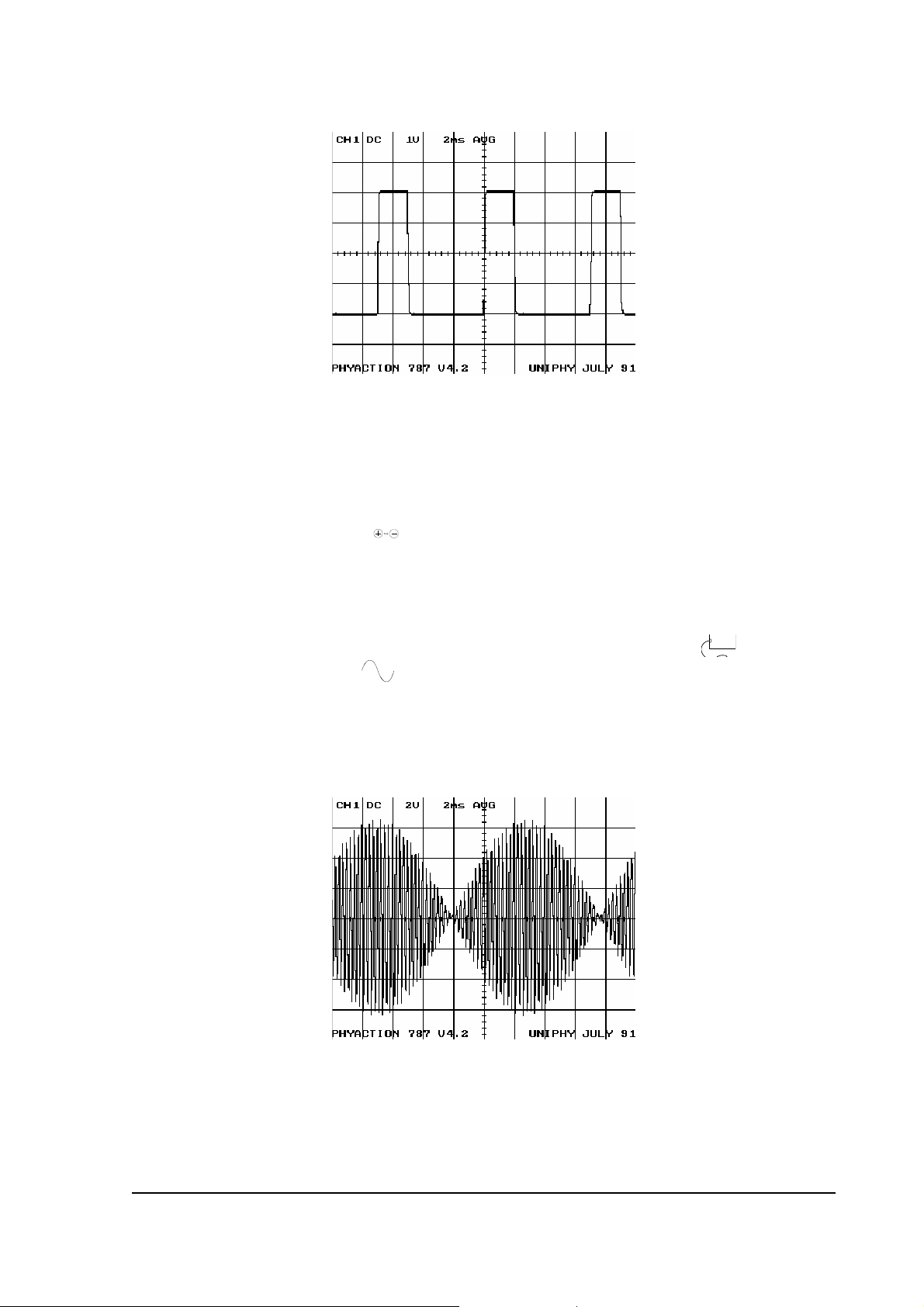
6. Select program 5 (Ultra Reiz). Then, push blue button B X
10
(see display). Turn the dosage
regulator
6
on maximum output (80 mA) and check the type of current on the scope. The pulse
time has to be 2 ms and the pause time 5 ms.
PERFORMANCE CHECK Service information Phyaction 787 - Page 2
7. Push on the polarity button
10
5 and check on the scope if the polarity of the output changes.
Also check if the two right output LED's
5
burn.
8. Turn the dosage regulator
6
back to 0 and turn on the vacuum regulator
9
a little. Turn the dosage
regulator
6
on and check if the vacuum output LED's (left 2 output LED's
5
) light up.
9. Turn the dosage regulator
6
back to 0 and turn the vacuum regulator
9
back to 6. Switch the
current mode switch
7
to ac 7 and select the first program (isoplanar vector).
10 Turn the dosage regulator
6
slowly to maximum output (140 mA) and check on the scope (2
Volt/div ; 2 msec/div):
- if the amplitude is adjustable with the dosage regulator
6
- if the wave shape is conform the picture below
11 Put the scope on "X deflection." (X/Y) and check if the phase movement is 90° (on the scope
you should see a circle now).
PERFORMANCE CHECK Service information Phyaction 787 - Page 3
12 Turn the dosage regulator
6
back to 0. Return to the main menu via button
12
and select program
2 (dipole vector). Return to the submenu via button
13
and select AUTO. On the display you will
see a rotating bar.
Turn the dosage regulator
6
on. Put the scope on "Xdelf." (X/Y) and check if you can also see the
rotating bar on the scope.
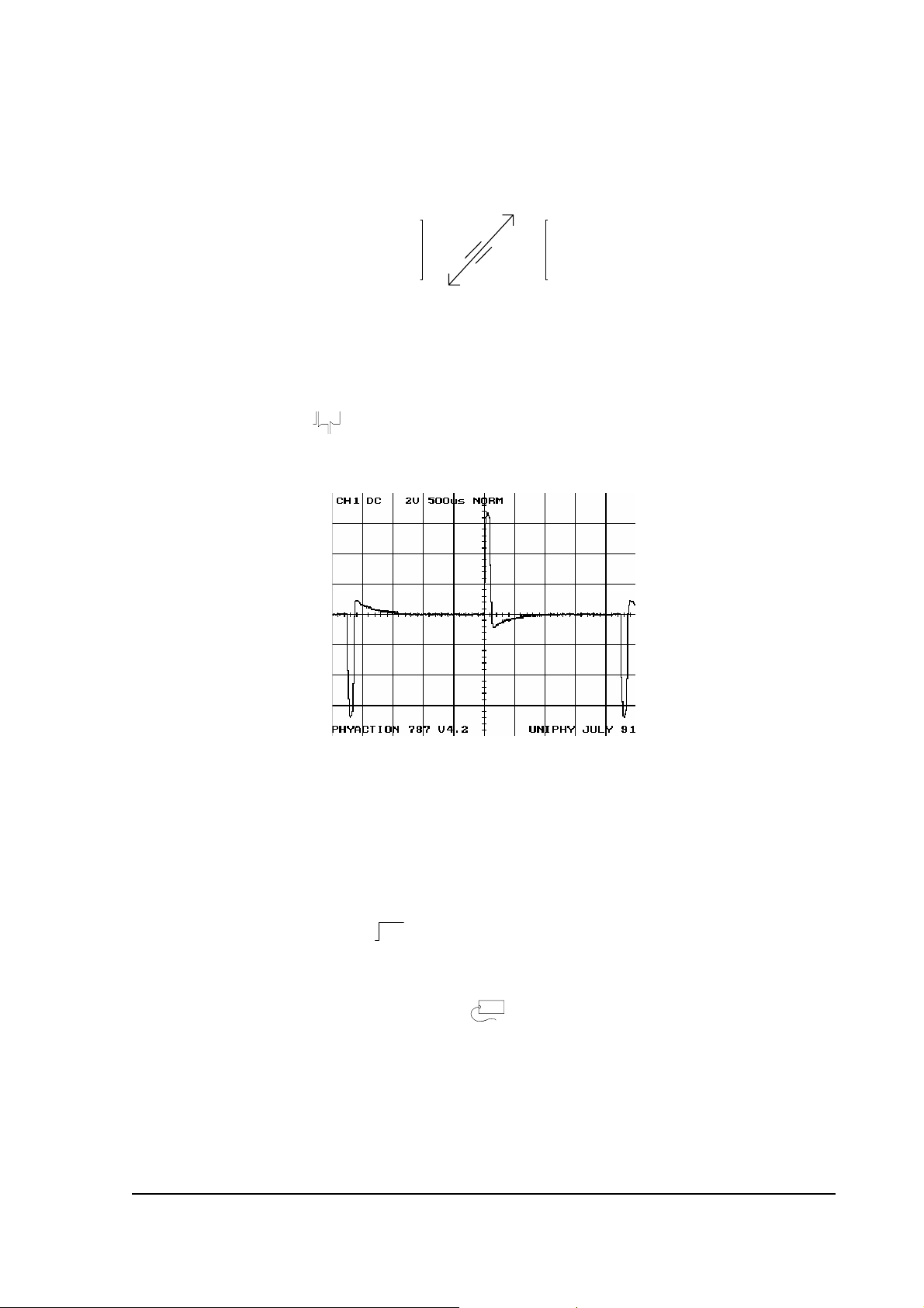
13 Turn the dosage regulator
6
back to 0. Adjust the scope to 0,5 ms/div and (x/t). Go to the main
menu via button
12
and select program 6. Select possibility 2 (random). Go to the submenu via
button
13
and select 10. Go to the next submenu via button
13
and push button B X
10
.
14 Turn up the dosage regulator
6
and check the type of current.
15 Remove the output plug and connect the vacuum meter to all tubeconnectors.
Select a program and turn the vacuum regulator
9
slowly to maximum.
- Check if the vacuum is properly adjustable up to 0,3 bar.
- When the vacuum reaches the 0,3 bar, then listen if the pump stops.
- Go to the vacuum adjustments via button
13
and select 2.
- Check if the vacuum reaches up to 0,5 bar and returns to 0,3 bar. This cycle lasts about 2
seconds.
16 Select continuous vacuum
10
12 and release one of the tubes from the vacuum meter. Keep
the tube closed (by folding it) and check if the tubeconnector is not choked. Put the tube back
and check the other tube connectors in the same way.
17 Put the vacuum regulator
9
back to position 13 and remove the vacuum meter. Switch off
the appliance with the on/off switch
17
en remove the mains cable.
 Loading...