

GymnaUniphy Phyaction V Service manual
Service manual Phyaction V
1. Contents
............................................................................................................................. 1 Contents
1.
............................................................................................................................... 2 Preface
2.
.............................................................................................................. 3 Important remarks
3.
................................................................................................................ 3 Safety aspects
3.1
.............................................................................................................. 3 Data registration
3.2
.................................................................................................................... 5 Technical data
4.
.................................................................................................... 5 General technical data
4.1
................................................................................................ 5 Environmental conditions
4.2
.................................................................................................... 5 Transport and storage
4.3
............................................................................................................... 6 Circuit description
5.
.................................................................................................................. 6 Power supply
5.1
.................................................................................................. 6 Patient Current Routing
5.2
........................................................................................................................... 6 Vacuum
5.3
............................................................................................................ 6 Control Loop
5.3.1
........................................................................................................ 6 Pulsed Vacuum
5.3.2
..................................................................................................... 7 End of Treatment
5.3.3
................................................................................................. 7 Water management
5.3.4
............................................................................ 8 Safety inspection list ( yearly check-up )
6.
................................................................................................................. 9 Hardware labels.
7.
....................................................................................... 9 Upgrading the hardware code.
7.1
................................................................................................. 10 Replacement procedures
8.
............................................................................................................ 10 Opening the unit
8.1
.............................................................................. 11 Replacement of power supply PCB
8.2
..................................................................................... 11 Replacement of the Main PCB
8.3
.......................................................................................................................... 12 Upgrades
9.
.................... 12 Vacuum pump switches of after 2 minutes even when current is flowing
9.1
.................................................................................................................. 13 Spare parts list
10.
............................................................................................. 13 Schematics and PCB layout
11.
Service manual version 0.1 Page 1

Service manual Phyaction V
2. Preface
The Phyaction V is a Uniphy “low noise” vacuum unit with following characteristics :
Vacuum unit with 2 independent channels.
2 or 4 poles
Electronic vacuum control
Continuous and pulse mode
The Phyaction V unit can be connected to the following Gymna electrotherapy units :
Phyaction C
Phyaction E
Phyaction I
As a member of the Uniphy family it is built according to the requirements of the MDD security
standards. All functions of the unit are controlled by a microprocessor, ensuring a high degree
of reliability and safety.
This service manual gives a complete and accurate technical picture of the Phyaction V.
In doing so, it will hopefully help you to reach your goal: to form a correct diagnosis and to solve
the client’s problem as thoroughly as possible.
If you have any questions or if you need additional information about this manual or about the
use of the unit, please do not hesitate to contact us.
Service manual version 0.1 Page 2
Service manual Phyaction V
3. Important remarks
3.1 Safety aspects
To understand and practice all procedures described in this manual a good technical
background is a must.
GymnaUniphy cannot be held responsible for any actions executed on the unit by unauthorised
persons, or for executing any procedures not prescribed in this manual.
All information in this manual has a GymnaUniphy nv. copyright.
3.2 Data registration
The distributor must be able to provide the following data for each unit:
Instrument data: Part and serial number.
Gymna has the original configuration of each unit.
The Phy
All these parts have a serial-or batchnumber that has to be filed in case of a configuration
change :
Customer data: Name, full address and date of delivery.
Service activities: All service activities must be filed.
If any critical parts are changed, we also expect the distributor to file the new serial
numbers of these part(s).
To file this data, a data registration document is available on next page.
action V has following critical parts:
Ref 324597 : Main PCB Phyaction V
Ref 138103 : Pump Vaco 200
Ref 324826 : Power supply SMPS Vaco 200
Service manual version 0.1 Page 3
Service manual Phyaction V
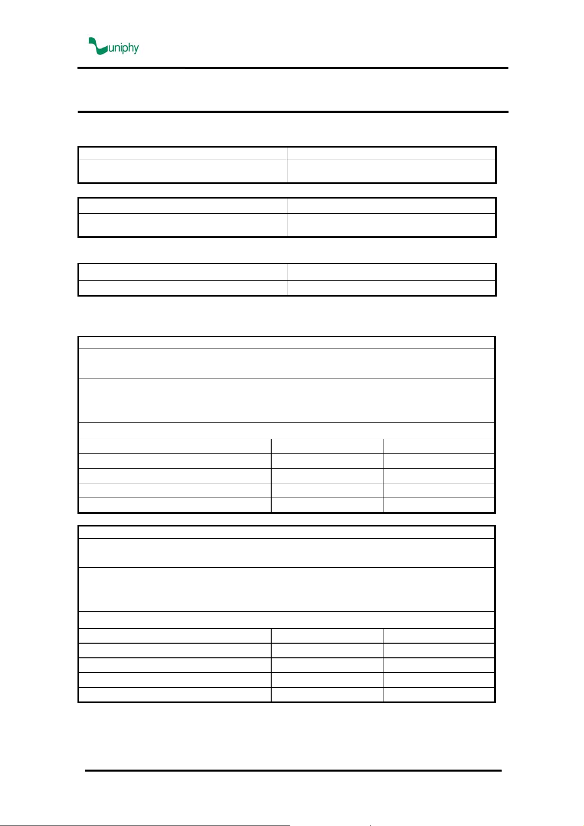
Data registration document
Information
Distributor name Distributor address
Customer name Customer address
Instrument name: Serial number:
Date of delivery:
Service activities
Date:
Error complaint:
Service action
Critical spare parts exchange list
Critical part name Old serial number New serial number
Date:
Error complaint:
Service action
Critical spare parts exchange list
Critical part name Old serial number New serial number
Service manual version 0.1 Page 4

Service manual Phyaction V
4. Technical data
This is a summary of the technical data as described in the user manual.
4.1 General technical data
Dimensions Phyaciton V (w x h x d) 267 x 95 x 270 mm
Weight Phyaciton V 3,5 kg
Weight including accessories 4,6 kg
Mains voltage 100 - 240 VAC, 50 - 60 Hz
Maximum power consumption 30 VA
Safety class Class I (earthed socket required)
Insulation Type BF (floating patient circuit)
Fuses 2 x T2AL250V
Volume water reservoir 180 ml
Working pressure continuous vacuum 38 - 320 hPa
Working pressure pulsation vacuum 58 - 480 hPa
Vacuum rhythm 1,5/1,5 - 1,5/4,5 s (on/off time)
4.2 Environmental conditions
Temperature: +10 °C to +40 °C
Relative humidity 30% to 75%
Atmospheric pressure 700 hPa to 1060 hPa
4.3 Transport and storage
Transport weight 6,5 kg
Storage temperature -20 °C to +60 °C
Relative humidity 10% to 100%, including condensation
Atmospheric pressure 200 hPa to 1060 hPa
Transport classification Single piece by mail
Service manual version 0.1 Page 5

Service manual Phyaction V
5. Circuit description
5.1 Power supply
The device is mains powered. It sports an all-range off-line switched mode power supply ,
meaning it can be used all over the world without having to select a working voltage or
frequency. But of course the the plug of the power cord has to fit into the local outlet type.
5.2 Patient Current Routing
The electrotherapy outputs of the main unit are connected to the vacuum unit, at the rear, and
the electrodes are connected to the front of the vauum unit. As long as the vacuum is not used
the traditional electrodes function as before, even when the vacuum unit is not switched on.
As soon as the vacuum is turned on the patient current is switched from the traditional
electrodes to the connectors for the hoses at the other end of which the suction cups are. In the
hoses is a wire that feeds the patient current to a metal plate inside the cup. Contact with the
the skin of the patient is established by a moisturized sponge. The switchover always happens
for channel A but the operator can add channel B by pressing a button that toggles the choice
between traditional and vacuum electrodes.
5.3 Vacuum
When the vacuum control is turned up, air is pumped out to create the vacuum until the set
level is reached. The hose connectors limit the air flow into each hose so one can put the
vacuum electrodes one at a time in their place. When channel B is not used, its connectors
should be plugged by connecting them to each other by a hose, otherwise the pump keeps
running and deeper vacuum levels cannot be reached.
5.3.1 Control Loop
A pressure sensor measures the vacuum level and a control loop powers the pump if the set
level is deeper or opens a valve to let air in when lower . In continuous mode this results in only
the pump being run very lightly, making up up for the small air leakage between the cups and
the skin and at the connectors.
5.3.2 Pulsed Vacuum
When the electrodes are in place the operator can pulsate the vacuum to mitigate the effect
vacuum has on patients with a vulnerable skin. When pulsating, the vacuum is raised by 50%
during 1.5 second and then returns for 1.5 to 4.5 seconds to the level set for continuous
operation. As a result the pump will run during the 1.5 second period of deepened vacuum after
which the valve will be opened until the base level is reached again.
Service manual version 0.1 Page 6
 Loading...