


1. Contents.
Contents. .....................................................................................................................................1
1.
2.
General........................................................................................................................................2
3.
Tools ............................................................................................................................................3
4.
Hardware evolution of Thermatur 200....................................................................................4
5.
Software evolution of Thermatur 200. .....................................................................................5
6.
Operating voltages .....................................................................................................................6
6.1 Mains power ............................................................................................................................6
6.2 Operating voltages coming from power supply PCB (A 100).................................................6
7.
Generator checkup and adjustment procedures in standby mode: STEP 1. .....................9
7.1 Generator power supplies ........................................................................................................9
7.2 Adjustment of +15 VDC........................................................................................................10
7.3 Zero point calibration. ...........................................................................................................10
7.4 Oscillator check .....................................................................................................................11
7.5 Check and repair of potentiometer R52.................................................................................11
7.6 Collector voltage regulator. ...................................................................................................12
8.
Generator check-up and adjustment procedures during operation: STEP 2. ..................13
8.1 Checking the collector voltage regulator during operation ...................................................13
8.2 Minimum power adjustment..................................................................................................13
8.3 Maximum power adjustment. ................................................................................................13
8.4 Self-oscillation problems.......................................................................................................15
8.5 Current consumption. ............................................................................................................15
8.6 Problems with accessories .....................................................................................................16
8.7 Harmonic filter PCB..............................................................................................................17
8.8 Output circuit (A300) ............................................................................................................17
9.
Generator replacement procedure. ........................................................................................18
10. Error codes. ..............................................................................................................................19
11. Checkup procedure of BLW96. ..............................................................................................20
January 2002 Version 0.3 Page 1

2. General
This Thermatur 200 repair guide will help you to recognize and solve most of the problems with
Thermatur 200.
However, in addition to this manual, a detailed service training is a must. Please contact our service
department for more information:
GymnaUniphy service department
Pasweg 6a
3740 Bilzen, Belgium
General Fax number service dept: 0032/89.510.561
Technical questions:
Tel: 0032/89.510.563
Service@gymna-uniphy.com
Spare parts:
Tel: 0032/89.510.523
Spareparts@gymna-uniphy.com
January 2002 Version 0.3 Page 2
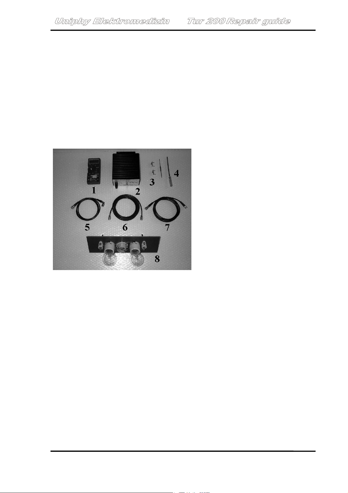
3. Tools
1. Digital calibrated multimeter (10 A DC min.)
2. Dummy load 50 Ohms (ordering ref: 08763)
3. LED mismatch detector
4. HF screwdriverset
5. Patient cable for plode 8 or 14 cm (new model)
6. Lambda/2 cable (Lenth 3630 mm): ref 15335
7. Patient cable for plode 8 or 14 cm (old model)
8. Lamp dummy load
January 2002 Version 0.3 Page 3

4. Hardware evolution of Thermatur 200
Version A:
Initial version.
Starting in all units from SN 10 (01/1992)
Version B:
Modification of tuning capacitor.
Capacitor is divided in 2 parts:
- Fine adjustment capacitor plate
- Coarse adjustment capacitor plate
This will result in a more ‘stable’ tuning during the treatment since the unit can change the capacitor
value in smaller steps.
This modification was introduced together with the release of software version 6.2.
For 230 V units: starting from SN B852 (05/1996)
For 115V units: starting from SN B5047 (05/1996)
Power supply FUBA 702
New, smaller PCB (for more information: chapter 4.1.2)
For 230V: starting from units with SN B1253 (01/1999)
For 115V: starting from units with SN B5101 (04/1999)
Power supply FUBA 702A
Same as FUBA 702, but with adjusting potmeter.
For 230V: starting from units with SN B6058 (12/1999)
For 115V: no information
Version C:
Amplification of SUM/DIFF of A 200 from 1 to 0.82. The generator A 200 remains forwards and
downwards compatible.
For 230V: starting from units with SN C6168 (06/2000)
For 115V: no information
January 2002 Version 0.3 Page 4

5. Software evolution of Thermatur 200.
V 6.0:
Initial version: from 12/1991 to 09/1992
V 6.1:
Improved keyboard function. From 10/1992 to 04/1996
V6.2:
Together with hardware modification to version B.
Indication of intensity: displays set power and not the real power.
For 230 V units: starting from SN B852 (05/1996)
For 115V units: starting from SN B5047 (05/1996)
V 6.3:
Special version. Indication of peak power (max: 400 watts)
For 230 V units: only for SN 6209 to 6217.
V 6.42:
For units delivered in 2002.
In version 6.2, the error message FE6 showed up in case of strong patient movements during a
treatment. This problem is solved in version V6.42.
In case of a poor tuning (SWR>6), the unit will start searching for a better position of the tuning
capacitor, just like it does when starting a treatment (full turn).
In case of SW V6.2, the unit could hang up (oscillation). This problem is solved in version V6.42.
The range in which the generator starts oscillating is reduced.
January 2002 Version 0.3 Page 5
6. Operating voltages
Before any repair work shall be done, it is important to check the operating voltages.
6.1 Mains power
When the unit is powered up, both the mains switch and the display will light up. If not check the
mains fuses (F001/F002) and replace with the same type:
230 V: SP 6.3A fast (ceramic pipe)
115 V: FST 6.26A, slow (glass pipe)
6.2 Operating voltages coming from power supply PCB (A 100)
What you need to know:
There are 3 different versions of power supply PCB (all switched PS).
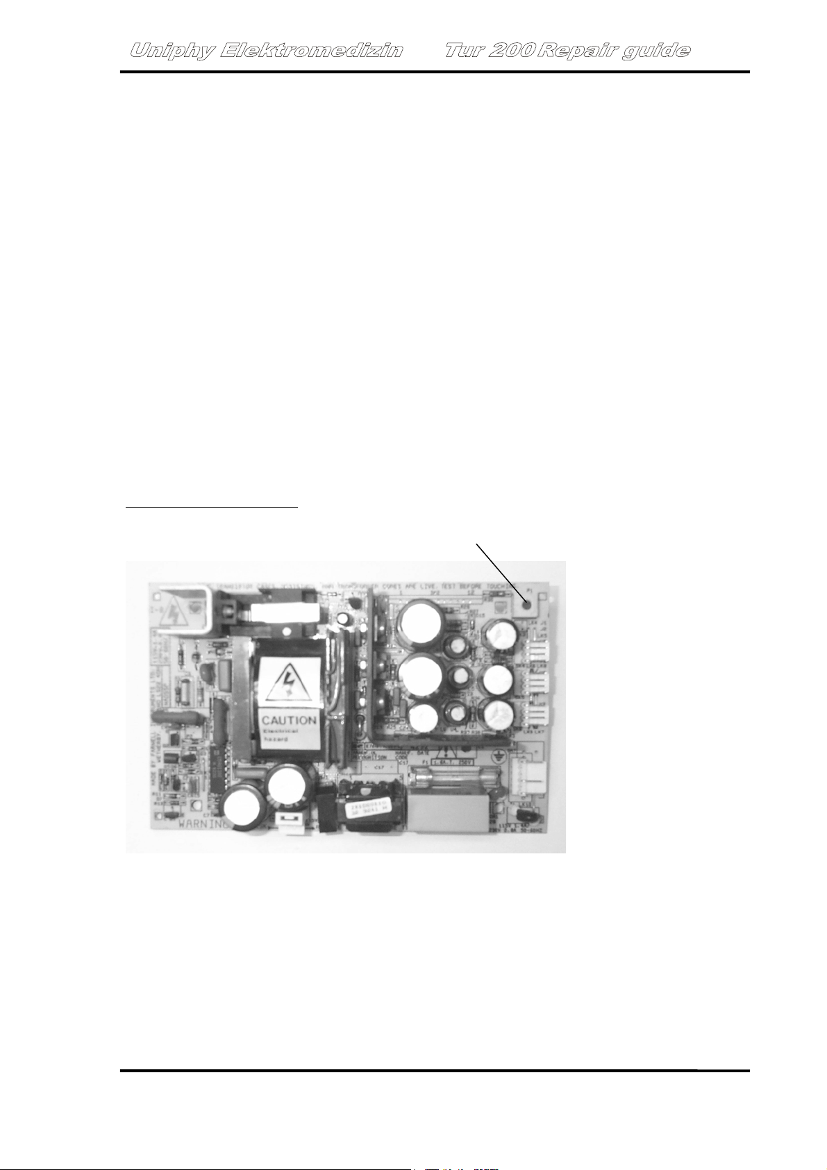
Power supply initial version
: big PCB with adjustment potentiometer. Not compatible with other
versions.
potentiometer
Photo 1
January 2002 Version 0.3 Page 6
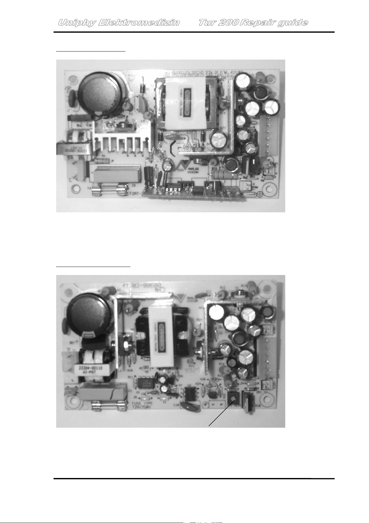
Power supply FUBA 702: small PCB without potentiometer
Photo 2
Measuring points:
Orange-black: +5V DC
Brown-black: +15.05 VDC
Power supply FUBA 702A
: same as FUBA 702, but with adjustment potentiometer.
Photo 3 Potentiometer
January 2002 Version 0.3 Page 7

230V: starting from units with SN B6058
The FUBA 702 power supply is fully compatible with the FUBA 702A board.
/
/ All the units starting with SN 6xxx are manufactured by Uniphy ELMED. Units with SN <6xxx
are manufactured by TUR.
January 2002 Version 0.3 Page 8

7. Generator checkup and adjustment procedures in standby mode
STEP 1.
The first step of checking/repairing the Thermatur 200 has to be performed in standby mode.
7.1 Generator power supplies
Photo 1. All measured in standby mode.
Between 1and 2: 44 VRMS- 48VRMS (AC)
Between 3 and 4: 25 VRMS- 28VRMS (AC). If this voltage = 0V, check fuse F003 on mains
transformer.
Between 5(+) and 6 (-): 30 VDC
:
Photo 4
Measurements on RF generator (A 200).
Ground level = X1 or aluminium chassis. All voltages are measured against ground.
/
X 9: - 15 VDC = blue wire
X 6: +15 VDC = brown wire
January 2002 Version 0.3 Page 9

7.2 Adjustment of +15 VDC
The most important is +15 V. Always adjust it to 15.05 VDC (in standby mode!) on the power
supply PCB (chapter 7.2).
For version 2 of power supply PCB (without adjustment potentiometer): check the voltage. If there is
a strong deviation, replace the board.
In case of a generator replacement, always check/adjust the +15 VDC supply to 15.05 V
/
(chapter generator replacement) and correct the zero point calibration.
7.3 Zero point calibration.
The measuring of RF power is performed by the multiplexing IC NO2 (IC KP 525 PS) Point 1 photo
x.
In order to have a correct measurement and a proper functioning of the generator, the zero point
settings (offset corrections) have to be calibrated.
Procedure:
- Draw off X11 and X12
- Switch on the unit (standby mode)
- Adjust 15.00V to 15.05 V between X6(+) and ground X10.
- Connect X14 and X15 to ground (X13)
- Connect X15 to +5V (photo 5) and X14 to ground
- Connect X14 to +5V and X15 to ground
Adjust 0.00V at X16 by R5
Adjust 0.00V at X16 by R4
Adjust 0.00V at X16 by R3.
Photo 5: 5V (right rear side of unit)
January 2002 Version 0.3 Page 10

7.4 Oscillator check
The 27.12 MHz oscillator can be checked at the collector of transistor V9 (cooling surface of V9).
Measure this signal with an analog oscilloscope, AC.
The voltage must be tuned between 12 Vpp and 14 Vpp by L10 (photo 1,
Adjustments and repair:
No oscillator frequency at all: replace Q1
Oscillator frequency out of limits: adjust coil L11 with small screwdriver.
7.5 Check and repair of potentiometer R52.
Due to RF power, some potentiometers might get a burn-in problem. This problem is typical for R52
and the result is always the same: no output power.
How to check whether this potentiometer is broken:
There are 2 different types of potentiometer: 47 Ohm and 100 Ohm
Switch off the unit
and measure both sides of the potentiometer (no need to take it out !)
A
C
B
Measure the following resistances:
A-C + C-B = 100 Ohm or 47 Ohm (more or less
If not: replace potentiometer.
/ Important: always put the new resistor in the same position. If you switch from 47 Ohm to 100
Ohm, always calculate the new position of the potentiometer in a way that the resistance of A-C is
the same as before.
)
January 2002 Version 0.3 Page 11

7.6 Collector voltage regulator.
Switch on the unit in standby mode.
Switch on the unit and wait 30 seconds (this is important).
Measure voltage on X 205 (red wire) and earth X206 (black wire or aluminium generator housing).
Voltage on X 205: fluctuating between 10 VDC and 14 VDC
Mark the position of potentiometer R55
Turn R55 counter clockwise and check DC voltage: maximum voltage must be between 24 VDC and
26 VDC. If not, replace IC B4707 and check again.
After replacement, check proper functioning and calibrate when necessary (8.2.2)
January 2002 Version 0.3 Page 12

8. Generator check-up and adjustment procedures during operation
STEP 2.
Always perform complete check-up procedure STEP 1 (chapter 9) before performing step 2.
All measurements are performed directly on the generator by means of a 50 Ohm dummy load.
/ Always make sure that the dummy load doesn’t heat up because it will influence the measured
voltage on the dummy load !
8.1 Checking the collector voltage regulator during operation
The collector voltage of the amplifier BLW96, depends on the output power. The following
procedure explains how to check and correct this value.
Connect the 50 Ohm dummy load directly to the generator.
Switch on the unit and select the triplode, continuous mode, 5 min. and raise intensity:
Output power
(Watts)
0 about 13 V
50 about 29 V
100 about 36 V
150 about 41 V
200 about 44 V
In case of a strong deviation, this voltage can be corrected with R 55.
Voltage at X205
(Volt)
:
8.2 Minimum power adjustment.
The minimum output power of thermatur 200 is 9 Watts. The procedure below explains how to
measure and calibrate this value.
Connect the 50 Ohm dummy load directly to the generator.
Connect a multimeter to the output connectors of the dummy load (DC voltage).
Switch on the unit and select the triplode, continuous mode, 5 min. and set to minimum power (9
Watts):
The voltage on the multimeter must be between 3.0VDC and 3.2VDC. Correct this voltage with
potentiometer R65 that is mounted on the display PCB!
The tuning bargraph has to be lit completely!
/ No need to take out the display PCB: there is a hole in the PCB that allows to correct R65.
8.3 Maximum power adjustment.
The maximum output power of thermatur 200 is 200 Watts. The procedure below explains how to
measure and calibrate this value.
Connect the 50 Ohm dummy load directly to the generator.
Connect a multimeter to the output connectors of the dummy load (DC voltage) (Photo 6)
Switch on the unit and select the triplode, continuous mode, 5 min. and raise intensity.
January 2002 Version 0.3 Page 13

Output power
(Watts)
50 about 7 V
100 about 10 V
150 about 12 V
200 about 14 V
Step 1: Correct the output power with R2 on the generator PCB.
Step 2: measure the voltage on X7 and X8. The value measured on X8 must be equal to X7/2.
Correct this value with R21 in combination with R2 (alternating)
Repeat the measurement of step 1 since this correction will have influence on the measurements of
step 1.
Voltage measured
on output dummy
load (Volt DC)
Photo 6
In case of no output power at all: check 9.1 (collector voltage regulator).
January 2002 Version 0.3 Page 14

8.4 Self-oscillation problems.
Self-oscillation of the generator might cause a bad tuning between the unit and the patient, or might
cause an error code FE2, FE3 or FE4.
The reason of this oscillating problem might be the unit or the accessory.
How to check if the unit is oscillating.
Connect a reference accessory to the unit and perform a test. If the reference accessory is working
fine (at least 8 digits on tuning bargraph), then the original accessory needs to be recalibrated. Send
to our service department for calibration.
If the problem appears to be the same with the reference electrode, the generator might be oscillating.
Perform the steps below:
- Connect the thermoplode directly to the generator by means of the Lambda/2 cable.
- Put the plode on a patient, on a spot where full tuning can be expected.
- Raise intensity to maximum allowed for that particular accessory.
- Count the number of digits on the tuning bargraph.
- Take the plode away from the patient and put it back on the same spot.
- If the tuning bargraph indicates less digits than before (in point 4) than the generator is
oscillating: replace generator (Ch. 11)
- If the tuning barhgraph was indicating less than 6 digits in the first place (point 4) replace the
generator as well (Ch. 11)
- If the result of this test seems to be OK, check the harmonic filter PCB (Ch. 9.2) and the
output circuit (Ch. 9.3)
8.5 Current consumption.
Measure the following DC currents with a DC multimeter (10A DC scale)
/ this value can only be measured with a moving coil current measuring instrument, or with a digital
multimeter in case a 50 Ohm dummy load is connected.
- X6 (brown wire) : typical <=1.2 A with 200W output power
- X5 (red wire): typical < 6,6 A with 200 W output power
/ In case of strong deviations: replace the generator (Ch. 11).
January 2002 Version 0.3 Page 15

General checkup procedures
If, after a successfully check and adjustment of step 1 and 2, the unit is still showing problems with
tuning or output power, there are 3 more possible causes.
- Problems with accessories
- Problems with harmonic filter (A500)
- Problems with output circuit board (A300)
8.6 Problems with accessories
The best way to check an accessory is simply to check the unit with a reference accessory (a new
one).
When the problem appears to be the same with the new accessory, perform the test below:
For coil field electrodes:
Connect a coil field electrode (8 cm, 14 cm or triplode) directly to the generator by means of a
lambda/2 cable.
Raise intensity to maximum allowed power (8cm: 30 W, 14 cm: 90 W, articulated plode: 200 W)
while putting the plode on a patient (the surface must me at least as big as the surface of the plode)
Now check the tuning bargraph: at least 8 led’s must be on. If not: the problem might be the
generator: perform all the tests as explained in chapter 8 and 9. Replace the generator if necessary.
When at least 8 LED’s are on, connect the plode to the normal output connector (rear side of the unit)
and compare. When less than 8 LED’s are on, perform the check as explained in 10.2 and 10.3.
For capacitor electrodes:
Connect the lamp dummy load to the unit (photo7) and open the back cover completely.
Switch on the unit and raise power up to 200 Watts.
Now check if the lights are fully on and stable.
If not; perform the check as explained in 10.2 and 10.3.
Photo 7
January 2002 Version 0.3 Page 16

8.7 Harmonic filter PCB.
Typical for this PCB are bad soldering connections. They may even not be visible without a
microscope, but they may influence the tuning in a negative way.
Resolder the soldering points of the big coils.
Another problem might be the capacitors. Check for short circuit, and replace capacitors when
necessary.
Touch each capacitor with a small screwdriver. If on them brakes off: replace.
8.8 Output circuit (A300)
The output circuit board contains a big variable capacitor, driven by a stepping motor.
The capacitor has a main part (7 plates) and a fine tuning part (1 plate). When the motor is only
turning slightly, only the fine tuning capacitor plate will turn. When the motor starts rotating, all the
capacitor plates will turn.
Open the back cover of the unit plus the aluminium cover of the capacitor electrode and connect the
lamp dummy load to the unit (photo7).
Now check the capacitor: only the fine tuning capacitor plate may turn up and down a little bit. The
big plates may not turn. If not, turn the screw (photo8) in the middle of the capacitor half a turn
clockwise and check again.
If necessary, readjust until the system works fine.
/: If the capacitor doesn’t turn at all, the motor pulley might be unfixed. Refix the pulley and check
again.
Photo 8 fine tuning capacitor plate (1 plate)
Main capacitor plates (7 plates)
January 2002 Version 0.3 Page 17

9. Generator replacement procedure.
If al the repair and calibration procedures may not solve the problem, the generator might be broken.
In case of a generator replacement follow the steps below:
- Mark the cable connections of the generator before disconnecting the wires.
- Desolder the wire on the thermistor (right side of the generator)
- Remove the screws that fix the generator (2 on the bottom and 1 on the right side)
- Take out the generator.
- Repeat step 2-4 in reverse order.
- Adjust +15V to 15.05 V (procedure in chapter 8.2)
- Perform the 0 point calibration (procedure in chapter 8.3)
- Perform test with lamp dummy and accessories (procedure in chapter 10.1)
/ When sending back the defective generator, always send it together with the heatsink and cover
plate and pack it very carefully !!!
January 2002 Version 0.3 Page 18

10. Error codes.
11.
Error
code
FE 2 - Pspec=0; Pact>0
- Control input Uin or measuring
FE3 - Pact>Pspec +5Watt
- Generator is oscillating
FE4 - Pulse function is disturbed. The
FE6 - Pact(measured)<Pspec
- No signal at Up
- Excessive load fluctuations
FE7 - Excessive operating voltage of the
FE8 - Operating voltage of the power stage
FE9 - Interruption of the thermistor circuit
FEa - Signal Us+Ud is missing
- +15V is missing
FEb - Generator is overheated
FEc - Emergency switch was activated or
FE - Not all parameters are set.
Description Possible cause
input is open
pulse pause power is too high.
power stage.
is too low
R0003
the circuit of emergency switch is
interrupted
The microcontroller measures power, while
the intensity settings are 0. This might be a
problem with the zero adjustment (CH 7.3).
Most of the time a generator oscillation fault
(Ch. 8.4)
Perform zero adjustment (Ch. 7.3) and power
measurement of generator (Ch 8.2/8.3). Most
of the time a generator oscillation fault (Ch.
8.4)
Perform zero adjustment (Ch. 7.3) and power
measurement of generator (Ch 8.2/8.3). Most
of the time a generator oscillation fault (Ch.
8.4)
The measured power is smaller than the set
power. Perform 9 Watt adjustment (Ch 8.2)
Generator might be oscillating(Ch. 8.4)
Collector voltage of BLW96 >50V.
Check voltage control circuit (manual page)
Collector voltage of BLW96<6V
Check voltage control circuit (manual page)
and fuse F003.
Check leads of the thermistor R003.
Resistance should be +/- 1K6 at room
temperature.
Probably generator gives no output power.
Oscillator does not work work, R 52 maybe
defect (Ch. 7.5) Check and replace generator
if necessary.
Check fan and perform general check-up of
unit.
- Replace emergency switch when necessary.
User error. Select time, accessory and mode.
12.
January 2002 Version 0.3 Page 19

13. Checkup procedure of BLW96.
In case of no emission of the generator. The BLW 96 might be broken.
In order to make sure, please perform the test below.
1 .
4
o 3
BLW
4
- Disconnect pin 1 and 4.
- Measure diode on both directions between all the junctions (1-2, 2-3, 3-4, 1-4, 2-4, 1-3). One
direction must emit and the other must block. If not: BLW is broken.
/ Important remark: the BLW96 cannot be replaced, due to the fact that the generator needs to be
recalibrated.
Replace generator.
January 2002 Version 0.3 Page 20

A200 Generator PCB Layout
X11
X7
X8
X13
X7X12
X14
X15
X18
X16
R21
N3
R4 R5 R3 R2
-15V
X9
X3
X5
N2
N1
R21
X14
X14
X15
X17
X18
N3
X16
R1
R55
R61
R60
C2
R55
+15V
X1
X4
X2
X10
X6
V09
V09
Y13
BLW 96
L16
L16
Y12
BLY 93
R52
R52
 Loading...