

GymnaUniphy Phyaction Supporta Service information

Copyright© Uniphy BV 1997-1997
Phyaction® is a registered trademark of Uniphy BV
Art. Code 93004950.1
Phyaction is manufactured in The Netherlands by Uniphy BV
P.O.Box 558 , NL-5600 AN Eindhoven, the Netherlands
Tel. +31 499 491802 Fax. +31 499 474734
SERVICE INFORMATION
PHYACTION SUPPORTA

Table of contents
CHAPTER 1
1.1 Introduction ........................................................................................................ 1
1.2 Safety test ......................................................................................................... 1
CHAPTER 2
2.1 Introduction ........................................................................................................ 2
2.2 General block diagram ......................................................................................... 2
CHAPTER 3
3.1 Safety inspection ................................................................................................ 8
3.2 IEC 601-1 safety tests..........................................................................................9
CHAPTER 4
4.1 Introduction ...................................................................................................... 10
4.2 Description of the automatic selftest ................................................................... 10
4.3 List of error messages ........................................................................................15
4.4 Adjustment procedures ....................................................................................... 16
4.5 Jumper Settings Supporta................................................................................... 16
CHAPTER 5
5.1 Introduction ..............................................................................................17
5.2 Replacing the battery pack ........................................................................17
5.3 Exchanging the software............................................................................17
5.4 Replacing the main board. PCB 492X .......................................................... 17
5.5 Exchanging the membrane panel or connector block .....................................18
CHAPTER 6
GENERAL INFORMATION
THEORY OF OPERATION
PERFORMANCE CHECK
TROUBLE SHOOTING
EXCHANGING BOARDS AND MODULES
CIRCUIT DIAGRAMS ...........................................
........................................................ 1
.......................................................... 2
............................................................. 8
................................................................ 10
....................... 17
19
Table of contents - Service information Phyaction Supporta

CHAPTER 1
1.1 introduction
The Phyaction Supporta is suitable for administering electrotherapy and ultrasound therapy, as well
as for a combination of both types of therapy. There is one 2-pole medium frequency interferential
current that can be applied. There are also two TENS currents, TENS continuous and TENS burst.
The ultrasound therapy can be applied with a 4 cm² or 1 cm² (optional) ultrasound head. It is
possible to use ultrasound therapy in combination with the interferential current or TENS
continuous.
For detailed information about the features and operation of the device we suggest that you should
read the user manual.
1.2 Safety test
To ensure the patient’s safety a safety test has to take place every time after the equipment has
been serviced. The Phyaction Supporta is a class II BF appliance. Carry out the safety test with a
safety tester that complies with the IEC 601-1 demands. See section 3.2 for further details.
GENERAL INFORMATION
1. GENERAL INFORMATION Service information Phyaction Supporta - Page 1
CHAPTER 2
THEORY OF OPERATION
2.1 Introduction
In this chapter the electronics of the Phyaction Supporta will be explained. A description on the
level of functional block diagrams will be used. The electronics will be described in more depth
when safety aspects are concerned.
The Phyaction Supporta is a device for ultrasound-, electro- and combinationtherapy. The user -the
physical therapist- can set a number of parameters. The parameters are converted in electric signals
for the ultrasound and electrotherapy circuits by a microcontroller.
The microcontroller continuously checks whether the ultrasound circuit produces the proper amount
of ultrasound power.
The microcontroller also checks the safety circuit each time the Supporta is switched on. Further it
checks the patient resistance during treatment to verify the patient current.
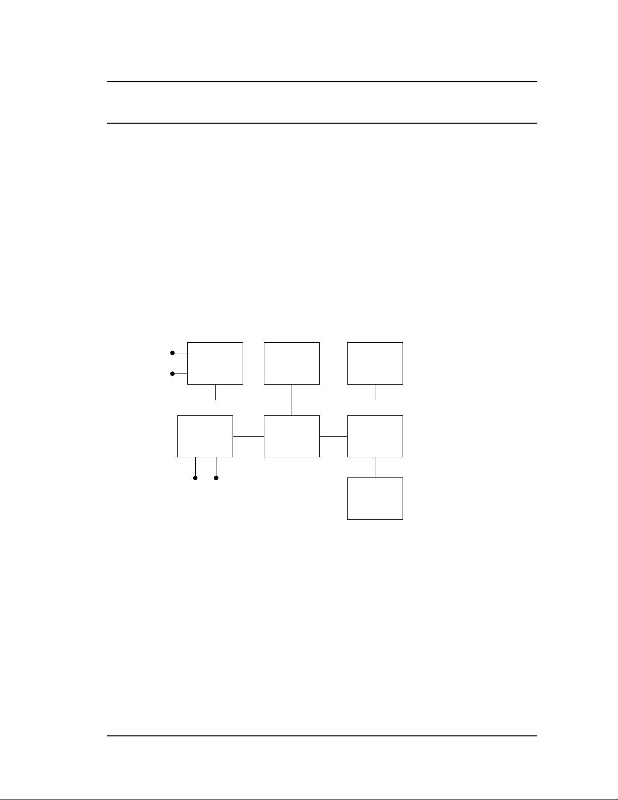
2.2 General block diagram
The block diagram of the Phyaction Supporta is shown in the figure below.
Charger
Mains
supply
Power
Supply
circuit
2.2.3
Electrotherapy
2.2.4
Current Outputs
User
Interface
2.2.2
Micro-
controller
core
2.2.1
Service
interface
Ultrasound
therapy
2.2.5
Ultrasound
head
The microcontroller core (µC) controls the complete device.
All interactions between the device and the user are executed via the user interface. The user
interface contains the switch panel, the ultrasound intensity knob, the LCD and the LEDs.
The power supply circuit selects the power source (a battery or a mains supply) and also converts
this voltage to 5 Volts. The device can be switched on with a switch at the back.
The electrotherapy circuit consists of a switch-mode power supply, a generator, the intensity knob
and the safety circuit.
The ultrasound circuit consists of a switch-mode power supply, a generator and a head
identification circuit.
The serial service interface is used for extended service features.
2. THEORY OF OPERATION Service information Phyaction Supporta - Page 2

2.2.1 The microcontroller core
The microcontroller used in the Phyaction Supporta is an 80C166. The 80C166 is a 16-bit RISC
controller with the following features on the chip:
- 1k byte RAM memory
- 5 timer / counters
- 10 channel 10-bit AD converter
- 76 general I/O lines
- 2 UART for serial data transfer (e.g. RS232)
- watchdog timer
- capture / compare system
Besides the microcontroller the following parts are present in the core:
- (32 kByte) RAM data memory
- 1 Mbit EPROM program and constant data memory
- 512 byte I
2
C E2PROM non-volatile data memory
- HCMOS IC's for decoding and buffering purposes
- a power-on reset circuit
2.2.2 The User Interface
2.2.2.1 The switch panel and LEDs
The switch panel is a matrix of 14 metal dome membrane keys, a matrix of 20 LEDs and two
single LEDs. The matrices of the keys and the LEDs are connected to the µC via a tail. The user
can use the keys to set and change a number of parameters such as pulse width, duty-cycle and
treatment time.
The top layer of the switch panel is made of polyester.
2.2.2.2 The ultrasound intensity control
See section 2.2.5.1,
2.2.2.3 LCD
An alpha numerical LCD with LED backlight is used for the display. During battery operation the
backlight will be switched off by the µC for power saving when no keys are pressed.
The LCD displays the treatment time and some parameter settings of the electrotherapy.
The contrast is controlled by the µC through a switched-capacitor voltage inverter.
2.2.3 The power supply circuit
2.2.3.1 The supply selector
If present the device is powered by the battery unless an active mains supply is connected. The
supply selector determines whether the battery or the mains supply is to be used.
2.2.3.2 The Battery
The battery consists of ten rechargeable NiCd cells with a capacity of 1.7Ah. The battery voltage
is typical 12 V with a maximum of 15 V. The battery voltage is monitored by the µC and it
switches the device off if the voltage drops to 10 V.
2. THEORY OF OPERATION Service information Phyaction Supporta - Page 3

2.2.3.3 The charger
The battery can be charged with an external charger which fully charges the battery in 14 hours.
The charger is a transformer and rectifier (without smoothing capacitor), generating a DC current
of 200 mA average. The open circuit voltage is approximately 24 Vdc.
The charger comes in 3 different models:
model 401 100 ...120 V with an American style mains plug
model 403 220 .. 240 V with an European style mains plug
model 404 220 .. 240 V with a British style mains plug
The charge current can only reach the pcb if a battery is connected, because this current is
routed through the battery connector which contains a shorting link.
2.2.3.4 The mains supply
The mains supply is a switch-mode power supply with a voltage of 18 V typical and a maximum
average DC current of 1.8 A.
The voltage supplied to the pcb must never exceed 20 V due to limited component voltages. The
voltage should be 16 V minimum, because at lower voltages the internal power source selector
will not operate properly.
2.2.3.5 Internal battery charger
When the mains supply is connected and a battery is present, a current source serves as internal
battery charger, charging the battery with approximately 170 mA.
2.2.3.6 The +5 V power supply
The voltage from the supply selector is converted to +5 V by a switch-mode power supply
(SMPS). This SMPS can be switched off by the controller, in case of a low battery voltage, with
the signal ‘5V-SD\’ (active low). After power-up there is a limited time in which the µC should
take over the SMPS enable signal from the bootstrap circuit. For fault finding purposes jumper
J101 ‘force 5V’ is provided. Shorting this jumper will keep the +5V up even if the µC fails to
assert the ‘5V-SD/’ signal.
2.2.3.7 The charge indicator
When the battery is charged the charge indication LED, on the console, is activated.
The circuit driving the LED is independent of the 5 V SMPS (see paragraph 2.2.3.6), because the
circuit (and the LED) should also work when the device is switched off.
2.2.4 Electrotherapy circuits
2.2.4.1 General
To ensure the safety of the patient both the µC and the safety circuit monitor the generated
current against the set value and limit value allowed by the IEC-standard.
2.2.4.2 Signal generator
The 4 kHz carrier wave of the MF signal is a square wave (not a sine wave) generated directly by
the µC. The amplitude modulation is done by an 8-bit multiplying DAC. This DAC is controlled by
2. THEORY OF OPERATION Service information Phyaction Supporta - Page 4

the µC with DMA-control. The reference voltage for the DAC is directly derived from the wiper
voltage of the current control potentiometer.
The TENS pulses are also generated by the µC. There is an additional hardware TENS pulse
limiter ensuring the pulse width not to exceed 200 µs and that the pulse frequency not to exceed
400 Hz.
2.2.4.3 Output stage
The signal from the signal generator drives the output stage. This circuit has two adjustments,
one for the maximum current of 100 mA peak and one for the minimum current of less than
300µA. The output stage consists of a transformer driven by 2 FETs with a very low on-
resistance, to limit the power loss. Because the losses in the FETs are very low no heat sink is
needed. A third FET is used exclusively for TENS generation operating as a gated current source.
2.2.4.4 Switch-mode power supply
The SMPS supplies the output stage with a voltage between 0 V and 5 V. In case of MF
current, the control circuit regulates the voltage of the SMPS in such a way that the set current
(ETset) flows, independent of the patient resistance. If the patient resistance is too high the
voltage will clip at 5V.
In case of TENS current the SMPS is set to maximum, because the control circuit is too slow to
follow the TENS pulses.
2.2.4.5 Intensity control
The electrotherapy intensity is set by a potentiometer with a switch. The switch signals to the
µC that the operator has put the control into operation. The position of the sweeper of the
potentiometer is a direct measure for the set value of the current. The sweeper is the reference
voltage (ETref) for the signal DAC. Also it is used for comparison with the read value of the
current by the safety circuit.
2.2.4.6 Safety circuit
In this circuit the primary output current is used to monitor whether the output exceeds the limit
peak
of 100 mA
or 150% of the set value by the intensity control. Also the intensity control is
monitored for interruptions of the ground and guard terminal. All the safety functions are
achieved by comparators, fully independent of the µC. In case of a fault the comparators switch
the safety relay off, which interrupts the patient current. Even in case of maximum intensity, this
will happen so fast that the energy contents of the resulting pulse will be below the allowed
limit. Once the safety relay has been switched off, it remains in this state and the device must be
switched off.
2.2.4.7 Reference voltages
There are two reference voltages in the safety circuit: 4.096 V, used for the safety comparators
and 2.50 V, used for the ET potentiometer and ET and US signal generation.
The reference voltage (ETref) for the DAC is derived from the 2.50 V via the electrotherapy
potentiometer.
2.2.4.8 Test control circuit
During the selftest of the device the safety circuit is tested: guard and ground connection of the
potentiometer, 150% and the limit, to ensure that the safety circuit works.
2. THEORY OF OPERATION Service information Phyaction Supporta - Page 5

During a fixed time the µC can activate the safety relay. After this time has expired, the µC can
only switch off the safety relay, e.g. when an error has been detected. The relay ‘De-energize’
ensures that no current can flow through the patient during the selftest.
2.2.5 Ultrasound circuits
2.2.5.1 The ultrasound intensity control
The ultrasound intensity is set by a potentiometer with a switch. Both the potentiometer and
switch are directly connected to the µC. From the position of the potentiometer the µC calculates
the amount of power that is to be supplied to the output stage. The switch signals to the µC that
the operator has put the control into operation.
2.2.5.2 PLL
The required ultrasound frequency of 0.7 MHz to 1.0 MHz is generated by a phase locked loop
(PLL). The PLL transforms the low-frequent signal (Refclk), generated by the µC, up to the
required drive frequency which is twice the ultrasound frequency. The modulator divides this
frequency by two and mixes it with the desired duty-cycle.
If the PLL is out of lock, the Lock-error signal (USerror\) is used to stop the modulator in order to
prevent erroneous frequencies produced by the treatment head.
2.2.5.3 The modulator
To obtain a symmetrical drive signal for the power stage, the modulator switches its outputs
with half the input frequency. Synchronously the modulator mixes the duty-cycle signal with the
ultrasound frequency.
With the Lock-error signal the modulator can be forced to shutdown if the PLL is out of lock.
2.2.5.4 The switch-mode power supply (SMPS)
The SMPS supplies the output stage with a voltage between 0 V and 5 V.
The SMPS for the ultrasound circuit is only active if the ultrasound therapy is chosen. The µC deactivates the SMPS via a shut-down (US-SD\).
The SMPS output voltage is linear proportional to its input voltage (Usset). Thus the µC can
change the ultrasonic power by setting Usset proportional to the square root of the desired
output power.
The µC continuously monitors the output voltage (USV) of the SMPS. If the output voltage is too
high e.g. due to a hardware failure, the µC will shut down the ultrasound circuit and give an error
message.
2.2.5.5 The power stage
The power stage is a switched half bridge. The generated output is controlled by USV, generated
by the SMPS. The above mentioned modulator controls whether the power stage is active.
Power MOSFETs are used as switching elements. The MOSFETs are driven by with a small delay
in the on-ramp, to prevent them of being active simultaneously.
2.2.5.6 Impedance matching
The ultrasound transducer shows mainly a capacitive load. Its impedance differs, among other
things, with the size of the transducer and its operating frequency. For this reason the µC can
match the impedance by switching one or two inductors in series depending on the head being
2. THEORY OF OPERATION Service information Phyaction Supporta - Page 6

used. To ensure that all devices give the same output, the coils, for both the large head and the
small head, are each adjusted to a specific inductance. Do not change this adjustment.
The µC monitors the match of inductor(s) and head by checking the current (USI) through the
MOSFETs. This current is proportionally to the current through the head. If there is a mismatch,
due to bad acoustic coupling, USI will increase and signal the µC to decrease the ultrasonic
power. The duty-cycle is set for the ultrasonic output power not to exceed 0.2 W/cm². When the
match is established ultrasonic output power is restored to the set ultrasonic power.
2.2.5.7 Ultrasound head
The ultrasound head converts the electric signal into ultrasonic vibrations. The transducer, with a
diameter depending on the head size, is glued in an aluminium cup that minimises
electromagnetic radiation and enables the transducer to be used on the operating frequencies.
The aluminium cup can also be used as a second electrode for combination therapy. A separate
electrode needs to be connected to the safety socket for combination therapy.
An OTP in the connector of the head enables the µC to detect whether a head is connected and
to recognise the type of head that is connected. This OTP also contains specific head related
information. Thus enabling the µC to set the head specific frequencies and ultrasonic power.
2.2.5.8 Head Identification Circuit
The head identification circuit enables the µC to read the contents of the OTP in the connector of
the ultrasound head. If the checksum calculated by the µC differs from the checksum in the OTP,
the head will not be recognised.
If a head parameter, necessary for the ultrasound circuit to generate the ultrasound power,
exceeds its limits, the µC will produce an error message.
2. THEORY OF OPERATION Service information Phyaction Supporta - Page 7

CHAPTER 3
PERFORMANCE CHECK
3.1 Safety inspection
This inspection is for technical maintenance purposes only. It is recommended that this test is
carried out once a year. If the appliance is serviced, the full IEC 601-1 tests have to be carried out.
A short description of these tests is given in section 3.2.
3.1.1 Visual inspection
Passed, when all applicable items are answered with YES.
yes no
Is the user manual there?
Is the casing of the appliance undamaged?
Is the label well readable?
Are the controls, display, lights and connectors all right?
Are the power input and the equipotentiality busbar all right?
Are ultrasound treatment heads, cables and connectors undamaged? (Pay special
attention to possible leaks in the treatment heads, such as cracks or loosened
seems.)
Are the labels on the ultrasound treatment heads readable?
3.1.2 Functional test
Passed, when all applicable items are answered with YES (or not applicable).
yes
Is the automatic selftest executed successfully at power on?
Is the appliance able to detect both treatment heads? 1 cm²
4 cm²
Is the ultrasound output correct for both treatment heads 1 cm²
at maximum intensity? 4 cm²
3.1.3 Test of the electrical safety according to VDE 0751
Parameter Measured value Limit Remarks
Enclosure leakage current
µ
A < 1000 µA
no
Patient leakage current
µ
A < 5000 µA
3. PERFORMANCE CHECK Service information Phyaction Supporta - Page 8

Also register the measured values in the device records and compare them with the values
measured in the past to alert for a possible potentially dangerous tendency.
3.2 IEC 601-1 safety tests
For the full description of these tests we refer to the IEC 601-1 (1988) for Class II, Type BF
equipment. Here is just a short reminder list of the tests and the test limits.
Measurements limits
Insulation resistance applied part
Enclosure leakage current normal
Enclosure leakage current open lead
Enclosure leakage current reverse
Enclosure leakage current open lead
Patient leakage current normal
Patient leakage current open lead
Patient leakage current reverse
Patient leakage current open lead
Mains on applied part normal
Mains on applied part reverse
Dielectric strength A.P. + CASE to MAINS *
Dielectric strength MAINS + CASE to A.P. *
> 2.0 MΩ
< 100 µA
< 500 µA
< 100 µA
< 500 µA
< 100 µA
< 500 µA
< 100 µA
< 500 µA
< 5000 µA
< 5000 µA
> 1500 V
> 1500 V
rms
rms
* These tests need only be executed if repairs have been made in the mains part or in the output
circuits.
3. PERFORMANCE CHECK Service information Phyaction Supporta - Page 9

CHAPTER 4
4.1 Introduction
If a Phyaction Supporta is defective, in most cases the unit will detect an error in the automatic self
test. A full description of this test will therefore help the service technician in finding the fault. In
the next section you will find this description. In section 4.3 you will find a list of all possible error
messages and possible causes.
TROUBLE SHOOTING
4.2 Description of the automatic selftest.
4.2.1 General
The selftest checks proper functioning of the safety relay and circuits and is activated every time
the unit is switched on. The tests are performed by the microprocessor and last for
approximately 3 seconds. Both intensity regulators should be in the zero position i.e. maximum
counter clock wise. This is checked at the start of the selftest. If an intensity regulator is not at
zero an error will be reported by graphic symbols prompting to turn ET intensity to 0 and/or turn
US intensity to 0) and an error shutdown procedure will be initiated as described below.
The safety relay driver circuitry is accessible to the microprocessor for 3 seconds after power up
of the unit. After this period the microprocessor will not be able to switch the safety relay on any
more. The control lines used for test purpose are only accessible by the microprocessor if the ET
intensity regulator is in the zero position as an extra precaution against hard- or software errors.
4. TROUBLE SHOOTING Service information Phyaction Supporta - Page 10
 Loading...