

GymnaUniphy Myo 200 User manual
User Manual
Myo 200

Myo 200
© 2006, GymnaUniphy N.V.
All rights reserved. Nothing from this publication may be copied, stored in
an automated data file, or made public, in any form or in any way, be it
electronically, mechanically, by photocopying, recordings or in any other
way, without prior written permission from GymnaUniphy N.V.
2
Myo 200
User Manual Myo 200
Device for electrotherapy stimulation and feedback
Manufacturer GymnaUniphy N.V.
Main office Pasweg 6A
B-3740 BILZEN
Telephone +(32) (0)89-510.510
Fax +(32) (0)89-510.511
E-mail info@gymna-uniphy.com
Website www.gymna-uniphy.com
Version 1.1
November 2008
3
Myo 200
Abbreviations
AQ Accomodation Quotient
CC Constant Current
CP Courte Période
CV Constant Voltage
DF Diphasé Fixe
EL Electrode
EMC Electromagnetic Compatibility
EMG Electromyography
ESD Electrostatic Discharge
ET Electrotherapy
FB Feedback
HAC Hospital Antiseptic Concentrate
LP Longue Période
MF Medium Frequency: with unidirectional and interferential currents
Monophasé Fixe: with diadynamic currents
MTP Myofascial Trigger Point
NMES Neuro Muscular Electro Stimulation
P Pressure
TENS Transcutaneous Electrical Nerve Stimulation
VAS Visual Analogue Scale
Symbols on the equipment
Read the manual
Manufacturer
Symbols in the manual
Warning or important information.
4

Myo 200
TABLE OF CONTENTS
1 SAFETY ............................................................................................ 7
1.1 P
1.2 S
1.3 M
1.4 L
2 INSTALLATION .............................................................................. 11
2.1 R
2.2 P
2.3 P
2.4 S
2.5 T
2.6 R
3 DESCRIPTION OF THE EQUIPMENT ............................................ 13
3.1 M
3.2 C
3.3 D
3.4 D
3.5 S
3.6 P
3.7 C
URPOSE .................................................................................. 7
AFETY INSTRUCTIONS .............................................................. 7
EDICAL DEVICES DIRECTIVE .................................................... 9
IABILITY .................................................................................. 9
ECEIPT .................................................................................. 11
LACING AND CONNECTION .................................................... 11
ERFORMING THE FUNCTIONAL TEST ........................................ 11
ETTING CONTRAST AND SELECTING LANGUAGE ...................... 11
RANSPORT AND STORAGE ..................................................... 12
ESELLING ............................................................................. 12
YO 200 AND STANDARD ACCESSORIES .................................. 13
OMPONENTS OF MYO 200 .................................................... 14
ISPLAY ................................................................................. 15
ISPLAY SYMBOLS .................................................................. 17
YMBOLS FOR CURRENT SHAPES IN MEMORY MENU ................. 17
ARAMETER ............................................................................ 18
URRENT SHAPES ................................................................... 20
4 OPERATION ................................................................................... 23
4.1 T
4.2 P
4.3 E
4.4 F
4.5 E
4.6 D
4.7 P
4.8 S
HERAPY SELECTION ............................................................... 23
ERFORMING THERAPY ............................................................ 26
LECTROTHERAPY ................................................................... 27
EEDBACK .............................................................................. 37
LECTROTHERAPY STIMULATION IN COMBINATION WITH
FEEDBACK ............................................................................... 44
IAGNOSTIC PROGRAMS ......................................................... 45
ROGRAMS ............................................................................. 47
YSTEM SETTINGS .................................................................. 50
5 INSPECTIONS AND MAINTENANCE ........................................... 53
5.1 I
5.2 M
NSPECTIONS .......................................................................... 53
AINTENANCE ........................................................................ 54
5

Myo 200
6 MALFUNCTIONS, SERVICE AND GUARANTEE ......................... 57
6.1 M
6.2 S
6.3 G
6.4 T
ALFUNCTIONS ...................................................................... 57
ERVICE ................................................................................. 58
UARANTEE ........................................................................... 58
ECHNICAL LIFE TIME .............................................................. 59
7 TECHNICAL INFORMATION ......................................................... 61
7.1 G
7.2 E
7.3 F
7.4 E
7.5 T
7.6 S
7.7 O
ENERAL ................................................................................ 61
LECTROTHERAPY ................................................................... 61
EEDBACK .............................................................................. 64
NVIRONMENTAL CONDITIONS ................................................. 64
RANSPORT AND STORAGE ..................................................... 64
TANDARD ACCESSORIES ........................................................ 65
PTIONAL ACCESSORIES ......................................................... 66
8 APPENDICES ................................................................................. 69
8.1 A
8.2 D
8.3 EMC
8.4 T
8.5 D
GENTS FOR IONTOPHORESIS .................................................. 69
IAGNOSTIC I/T-CURVE ........................................................... 70
DIRECTIVE ...................................................................... 71
ECHNICAL SAFETY INSPECTION ............................................... 76
ISPOSAL ............................................................................... 80
9 REFERENCE ................................................................................... 81
9.1 F
9.2 L
9.3 T
UNCTION OVERVIEW ............................................................... 81
ITERATURE ............................................................................ 87
ERMINOLOGY ......................................................................... 87
10 INDEX ............................................................................................. 91
6
Myo 200
1SAFETY
1.1 Purpose
The Myo 200 is intended solely for medical applications. You can use the
Myo 200 for electrotherapy and re-education. For re-education the feedback
signal is measured, if chosen in combination with an electrotherapy
stimulation. The device is suited for continuous use.
1.2 Safety instructions
1.2.1 General
• Only qualified people who are trained in the application of the
therapies may use the appliance.
• Only a technician authorised by GymnaUniphy N.V. may open
the equipment or the accessories.
• Follow the instructions and directions in these user
instructions.
• Place the device on a horizontal and stable base.
• Keep the ventilation openings at the bottom and rear of the
equipment free.
• Do not place any objects on the equipment.
• Do not place the equipment in the sun or above a heat source.
• Do not use the equipment in a damp area.
• Do not let any liquid flow into the equipment.
• Do not disinfect or sterilise the equipment. Clean the
equipment with a dry or moistened cloth. See §5.
• Only treat patients with electrical implants (pacemaker) after
obtaining medical advice.
• The 'Directive on Medical Devices' from the European
Commission (93/42/EEG) requires that safe devices are used.
It is recommended to perform a yearly technical safety
inspection. See §5.1.1.
• For optimum treatment, a patient investigation must first be
performed. On the basis of the findings of the investigation, a
treatment plan with objectives will be formulated. Follow the
treatment plan during the therapy. This will limit possible risks,
related to the treatment, to a minimum.
• Always keep these user instructions with the equipment.
7
Myo 200
1.2.2 Electrical safety
• Only use the equipment in an area with facilities that meet the
applicable legal regulations.
• Connect the equipment to an outlet with a protective earth
terminal. The outlet must meet the locally applicable
requirements for medical areas.
1.2.3 Prevention of explosion
• Do not use the equipment in an area where combustible
gases or vapours are present.
• Switch off the equipment when it is not used.
1.2.4 Electro Magnetic Compatibility
• Medical electrical equipment requires special precautions for
Electro Magnetic Compatibility (EMC). Follow the instructions
for the installation of the equipment. See §2.
• Do not use mobile telephones or other radio, shortwave, or
microwave equipment in the vicinity of the equipment. This
kind of equipment can cause disturbances.
• Because the Myo200 is intended to measure extreme small
potentials, its immunity level for electromagnetic radiation is
lower then 3V/m. See §8.3.1 for detailed information.
• Only use the accompanying accessories that are supplied by
GymnaUniphy. See §7.6 and §7.7.
Other accessories can lead to an increased emission or a
reduced immunity.
8
Myo 200
1.2.5 Electrotherapy
• Do not use the equipment simultaneously with high frequency
surgical equipment. This combination can cause burning of
the skin under the electrodes.
• Do not use adhesive electrodes with currents that have a
galvanic component, such as galvanic, diadynamic, MF
rectangular, pulsed rectangular and triangular currents. With
these currents, etching of the skin can occur.
• Application of electrodes near the thorax may increase the risk
of cardiac fibrillation.
• Check the electrode cables, the electrodes and the probes at
least once a month. Check whether the insulation is still
intact. See §5.1.
• The safety standards for electrical stimulation advise not to
exceed the current density of 2.0 mA
However, with iontophoresis treatments, we advise a
maximum current density of 0.25 mÂ/cm
the MF rectangular current. Exceeding this value can result in
skin irritation and burns.
/cm2.
rms
2
, because of using
• Always use sterilised gauze with iontophoresis treatments.
1.3 Medical Devices Directive
The device complies with the essential requirements of the Medical Device
Directive of the European Committee (93/42/EEC) as most recently
changed.
The device contains no human or animal tissue, no medical substances, and
no blood or blood products from human or animal origin.
1.4 Liability
The manufacturer cannot be held liable for injury to the therapist, the
patient or third parties, or for damage to or by the equipment used, if for
example:
• an incorrect diagnosis is made;
• the equipment or the accessories are used incorrectly;
• the user instructions are wrongly interpreted or ignored;
• the equipment is badly maintained;
• maintenance or repairs are performed by people or organisations that
are not authorised to do so by GymnaUniphy.
Neither the manufacturer nor the local GymnaUniphy dealer can be held
liable, in any way whatsoever, for the transfer of infections via the vaginal,
anal and rectal probes and/or other accessories.
9

Myo 200
10
Myo 200
2INSTALLATION
2.1 Receipt
1. Check whether the equipment has been damaged during transport.
2. Check whether the accessories are intact and complete. See §7.6 and
§7.7.
• Inform your supplier of any damage or defects by no later than
within 3 working days after receipt. Report the damage by
telephone, fax, e-mail or letter.
• Do not use the equipment if it is damaged or defective.
2.2 Placing and connection
1. Place the device on a horizontal and stable base.
• Keep the ventilation openings at the bottom and rear of the
equipment free.
• Do not place the equipment in the sun or above a heat source.
• Do not use the equipment in a wet area.
2. Check whether the mains voltage that is stated on the rear of the
equipment corresponds with the voltage of your mains supply. The
equipment is suited for a nominal mains voltage from 100 V to 240 VAC
/ 50-60 Hz.
3. Connect the device to an outlet with protective earth terminal.
2.3 Performing the functional test
1. Switch the equipment on with the switch at the rear of the equipment.
2. When the equipment is switched on, it automatically performs a test.
Check whether the indicator lamps next to and light briefly
during the test.
3. If the lamps do not light up: See §6.
A
B
2.4 Setting contrast and selecting language
1. Press for 5 seconds. The System setting menu appears. See §4.8.
2. Press next to Contrast, 1
3. If necessary, change the contrast with and .
4. Press next to Language.
5. If necessary, change the language with and .
6. Press next to Mains frequency.
7. If necessary, change the setting with and to the local mains
frequency.
8. Press to return to the start menu.
st
key from the top.
11

Myo 200
2.5 Transport and storage
Take account of the following matters if the equipment has to be
transported or stored:
• Transport or store the equipment in the original packaging.
• The maximum period for transport or storage is: 15 weeks.
• Temperature: -20 °C to +60 °C.
• Relative humidity: 10% to 100%.
• Atmospheric pressure: 200 hPa to 1060 hPa.
2.6 Reselling
This medical equipment must be traceable. The equipment and some of the
accessories have a unique serial number. Provide the dealer with the name
and address of the new owner.
12
Myo 200
3DESCRIPTION OF THE EQUIPMENT
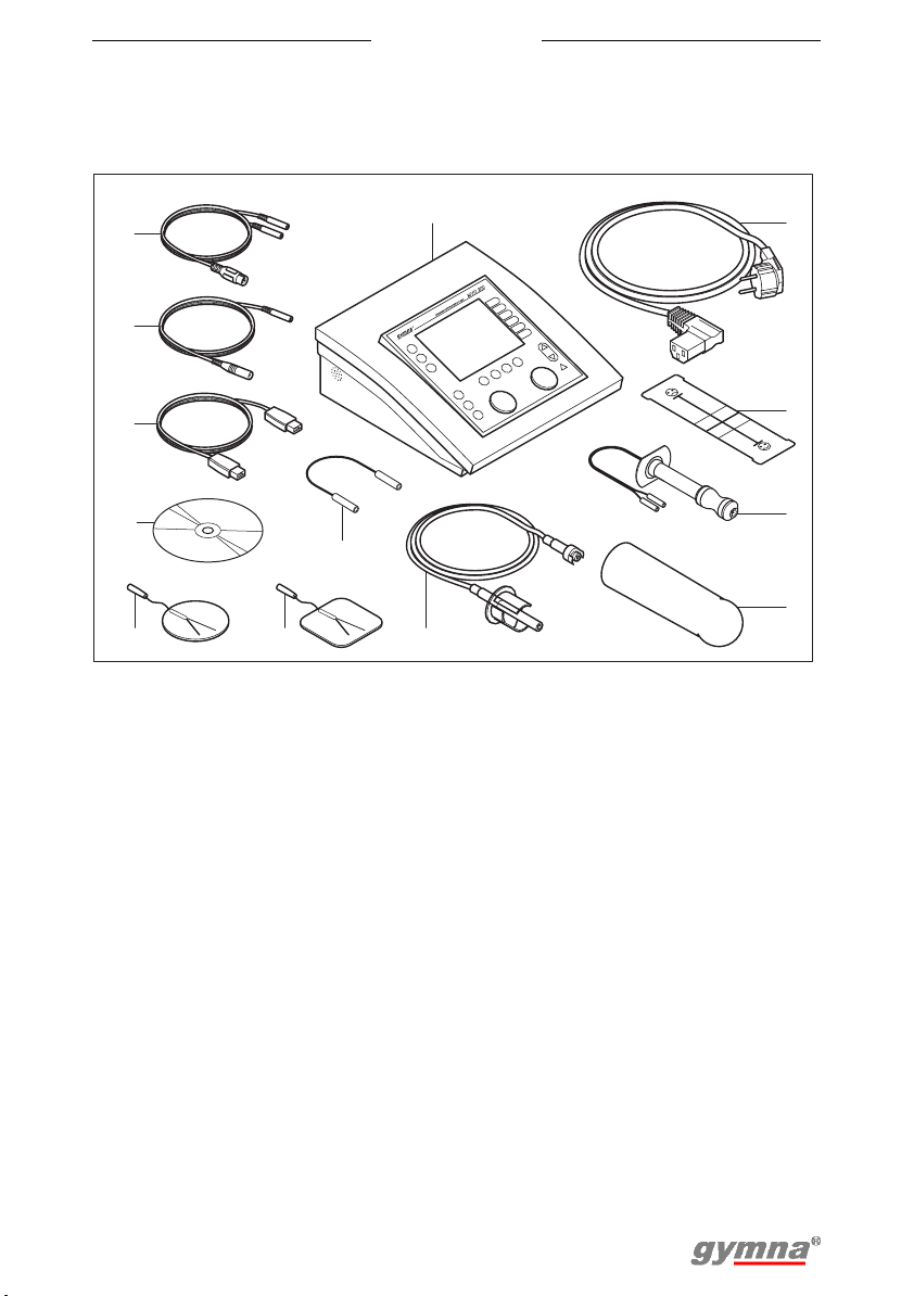
3.1 Myo 200 and standard accessories
13
12
11
10
7
9 8
1. Myo 200. See §3.2.
2. Power cord
3. VAS score card
4. Vaginal probe ‘Novatys’
5. Vaginal pressure probe
6. Vaginal pressure pipe
7. Test plug
8. Adhensive electrodes (4 pieces)
6
1
9. Adhensive electrodes round (4
pieces)
10. CD-ROM with Myo 200 PCsoftware
11. USB connection cable
12. Reference cable
13. Two-ply EMG electrode cable (2
pieces) and two-ply EMGincontinence electrode cable
2
3
4
5
13

Myo 200
3.2 Components of Myo 200
21
1
2
3
4
5
6
7
A
B
AB
8139101112
1. Display. See §3.3.1.
2. Electrotherapy stimulation
3. Feedback
4. Electrotherapy stimulation and
feedback
5. Memory
6. Start menu
7. Channel selection: A or B
8. Stop
9. Intensity of channel A
10. Pause
11. Return to previous menu
12. Intensity of channel B
13. Enter
14. Indication: Read manual
15. Down
16. Up
17. Select parameter or menu
REF
B
A
P
1918
2220 23 24
17
25 26 27 28
16
15
14
!
29 30
31
18. Connector for pressure
feedback, channel P
19. Indicator lamp for channel A
20. Connector for electrode,
channel A
21. Indication: Type BF applied part
22. Indicator lamp for channel B
23. Connector for electrode,
channel B
24. Connector for reference
electrode
25. On/off switch
26. Connection to mains supply
27. Type plate
28. Ventilation opening
29. Fuse holder
30. USB connector
31. Speaker grill
14
Myo 200
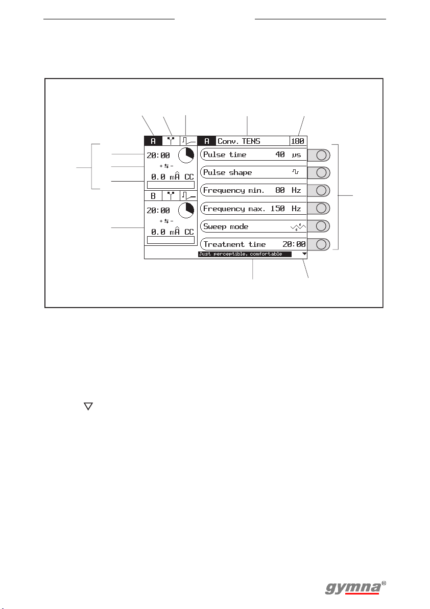
3.3 Display
3.3.1 Display for electrotherapy
123 4
10
11
9
12
13
1. Channel
2. Electrotherapy
3. Current shape
4. Title of the screen
5. Program number
6. Parameters with selection
knobs
7. Use to go to the next
parameters
15:00
set
red+
0
.
0
0
0
.
0
US+Conv
Pulse time
Pulse form
CV
Min.
Max.
Sweep mode
Treatment
Perceptibe, comfortable
5
.
TENS
frequency
frequency
time
8
8. Explanation or recommendation
9. Screen for channel A. See
§4.3.6.
10. Remaining treatment time
11. Polarity
12. Set intensity
13. Screen for channel B
40 s
80
100
15:00
34
Hz
Hz
6
7
15
Myo 200
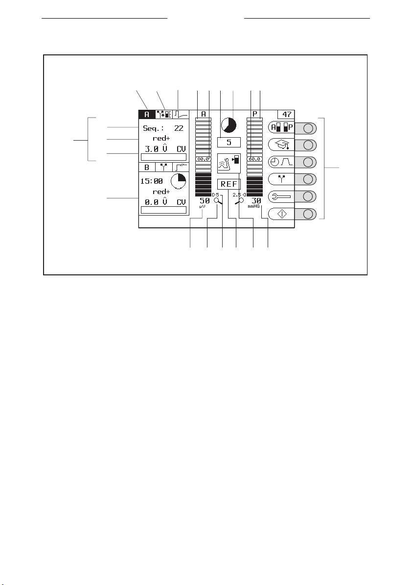
3.3.2 Display for re-education
123 7
18
17
19
20
21
16
1. Channel
2. Therapy (ET, FB or ET-FB)
3. Current shape
4. Bar graph of channel A
5. Target value of channel A
6. Remaining phase time (in
seconds)
7. Remaining phase time
(diagram)
8. Target value of channel P (B)
9. Bar graph of channel P (B)
10. Settings with selection knobs
11. Feedback value of channel P (B)
46
985
1415 12 1113
12. Phase symbol
13. Warning no reference electrode
14. Resolution, value of one bar
graph segment
15. Zoom function active
16. Feedback value of channel A
17. Screen for channel A.
18. Remaining number of
sequences or remaining
treatment time
19. Polarity
20. Set intensity
21. Screen for channel B
10
16
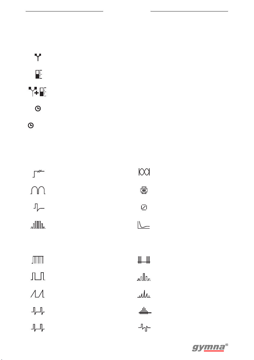
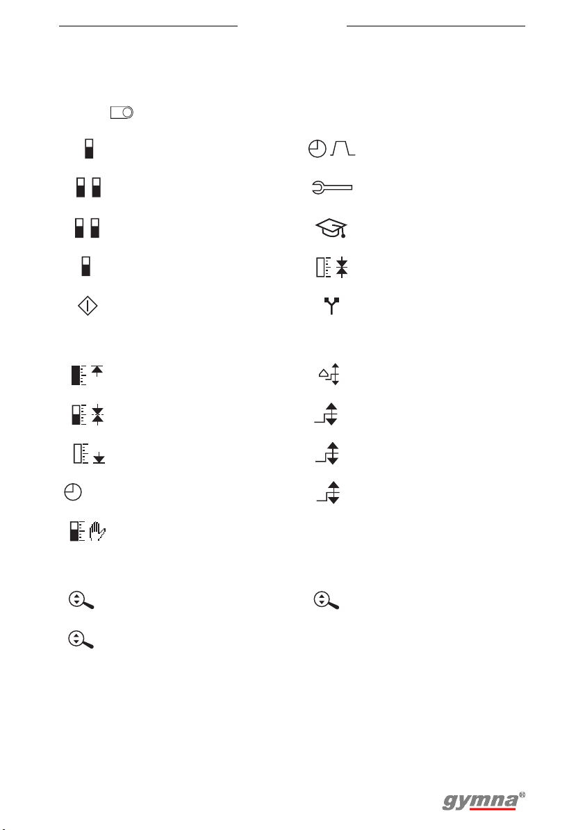
3.4 Display symbols
3.4.1 General
Myo 200
Electrotherapy
stimulation
Feedback Channel B
Electrotherapy
stimulation and feedback
Treatment time Channel P
Treatment completed ET:
0:00
3.4.2 Current shape groups
Unidirectional currents 2-pole medium frequency
Diadynamic 4-pole Interferential
TENS currents
NMES currents Diagnostic programs
A
B
A + B
P
SEQ
Channel A
Channel A and B
simultaneously
Sequential current
shapes
Number of
FB:
sequences
4-pole interferential with
vector
3.5 Symbols for current shapes in memory menu
Medium frequency
unidirectional current
Unidirectional rectangular
current
Unidirectional triangular
current
Conventional TENS Biphasic surge current
Low frequency TENS
17
Burst TENS
Rectangular surge
current
Triangular surge current
Intrapulse interval surge
current
Myo 200
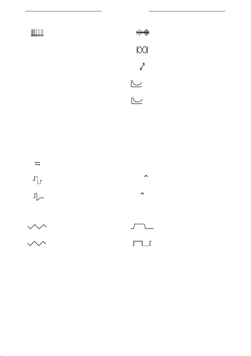
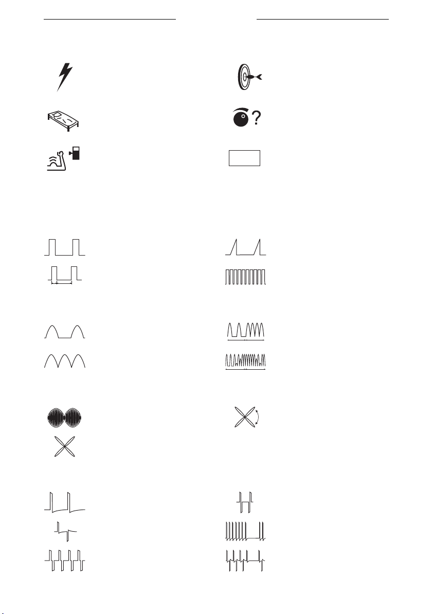
Random TENS
CP
DF
LP
MF
CP (diadynamic) 2-pole medium frequency
DF (diadynamic)
LP (diadynamic) Rheobase and chronaxie
MF (diadynamic) Rheobase and AQ
3.6 Parameter
3.6.1 Electrotherapy
Red+
Red-
+
Polarity indication Constant Current
Alternating polarity Constant Voltage
-
Biphasic pulse shape,
symmetrical
Biphasic pulse shape,
asymmetrical
CHR
AQ
CC
CV
mA
V
2-pole medium frequency
surge current
4-pole interferential with
rotating vector
mA peak
Volt peak (V
pk
)
Sweep mode
12
12
6
12s/12s 1s/5s -1s/5s
6
6s/6s 1s/1s
11
18
5
5
1
1
Myo 200
3.6.2 re-education
To maintain the overview on the re-education display, the settings symbols
disappear after a while. The settings symbols appear again by pressing on a
random .
A
A
A
Capture target
Feedback channel A Phase time menu
Feedback channel A
B
and B
Feedback channel A
P
and P (pressure)
Feedback P Capture target menu
P
Start
Maximum capture target
method
Mean capture target
method
Minimum capture target
method
Time for the automatic
s
capture target
Manual capture target
method
Myo settings menu
Expert menu
Electrotherapy
parameters menu
Step size target change
Adjust target channel A
A
Adjust target channel B
B
Adjust target channel P
P
Zoom function
Zoom channel A Zoom channel P
A
Zoom channel B
B
P
19
State symbols
Stimulation phase Capture target
z
z
z
Rest phase Stimulation assessment
Myo 200
Feedback phase
3.7 Current shapes
3.7.1 Unidirectional currents
Rectangular pulse current Triangular pulse current
2-5 current (UltraReiz)
5 ms
2 ms
3.7.2 Diadynamic currents
MF CP
DF LP
3.7.3 Interferential currents
2-pole medium frequency
4-pole Interferential
REF
MF
MF
Warning no reference
electrode
Medium frequency
rectangular current
DF
DF
4-pole interferential with
rotating vector
3.7.4 TENS currents
Conventional TENS,
asymmetrical
Conventional TENS,
alternating asymmetrical
Conventional TENS,
symmetrical
Conventional TENS,
alternating symmetrical
TENS burst
TENS burst, alternating
20
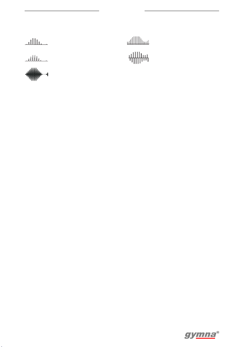
3.7.5 NMES currents
Myo 200
Rectangular surge
current
Triangular surge current
Medium frequency surge
current (2- and 4-pole)
Biphasic surge current
Intrapulse interval surge
current
21

Myo 200
22
Myo 200
4OPERATION
4.1 Therapy selection
You can select a therapy in different ways, with the therapy key or with the
parameters in the Start menu:
• Therapy keys: Quickly select a therapy with therapy keys , and .
See §4.1.1.
• Objectives: Select a therapy on the basis of an objective. See §4.1.2.
• Indication list: Select a therapy on the basis of a medical indication.
See §4.1.3.
• Program number: Select a certain program number or a program
number that you previously saved. See §4.1.4.
• Diagnostic programs: Perform a diagnosis, for example to determine
the rheobase and the chronaxie. See §4.1.5.
• Contra indications: Display an overview with contra indications for the
electrotherapy. See §4.1.6.
Besides this, you can change the system settings. See §4.8.
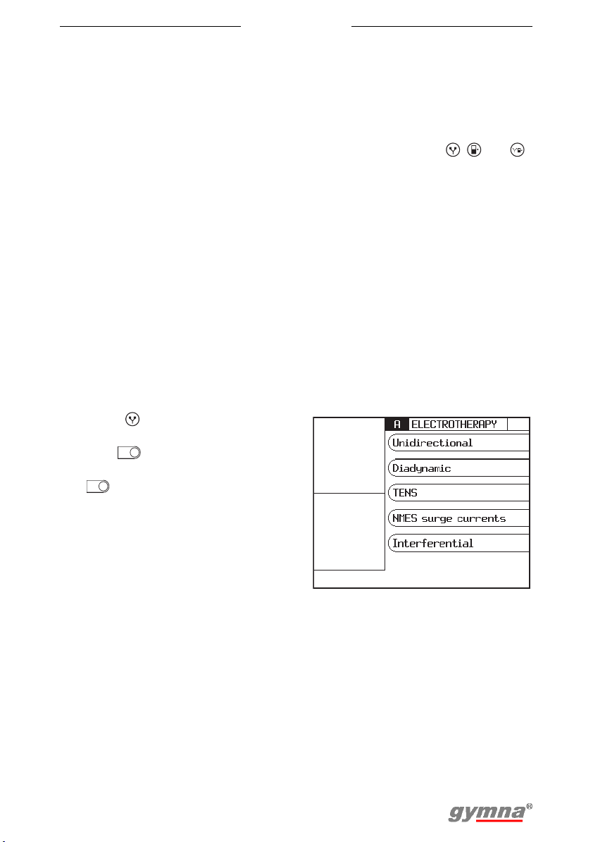
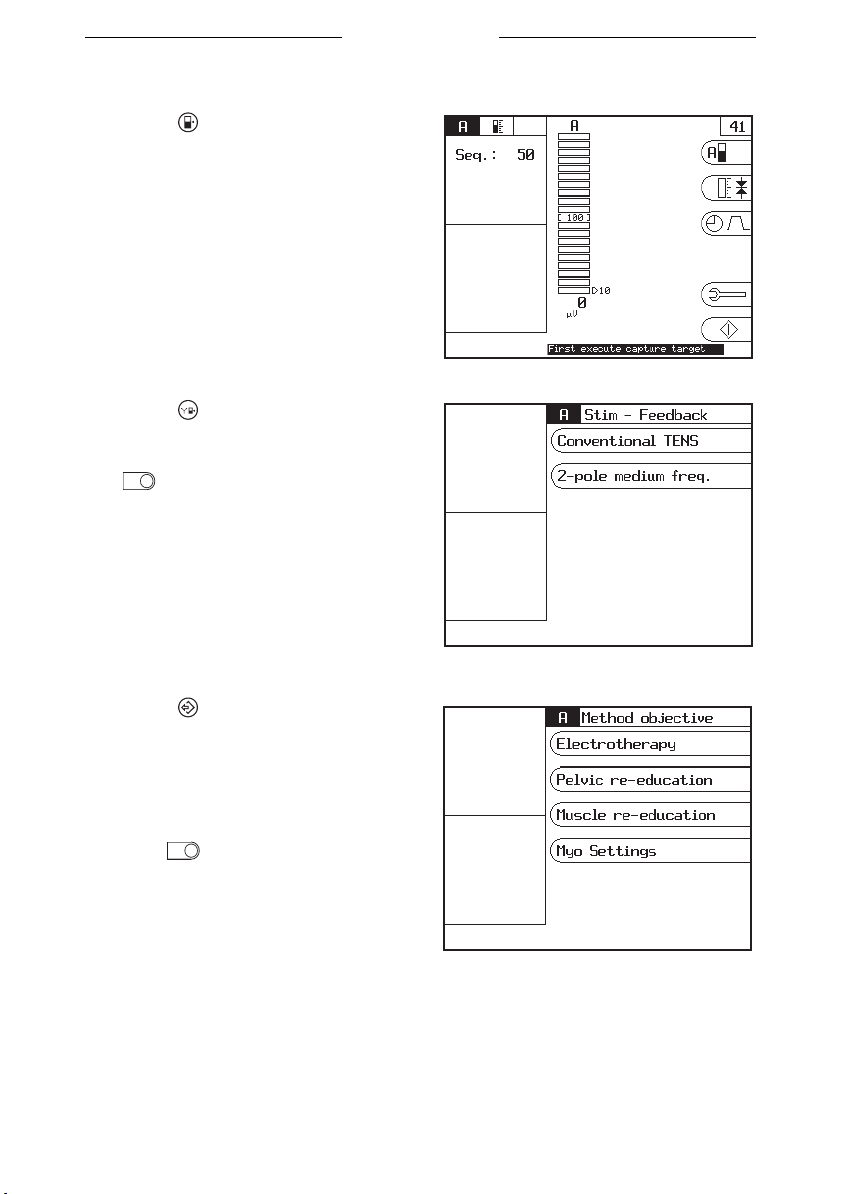
4.1.1 Therapy keys
Electrotherapy selection
1. Press : Electrotherapy.
2. Select the current shape group
with .
3. Select the current shape with
.
23
Myo 200
Feedback selection
1. Press : Feedback. The
Feedback screen appears.
Electrotherapy in combination with feedback selection
1. Press : Electrotherapy and
feedback.
2. Select the current shape with
.
4.1.2 Therapy selection via objectives
1. Press to go to the start menu.
2. Select Objectives.
3. Select Electrotherapy, Pelvic
re-education or Muscle reeducation.
4. Select the desired treatment
with .
24
Myo 200
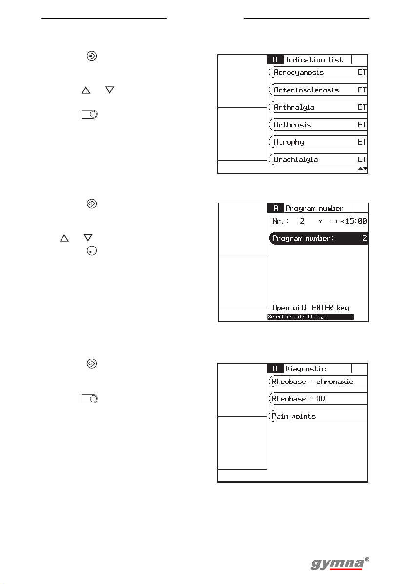
4.1.3 Therapy selection via indication list
1. Press to go to the start menu.
2. Select Indication list.
3. Go to the following indications
with or . See §9.1.4.
4. Select the desired indication
with .
• ET: Electrotherapy
4.1.4 Program number selection
1. Press to go to the start menu.
2. Select Program number.
3. Select the desired program with
or . See §9.1.
4. Press . See §4.7.
4.1.5 Diagnostic program selection
With the diagnostic programs, you can localise and treat pain points, etc.
1. Press to go to the start menu.
2. Select Diagnostic programs.
3. Select the desired diagnosis
with . See §4.6.
25

Myo 200
4.1.6 Contra indication selection
1. Press to go to the start menu.
2. Select Contra indications.
3. Select the therapy for which you
want to see the contra
indications.
4.2 Performing therapy
4.2.1 Channel settings
The Myo 200 has the possibility to select a therapy individual or in
combination. The following channel settings are possible.
Channel A Channel B Channel P
ET - - §4.3.1 and §4.3.2
-ET-§4.3.1 and §4.3.2
ET ET - §4.3.1, §4.3.2 and §4.3.5
FB - - §4.4.1
- - FB (pressure) §4.4.2
FB FB - §4.4.1 and §4.4.3
FB - FB (pressure) §4.4.1, §4.4.2 and §4.4.3
FB ET - §4.4.1, §4.3.1 and §4.3.2
FB ET FB (pressure) §4.4.1, §4.3.1, §4.3.2,
§4.4.2 and §4.4.3
ET+FB - - §4.5.1
ET+FB FB - §4.5.1, §4.4.1, §4.4.3 and
ET+FB - FB (pressure) §4.5.1, §4.4.2, §4.4.3 and
ET+FB ET+FB - §4.5.1 and §4.5.3
See
§4.5.3
§4.5.3
26
Myo 200
Channel A Channel B Channel P
See
ET+FB ET - §4.5.1, §4.3.1, §4.3.2 and
§4.5.3
ET+FB ET FB (pressure) §4.5.1, §4.3.1, §4.3.2,
§4.5.3, §4.4.2 and §4.4.3
4.2.2 Set parameters
1. Select the desired parameters with after the therapy is selected.
See §4.1. You can only change the outlined parameters. In the reeducation display the small outlined parameters disappear during
treatment after a while to keep the overview on the screen. Press a
random first to see the parameters.
2. Change the value of the parameter with and . The setting range of
the parameter is shown at the bottom of the screen. You can change
the parameter as long as the parameter has a black background.
4.2.3 Temporary interruption of treatment
1. If the other channel has to pause: Select this channel with .
2. Press during the treatment. The treatment time of the selected
channel is stopped. Pause appears on the screen. The parameter
settings are retained.
3. Press on again to restart the treatment. The intensity now increases
gradually to the set level and the treatment time continues again.
A
B
4.2.4 Immediately stop treatment
1. Press . All active treatments are stopped immediately. Stop appears
on the screen. The parameter settings are retained.
2. Set the intensity of the channel again to continue the treatment.
4.3 Electrotherapy
4.3.1 Performing electrotherapy with electrodes
1. Select the desired electrotherapy program. See §4.1.
2. Place the electrodes. See page 28: Placing rubber electrodes and page
28: Placing adhesive electrodes. With some treatments, the Electrode
placing parameter refers to the number in the placing diagrams.
3. Rotate intensity knob A or B to start the electrotherapy and to set the
desired intensity. See §4.1.2.
4. Check the patient's reaction. Repeat this check regularly during the
treatment.
5. The equipment stops the treatment and indicates that the treatment is
completed. Remove the electrodes.
27
Myo 200
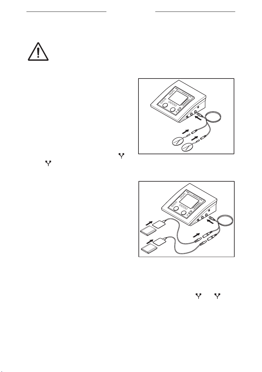
Placing adhesive electrodes
Do not use adhesive electrodes with currents that have a
galvanic component, such as galvanic, diadynamic, MF
rectangular, pulsed rectangular and triangular currents.
These currents can cause skin etching.
1. If possible, disinfect the parts of
the body where the adhesive
electrodes are to be placed.
2. Place the electrodes on the part of
the body that must be treated.
3. Connect the connectors of the
adhesive electrodes to the two-ply
EMG electrode cable (black and
red connector).
4. Connect the two-ply EMG
electrode cable to connector
or of the Myo 200.
B
A
Placing rubber electrodes
1. Moisten two EL sponges. Use
water with a saline solution to
improve the conductivity of the EL
sponges.
2. Slide a rubber electrode into each
sponge.
3. Place the sponges on the part of
the body that must be treated.
4. Fasten the sponges to the part of
the body with the elastic fixation
straps.
5. Connect the red connector of the rubber electrode to the red connector
of the two-ply (EMG) electrode cable (4 mm).
6. Connect the black connector of the rubber electrode to the black
connector of the two-ply (EMG) electrode cable (4 mm).
7. Connect the two-ply (EMG) electrode cable to connector or of
A
B
the Myo 200.
28
Myo 200
4.3.2 Performing electrotherapy with a probe
• Considering the hygiene and the very personal and intimate
character of these treatments, a probe may only be used for
one patient.
• Never disinfect the probes in an autoclave. The probes can be
damaged by the extreme temperature.
1. Clean the probe carefully with soap and water. See §5.2.4.
2. Select the desired electrotherapy program.
3. Make sure the intensity is zero.
4. Place the probe. See page 29: Placing a vaginal or an anal probe and
page 30: Placing a rectal probe.
5. Rotate intensity knob A or B to start the treatment and to set the
desired intensity.
6. Check the patient's reaction. Repeat this check regularly during the
treatment.
7. The equipment stops the treatment and indicates that the treatment is
completed.
8. Make sure the intensity is zero.
9. Remove the probe.
10. Clean the probe. See §5.2.4.
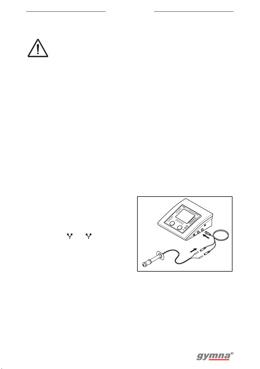
Placing a vaginal or an anal probe
1. Connect the probe to the two-ply
EMG-incontinence electrode cable
(white connectors).
2. Connect the two-ply EMGincontinence electrode cable to
connector or of the Myo
200. The probe is immediately
detected by the equipment. To
prevent unpleasant stimulations,
you can only set alternating
currents with a Constant Voltage
(CV) setting, such as TENS, NMES, and 2-pole interferential currents.
3. Apply, if necessary, an antiseptic lubricant to the probe.
4. Place the probe.
A
B
29
 Loading...