

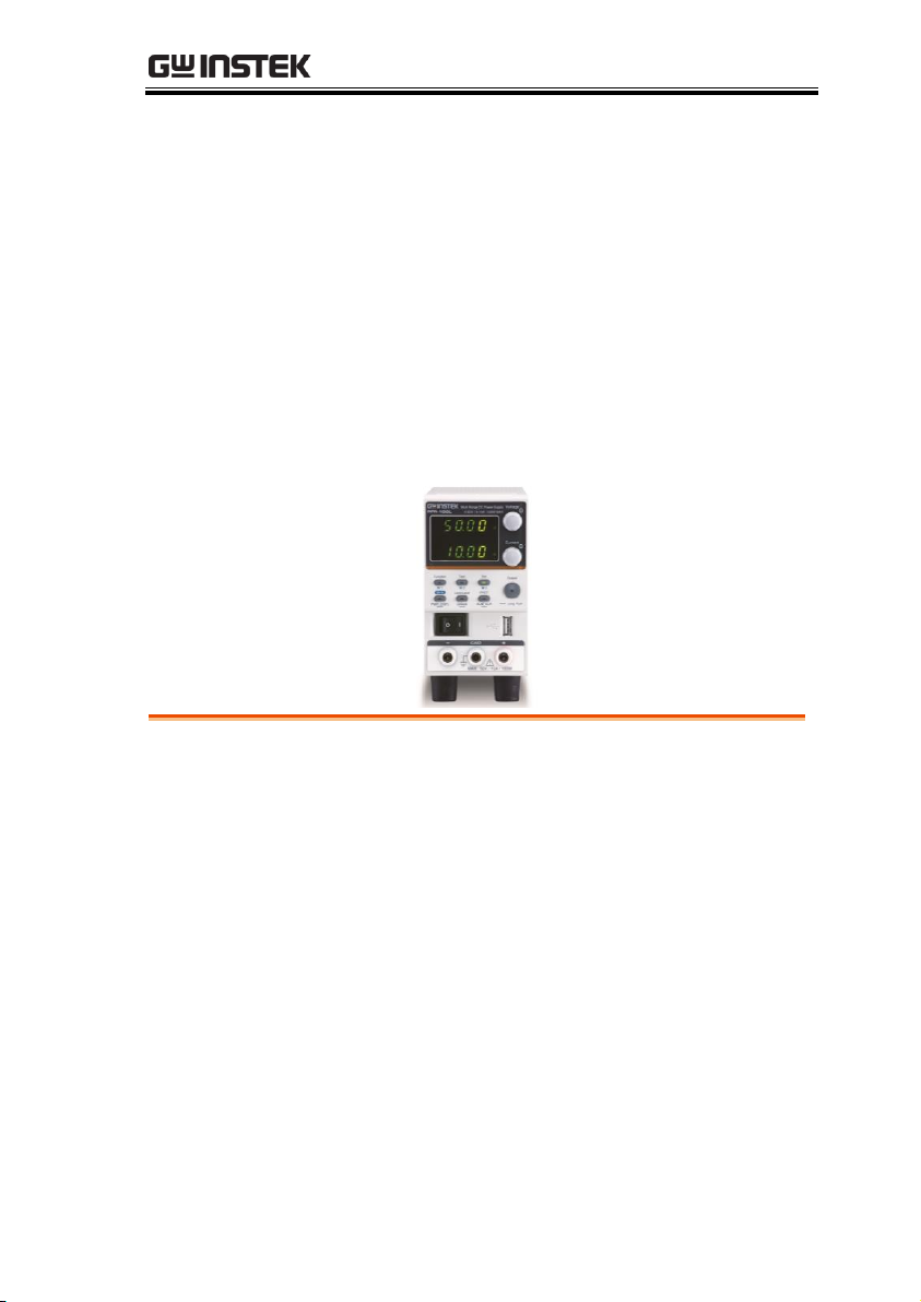
Multi-Range DC Power Supply
PFR-100 Series
USER MANUAL
ISO-9001 CERTIFIED MANUFACTURER
99 Washington Street
Melrose, MA 02176
Phone 781-665-1400
Toll Free 1-800-517-8431
Visit us at www.TestEquipmentDepot.com

This manual contains proprietary information, which is protected by
copyright. All rights are reserved. No part of this manual may be
photocopied, reproduced or translated to another language without
prior written consent of Good Will company.
The information in this manual was correct at the time of printing.
However, Good Will continues to improve products and reserves the
rights to change specification, equipment, and maintenance
procedures at any time without notice.

TABLE OF CONTENTS
Table of Contents
SAFETY INSTRUCTIONS ................................................... 5
GETTING STARTED ........................................................... 9
PFR-100 Series Overview ...................... 10
Appearance .......................................... 13
Theory of Operation ............................. 20
OPERATION .................................................................... 32
Set Up .................................................. 33
Basic Operation ................................... 44
Test Scripts .......................................... 58
CONFIGURATION ........................................................... 66
Configuration Overview ....................... 67
ANALOG CONTROL ........................................................ 83
Analog Remote Control Overview ......... 84
Remote Monitoring ............................ 102
COMMUNICATION INTERFACE ..................................... 107
Interface Configuration ...................... 108
FAQ ............................................................................... 139
APPENDIX ................................................................
PFR-100 Factory Default Settings ....... 141
Error Messages & Messages .............. 143
LED ASCII Table Character Set ........... 144
PFR-100 Specifications....................... 145
PFR-100 Dimensions .......................... 151
Declaration of Conformity .................. 152
..... 141
3

PFR-100 Series User Manual
INDEX ............................................................................ 153
4
SAFETY INSTRUCTIONS
WARNING
Warning: Identifies conditions or practices that
could result in injury or loss of life.
CAUTION
Caution: Identifies conditions or practices that
could result in damage to the PFR-100 or to other
properties.
DANGER High Voltage
Attention Refer to the Manual
Protective Conductor Terminal
Earth (ground) Terminal
SAFETY INSTRUCTIONS
This chapter contains important safety
instructions that you must follow during
operation and storage. Read the following before
any operation to insure your safety and to keep
the instrument in the best possible condition.
Safety Symbols
These safety symbols may appear in this manual or on the
instrument.
5
Do not dispose electronic equipment as unsorted
municipal waste. Please use a separate collection
facility or contact the supplier from which this
instrument was purchased.
Safety Guidelines
General
Guideline
CAUTION
Do not place any heavy object on the PFR-100.
Avoid severe impact or rough handling that
leads to damaging the PFR-100.
Do not discharge static electricity to the PFR-
100.
Use only mating connectors, not bare wires, for
the terminals.
Do not disassemble the PFR-100 unless you are
qualified.
Power Supply
WARNING
AC Input Voltage: 100Vac-240Vac
Frequency: 47Hz to 63Hz
To avoid electrical shock connect the protective
grounding conductor of the AC power cord to
an earth ground.
Cleaning the PFR100
Disconnect the power cord before cleaning.
Use a soft cloth dampened in a solution of mild
detergent and water. Do not spray any liquid.
Do not use chemicals containing harsh material
such as benzene, toluene, xylene, and acetone.
Operation
Environment
Location: Indoor, no direct sunlight, dust free,
almost non-conductive pollution (Note below)
Relative Humidity: 20%~ 80% (no condensation)
Altitude: < 2000m
Temperature: 0°C to 40°C
PFR-100 Series User Manual
6
SAFETY INSTRUCTIONS
(Pollution Degree) EN61010-1:2010 specifies the pollution degrees
and their requirements as follows. The PFR-100 falls under degree 2.
Pollution refers to “addition of foreign matter, solid, liquid, or
gaseous (ionized gases), that may produce a reduction of dielectric
strength or surface resistivity”.
Pollution degree 1: No pollution or only dry, non-conductive
pollution occurs. The pollution has no influence.
Pollution degree 2: Normally only non-conductive pollution
occurs. Occasionally, however, a temporary conductivity caused
by condensation must be expected.
Pollution degree 3: Conductive pollution occurs, or dry, non-
conductive pollution occurs which becomes conductive due to
condensation which is expected. In such conditions, equipment
is normally protected against exposure to direct sunlight,
precipitation, and full wind pressure, but neither temperature
nor humidity is controlled.
Storage
environment
Location: Indoor
Temperature: -20°C to 70°C
Relative Humidity: 20 to 85%(no condensation)
Disposal
Do not dispose this instrument as unsorted
municipal waste. Please use a separate collection
facility or contact the supplier from which this
instrument was purchased. Please make sure
discarded electrical waste is properly recycled to
reduce environmental impact.
7
PFR-100 Series User Manual
Green/ Yellow:
Earth
Blue:
Neutral
Brown:
Live (Phase)
Power cord for
the United Kingdom
When using the power supply in the United Kingdom, make sure
the power cord meets the following safety instructions.
NOTE: This lead/appliance must only be wired by competent persons
WARNING: THIS APPLIANCE MUST BE EARTHED
IMPORTANT: The wires in this lead are coloured in accordance with the
following code:
As the colours of the wires in main leads may not correspond with
the coloured marking identified in your plug/appliance, proceed
as follows:
The wire which is coloured Green & Yellow must be connected to
the Earth terminal marked with either the letter E, the earth symbol
or coloured Green/Green & Yellow.
The wire which is coloured Blue must be connected to the terminal
which is marked with the letter N or coloured Blue or Black.
The wire which is coloured Brown must be connected to the
terminal marked with the letter L or P or coloured Brown or Red.
If in doubt, consult the instructions provided with the equipment
or contact the supplier.
This cable/appliance should be protected by a suitably rated and
approved HBC mains fuse: refer to the rating information on the
equipment and/or user instructions for details. As a guide, a cable
of 0.75mm2 should be protected by a 3A or 5A fuse. Larger
conductors would normally require 13A types, depending on the
connection method used.
Any exposed wiring from a cable, plug or connection that is
engaged in a live socket is extremely hazardous. If a cable or plug is
deemed hazardous, turn off the mains power and remove the cable,
any fuses and fuse assemblies. All hazardous wiring must be
immediately destroyed and replaced in accordance to the above
standard.
8
GETTING STARTED
PFR-100 Series Overview ......................................... 10
Series lineup ................................................................................... 10
Main Features................................................................................. 10
Accessories ..................................................................................... 11
Appearance .............................................................. 13
Front Panel ..................................................................................... 13
Display Area ................................................................................... 16
Rear Panel ....................................................................................... 18
Theory of Operation ................................................ 20
Operating Area Description ........................................................ 20
CC and CV Mode .......................................................................... 22
Slew Rate ........................................................................................ 23
Bleeder Control ............................................................................. 24
Sink Current Table ........................................................................ 25
Alarms ............................................................................................. 26
Considerations ............................................................................... 27
Grounding ...................................................................................... 30
This chapter describes the power supply in a
nutshell, including its main features and front /
rear panel introduction. After going through the
overview, please read the theory of operation to
become familiar with the operating modes,
protection modes and other safety considerations.
GETTING STARTED
9

PFR-100 Series User Manual
Model name
Operation Voltage
Operation Current
Rated Power
PFR-100L
0-50V
0-10A
100W
PFR-100M
0-250V
0-2A
100W
Performance
Variable voltage and current combinations with
5 times of coverage ratio of its range within the
rated power.
Constant voltage/constant current with
automatic crossover.
Active Power Factor correction.
Universal Input Voltage 85 - 265Vac, continuous
operation.
Natural convection cooling.
Features
Preset memory function.
Output ON/OFF delay function.
CV, CC priority start function. (prevents
overshoot with output ON)
Adjustable voltage and current slew rates.
Bleeder circuit ON/OFF setting. (to prevent
over-discharging of batteries)
OVP, OCP, AC FAIL, OPP and OTP protection.
Supports test scripts.
PFR-100 Series Overview
Series lineup
The PFR-100 series consists of 2 models, covering a number of
different current, voltage and power capacities:
Main Features
10

GETTING STARTED
Web server monitoring and control. (The
function is activated when connecting to LAN
Interface)
Analog monitor output.
Remote sensing to compensate for voltage drop
in load leads.
Built-in front panel and rear panel output
terminal.
Interface
Built-in USB and RS-232/485 interface.
External analog control function.
Optional LAN and GPIB interface.
Standard
Accessories
Part number
Description
Qty.
CD-ROM
User manual, Programming manual
1
Power Cord
1
GTL-134
Test leads for rear panel, 1.2m, 10A,
16AWG
1
PFR-001
Binding Posts Terminal Accessory Kit
(Output terminal cover × 1, Socket ×
1, Protection Cover × 2, Short Bar × 1)
1
GTL-104A
Test leads for PFR-100L (Binding
Posts Terminal), 1m, 10A
1
PFR-002
European Type Jack Terminal
Accessory Kit (Output terminal cover
× 1, Socket × 1, Protection Cover × 2,
Short Wire × 1)
1
GTL-105A
Test leads for PFR-100M, 1m, 3A
1
GTL-204A
Test leads for PFR-100L (European
Type Jack Terminal), 1m, 10A
1
Accessories
Before using the PFR-100 power supply unit, check the package
contents to make sure all the standard accessories are included.
11

PFR-100 Series User Manual
Optional
Accessories
Part number
Description
GRA-431-J-100
Rack mount adapter (JIS) with AC 100V
GRA-431-J-200
Rack mount adapter (JIS) with AC 200V
GRA-431-E-100
Rack mount adapter (EIA) with AC 100V
GRA-431-E-200
Rack mount adapter (EIA) with AC 200V
GTL-258
GPIB Cable, 2000mm
PSU-232
RS-232 Cable with DB9 Connector Kit. It
includes RS-232 cable with DB9 connector,
RS-485 used master cable (gray plug), slave
cable (black plug) and end plug terminal.
PSU-485
RS-485 Cable with DB9 Connector Kit. It
includes RS-485 cable with DB9 connector,
RS-485 used master cable (gray plug), slave
cable (black plug) and end plug terminal.
GTL-246
USB Cable (USB 2.0 Type A- Type B Cable,
4P)
Factory Installed
Options
Part number
Description
PFR-GL
LAN + GPIB interface
12
Appearance
A
W
V
W
RUNM3M2M1LANERR
ISR
C C
DLY
ALM
RMT
C V
VSR
Function Set
Output
PROTLock/Local
Shift
Voltage
Current
PFR-100L
0-50V / 0-10A 100W MAX
Multi-Range DC Power Supply
M 1
Test
M 2 M 3
ALM_CLRUnlock
PWR_DSPL
: Long Push
GND
MAX. 50V / 10A / 100W
2
Display Area
1
5
9
8
11
12
3
4
6
7
10
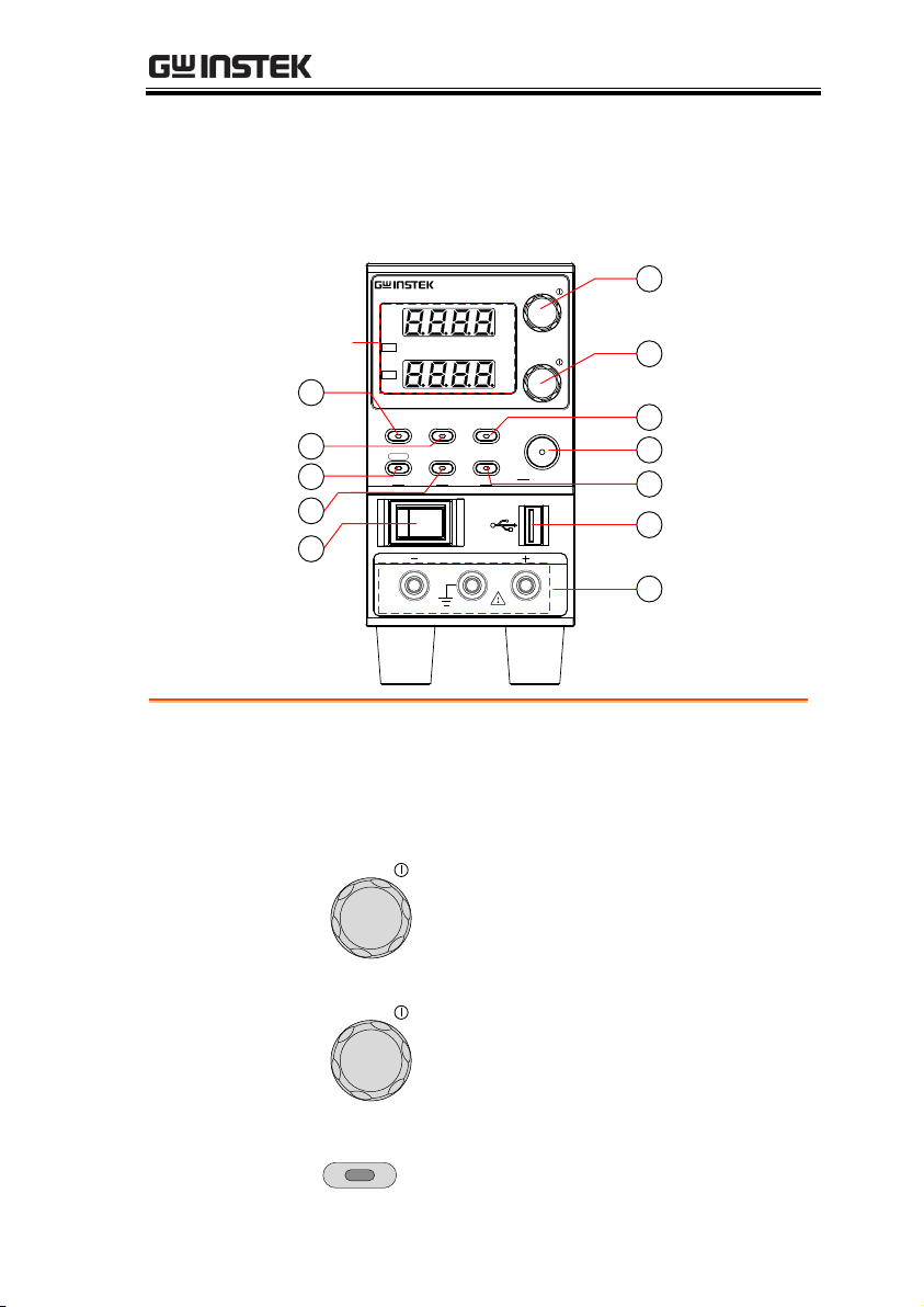
Display Area
The display area shows setting values, output
values and parameter settings. The function LEDs
below show the current status and mode of the
power supply. See page 16 for details.
1.
Voltage Knob
Voltage
Used to set the voltage value or select
a parameter number in the Function
settings.
2.
Current Knob
Current
Used to set the current value or
change the value of a Function
parameter.
3.
Function
Button
Function
M1
Used to configure the various
functions.
Front Panel
GETTING STARTED
13

PFR-100 Series User Manual
M1 Button
(+Shift) Used to recall the M1 setup.
(+Shift and hold) Used to save the
current setup to M1.
4.
Test Button
TEST
M2
Used to run customized scripts for
testing.
M2 Button
(+Shift) Used to recall the M2 setup.
(+Shift and hold) Used to save the
current setup to M2.
5.
Set Button
SET
M3
Used to set and confirm the output
voltage and output current.
M3 Button
(+Shift) Used to recall the M3 setup.
(+Shift and hold) Used to save the
current setup to M3.
6.
Shift Button
Shift
PWR_DSPL
Used to enable the functions that are
written in blue characters below
certain buttons.
PWR_DSPL
(Long push) Displays the output
power on the voltage meter or current
meter. Press the Voltage knob for
V/W, Press the Current knob for
A/W.
7.
Lock/Local
Button
Lock/Local
Unlock
Used to lock all front panel buttons
other than the Output Button or it
switches to local mode.
Unlock
Button
(Long push) Used to unlock the front
panel buttons.
14
GETTING STARTED
8.
PROT Button
PROT
ALM_CLR
Used to set and display OVP, OCP
and UVL.
ALM_CLR
Button
(Long push) Used to release
protection functions that have been
activated.
9.
Output
Button
Output
Used to turn the output on or off.
10.
Power Switch
Used to turn the power on/off.
11.
USB A Port
USB A port for data transfer, loading
test scripts etc.
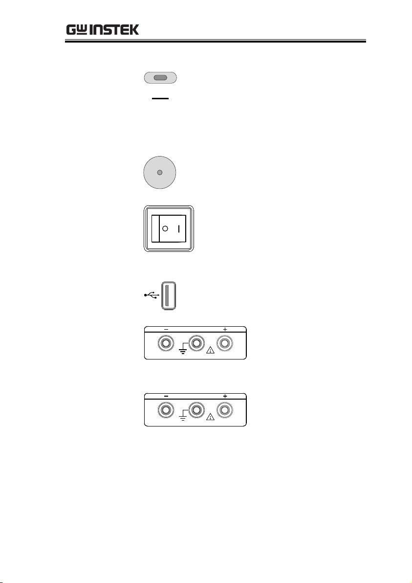
12
Output
terminal
GND
MAX. 250V / 2A / 100W
DC output terminal for PFR100M is European Type Jack
Terminal.
The max. output is
250V/2A/100W
GND
MAX. 50V / 10A / 100W
DC output terminal for PFR100L is Binding Posts
Terminal or European Type
Jack Terminal.
The max. output is
50V/10A/100W
15

PFR-100 Series User Manual
A
W
V
W
RUNM3M2M1LANERR
ISR
C C
DLY
ALM
RMT
C V
VSR
13
14
15
16
17
18
19
20 21 22 23 24
25
26
27
28
29
13.
VSR LED
Lights up when CV Slew Rate Priority is
enabled.
14.
CV LED
Lights in green during constant voltage mode.
15.
RMT LED
Lights in green during remote control.
16.
ALM LED
Lights in red when a protection function has
been activated.
17.
DLY LED
The Output On/Off Delay indicator LED.
18.
CC LED
Lights in green during constant current mode.
19.
ISR LED
Lights up when CC Slew Rate Priority is
enabled.
20.
ERR LED
Lights in red when an error has occurred.
21.
LAN LED
Lights up when the LAN remote connection is
established.
22.
M1 LED
Lights in green when the memory value are
being recalled or saved.
Display Area
16

GETTING STARTED
23.
M2 LED
Lights in green when the memory value are
being recalled or saved.
24.
M3 LED
Lights in green when the memory value are
being recalled or saved.
25.
V or W LED
Display Voltage or Watt unit.
26.
RUN LED
Lights up when a Test Script has been
activated.
27.
A or W LED
Display Current or Watt unit.
28.
Voltage Meter
Displays the voltage or the parameter number
of a Function parameter.
29.
Current Meter
Displays the current or the value of a Function
parameter.
17
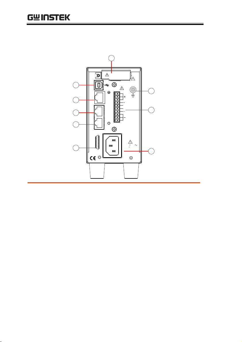
Rear Panel
V
S
N.C.
RS232
/ RS485
IN
OUT
100 240V
47 63Hz
150VA MAX.
AC
J1
S
N.C.
V
LAN
GPIB
protection cover
Analog control
1
2
3
4
5
6
7
8
9
1.
USB
USB port for controlling the PFR-100 remotely.
2.
LAN
Ethernet port for controlling the PFR-100
remotely (Factory Installed Options).
3.
Remote-OUT
RJ-45 connector that is used to daisy chain power
supplies with the Remote-IN port to form a
communication bus.
4.
Remote-IN
Two different types of cables can be used for
RS232 or RS485-based remote control.
PSU-232: RS232 cable with DB9 connector kit.
PSU-485: RS485 cable with DB9 connector kit.
5.
GPIB
GPIB connector for units equipped with IEEE
programming option. (Factory Installed Options)
PFR-100 Series User Manual
18

GETTING STARTED
6.
J1
External analog remote control connector.
7.
Ground
Screw
Connectors for grounding the output.
8.
Output
Terminals
It uses a 10 pin connector and a plug for the
output and sense terminal connections.
9
Line Voltage
Input
AC inlet.
19
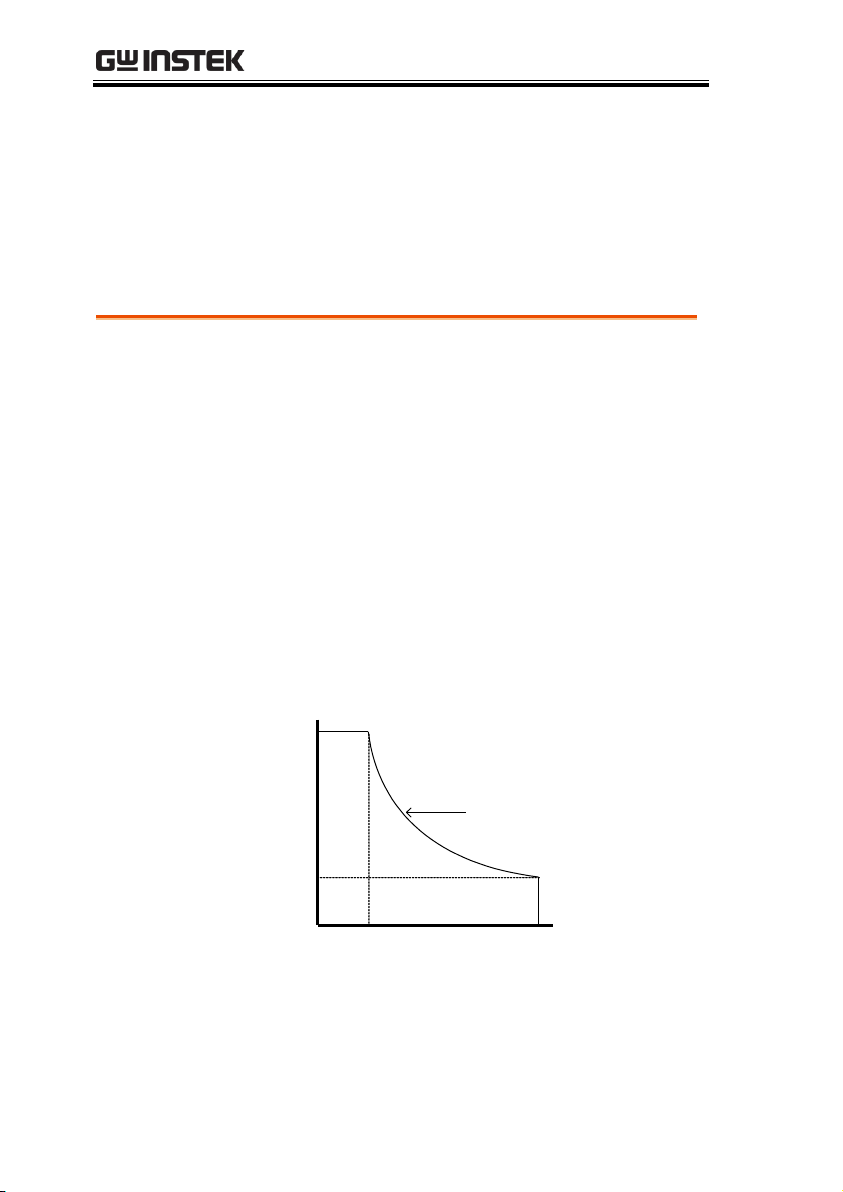
Background
The PFR-100 power supplies are regulated DC
power supplies with a high voltage and current
output. These operate in CC or CV mode
within a wide operating range limited only by
the voltage or current output.
The operating area of each power supply is
determined by the rated output power as well
as the voltage and current rating.
For example the operating area and rated
power output for the PFR-100L is shown
below.
50
100W rated power
10
2 10
PFR-100L Operating Area
Current (A)
Voltage (V)
When the power supply is configured so that
the total output (current x voltage output) is
less than the rated power output, the power
supply functions as a typical constant current,
PFR-100 Series User Manual
Theory of Operation
The theory of operation chapter describes the basic principles of
operation, protection modes and important considerations that
must be taken into account before use.
Operating Area Description
20
GETTING STARTED
constant voltage power supply.
If however, the power supply is configured
such that the total output (current x voltage
output) exceeds the rated power output, the
effective output is actually limited to the power
limit of the unit. In this case the output current
and voltage then depend purely on the load
value.
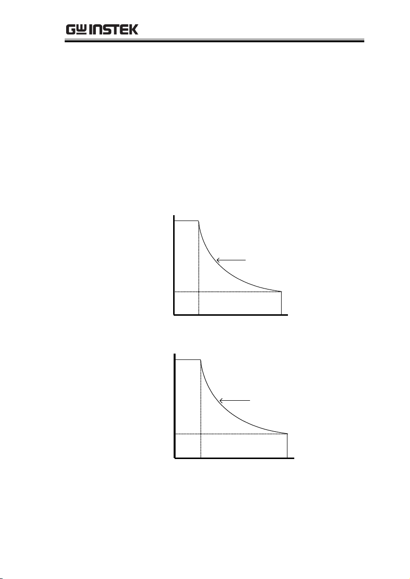
Below is a comparison of the operating areas of
each power supply.
50
100W rated power
10
2 10
PFR-100L Operating Area
Current (A)
Voltage (V)
250
100W rated power
50
0.4 2
PFR-100M Operating Area
Current (A)
Voltage (V)
21

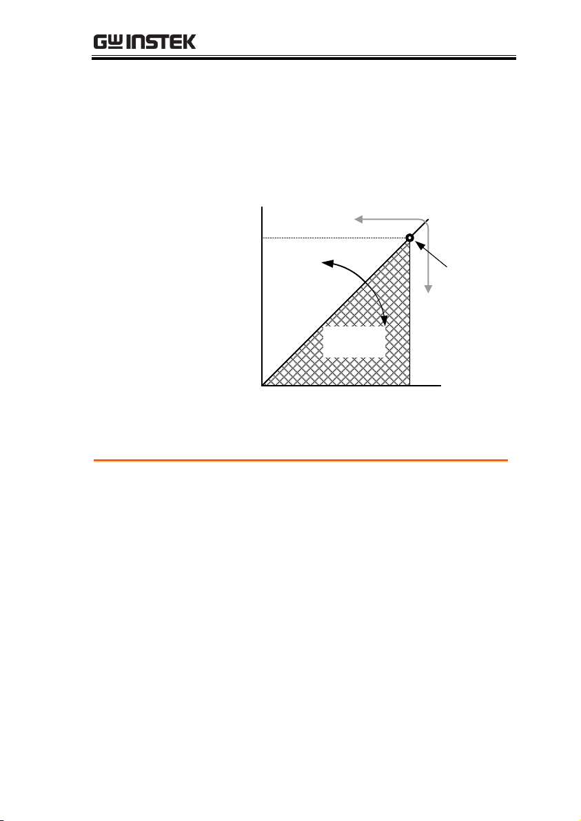
CC and CV Mode
CC and CV mode
Description
When the power supply is operating in
constant current mode (CC) a constant current
will be supplied to the load. When in constant
current mode the voltage output can vary,
whilst the current remains constant. When the
load resistance increases to the point where the
set current limit (I
SET
) can no longer be
sustained the power supply switches to CV
mode. The point where the power supply
switches modes is the crossover point.
When the power supply is operating in CV
mode, a constant voltage will be supplied to
the load, whilst the current will vary as the
load varies. At the point that the load
resistance is too low to maintain a constant
voltage, the power supply will switch to CC
mode and maintain the set current limit.
The conditions that determine whether the
power supply operates in CC or CV (V
SET
), the
load resistance (RL) and the critical resistance
(RC). The critical resistance is determined by
V
SET/ISET
. The power supply will operate in CV
mode when the load resistance is greater than
the critical resistance. This means that the
voltage output will be equal to the V
SET
voltage
but the current will be less than I
SET
. If the load
resistance is reduced to the point that the
current output reaches the I
SET
level, the power
supply switches to CC mode.
PFR-100 Series User Manual
22
GETTING STARTED
Conversely the power supply will operate in
CC mode when the load resistance is less than
the critical resistance. In CC mode the current
output is equal to I
SET
and the voltage output is
less than V
SET
.
RL=R
C
RL<R
C
VSET
ISET
CV
CC
V
I
RL>R
C
Crossover
point
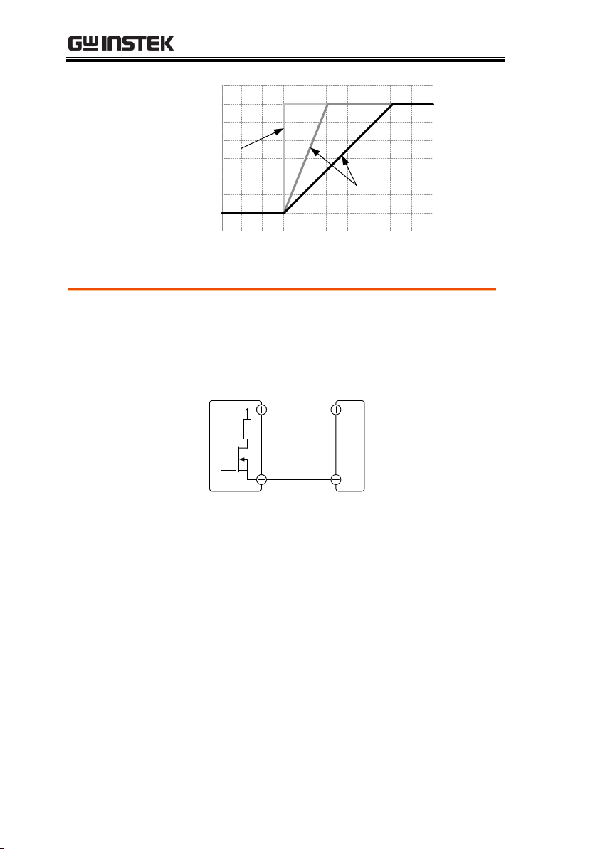
Theory
The PFR-100 has selectable slew rates for CC
and CV mode. This gives the PFR-100 power
supply the ability to limit the current/voltage
draw of the power supply. Slew rate settings
are divided into High Speed Priority and Slew
Rate Priority. High speed priority mode will
use the fastest slew rate for the instrument.
Slew Rate Priority mode allows for user
adjustable slew rates for CC or CV mode. The
rising and falling slew rate can be set
independently.
Slew Rate
23
High Speed
Priority
mode
Slew rate =
Enabled
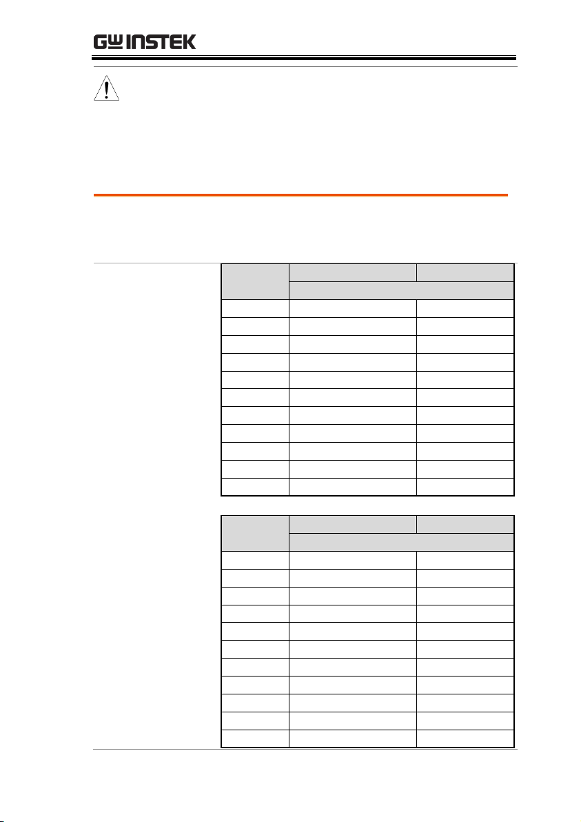
Bleeder Control
Background
The PFR-100 DC power supplies employ a
bleed resistor in parallel with the output
terminals.
PFR-100
Load
Bleed
resistor
Bleed resistors are designed to dissipate the
power from the power supply filter capacitors
when power is turned off and the load is
disconnected. Without a bleed resistor, power
may remain charged on the filter capacitors for
some time and be potentially hazardous.
In addition, bleed resistors also allow for
smoother voltage regulation of the power
supply as the bleed resistor acts as a minimum
voltage load.
The bleed resistance can be turned on or off
using the configuration settings.
PFR-100 Series User Manual
24
Note
By default the bleed resistance is on. For battery
charging applications, be sure to turn the bleed
resistance off as the bleed resistor can discharge
the connected battery when the unit is off.
Sink Current Table
Background
Sink current (reference value) from an external
voltage source according to the bleeder circuit
setting.
PFR-100M
Vout
Bleeder ON
Bleeder OFF
Sink Current
(V)
(A)
(mA)
25
0.135
0.001
50
0.119
0.007
75
0.103
0.014
100
0.087
0.022
125
0.071
0.032
150
0.055
0.034
175
0.039
0.043
200
0.034
0.051
225
0.031
0.067
250
0.028
0.086
PFR-100L
Vout
Bleeder ON
Bleeder OFF
Sink Current
(V)
(A)
(mA)
5
0.746
0.006
10
0.658
0.009
15
0.570
0.013
20
0.482
0.017
25
0.375
0.026
30
0.310
0.038
35
0.257
0.038
40
0.236
0.048
45
0.218
0.074
50
0.200
0.200
GETTING STARTED
25

PFR-100 Series User Manual
OVP
Over voltage protection (OVP) prevents a high
voltage from damaging the load. This alarm
can be set by the user.
OCP
Over current protection prevents high current
from damaging the load. This alarm can be set
by the user.
OPP
Over power protection prevents abnormally
use from damaging the PFR-100.
When the output power is over 103W, the
alarm signal will be lit and start to counter.
After a little time, OPP will be triggered and
turn off output.
UVL
Under voltage limit. This function sets a
minimum voltage setting level for the output.
It can be set by the user.
OHP
Over temperature protection protect the
instrument from overheating
AC
AC Fail. This alarm function is activated when
a low AC input is detected.
SENSE ALARM1
This alarm function is activated when real
output voltage is larger than sense output
voltage.
Vo_real > Vo_sense + 1.5V for PFR-100L
Vo_real > Vo_sense + 2.5V for PFR-100M
Alarms
The PFR-100 power supplies have a number of protection features.
When one of the protection alarms is set, the ALM icon on the
display will be lit.
please see page 44.
For details on how to set the protection modes,
26

GETTING STARTED
SENSE ALARM2
This alarm function is activated when sense
output voltage is larger than real output
voltage.
Vo_sense > Vo_real + 1V
Shutdown
Force Shutdown is not activated as a result of
the PFR-100 series detecting an error. It is a
function that is used to turn the output off
through the application of a signal from the
rear-panel analog control connector when an
abnormal condition occurs.
Alarm output
Alarms are output via the analog control
connector. The alarm output is an isolated
open-collector photo coupler output.
Inrush current
When the power supply switch is first turned
on, an inrush current is generated. Ensure there
is enough power available for the power
supply when first turned on, especially if a
number of units are turned on at the same
time.
Caution
Cycling the power on and off quickly can cause the
inrush current limiting circuit to fail as well as
reduce the working life of the input fuse and power
switch.
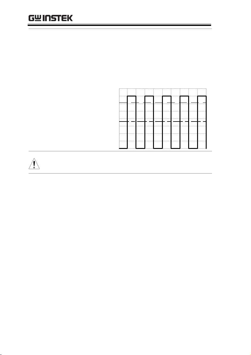
Pulsed or Peaked
loads
When the load has current peaks or is pulsed, it
is possible for the maximum current to exceed
the mean current value. The PFR-100 power
supply ammeter only indicates mean current
values, which means for pulsed current loads,
Considerations
The following situations should be taken into consideration when
using the power supply.
27
PFR-100 Series User Manual
the actual current can exceed the indicated
value. For pulsed loads, the current limit must
be increased, or a power supply with a greater
capacity must be chosen. As shown below, a
pulsed load may exceed the current limit and
the indicated current on the power supply
ammeter.
Current limit
level
Measured
Ammeter
current
Note
The LED message showed on the display will vary
depending on the F-17 setting.
Reverse Current:
Regenerative load
When the power supply is connected to a
regenerative load such as a transformer or
inverter, reverse current will feed back to the
power supply. The PFR-100 power supply
cannot absorb reverse current. For loads that
create reverse current, connect a resistor in
parallel (dummy load) to the power supply to
bypass the reverse current. To calculate the
resistance for the dummy resistor, RD, first
determine the maximum reverse current, IR,
and determine what the output voltage, EO,
will be.
28
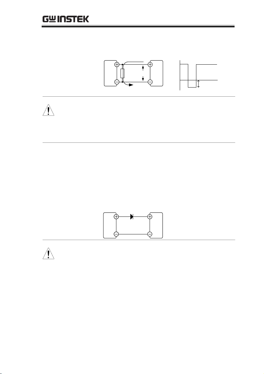
GETTING STARTED
RD(Ω) ≤ EO(V) ÷ IR(A)
PFR-100
Load
R
D
I
R
I
R
-
+
E
O
Output
Current
Note
The current output will decrease by the amount of
current absorbed by the resistor.
Ensure the resistor used can withstand the power
capacity of the power supply/load.
Reverse Current:
Accumulative
energy.
When the power supply is connected to a load
such as a battery, reverse current may flow
back to the power supply. To prevent damage
to the power supply, use a reverse-currentprotection diode in series between the power
supply and load.
PFR-100
Load
Diode
CAUTION
Ensure the reverse withstand voltage of the diode
is able to withstand 2 times the rated output
voltage of the power supply and the forward
current capacity can withstand 3 to 10 times the
rated output current of the power supply.
Ensure the diode is able to withstand the heat
generated in the following scenarios.
When the diode is used to limit reverse voltage,
remote sensing cannot be used.
29
PFR-100 Series User Manual
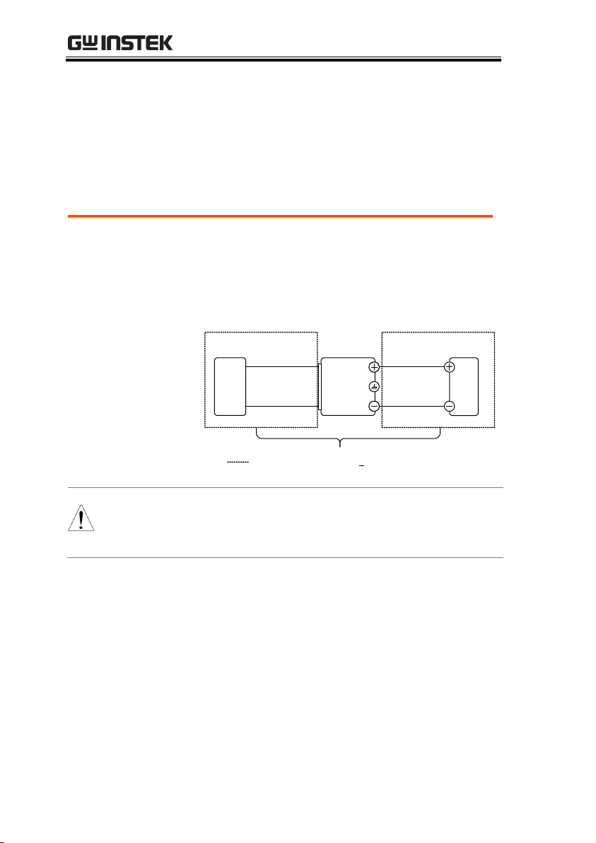
Floating
As the output terminals are floating, the load
and all load cables must have an insulation
capacity that is greater than the isolation
voltage of the power supply.
PFR-100
Load
Ext-V
Ext-R
Analog
connector
( ) Insulation capacity > isolation voltage
of power supply
WARNING
If the insulation capacity of the load and load
cables are not greater than the isolation voltage of
the power supply, electric shock may occur.
Grounding
The output terminals of the PFR-100 power supplies are isolated
with respect to the protective grounding terminal. The insulation
capacity of the load, the load cables and other connected devices
must be taken into consideration when connected to the protective
ground or when floating.
30
 Loading...