


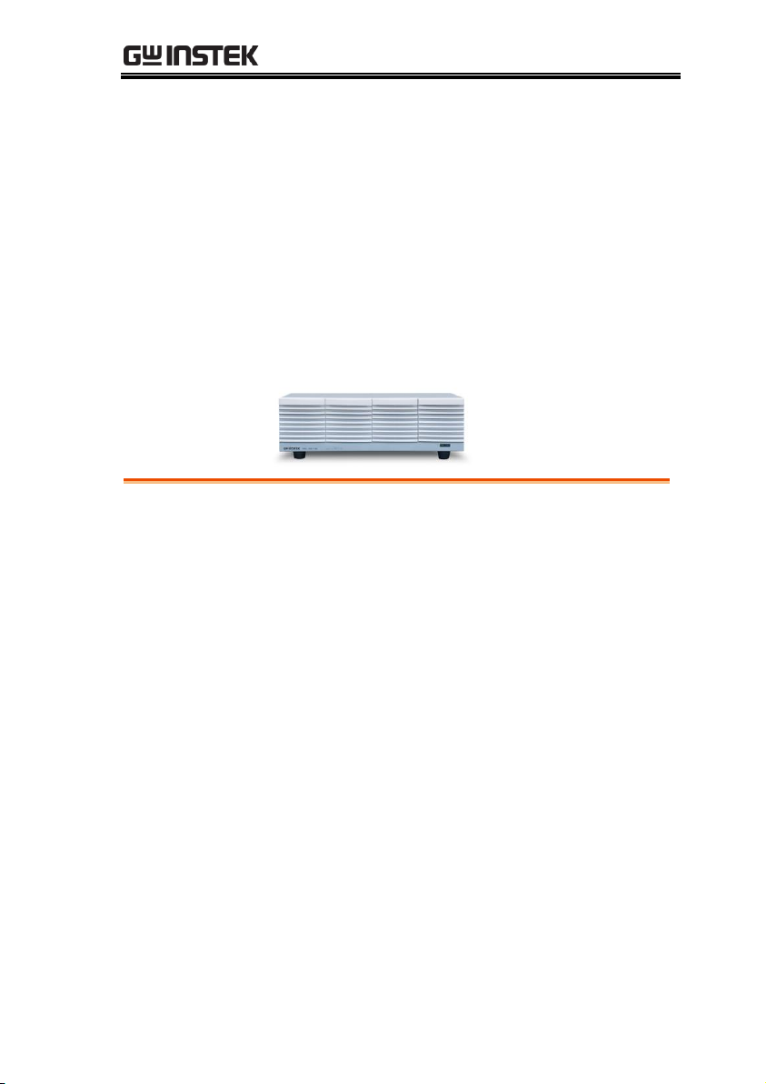
DC Electronic Load Booster
PEL-3211(H)
USER MANUAL
VERSION: 1.15
ISO-9001 CERTIFIED MANUFACTURER

This manual contains proprietary information, which is protected by
copyright. All rights are reserved. No part of this manual may be
photocopied, reproduced or translated to another language without
prior written consent of Good Will company.
The information in this manual was correct at the time of printing.
However, Good Will continues to improve products and reserves the
rights to change specification, equipment, and maintenance
procedures at any time without notice.
Good Will Instrument Co., Ltd.
No. 7-1, Jhongsing Rd., Tucheng Dist., New Taipei City 236, Taiwan.

Table of Contents
Table of Contents
SAFETY INSTRUCTIONS .................................................. 2
GETTING STARTED .......................................................... 7
PEL-3211(H) Booster Pack Introduction 8
Accessories .......................................... 10
Appearance .......................................... 13
First Time Use Instructions ................. 16
OPERATION .................................................................. 27
Connection .......................................... 28
Operation ............................................ 33
MAINTENANCE ............................................................. 35
Replacing the Dust Filter ..................... 35
APPENDIX ..................................................................... 36
Frame Control Connector Contacts ...... 36
Operating Area .................................... 38
PEL-3211(H) Booster Pack
Specifications ...................................... 40
Dimensions ......................................... 41
Declaration of Conformity .................... 42
INDEX ........................................................................... 44
1
PEL-3211(H) User Manual
WARNING
Warning: Identifies conditions or practices that
could result in injury or loss of life.
CAUTION
Caution: Identifies conditions or practices that
could result in damage to the instrument or to
other properties.
DANGER High Voltage
Attention Refer to the Manual
Earth (ground) Terminal
Frame or Chassis Terminal
Do not dispose electronic equipment as unsorted
municipal waste. Please use a separate collection
facility or contact the supplier from which this
instrument was purchased.
SAFETY INSTRUCTIONS
This chapter contains important safety
instructions that you must follow during
operation and storage. Read the following before
any operation to insure your safety and to keep
the instrument in the best possible condition.
Safety Symbols
These safety symbols may appear in this manual or on the
instrument.
2

SAFETY INSTRUCTIONS
General
Guideline
CAUTION
Do not place any heavy object on the
instrument. Note: Only two booster units can be
stacked vertically.
Avoid severe impact or rough handling that
leads to damaging the instrument.
Do not discharge static electricity to the
instrument.
Use only crimped wires, not bare wires, for the
terminals.
Do not block the cooling fan opening.
Do not disassemble the instrument unless you
are qualified.
The equipment is not for measurements
performed for CAT II, III and IV.
(Measurement categories) EN 61010-1:2010 specifies the
measurement categories and their requirements as follows. The
instrument falls under category II.
Measurement category IV is for measurement
performed at the source of low-voltage
installation.
Measurement category III is for measurement
performed in the building installation.
Measurement category II is for measurement
performed on the circuits directly connected to
the low voltage installation.
0 is for measurements performed on circuits not
directly connected to Mains.
Safety Guidelines
3

PEL-3211(H) User Manual
Power Supply
WARNING
AC Input voltage range: 100-120VAC/200-
240VAC
(90-132VAC/180-250VAC)
Frequency: 47-63Hz
Power:
PEL-3211(H): 230VA Max
To avoid electrical shock connect the protective
grounding conductor of the AC power cord to
an earth ground.
Cleaning
Disconnect the power cord before cleaning.
Use a soft cloth dampened in a solution of mild
detergent and water. Do not spray any liquid.
Do not use chemicals containing harsh material
such as benzene, toluene, xylene, and acetone.
Operation
Environment
Location: Indoor, no direct sunlight, dust free,
almost non-conductive pollution (Note below)
Temperature: 0°C to 40°C
Humidity: 0 to 85% RH
Altitude: <2000m
4
SAFETY INSTRUCTIONS
(Pollution Degree) EN 61010-1:2010 specifies the pollution degrees
and their requirements as follows. The instrument falls under
degree 2.
Pollution refers to “addition of foreign matter, solid, liquid, or
gaseous (ionized gases), that may produce a reduction of dielectric
strength or surface resistivity”.
Pollution degree 1: No pollution or only dry,
non-conductive pollution occurs. The pollution
has no influence.
Pollution degree 2: Normally only non-
conductive pollution occurs. Occasionally,
however, a temporary conductivity caused by
condensation must be expected.
Pollution degree 3: Conductive pollution occurs,
or dry, non-conductive pollution occurs which
becomes conductive due to condensation which
is expected. In such conditions, equipment is
normally protected against exposure to direct
sunlight, precipitation, and full wind pressure,
but neither temperature nor humidity is
controlled.
Storage
environment
Location: Indoor
Temperature: -20°C to 70°C
Humidity: <90% RH
Disposal
Do not dispose this instrument as unsorted
municipal waste. Please use a separate collection
facility or contact the supplier from which this
instrument was purchased. Please make sure
discarded electrical waste is properly recycled to
reduce environmental impact.
5
PEL-3211(H) User Manual
Green/ Yellow:
Earth
Blue:
Neutral
Brown:
Live (Phase)
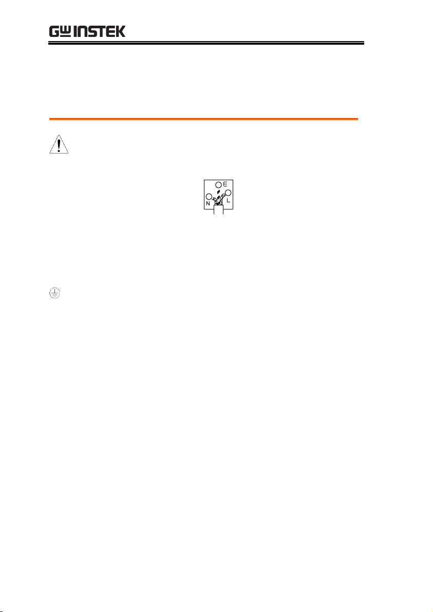
Power cord for the United Kingdom
When using the instrument in the United Kingdom, make sure the
power cord meets the following safety instructions.
NOTE: This lead/appliance must only be wired by competent persons
WARNING: THIS APPLIANCE MUST BE EARTHED
IMPORTANT: The wires in this lead are coloured in accordance with the
following code:
As the colours of the wires in main leads may not correspond with
the coloured marking identified in your plug/appliance, proceed
as follows:
The wire which is coloured Green & Yellow must be connected to
the Earth terminal marked with either the letter E, the earth symbol
or coloured Green/Green & Yellow.
The wire which is coloured Blue must be connected to the terminal
which is marked with the letter N or coloured Blue or Black.
The wire which is coloured Brown must be connected to the
terminal marked with the letter L or P or coloured Brown or Red.
If in doubt, consult the instructions provided with the equipment
or contact the supplier.
This cable/appliance should be protected by a suitably rated and
approved HBC mains fuse: refer to the rating information on the
equipment and/or user instructions for details. As a guide, a cable
of 0.75mm2 should be protected by a 3A or 5A fuse. Larger
conductors would normally require 13A types, depending on the
connection method used.
Any exposed wiring from a cable, plug or connection that is
engaged in a live socket is extremely hazardous. If a cable or plug is
deemed hazardous, turn off the mains power and remove the cable,
any fuses and fuse assemblies. All hazardous wiring must be
immediately destroyed and replaced in accordance to the above
standard.
6
GETTING STARTED
PEL-3211(H) Booster Pack Introduction ...................... 8
Booster Capacity ....................................................................................... 8
Main Features ............................................................................................ 9
Accessories ................................................................ 10
Package Contents ................................................................................... 12
Appearance ................................................................ 13
Front Panel .............................................................................................. 13
Rear Panel ................................................................................................ 14
First Time Use Instructions ....................................... 16
Rack Mount Kits .................................................................................... 16
Power Up ................................................................................................. 18
Load Wiring ............................................................................................. 18
Using the Rear Panel Input Terminals ............................................... 21
Using the Terminal Cover (PEL-011) ................................................ 22
Using the Terminal Cover (PEL-013) ................................................ 25
GETTING STARTED
This chapter provides a brief overview of the
PEL-3211, the package contents, instructions for
first time use and an introduction to the front
panel and rear panel.
7

PEL-3211(H) User Manual
No. of
Boosters
Total Current:
Boosters+Master
(PEL-3211(H)+PEL-3111(H))
Total Power:
Boosters+Master
(PEL-3211(H)+PEL-3111(H))
1
630A (420A+210A)
(H)157.5A(105A+52.5A)
3150W (2100W+1050W)
2
1050A (840A+210A)
(H)262.5A(210A+52.5A)
5250W (4200W+1050W)
3
1470A (1260A+210A)
(H)367.5A(315A+52.5A)
7350W (6300W+1050W)
4
1890A (1680A+210A)
(H)472.5A(420A+52.5A)
9450W (8400W+1050W)
PEL-3211(H) Booster Pack Introduction
The PEL-3211(H) Booster is designed to be used with the PEL3111(H) Electronic Load for parallel load applications to increase
the current sinking capacity. Up to 4 booster packs can be
connected as slave units to a PEL-3111(H), which acts as the master
unit.
Please note that throughout this manual the term “PEL-3000(H)”
refers to any one of the models in the series lineup, unless
specifically stated otherwise. The termer “booster” refers only to
the PEL-3211(H). The term “master” or “master unit” refers to the
PEL-3111(H) unit that is configured as the master unit when in
parallel mode.
Booster Capacity
The table below shows the total current and power capacity by the
number of booster packs connected to a PEL-3111(H) master unit.
8

Main Features
Features
Up to 4 booster packs can be used in parallel
with a PEL-3111(H) master unit.
All booster packs are controlled via a master
unit.
GETTING STARTED
9
PEL-3211(H) User Manual
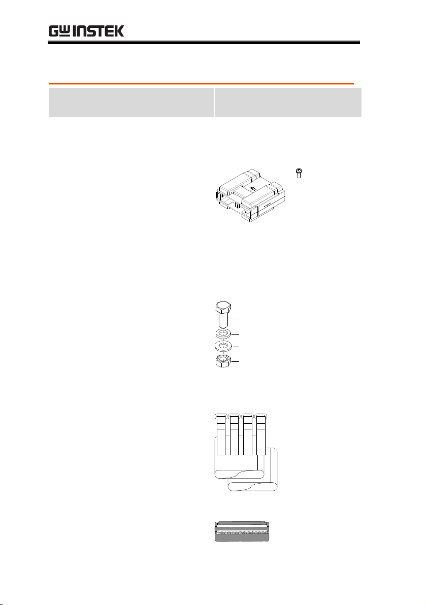
Standard
Accessories
Part number
Description
Booster Quick Start Guide
Region dependant
Power cord
PEL-011
Load input terminal Cover
M3
screw
PEL-012
Terminal fittings: 2 sets of
bolts/nuts/springs/washers (type:
M8), Terminal Cover x1 (only for
PEL-3000H series), Monitor Out
Cover x 1(only for PEL-3021H,
PEL-3041H, PEL-3111H)
M8 x 20
Spring washer
Flat washer
M8 nut
PEL-013
Flexible terminal cover: 2x rubber
sheeting, 4x Velcro fasteners.
(For PEL-3211(H) only)
Velcro
fasteners x4
Rubber
sheeting x2
PEL-014
J1/J2 Protection plug x2 (It is
installed on the device)
Accessories
10

GETTING STARTED
GTL-255
300mm Frame Link Cable (for
linking units that are stacked)
Optional
Accessories
Part number
Description
GRA-413
Rack mount bracket for booster
PEL-3211(H) (EIA + JIS)
PEL-010
Dust Filter
11
PEL-3211(H) User Manual
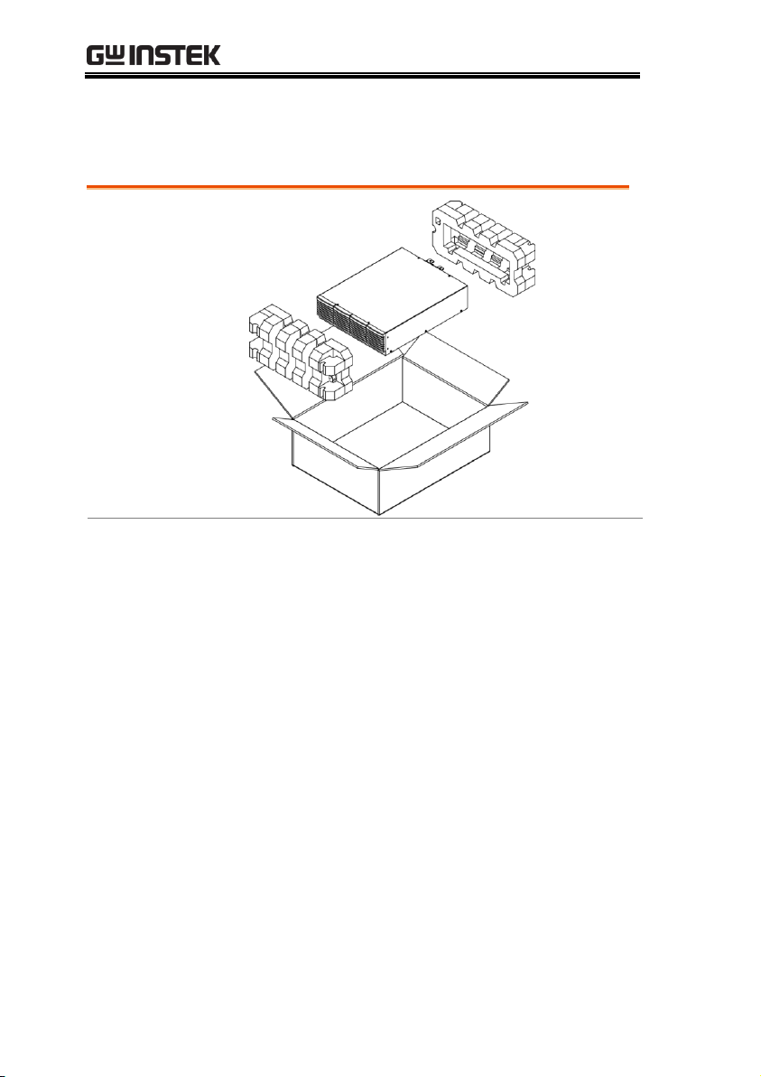
Opening the box
Contents
(single unit)
Main unit
Booster Quick Start
manual
Terminal fittings
Power cord x1 (region
dependent)
Calibration certificate
Frame link cable
Package Contents
Check the contents before using the instrument.
12
 Loading...