How it Works
Log In / Sign Up
Buy Points
How it Works
FAQ
Contact Us
Questions and Suggestions
Users
GW Instek
Loading...
L
LCR-914
LCR-914 Series
LCR-915 Series
LCR-916
LCR-916 Series
M
MDO-2000AG Series
MDO-2000A Series
MDO-2072EX
MDO-2102A
MDO-2102AG
MDO-2104EX
2
MDO-2202A
2
MDO-2202AG
MDO-2302A
MDO-2302AG
MFG-2000
MFG-2000 Series
2
MFG-2110
3
MFG-2120
3
MFG-2120MA
3
MFG-2130M
4
MFG-2160MF
2
MFG-2160MR
2
MFG-2220HM
2
MFG-2230M
3
MFG-2260M
3
MFG-2260MFA
2
MFG-2260MRA
2
MSO-2000E
MSO-2000EA
MSO-2072E
P
PCS-1000
PCS-1000I
PEL-2000
2
PEL-2000A Series
2
PEL-2000 Series
2
PEL-2002
2
PEL-2002A
2
PEL-2004
2
PEL-2004A
2
PEL-2020A
2
PEL-2041A
PEL-300
PEL-3000
3
PEL-3000E
PEL-3000H Series
3
PEL-3000 Series
5
PEL-3021
4
PEL-3021H
2
PEL-3031E
PEL-3032E
PEL-3041
4
PEL-3041H
2
PEL-3111
5
PEL-3111H
3
PEL-3211
7
PEL-3211H
5
PFR-100L
2
PFR-100M
2
PFR-100 Series
2
PHX 1000-12
PHX 1000-6
PHX 30-200
PHX 30-400
PHX 500-12
PHX 500-24
PHX 60-100
PHX 60-200
PLR-20-18
3
PLR 20-36
PLR 36-10
PLR 36-20
PLR 60-12
PLR 60-6
PLR Series
PPH-1503
PPH-1503D
PPH-1506D
PPH-1510D
PPX Series
PSB-1000 series
PSB-1400L
3
PSB-1400M
2
PSB-1800L
2
PSB-1800M
2
PSB-2000
2
PSB-2000 series
PSB-2800L
2
PSH-10100A
PSH-1036A
PSH-1070A
PSH-2018A
PSH-2035A
PSH-2050A
PSH-3610A
2
PSH-3620A
2
PSH-3630A
2
PSH-6006A
PSH-6012A
PSH SERIES
2
Loading...
Loading...
Nothing found
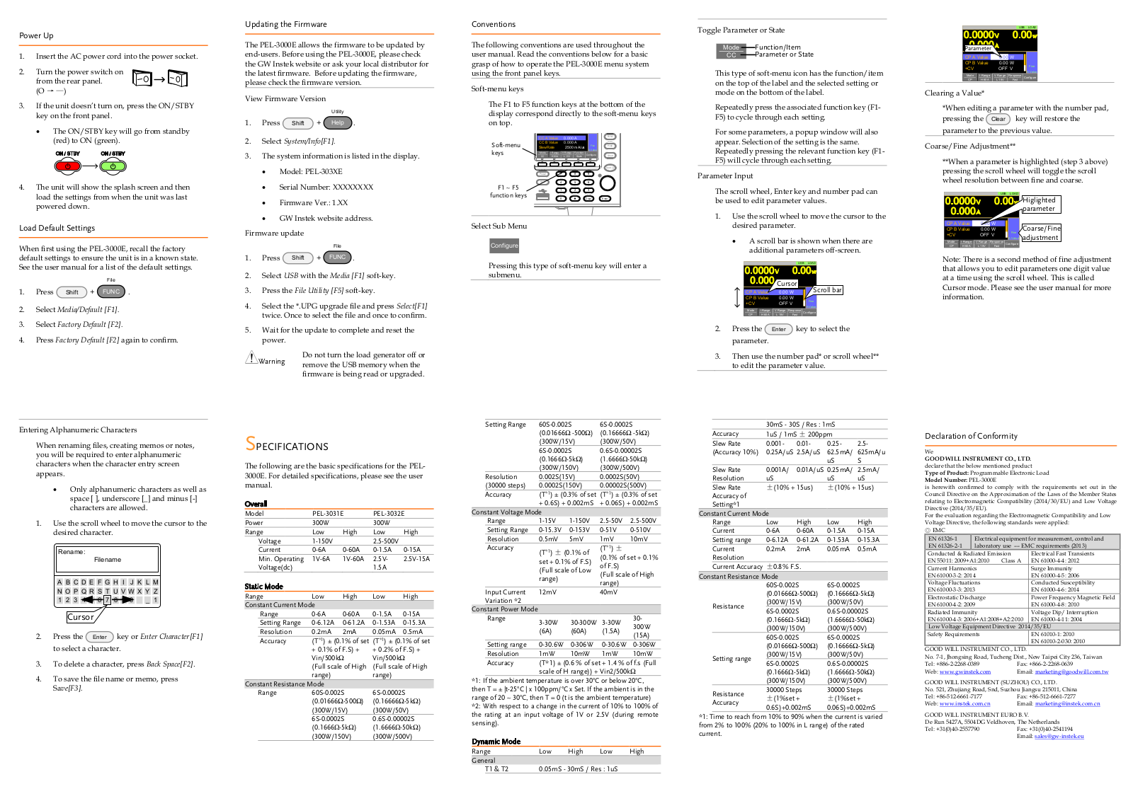
PEL-3032E
User guide
2 pgs
1.05 Mb
0
Table of contents
Loading...
GW Instek PEL-3032E User guide
...
GW Instek User guide
Download
Specifications and Main Features
Frequently Asked Questions
User Manual
Download
Loading...
+
hidden pages
Unhide
You need points to download manuals.
1 point = 1 manual.
You can buy points or you can get point for every manual you upload.
Buy points
Upload your manuals
 Loading...