

Page 1

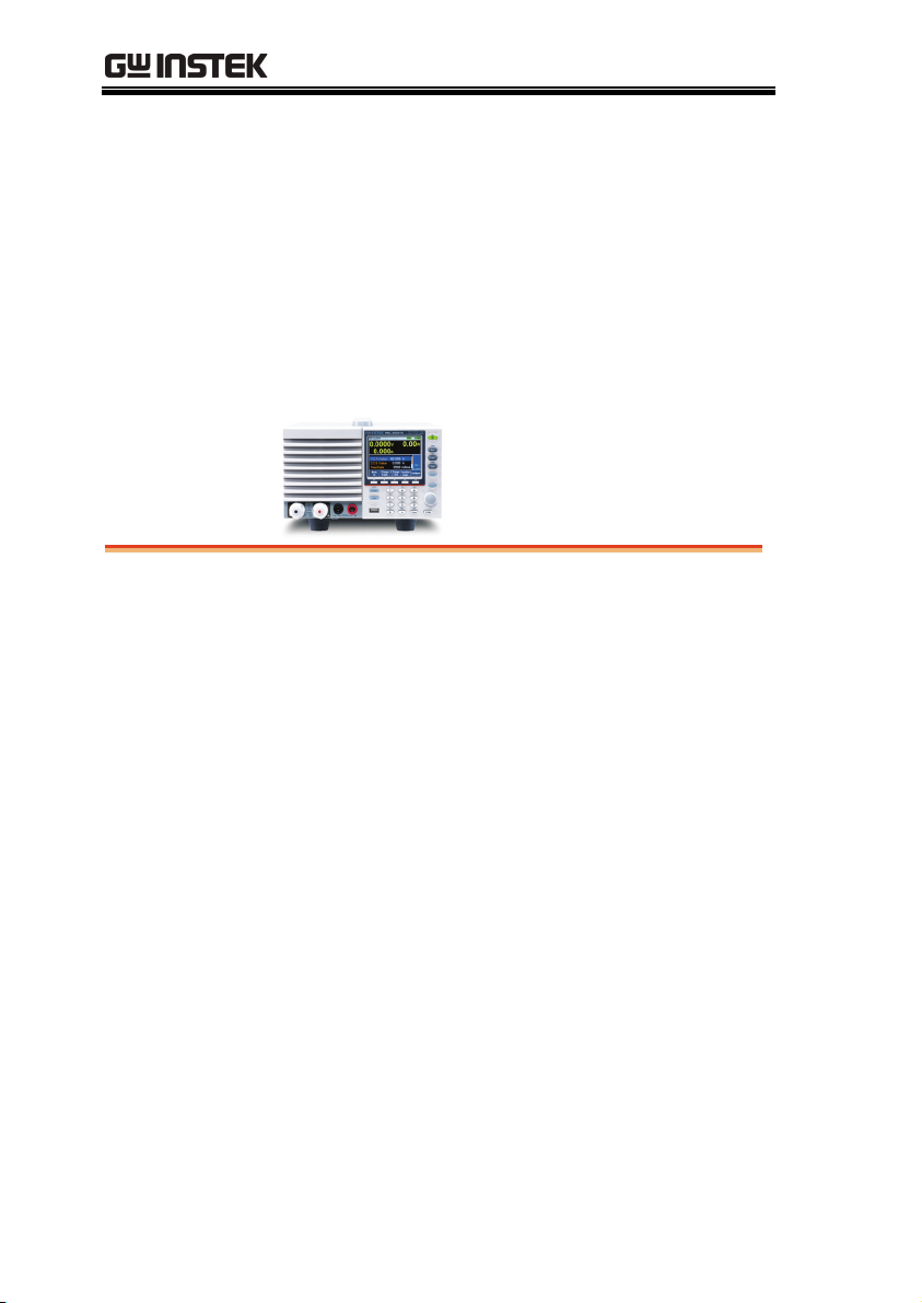
DC Electronic Load
PEL-3000E Series
USER MANUAL
VERSION: 1.11
ISO-9001 CERTIFIED MANUFACTURER
Page 2

This manual contains proprietary information, which is protected by
copyright. All rights are reserved. No part of this manual may be
photocopied, reproduced or translated to another language without
prior written consent of Good Will company.
The information in this manual was correct at the time of printing.
However, Good Will continues to improve products and reserves the
rights to change specification, equipment, and maintenance
procedures at any time without notice.
Good Will Instrument Co., Ltd.
No. 7-1, Jhongsing Rd., Tucheng Dist., New Taipei City 236, Taiwan.
Page 3

Table of Contents
Table of Contents
SAFETY INSTRUCTIONS ................................................... 3
GETTING STARTED ........................................................... 8
PEL-3000E Introduction ............................................. 9
Accessories ............................................................. 10
Appearance .............................................................. 12
First Time Use Instructions ..................................... 20
OPERATION .................................................................... 36
Basic Operation ....................................................... 39
Basic Configuration ................................................. 51
Advanced Configuration Settings ............................. 58
Step Resolution Configuration ................................. 69
Protection Settings .................................................. 72
System Settings ....................................................... 78
Go-NoGo ................................................................. 81
Program .................................................................. 84
Sequence ................................................................. 93
Save Recall ............................................................ 112
FUNCTION MENU ......................................................... 127
Function Menu Overview ....................................... 128
Program ................................................................ 134
Sequence ............................................................... 142
OCP Test Automation ............................................ 162
OPP Test Automation ............................................ 168
BATT Test Automation ........................................... 174
EXTERNAL CONTROL .................................................... 182
Analog Control ...................................................... 183
Trigger In/Out BNC ............................................... 199
1
Page 4

PEL-3000E Series User Manual
REMOTE CONTROL ....................................................... 201
Interface Configuration .......................................... 202
FAQ ............................................................................... 212
APPENDIX ..................................................................... 214
Replacing the Dust Filter ....................................... 215
GPIB Installation ................................................... 216
PEL-3000E Default Settings.................................... 217
Frame Control Connector Contacts ........................ 220
Operating Mode Description ................................. 222
Operating Area ...................................................... 227
PEL-3000E Specifications ....................................... 229
PEL-3000E Dimensions .......................................... 236
Declaration of Conformity ...................................... 237
INDEX ............................................................................ 238
2
Page 5
SAFETY INSTRUCTIONS
SAFETY INSTRUCTIONS
This chapter contains important safety
instructions that you must follow during
operation and storage. Read the following before
any operation to insure your safety and to keep
the instrument in the best possible condition.
Safety Symbols
These safety symbols may appear in this manual or on the
instrument.
WARNING
CAUTION
Warning: Identifies conditions or practices that
could result in injury or loss of life.
Caution: Identifies conditions or practices that
could result in damage to the instrument or to
other properties.
DANGER High Voltage
Attention Refer to the Manual
Earth (ground) Terminal
Frame or Chassis Terminal
Do not dispose electronic equipment as unsorted
municipal waste. Please use a separate collection
facility or contact the supplier from which this
instrument was purchased.
3
Page 6

PEL-3000E Series User Manual
Safety Guidelines
General
Guideline
CAUTION
Do not place any heavy object on the
Avoid severe impact or rough handling that
Do not discharge static electricity to the
Use only crimped wires, not bare wires, for the
Do not block the cooling fan opening.
Do not disassemble the instrument unless you
The equipment is not for measurements
(Measurement categories) EN 61010-1:2010 specifies the
measurement categories and their requirements as follows. The
instrument falls under category II.
Measurement category III is for measurement
Measurement category II is for measurement
0 is for measurements performed on circuits not
instrument.
leads to damaging the instrument.
instrument.
terminals.
are qualified.
performed for CAT II, III and IV.
Measurement category IV is for measurement
performed at the source of low-voltage
installation.
performed in the building installation.
performed on the circuits directly connected to
the low voltage installation.
directly connected to Mains.
4
Page 7

SAFETY INSTRUCTIONS
Power Supply
WARNING
Cleaning
Operation
Environment
AC Input voltage range:
100-120VAC/200-240VAC
(90-132VAC/180-250VAC)
Frequency: 47-63Hz
Power: 90VA Max
To avoid electrical shock connect the protective
grounding conductor of the AC power cord to
an earth ground.
Disconnect the power cord before cleaning.
Use a soft cloth dampened in a solution of mild
detergent and water. Do not spray any liquid.
Do not use chemicals containing harsh material
such as benzene, toluene, xylene, and acetone.
Location: Indoor, no direct sunlight, dust free,
almost non-conductive pollution (Note below)
Temperature: 0°C to 40°C
Humidity: 0 to 85% RH
Altitude: <2000m
(Pollution Degree) EN 61010-1:2010 specifies the pollution degrees
and their requirements as follows. The instrument falls under
degree 2.
Pollution refers to “addition of foreign matter, solid, liquid, or
gaseous (ionized gases), that may produce a reduction of dielectric
strength or surface resistivity”.
Pollution degree 1: No pollution or only dry,
non-conductive pollution occurs. The pollution
has no influence.
Pollution degree 2: Normally only non-
conductive pollution occurs. Occasionally,
however, a temporary conductivity caused by
condensation must be expected.
Pollution degree 3: Conductive pollution occurs,
or dry, non-conductive pollution occurs which
becomes conductive due to condensation which
5
Page 8

PEL-3000E Series User Manual
is expected. In such conditions, equipment is
normally protected against exposure to direct
sunlight, precipitation, and full wind pressure,
but neither temperature nor humidity is
controlled.
Storage
environment
Disposal
Location: Indoor
Temperature: -20°C to 70°C
Humidity: <90% RH
Do not dispose this instrument as unsorted
municipal waste. Please use a separate collection
facility or contact the supplier from which this
instrument was purchased. Please make sure
discarded electrical waste is properly recycled to
reduce environmental impact.
6
Page 9

SAFETY INSTRUCTIONS
Power cord for the United Kingdom
When using the instrument in the United Kingdom, make sure the
power cord meets the following safety instructions.
NOTE: This lead/appliance must only be wired by competent persons
WARNING: THIS APPLIANCE MUST BE EARTHED
IMPORTANT: The wires in this lead are coloured in accordance with the
following code:
Green/ Yellow: Earth
Blue: Neutral
Brown: Live (Phase)
As the colours of the wires in main leads may not correspond with
the coloured marking identified in your plug/appliance, proceed
as follows:
The wire which is coloured Green & Yellow must be connected to
the Earth terminal marked with either the letter E, the earth symbol
or coloured Green/Green & Yellow.
The wire which is coloured Blue must be connected to the terminal
which is marked with the letter N or coloured Blue or Black.
The wire which is coloured Brown must be connected to the
terminal marked with the letter L or P or coloured Brown or Red.
If in doubt, consult the instructions provided with the equipment
or contact the supplier.
This cable/appliance should be protected by a suitably rated and
approved HBC mains fuse: refer to the rating information on the
equipment and/or user instructions for details. As a guide, a cable
of 0.75mm
conductors would normally require 13A types, depending on the
connection method used.
Any exposed wiring from a cable, plug or connection that is
engaged in a live socket is extremely hazardous. If a cable or plug is
deemed hazardous, turn off the mains power and remove the cable,
any fuses and fuse assemblies. All hazardous wiring must be
immediately destroyed and replaced in accordance to the above
standard.
2
should be protected by a 3A or 5A fuse. Larger
7
Page 10
PEL-3000E Series User Manual
GETTING STARTED
This chapter provides a brief overview of the
PEL-3000E, the package contents, instructions for
first time use and an introduction to the front
panel, rear panel and GUI.
PEL-3000E Introduction ............................................. 9
Overview ........................................................................................... 9
Main Features ................................................................................... 9
Accessories .............................................................. 10
Package Contents ...........................................................................11
Appearance .............................................................. 12
PEL-3000E Front Panel (PEL-3031E/PEL-3032E) ................12
Rear Panel (PEL-3031E/PEL-3032E) ........................................16
Display .............................................................................................19
First Time Use Instructions ..................................... 20
Power Up and Self Test .................................................................20
Load Default Settings ....................................................................21
Load Wiring ....................................................................................21
Load Wire Connections .................................................................24
Using the Front Panel Input Terminals ......................................25
Remote Sense ..................................................................................26
Firmware Update ............................................................................27
Conventions ....................................................................................29
Help Menu ......................................................................................35
8
Page 11

GETTING STARTED
PEL-3000E Introduction
The PEL-3000E is an economic, standalone, high performance DC
electronic load positioned to test a wide range of different power
sources. The DC electronic load is fully programmable to simulate
anything from basic static loads to complex dynamic loads. The
PEL-3000E is extremely robust and capable of molding to any test
environment.
Overview
Model Operating Voltage (DC) Current Power
PEL-3031E
PEL-3032E
1V-150V
2.5V-500V
Main Features
Performance
High slew rates of up to 2.5A/μs (PEL-3031E)
for a fast response speed
High resolution – 16 bit
6A (Low range)
60A (High range)
1.5A (Low range)
15A (High range)
300W
300W
Features
7 operating modes: CC, CV, CR, CP, CC+CV,
CR+CV, CP+CV
Fully programmable with normal and fast
sequences
Soft start
Dynamic mode
OCP, OVP and other protection features
Remote sense
Integrated meter
Rack-mountable
9
Page 12
PEL-3000E Series User Manual
Interface
USB and GPIB
External voltage or resistance control
Rear panel trigger in/out BNC
Analog external control
Accessories
Standard
Accessories
Quick Start Guide
User / Programming manual
Region dependent Power cord
61SF-062104N1 Front terminal washers
GTL-105A Remote sense cables, red x1,
Optional
Accessories
Part number Description
CD
black x1
Part number Description
GTL-248 GPIB cable, 2.0m
GTL-246 USB cable, Type A - Type B
PEL-010 Dust Filter
Options Part number Description
PEL-004 GPIB option
10
Page 13
GETTING STARTED
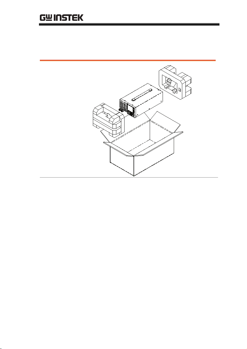
Package Contents
Check the contents before using the instrument.
Opening the box
Contents
(single unit)
Main unit
Quick Start manual
User / Programming
Power cord x1
(region dependent)
Calibration certificate
manual CD
11
Page 14
PEL-3000E Series User Manual
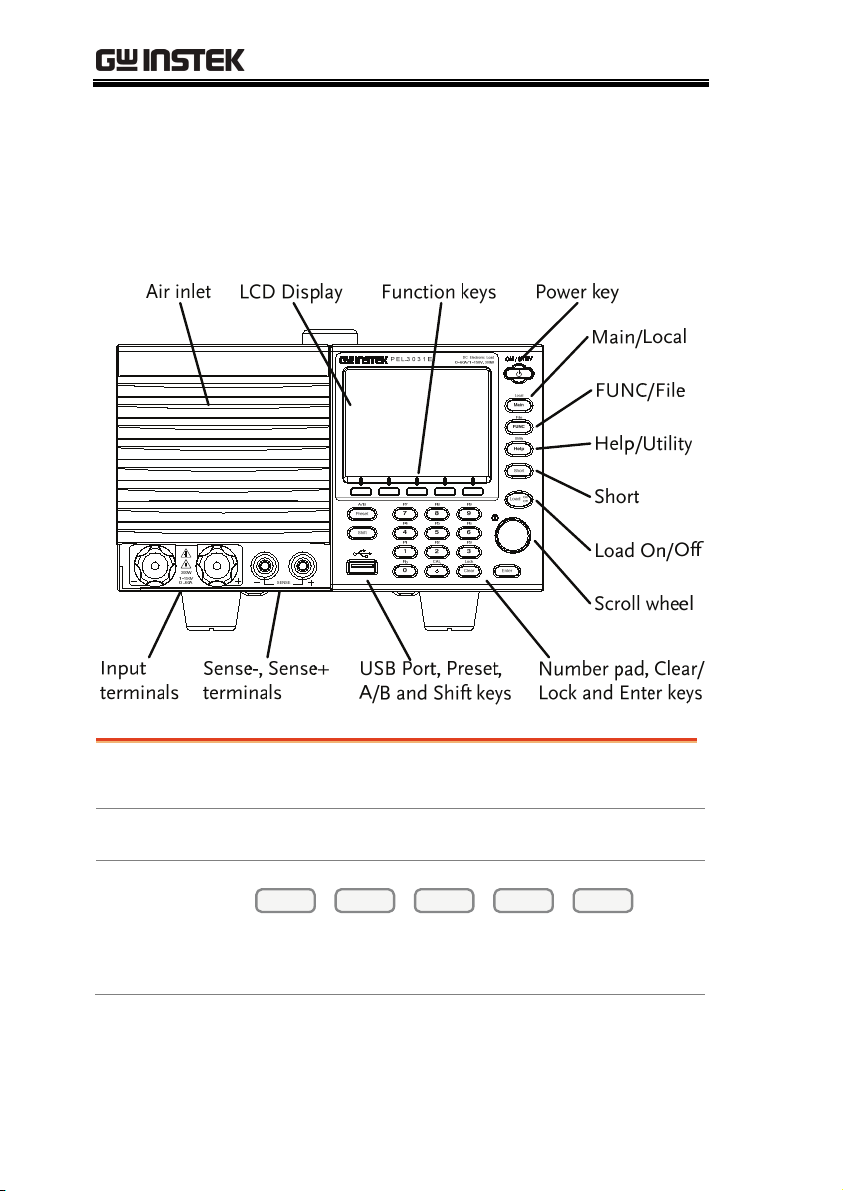
Appearance
PEL-3000E Front Panel
(PEL-3031E/PEL-3032E)
Air Inlet
LCD display
Function keys
12
The air inlet has a removable dust filter
3.5 inch LCD display
The function keys directly correspond to the soft
menu keys at the bottom of the display.
Page 15
GETTING STARTED
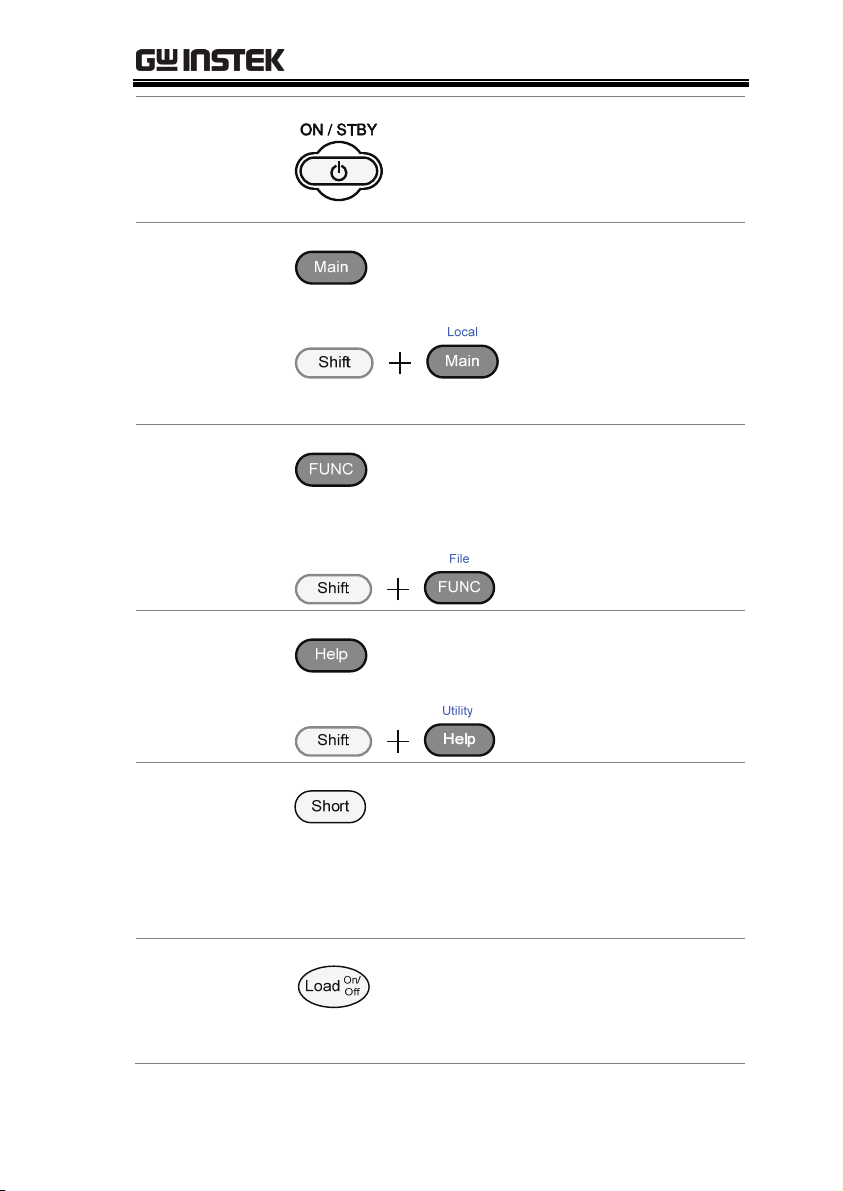
ON/STBY
Main/Local
FUNC/File
Help/Utility
Turns the unit on or puts the unit
into standby mode. Use the
power switch on the rear panel to
turn the unit off.
Main: Sets the operating mode:
CC, CV, CR, CP mode.
Local (Shift + Main): Puts
the instrument back into
local mode from remote
mode.
FUNC: Sets the program
function, sequence function or
other special functions.
File (Shift + FUNC):
Accesses the file system.
Help: Access the help menu.
Utility (Shift + Help):
Access the utility menu.
Short
Pressing the Short key will
simulate shorting the input
terminals.
The Short key will be lit when
active.
Load on/off
Turns the load on or off.
The Load On/Off key will be lit
when active.
13
Page 16
PEL-3000E Series User Manual
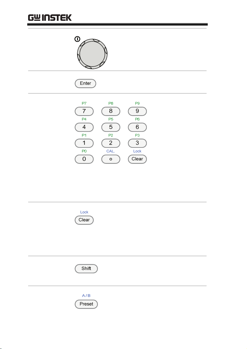
Scroll wheel
Enter
Number pad
Use the scroll wheel to navigate
the menu system or to edit
parameters. See page 29 for usage
details.
Press the Enter key to select
highlighted menu items.
Number pad: Used to enter numerical values.
P0-P9 (Preset + Number keys): Loads one of 10
preset settings.
Clear/Lock
Clear: Clears the current
parameter values.
Lock (Shift + Clear): Locks the
front panel keys and selector
knob.
Shift
Shift: Used in conjunction with
other keys to select secondary
functions.
Preset
14
Used in conjunction with the
number pad to save or load preset
settings P0 to P9.
Page 17
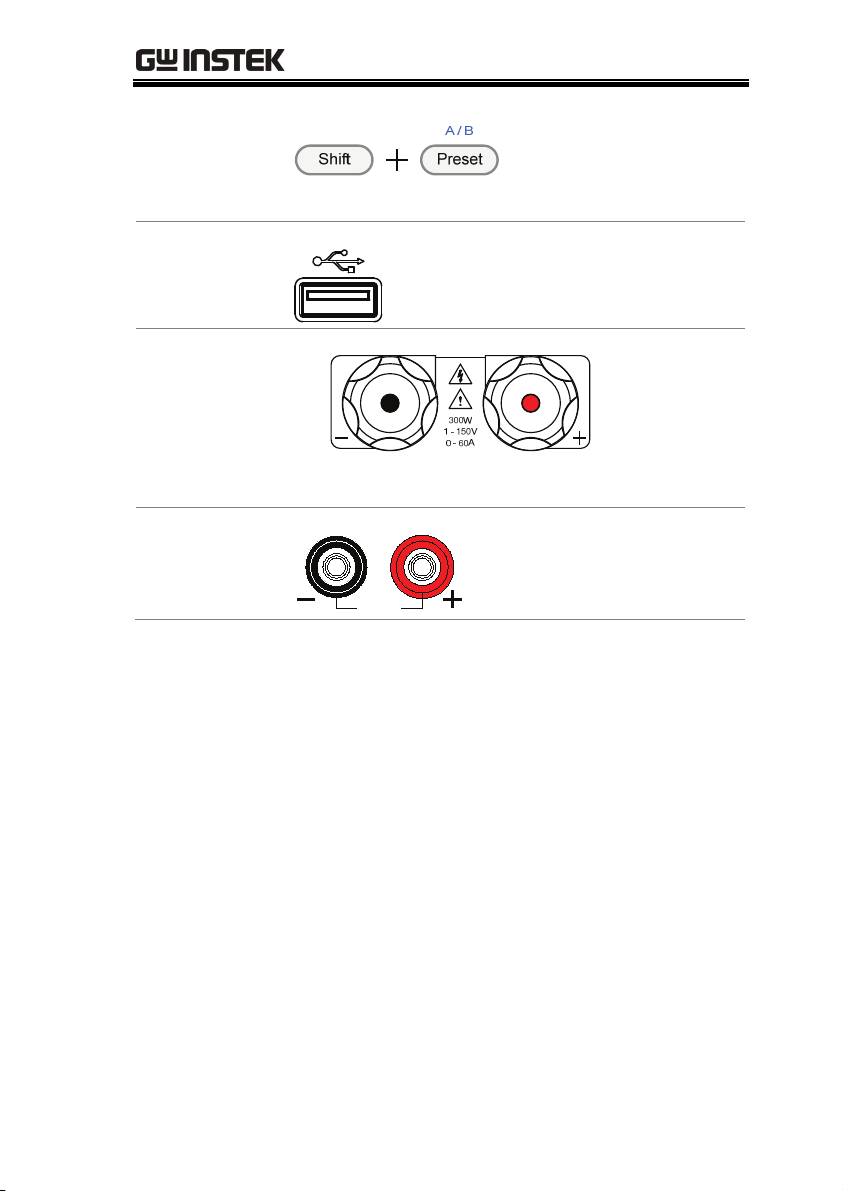
GETTING STARTED
USB Port
Front panel input
terminals
Sense Ports
The A/B function is used
to manually switch from
Level A to Level B when
in CC or CR static mode.
USB A port. Used for save and
recall functions.
Negative terminal. Positive terminal.
Sensing ports for remote
sense. See page 26.
15
Page 18
PEL-3000E Series User Manual
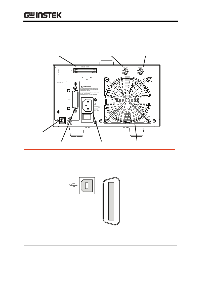
Rear Panel (PEL-3031E/PEL-3032E)
J1 Frame control ports
(Analog control connector)
USB device port
GPIB
The USB B and GPIB port are used for remote
control.
USB B
Trigger out
port
Power socket
Trigger in port
Exhaust fanGPIB(optional)
USB B port
16
GPIB 24 pin
female.
Page 19
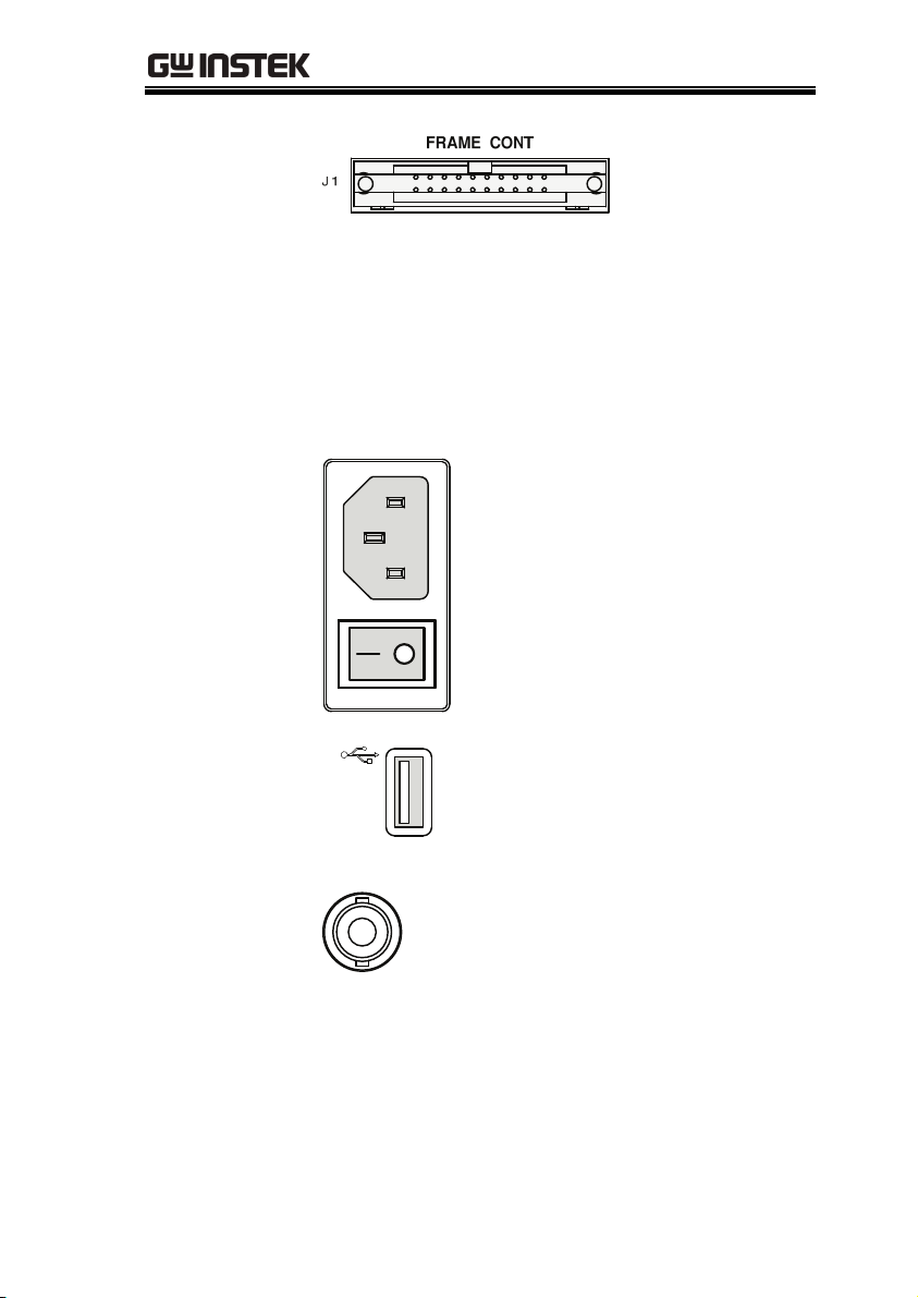
J1 Frame control
ports (Analog
control
connector)
GETTING STARTED
Exhaust fan
Power Socket
Power Switch
USB A
TRIG OUT
The J1 connector is assigned to perform external
control and monitoring.
The exhaust fan is used to expel the heat from the
unit. Please ensure there is at least 20cm distance
between any object and the fan.
Power Socket:
100-120V, 200-240V
47-63Hz.
Turns the unit on/off.
USB A Slave port. USB 1.1/2.0
TRIG OUT
Trigger out BNC terminal:
Outputs a pulse signal during
sequence or dynamic operation.
The trigger signal has a 4.5V
output with a pulse width of a
least 2us and an impedance of
500Ω.
17
Page 20

PEL-3000E Series User Manual
TRIG IN
Trigger input BNC terminal:
This terminal is used to externally
resume sequences that have been
paused. Pulled down internally to
ground by a 100kΩ resistor.
18
Page 21
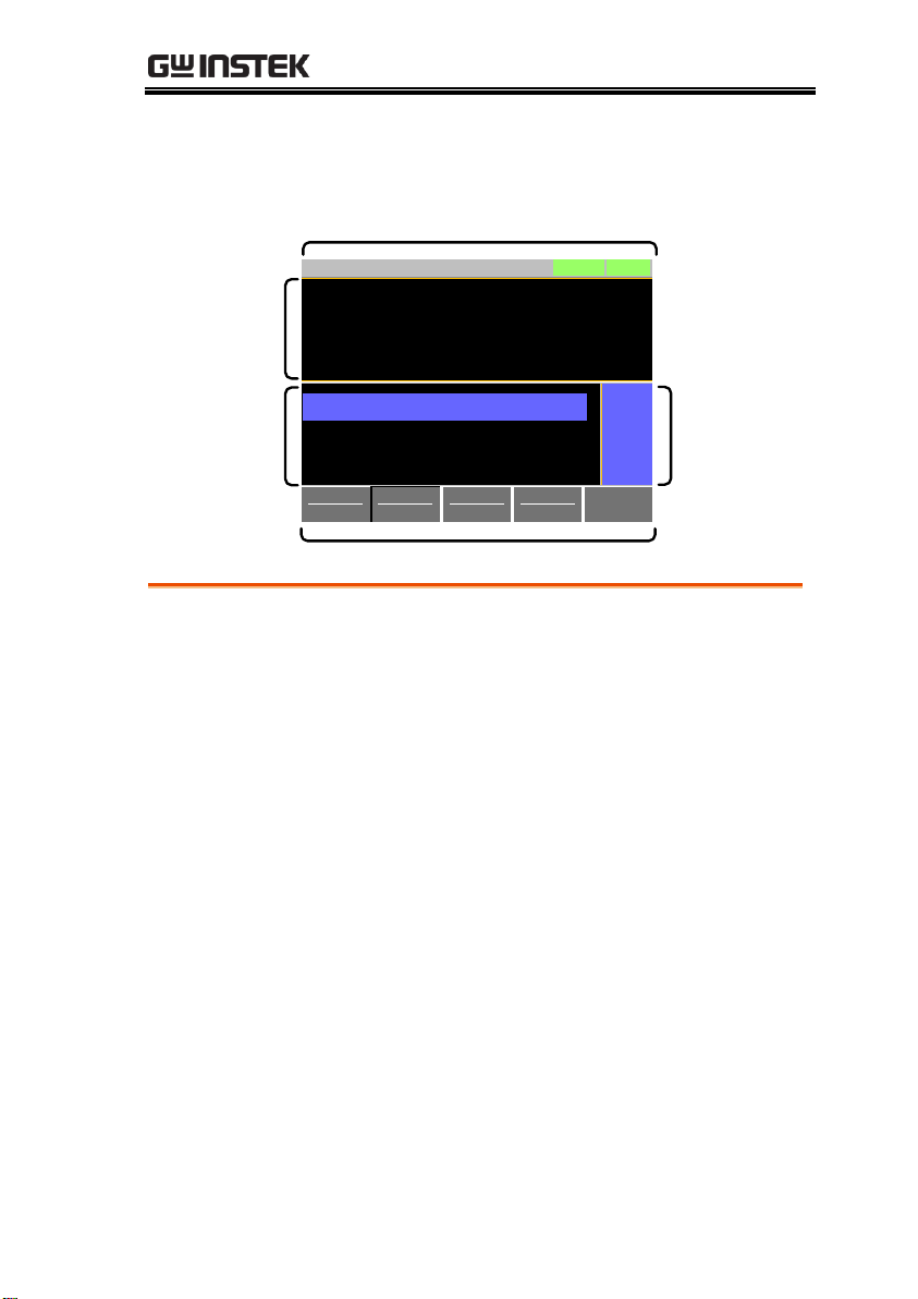
Display
Setting area
Operation
status panel
Measurement
area
Mainframe status panel
Softkeys
ModeCCI Range
H 60A
V Range
L 15V
Function
Static
Configure
0.0000
V
0.000
A
0.00
w
SlewRate 2500
CC B Value 0.000
CC A Value 0.000
LOADUSB
A Value
Fine
mA/us
A
A
Setting Area
The setting area is used to display and edit the
settings for the current mode/function.
Measurement
Area
Displays the voltage, current and power values.
Mainframe Status
Panel
The mainframe status panel displays the status of
the load, remote control and short function.
When an icon is green it indicates that the
function is off. When the icon is orange, the
function is on.
Operation Status
Panel
This status panel is used to display the status of
the current mode.
Soft-keys
The soft-key menus are used to select different
functions or parameters.
GETTING STARTED
19
Page 22
PEL-3000E Series User Manual
First Time Use Instructions
Use the procedures below when first using the PEL-3000E to install
the rack mount kit, power up the instrument, restore the factory
default settings and check the firmware version. Lastly, the
Conventions section will introduce you to the basic operating
conventions used throughout the user manual.
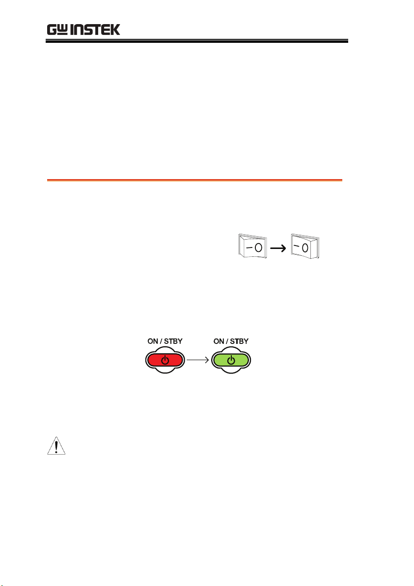
Power Up and Self Test
Steps
Note
1. Insert the AC power cord into the power
socket.
2. Turn the external
power switch on.
(O → —)
3. If the unit doesn’t turn on, press the
On/Standby key.
The ON/STBY key will go from standby (red)
to on (green).
4. The unit will show the splash screen and then
load the settings from when the unit was last
powered down.
If the PEL-3000E fails to start up properly or does
not turn on, please see you local distributor.
20
Page 23
GETTING STARTED
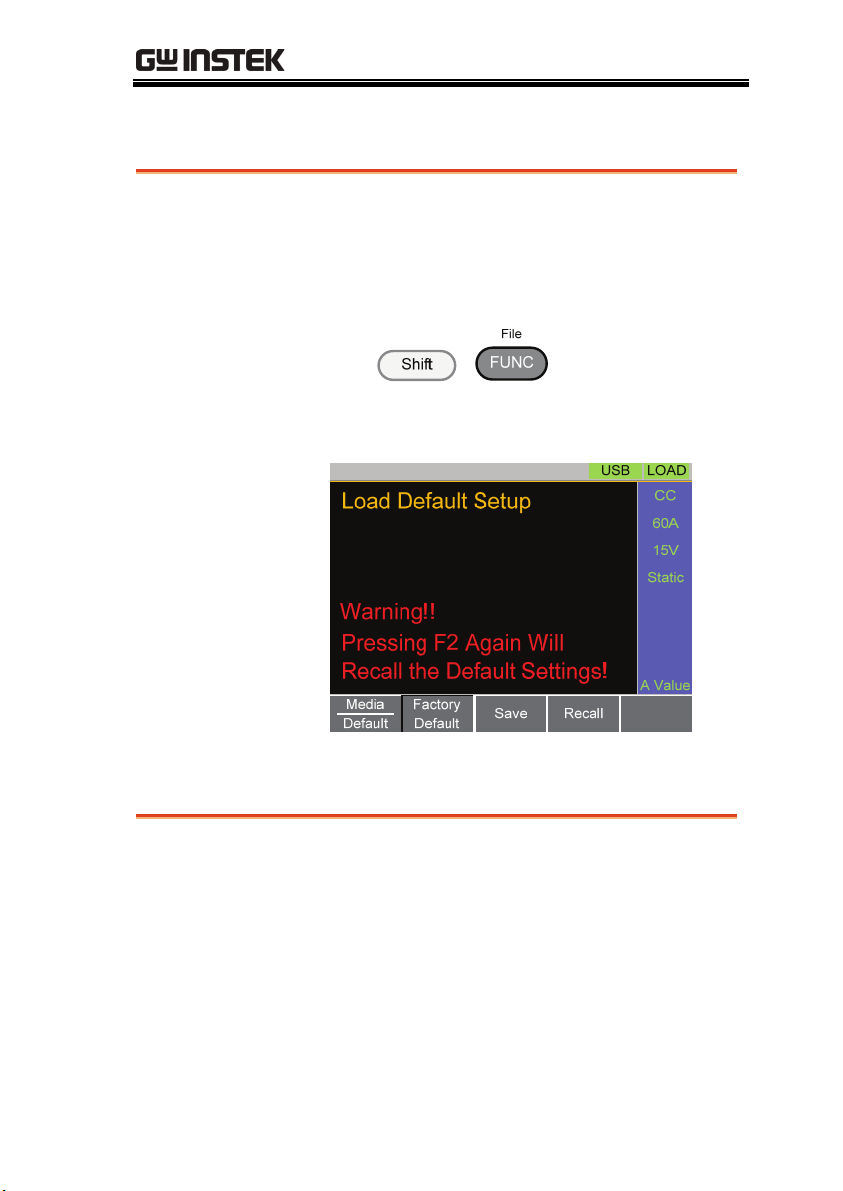
Load Default Settings
Description
Operation
Load Wiring
When first using the PEL-3000E, recall the
factory default settings to ensure the unit is in
a known state. See page 217 for a list of the
default settings.
1. Press
+
.
Select Media/Default[F1].
Select Factory Default[F2].
Wire Gauge
considerations
Before connecting the unit to a power source,
the wire gauge must be taken into account.
Load wires must be large enough to resist
overheating when a short-circuit condition
occurs as well as to maintain a good
regulation. The size, polarity and length of a
wire are all factors in determining if a wire
will withstand short circuiting.
21
Page 24

PEL-3000E Series User Manual
Load Line
Inductance
Considerations
Wires that are selected must be large enough
to withstand a short circuit and limit voltage
drops to no more than 2V per wire. Use the
table below to help make a suitable selection.
AWG
Gauge
Conduct or
Diameter
mm
Ohms per
km
Max
amps for
chassis
wiring
8
9
10
11
12
13
3.2639 2.0605 73
2.90576 2.59809 64
2.58826 3.27639 55
2.30378 4.1328 47
2.05232 5.20864 41
1.8288 6.56984 35
14 1.62814 8.282 32
When using the PEL-3000E load generator,
voltage drop and voltage generated due to
load line inductance and current change must
be taken into account. Extreme changes in
voltage may exceed the minimum or
maximum voltage limits. Exceeding the
maximum voltage limit may damage the PEL3000E.
To determine the voltage generated, the
following equation can be used.
E = L x (∆ I / ∆ T)
E= voltage generated
L=load line inductance
∆ I= change of current (A)
∆ T= time (us)
Load line inductance (L) can be approximated
as 1uH per 1 meter of wire. (∆ I / ∆ T) is the
22
Page 25

GETTING STARTED
slew rate in A/us.
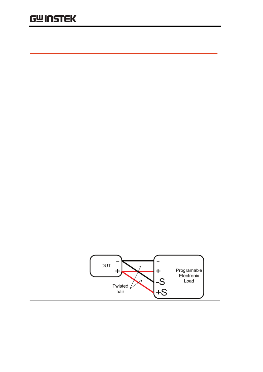
Limiting Load line
inductance
The diagram above shows how changes in current
can affect voltage.
Load line inductance can be reduced in two
ways.
1. Ensure load wires are as short as possible
and twist the positive and negative load wires
together.
2. Current change can be limited by limiting
the slew rate speed when switching in CR and
CC mode.
“Twisted pair” will be shown on any
connection diagram where the load wires
should be twisted together.
23
Page 26
PEL-3000E Series User Manual
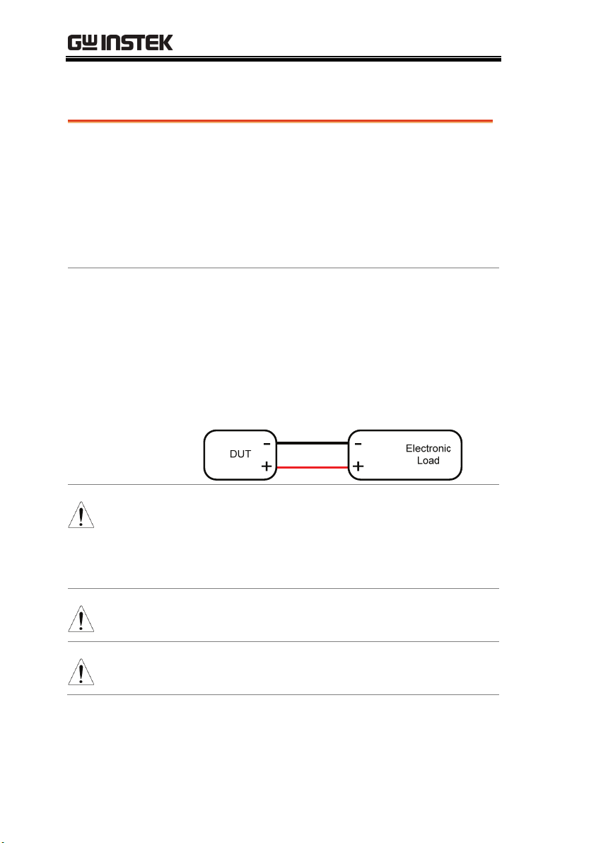
Load Wire Connections
Description
Connection
Caution
The PEL-3000E has input terminals on the
front panel.
Follow the procedures below for the load
connection. Please adhere to the following
precautions to ensure your safety and to
protect the unit from damage.
When connecting the PEL-3000E to the DUT,
make sure that the polarity of the connection
between the DUT and the unit matches.
Ensure that the maximum input voltage is not
exceeded. The maximum input voltage is 150
volts (PEL-3031E).
If the polarity to the input terminals is reversed,
the reverse voltage protection function is tripped.
The reverse voltage protection function is tripped
when reverse voltages greater than -0.3V are
detected.
Warning
unit is on.
Connecting the input terminals to the wrong
Do not touch any of the input terminals when the
Warning
24
polarity can damage the DUT or the PEL-3000E.
Page 27
GETTING STARTED
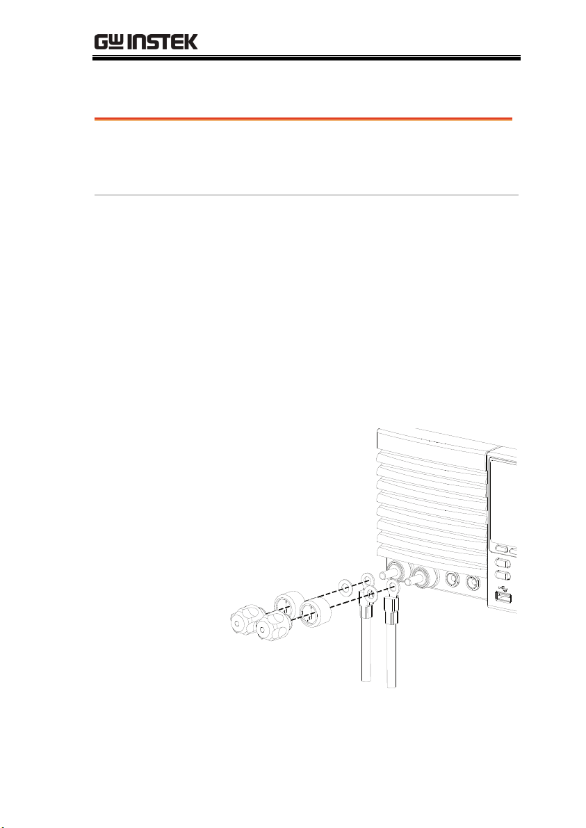
Using the Front Panel Input Terminals
Description
Steps
The front panel input terminals feature
polarity-distinct caps and accept M6 sized
crimped terminals.
1. Turn the power off from the rear panel or put
the unit into standby mode.
2. Turn the power off from the DUT.
3. Connect the load wires to the input terminals:
Connect the positive (+) input terminal on the
load generator to the high potential output of
the DUT.
Connect the negative (-) input terminal to the
low potential output of the DUT.
Negative
terminal
Positive
terminal
-potential
+ potential
25
Page 28
Remote Sense
PEL-3000E Series User Manual
Description
Steps
Remote sense can be used to help compensate
for long cable length. The longer the cable, the
higher the potential resistance and inductance,
therefore a short cable is best. Twisting the
cable can help reduce induced inductance and
using the Vsense terminals compensates the
voltage drop seen across the load leads,
especially leads with higher resistance. This is
useful when used in CV, CR or CP mode.
1. Turn the power off from the rear panel or put
the unit into standby mode.
2. Turn the power off from the DUT.
3. Connect the DUT to the load terminals, see
page 21, 24.
4. Connect the sense wires to the sense terminals:
Connect the positive sense (+S) terminal to the
high potential output of the DUT.
Connect the negative sense (-S) terminal to the
low potential output of the DUT.
26
Page 29

GETTING STARTED
Warning
Firmware Update
Description
System version
Operation
1. Press
Ensure that the load is connected to the DUT
before connecting the sense wires. If only the
sense wires are connected to the DUT, the load
will be seen at the sense terminals. This will result
in an internal fuse entering a high-impedance
state due to over temperature. At this point, any
measured values will be erroneous. You must wait
for the temperature to return to normal operating
temperature before the unit should be used again.
The PEL-3000E allows the firmware to be
updated by end-users. Before using the PEL3000E, please check the GW Instek website or
ask your local distributor for the latest
firmware.
Before updating the firmware, please check
the firmware version.
+
.
2. Select System/Info[F1].
3. The System information is listed on the
display.
Model: PEL-3000E model number.
Serial Number: XXXXXXXX
Firmware Ver.: X.XX.XXX.
Website address.
4. To view other system information, press
System[F1] and select Memo.
27
Page 30

PEL-3000E Series User Manual
Update Firmware
Note
1. Insert a USB drive into the USB port. Ensure
the USB drive has the firmware file located in
the root directory.
2. Press
+
.
3. Select USB with the Media[F1] soft-key.
4. Press the File Utility[F5] soft-key.
5. Select the *.UPG upgrade file and press
Select[F1] twice. Once to select the file and
once to confirm.
6. Wait for the update to complete and reset the
power when prompted.
Do not turn the load generator off or remove the
USB memory when the firmware is being read or
upgraded.
28
Page 31

GETTING STARTED
Conventions
The following conventions are used throughout the user manual.
Read the conventions below for a basic grasp of how to operate the
PEL-3031E menu system using the front panel keys.
Soft Menu keys
Select Sub Menu
The F1 to F5 function keys at the bottom of the
display correspond directly to the soft-menu
keys on top.
Pressing this type of soft-menu key will enter
a submenu.
29
Page 32
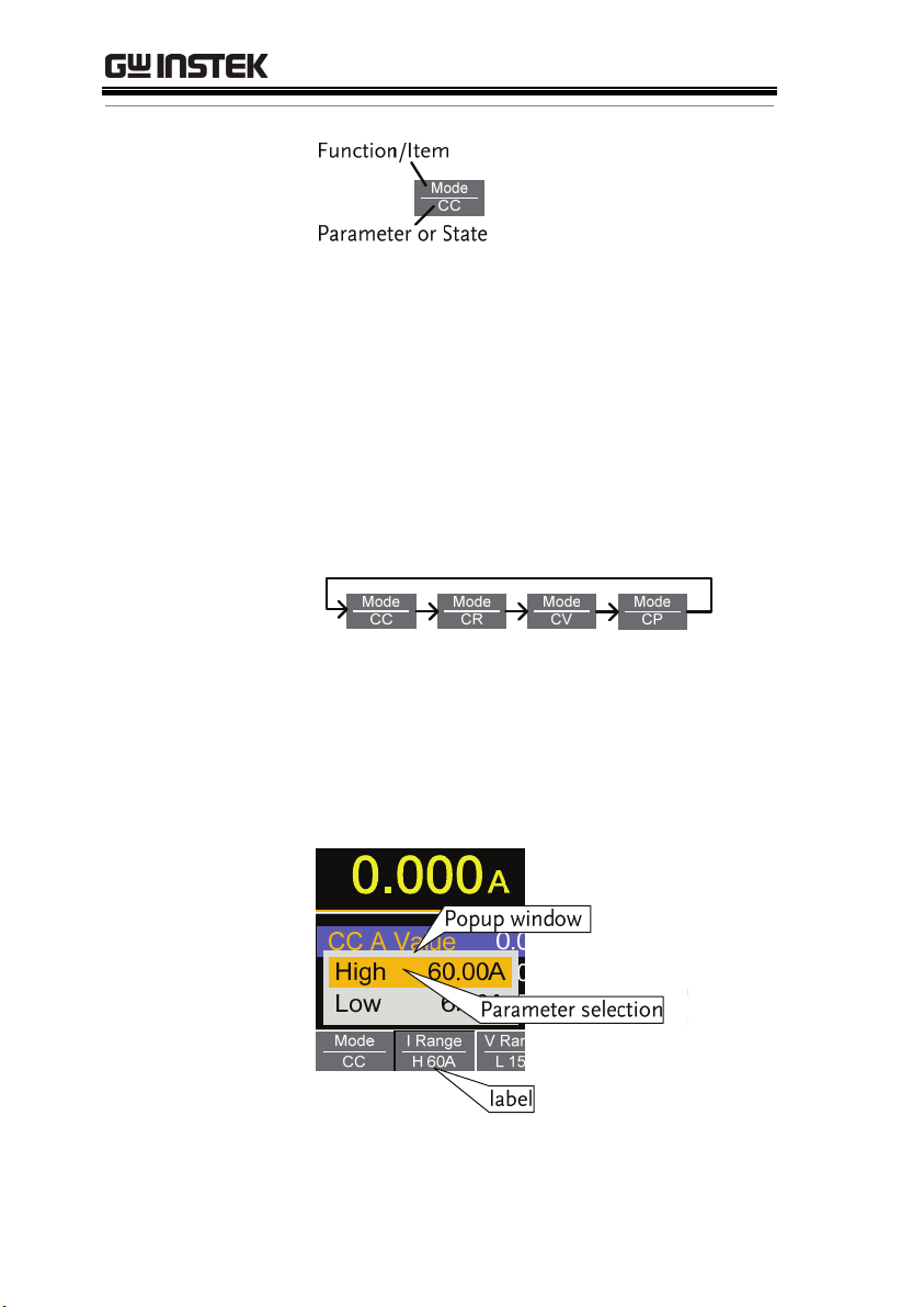
Toggle Parameter
or State
PEL-3000E Series User Manual
This type of soft-menu icon has the
function/item on the top of the label and the
selected setting or mode on the bottom of the
label.
Repeatedly press the associated function key
(F1-F5) to cycle through each setting. For
example, repeatedly pressing the Mode soft-
menu key will cycle through the CC, CR, CV
and CP modes.
For some parameters, a popup window will
also appear. Selection of the setting is the
same. Repeatedly pressing the relevant
function key (F1-F5) will cycle through each
setting. The selection on the popup window
will also be reflected on the label.
30
Page 33

GETTING STARTED
Parameter Input
The scroll wheel, Enter key and number pad
can be used to edit parameter values.
Number pad
Scroll wheel
Enter key
P0
P1
P4
P7
CAL.
P2
P5
P8
Lock
P3
P6
P9
0
1
4
7
2
5
8
3
6
9
Clear Enter
1. Use the scroll wheel to move the cursor to the
desired parameter.
A scroll bar is shown when there are additional
parameters off-screen.
ModeCPI Range
H 60A
V Range
L 15V
Response
Fast
Configure
0.0000
V
0.000
A
0.00
w
+CV OFF
CP B Value 0.00
CP A Value 0.00
LOADUSB
Fine
V
W
W
A Value
Scroll bar
Cursor
2. Press the Enter key to select the parameter.
The parameter will become highlighted in
white.
31
Page 34

PEL-3000E Series User Manual
3. Then use the number pad* or scroll wheel** to
edit the parameter value.
ModeCPI Range
H 60A
V Range
L 15V
Response
Fast
Configure
0.0000
V
0.000
A
0.00
w
+CV OFF
CP B Value 0.00
CP A Value
LOADUSB
Fine
V
W
W
A Value
0.00
Parameter
4. Press the Enter key again to finish editing the
parameter value.
Clearing a Value*
*When editing a parameter with the number
pad, pressing the
Clear
key will restore the
parameter to the previous value.
Using the Scroll
Wheel to Edit a
Parameter**
**To edit a parameter using the scroll wheel,
simply turn the scroll wheel. Clockwise
increases the value, counterclockwise decrease
the value.
Pressing the scroll wheel when a parameter is
highlighted allows you to change the step
resolution. There are two different step
resolution methods: Step Mode and Cursor
Mode.
32
Page 35

GETTING STARTED
Step Mode: This is the default step resolution
method and will only be available to use when
it is applicable (Indicated by Fine or Coarse in
the Operation Status panel).
When a parameter is highlighted (step 3 above)
pressing the scroll wheel will toggle the step
resolution between fine and coarse. For details
on how to set the step resolution, see page 70.
ModeCPI Range
H 60A
V Range
L 15V
Response
Fast
Configure
0.0000
V
0.000
A
0.00
w
+CV OFF
CP B Value 0.00
CP A Value
LOADUSB
Fine
V
W
W
A Value
0.00
+
Coarse/Fine
adjustment
Higlighted
parameter
Cursor Mode: This method must first be
enabled before it can be used. Pressing the
scroll wheel when a parameter is highlighted
allows you to set the step resolution by a digit
value. An orange line will appear under the
currently selected digit value. Repeatedly
pressing the scroll wheel moves to the next
digit. See page 69 for details.
ModeCPI Range
H 60A
V Range
L 15V
Response
Fast
Configure
0.0000
V
0.000
A
0.00
w
+CV OFF
CP B Value 0.00
CP A Value
LOADUSB
Cursor
V
W
W
A Value
0.00
+
Cursor
Mode
Indicator
Higlighted
parameter
Cursor
position
0.00
w
LOADUSB
W
0.00
33
Page 36

PEL-3000E Series User Manual
Entering
Alphanumeric
Characters
When renaming files, creating memos or
notes, you will be required to enter
alphanumeric characters when the character
entry screen appears.
Only alphanumeric characters as well as space
[ ], underscore [_] and minus [-] characters
allowed.
1. Use the scroll wheel to move the cursor to the
desired character.
2. Press the
key or Enter Character[F1]
to select a character.
OR
3. To delete a character, press Back Space[F2].
4. To save the file name or memo, press Save[F3].
34
Page 37

GETTING STARTED
Help Menu
When any function key has been pressed or when a menu has been
opened, the HELP key can be used to display a detailed description.
Help Selection
1. Press any function key or soft-menu key.
2. Press
to see the help contents on that
particular function key or menu.
3. Use the scroll to navigate the help contents.
4. Press the Exit[F5] key to exit the help menu.
35
Page 38

PEL-3000E Series User Manual
OPERATION
Basic Operation ....................................................... 39
CC Mode .........................................................................................39
CR Mode .........................................................................................41
CR Units ................................................................................................ 43
CV Mode .........................................................................................43
CP Mode ..........................................................................................45
+CV Mode ......................................................................................46
Turning on the Load ......................................................................48
Shorting the Load ...........................................................................49
Short Key Configuration ..................................................................... 50
Locking the Front Panel Controls ...............................................50
Basic Configuration ................................................. 51
Select the Switching Function ......................................................51
Select the Display Units for Dynamic Mode Levels ....................... 54
Select the Switching Time Configuration for Dynamic Mode ...... 55
Slew Rate .........................................................................................55
CV/CP Mode Response Speed ....................................................56
Advanced Configuration Settings ............................. 58
Soft Start Setting .............................................................................58
Von Voltage Settings .....................................................................59
Von Voltage Level ............................................................................... 59
Von Voltage Latch ............................................................................... 60
Von Voltage Delay ............................................................................... 61
Timer Functions .............................................................................61
Count Time ........................................................................................... 61
Cut Off Time ........................................................................................ 62
Auto Load Configuration ..............................................................63
Load Off (Mode) and Load Off (Range) ....................................64
Short Safety .....................................................................................65
Short Function Enable/Disable ........................................................ 65
Locking the Front Panel Controls ...............................................66
Input/Output Trigger Settings .....................................................67
Trigger In Status ................................................................................... 67
Trigger In Delay ................................................................................... 67
Trigger Out Status ................................................................................ 67
Trigger Out Width ............................................................................... 68
36
Page 39

OPERATION
Step Resolution Configuration ................................. 69
Cursor Mode Configuration ........................................................ 69
Step Mode Configuration ............................................................. 70
Protection Settings .................................................. 72
OCP ................................................................................................ 72
OPP ................................................................................................. 73
UVP ................................................................................................. 75
OVP ................................................................................................ 76
UnReg ............................................................................................. 77
System Settings ....................................................... 78
Sound Settings ............................................................................... 78
Speaker Settings .................................................................................... 78
Alarm Tone Settings ............................................................................ 79
Display Settings ............................................................................. 79
Contrast and Brightness ...................................................................... 79
Control Settings ............................................................................. 80
Language Settings .......................................................................... 80
Go-NoGo ................................................................. 81
Setting the Go-NoGo Limits ....................................................... 81
Running a Go-NoGo Test ........................................................... 82
Program .................................................................. 84
Program Overview ........................................................................ 84
Create a Program ........................................................................... 86
Create a Program Chain ............................................................... 90
Running a Program or Chain ....................................................... 91
Sequence ................................................................. 93
Normal Sequence Overview ........................................................ 93
Timing Edit Configuration ................................................................. 98
Data Edit Configuration ..................................................................... 99
Running a Normal Sequence ..................................................... 101
Fast Sequence Overview ............................................................ 103
Timing Edit Configuration ............................................................... 107
Data Edit Configuration ................................................................... 108
Running a Fast Sequence ........................................................... 110
Save Recall ............................................................ 112
File Structure ....................................................................................... 112
File Types ............................................................................................ 113
Saving Files to Internal Memory ...................................................... 115
Saving Files to USB Memory ........................................................... 116
Recalling Files from Internal Memory ............................................ 119
Recalling Files from USB Memory .................................................. 120
Recall Memory Safety Setting ........................................................... 122
File Utility ..................................................................................... 123
37
Page 40

PEL-3000E Series User Manual
Preset............................................................................................. 124
Quick Preset Save ..............................................................................124
Quick Preset Recall ............................................................................125
Default Settings ........................................................................... 125
Factory Default Settings ....................................................................125
User’s Default Setting ........................................................................126
38
Page 41

OPERATION
g
g
Basic Operation
The PEL-3000E supports 7 main operating modes:
CC, CC+CV;
CR, CR+CV;
CV;
CP, CP+CV
CC Mode
Description
Warning
Operation
In Constant Current Mode the load units will
sink the amount of current programmed.
Regardless of the voltage, the current will stay
the same. For more details on CC mode, please
see the Appendix on page 222.
If you change the mode or the range when the
load is already on, the load will be turned off
automatically.
1. Make sure the load is off.
2. Press
3. Select CC mode with the Mode[F1] soft-key.
4. Select the current range with the I Range[F2]
soft-key.
Range:
5. Select the voltage range with the V Range[F3]
soft-key.
Range:
Hi
Hi
.
h, Low
h, Low
39
Page 42

PEL-3000E Series User Manual
Display
6. Set the current level parameters using the
scroll wheel and number pad.
For Static mode, set CC A Value and/or CC B
Value.
For Dynamic mode, set Level1 and Level2.
The maximum and minimum current levels
depend on the selected ranges.
7. To add CV mode to CC mode (CC+CV), see
page 46.
1. Set the remaining basic configuration settings
such as the slew rate and switching mode
settings. See page 51 for details.
Note
page 51 for more configuration options.
The current range and voltage range only applies
to CC, CV & CP modes. For CR mode, the voltage
range and conductance/resistance ranges are
separate from the other modes.
Basic CC mode configuration is complete. See
40
Page 43

CR Mode
g
OPERATION
Description
Warning
Operation
In Constant Resistance Mode, the unit will
maintain a constant resistive load by varying
the current. CR mode uses ohms, Ω (resistance)
or siemens, S (conductance) for the setting
units. For more details on CR mode, see the
appendix on page 223.
If you change the mode or the range when the
load is already on, the load will be turned off
automatically.
1. Make sure the load is off.
2. Press
.
3. Select CR mode with the Mode[F1] soft-key.
4. Select the range with the Range[F2] soft-key.
Range:
Hi
h, Low
5. The voltage range will be shown on the
V Range[F3] soft-key according to the range
selected above.
6. Set the resistance or conductance level
parameters using the scroll wheel and number
pad.
For Static mode, set CR A Value and/or CR B
Value.
For Dynamic mode, set Level1 and Level2.
The maximum and minimum conductance/
resistance levels depend on the selected
conductance/resistance range.
41
Page 44

Display
PEL-3000E Series User Manual
7. To add CV mode to CR mode (CR+CV), see
page 46.
8. Set the remaining basic configuration settings
such as the slew rate and switching mode
settings. See page 51 for details.
42
Note
Basic CR mode configuration is complete. See
page 51 for more configuration options.
For CR mode, the voltage range and
conductance/resistance ranges are separate from
the other modes.
Page 45

CR Units
g
g
OPERATION
Description
Operation
CV Mode
Description
Warning
Operation
The CR setting units can be set to ohm (Ω) or
millisiemens (mS).
1. Make sure the load is off.
2. Press
> Configure[F5] > Other[F2] and
set the CR Unit setting.
Range:
Ω, mS
In Constant Voltage Mode, the unit will
maintain a constant voltage. In CV mode you
set the constant voltage level. For more details
on CV mode, see the appendix on page 226.
If you change the mode or the range when the
load is already on, the load will be turned off
automatically.
1. Make sure the load is off.
2. Press
.
3. Select CV mode with the Mode[F1] soft-key.
4. Select the current range with the I Range[F2]
soft-key.
Range:
Hi
h, Low
5. Select the voltage range with the V Range[F3]
soft-key.
Range:
Hi
h, Low
43
Page 46

PEL-3000E Series User Manual
Display
6. Set the voltage level parameters using the
scroll wheel and number pad.
Set CV A Value and/or CV B Value.
The maximum and minimum voltage levels
depend on the selected voltage range.
7. Set the remaining basic configuration settings
such as the response settings. See page 51 for
details.
Note
page 51 for more configuration options.
The current range and voltage range only applies
to CC, CV & CP modes. For CR mode, the voltage
range and conductance/resistance ranges are
separate from the other modes.
Basic CV mode configuration is complete. See
44
Page 47

CP Mode
g
g
OPERATION
Description
Warning
Operation
In Constant Power Mode, the unit will
maintain a constant power by varying the
current. For more details on CP mode, see the
appendix on page 224.
If you change the mode or the range when the
load is already on, the load will be turned off
automatically.
1. Make sure the load is off.
2. Press
.
3. Select CP mode with the Mode[F1] soft-key.
4. Select the current range with the I Range[F2]
soft-key.
Range:
Hi
h, Low
5. Select the voltage range with the V Range[F3]
soft-key.
Range:
Hi
h, Low
6. Set the power level parameters using the scroll
wheel and number pad.
Set the CP A Value and/or CP B Value.
The maximum and minimum power levels
depend on the selected current range.
For static mode, the parameter that is set last
becomes the “active” setting. This will be
shown in the Operation Status Panel.
7. To add CV mode to CP mode (CP+CV), see
page 46.
45
Page 48

Display
PEL-3000E Series User Manual
8. Set the remaining basic configuration settings
such as the response settings. See page 51 for
details.
Note
+CV Mode
Description
46
Basic CP mode configuration is complete. See
page 51 for more configuration options.
The current range and voltage range only applies
to CC, CV & CP modes. For CR mode, the voltage
range and conductance/resistance ranges are
separate from the other modes.
CV mode can be added to CC, CR and CP
mode.
The +CV settings apply to all applicable modes.
Page 49

OPERATION
-
t
B
Operation
Note
Display
1. Make sure the load is off.
2. Press
to return to the main menu for
the current mode.
3. Set the +CV voltage level. (You may need to
scroll down to the +CV setting and +CV
response speed)
Range:
OFF
rated voltage+2%
+CV setting: Slow, Fas
Ensure the input voltage is greater than the userdefined CV level.
LOADUS
CP A Value 0.00
+CV setting
CP B Value 0.00
+CV 5.5000
Mode
CP + CV
I Range
H 60A
V Range
L 15V
W
W
V
Response
Normal
Fine
A Value
Configure
Note
operating modes.
For example: The +CV settings made in CR mode
will be carried over to the +CV settings in CC and
CP mode.
+CV settings cannot be controlled with external
The +CV settings apply to all the applicable
Note
control.
47
Page 50

PEL-3000E Series User Manual
Turning on the Load
Description
Note
Display
1. The load can be turned on and off by pressing
On/
Load
Off
the
The
Load
key.
On/
Off
key will turn orange when the load
is “on”.
The LOAD icon in the Main Frame status panel
will turn orange when the load is on.
The load can be set to automatically turn on at
start up. See page 63.
The load can be turned on via remote control.
See the programming manual.
The load can be turned on via external control.
See page 192.
By default the load will automatically turn off if
the range or operating mode (CC, CV, CR, CP)
is changed. To disable this behavior, Set Load
Off (Mode) and Load Off (Range) to the OFF
setting. See page 64 for details.
48
Page 51

OPERATION
Shorting the Load
Description
Operation
The Short key can be used to simulate a short
circuit of the load input terminals. A short
circuit is simulated by:
Setting the current to the maximum value in
CC mode.
Setting the resistance to the minimum value in
CR mode.
Setting the voltage to the minimum value in
CV mode.
Setting the power to the maximum value in CP
mode.
When the load is shorted, the external
controller also sends a short signal. See page
197 for usage details.
1. The short function can be turned on and off by
pressing the
The
key will turn red when the short
key.
function is active.
The Short icon will appear when the short
function is active.
Display
49
Page 52

PEL-3000E Series User Manual
gg
Short Key Configuration
Description
The Short key can be configured to Toggle or
Hold. By Default the Short key is set to Toggle.
Toggle: Pressing the Short key will toggle the
shorting function on or off.
Hold: Holding the short key will short the load.
Operation
1. Press
> Configure[F5] > Other[F2] and
set the Short Key setting.
Range:
To
le, Hold
Locking the Front Panel Controls
Description
Operation
The keys and scroll wheel on the front panel
can be locked to prevent settings from being
changed.
1. The keys can be locked and unlocked by
pressing
LOCK will appear in the Mainframe status
panel when the keys are locked.
On/
Load
The
Off
key will not be locked if the load
is on.
+ .
Display
50
Page 53

OPERATION
Basic Configuration
The basic configuration settings are the common configuration
settings that are used for each operating mode. After selecting a
basic operating mode (CC, CR, CV or CP mode), the slew rate,
switching mode, response rate and other common parameters
should be configured.
Select the Switching Function
Description
The PEL-3000E has two switching modes,
static and dynamic. The switching modes
allow the PEL-3000E to switch between two
preset levels. Static mode can only switch
between the two levels manually, while
Dynamic mode switches between each level
automatically based on a timer.
Static mode: A Value, B Value
Dynamic mode: Level1, Level2
When the unit is set to static mode, only one
value (A Value or B Value) can be active at a
time. The active value is shown in the
Operation Status Panel.
When the unit is set to dynamic mode, the unit
will switch between Level1 and Level2 based
on the Timer1 and Timer2 parameters, shown
below.
51
Page 54

PEL-3000E Series User Manual
Note
Operation
Dynamic mode is not available for CV or CP
mode.
1. Make sure the load is off.
2. Press
.
3. Select Dynamic or Static mode with the
Function[F4] soft-key.
A different switching mode can be set for CC
and CR mode.
4. For dynamic mode, set the Timer1 and Timer2
parameters using the scroll wheel and number
pad.
Timer1 sets the Level1 on-time.
Timer2 sets the Level2 on-time.
Take the slew rate settings into consideration
when setting the timers.
The frequency of the dynamic switching is
output via the TRIG OUT BNC. See page 65 to
turn the trigger on or to configure the trigger.
To select whether A Value or B Value is the
“active” setting, press the
+
keys.
52
Page 55

Display:
Static Mode
Display:
Dynamic Mode
OPERATION
The “active” value will be shown in the
Operation Status Panel.
The load can be “on” when switching between
A Value and B Value.
53
Page 56

PEL-3000E Series User Manual
Select the Display Units for Dynamic Mode Levels
Description
Operation
Display:
Percent Setting
When Dynamic switching mode is selected, the
Level1 and Level2 values can be set to either
discrete values or as a percentage of a set
value.
The setting applies to all applicable operation
modes.
By default the units are set to Value.
When Percent is chosen, 100% = 100% of the Set
power, current or resistance value.
1. Make sure the load is off.
2. Press
> Configure[F5] > Other[F2] and
set the Dyna. Level setting.
Range:
Value, Percent
54
Page 57

OPERATION
y
Example
Select the Switching Time Configuration for Dynamic Mode
Description
Operation
Slew Rate
Description
Operation
The switching time for dynamic mode can be
configured to switch between two preset ontimes (Timer1, Timer2) or by setting a
switching frequency and duty cycle.
1. Press
> Configure[F5] > Other[F2] and
set the Dyna. Time setting.
Range:
T1/T2, Freq. Dut
The current slew rate can be set for CC and CR
mode. The slew rate setting is used to limit the
change in current when switching.
For static mode, only a single slew rate can be
set.
1. Make sure the load is off.
2. Press
.
55
Page 58

PEL-3000E Series User Manual
3. Set the slew rate(s) using the scroll wheel and
number pad.
For static mode, only a single slew rate can be
set.
For dynamic mode, set both the rising and
falling slew rates.
Take the timer settings into consideration when
setting the slew rates.
Display
CV/CP Mode Response Speed
Description
The response speed setting is the response
speed for the negative feedback control of the
load current when used in CV or CP mode.
Response speed settings are only applicable to
CV or CP mode.
A response speed that is too fast could cause
the unit to be unstable.
Reducing the response speed can improve
stability.
56
Page 59

OPERATION
Operation
Display
1. Make sure the load is off.
2. Press
. Make sure the unit is in CV or
CP mode by using the Mode[F1] soft-key.
3. Select the response speed with the Response[F4]
soft-key.
Response:
Slow, Normal, Fast
57
Page 60

PEL-3000E Series User Manual
m
Advanced Configuration Settings
Use the advanced configuration settings to configure settings other
than those described in the basic configuration chapter.
Soft Start Setting
Description
The soft start setting is used to limit the
amount of input current at start-up or from
when the Von Voltage threshold is tripped.
The soft start setting only applies to CC, CR
and CP mode.
Operation
58
1. Press
set the Soft Start time.
Range:
> Configure[F5] > Other[F2] and
OFF, 1-200
s
Page 61

OPERATION
g
Von Voltage Settings
Von Voltage Level
Description
Operation
The Von Voltage is the threshold voltage at
which the load module will start to sink
current.
1. Press
> Configure[F5] > Other[F2] and
set the Von Voltage level.
Range:
Von Volta
e: 0.00-rating voltage
59
Page 62

PEL-3000E Series User Manual
Von Voltage Latch
Description
When Von Latch is set to ON, the load will
continue to sink current after being “latched”,
even if the voltage drops below the Von
Voltage threshold level.
When Von Latch is set to OFF, the load will
turn off when the voltage drops below the Von
Voltage threshold level.
By default Von Latch is set to OFF.
Von Latch = ON
V
V out
Von
I
Time
Load on
Load I
Time
Operation
1. Press
> Configure[F5] > Other[F2] and
set the Von Latch setting.
60
Range:
Von Latch: OFF, ON
Page 63

OPERATION
y
Von Voltage Delay
Description
Operation
Timer Functions
Count Time
Description
Von Delay is the amount of time the unit will
wait before turning the load on after the Von
Voltage threshold has been latched. This will
prevent overshoot current from affecting the
Von Voltage threshold.
1. Press
> Configure[F5] > Other[F2] and
set the Von Delay time.
Range:
Von Dela
: OFF, 2.0-60ms
Note: CR mode can have the delay time set
separately from the other modes (called
Delay –CR
when in CR mode).
Von
When Count Time is set to on, it will count the
elapsed time from when the load was turned
on to when it was turned off.
This function is applicable to manual and
automatic shutdown (such as from protection
functions such as UVP etc.)
The elapsed time will be shown in the display
Measurement area.
61
Page 64

PEL-3000E Series User Manual
Operation
Display
Cut Off Time
Description
Operation
1. Press
> Configure[F5] > Other[F2] and
turn the Count Time on or off.
Range:
ON, OFF
The Cut Off Time function will turn the load
off after a set-amount of time. After the load
has been turned off, a popup screen will
display the voltage level when the load was
turned off.
1. Press
> Configure[F5] > Other[F2] and
set the Cut Off Time.
Range:
OFF, 1 second - 999 hours:59
minutes:59 seconds
Display
62
Page 65

OPERATION
Auto Load Configuration
Description
Operation
The PEL-3000E can be configured to
automatically load the last program, normal
sequence, fast sequence or load setting at
startup.
By default, this setting is disabled.
1. Press
+
> Load[F2].
2. Turn Auto Load On or Off.
When set to OFF, the Auto Load setting is
disabled.
3. Select the Auto Load On configuration.
This will select whether the PEL-3000E will
automatically load the last program, normal
sequence, fast sequence or load settings.
Auto Load On:
Load, Prog, NSeq, FSeq
63
Page 66

PEL-3000E Series User Manual
Load Off (Mode) and Load Off (Range)
Description
Operation
By default the load will automatically turn off
when either the operating mode (CC, CV, CR,
CP) or the range (I range, V range) is changed.
To allow the load to stay on when the
operating mode is changed, set the Load Off
(Mode) setting to OFF.
To allow the load to stay on when the current
or voltage range is changed, set the Load Off
(Range) setting to OFF.
By default, these settings are set to ON.
1. Press
+
> Load[F2].
2. Select Load Off (Mode) setting.
When set to OFF, the load will stay on when the
operating mode is changed.
Load Off (Mode):
OFF, ON
3. Select Load Off (Range) setting.
When set to OFF, the load will stay on when the
range is changed.
64
Load Off (Range):
OFF, ON
Page 67

Short Safety
OPERATION
Description
When activated, the safety short function only
allows the short key to be used when the load
is already on.
1. Press
Operation
2. Select the Short (safety) setting.
When set to OFF, the load can be shorted at
anytime.
When set to ON, the load can only be shorted
when the load is already on.
Short (Safety):
Short Function Enable/Disable
Description
Operation
The short key can be disabled to prevent the
operator accidentally shorting the load.
Press
the Short Function.
When set to OFF, the Short key is disabled and
all short configuration options in the
Main>Configure>Other menu are also disabled.
When set to ON, the Short key is enabled.
Short Function:
> Configure[F5] > Other[F2].
OFF, ON
> Configure[F5] > Other[F2] and set
OFF, ON
65
Page 68

PEL-3000E Series User Manual
Locking the Front Panel Controls
Description
Operation
Display
The keys and scroll wheel on the front panel
can be locked to prevent settings from being
changed.
1. The keys can be locked and unlocked by
pressing
LOCK will appear in the Mainframe status
+ .
panel when the keys are locked.
On/
Load
The
Off
key will not be locked if the load is
on.
66
Page 69

OPERATION
Input/Output Trigger Settings
See page 199 for more details on the Trigger In or Out BNC
terminals. See page 93 & 103 to use the trigger out with the normal
or fast sequence function.
Trigger In Status
Description
Operation
1. Press
Trigger In Delay
Description
Operation
1. Press
Trigger Out Status
Description
The Trigger In BNC terminal can be turned on
or off.
> Configure[F5] > Next Menu[F4]
> Sync[F1]. Set the Trigger In on or off.
Range:
ON, OFF(default)
The Trig In Delay setting determines how long
to delay any action after a trigger is received.
> Configure[F5] > Next Menu[F4]
> Sync[F1]. Set the Trigger In Delay setting.
Range:
0.0 - 5000µs
Default: 0µs
The Trigger Out BNC terminal can be turned
on or off.
Operation
1. Press
> Configure[F5] > Next Menu[F4]
> Sync[F1]. Set the Trigger Out on or off.
Range:
ON(default), OFF
67
Page 70

PEL-3000E Series User Manual
Trigger Out Width
Description
Operation
The Trigger Out Width setting sets the trigger
output signal’s pulse width.
1. Press
> Configure[F5] > Next Menu[F4]
> Sync[F1]. Set the Trigger Out Width setting.
Range:
2.5 - 5000.0µs
Default: 10µs
68
Page 71

OPERATION
Step Resolution Configuration
There are two different ways to set the set resolution when using
the scroll wheel to edit parameters. Step Mode and Cursor Mode.
Step Mode is the default method. Only one mode can be active at a
time; When one mode is active, the other mode is deactivated.
Cursor Mode Configuration
Description
Operation
Display
Cursor mode allows you to edit the selected
parameter one digit at a time. When editing a
parameter, pressing the scroll wheel
determines which digit is selected. Turning the
scroll wheel will then edit the parameter by the
step resolution of the digit.
See the Conventions section on page 29 for
operation details.
1. Press
> Knob[F2] and set the Status setting is set to
Cursor.
> Configure[F5] > Next Menu[F4]
69
Page 72

PEL-3000E Series User Manual
g
gh
g
g
gh
g
g
gh
g
g
gh
g
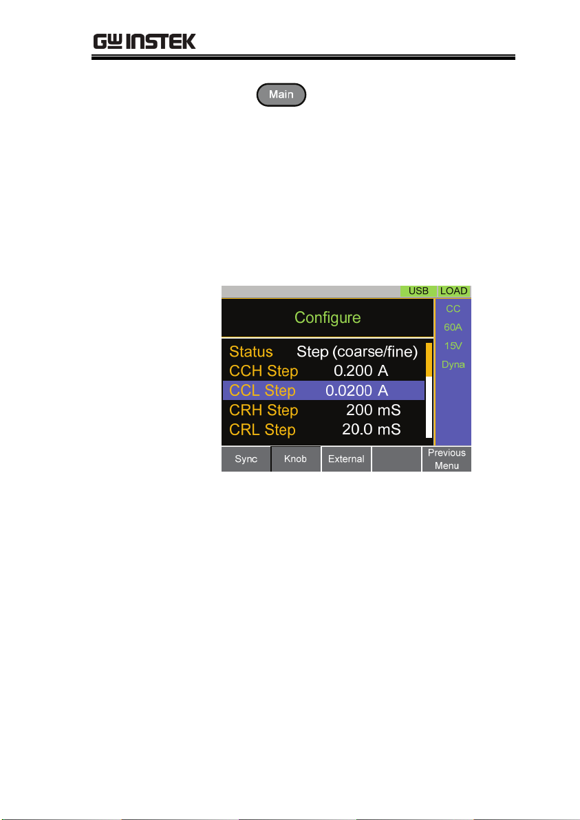
Step Mode Configuration
Description
When set to Step Mode, the voltage, current,
resistance and power settings can have the
step resolution configured. The step resolution
refers to the step resolution of the coarse
adjustment for these settings. The fine
adjustment cannot be configured.
See the Conventions section on page 29 for
details on how to switch between coarse and
fine adjustment modes.
Settings
The step resolution of each setting is
configured separately for each current range.
Settings
CCH Step
CCL Step
CRH Step
CRL Step
CVH Step
CVL Step
CPH Step
CPL Step
Description
CC mode, IRan
CC mode, IRan
CR mode, Ran
CR mode, Ran
CV mode, VRan
CV mode, VRan
CP mode, IRan
CP mode, IRan
e = Hi
e = Low
e = Hi
e = Low
e = Hi
e = Low
e = Hi
e = Low
70
Page 73
OPERATION
Operation
Display
1. Press
> Configure[F5] > Next Menu[F4]
> Knob[F2] and make sure the Status setting is
set to Step.
2. Set the desired step resolution settings. (The
step resolution settings are only available
when Status=Step (coarse/fine))
For example if the step resolution for CCH Step
is 0.200A, then the resolution can be
incremented in 0.2A steps.
71
Page 74

PEL-3000E Series User Manual
g
Protection Settings
The Protection settings are used to prevent damage to the unit or
the DUT by excessive current, voltage or power.
An alarm is generated and a message is displayed on the screen
when a protection setting is tripped. When an alarm is activated,
the load is turned off (or limited), and the ALARM STATUS pin of
the J1 connector on the rear panel (pin 16) turns on (open collector
output by a photocoupler). The protection settings can be used
regardless of whether the remote sense connections are used or not.
OCP
Description
Operation
Alarm
For OCP, the PEL-3000E can be configured to
either limit the current or turn off the load.
The OCP levels can be set to 5% higher than
the rating current.
1. Press
> Configure[F5] > Protection[F1]
and set the OCP Level and OCP Setting.
Range:
OCP Level: Ratin
current + 5%
OCP Setting: LIMIT, Load Off, OFF
When OCP Setting is configured to Load Off, a
message will be displayed on the screen when
OCP is tripped. The Enter key must be pressed
to clear the alarm message.
When configured to LIMIT, OCP will be
displayed on the screen when the OCP is
tripped and the current will be limited to the
OCP Level setting.
When configured to OFF, a message will be
displayed on the screen when ROCP is tripped.
The Enter key must be pressed to clear the
alarm message. When configured to OFF, the
72
Page 75

Display
g
OPP
OPERATION
OCP level is automatically fixed (not
adjustable) as the rating current + 10% of the
currently selected range. For example: If I
Range = Low (6A), then OCP level = 6.6A. This
setting applies to CC, CV and CP modes.
Description
For OPP, the PEL-3031E can be configured to
either limit the power or turn off the load.
The OPP levels can be set to 5% higher than the
rating power.
Operation
1. Press
> Configure[F5] > Protection[F1]
and set the OPP Level and OPP Setting.
Range:
OPP Level: Ratin
power + 5%
OPP Setting: LIMIT, Load Off, OFF
73
Page 76

PEL-3000E Series User Manual
Alarm
Display
When OPP Setting is configured to Load Off, a
message will be displayed on the screen when
OPP is tripped. The Enter key must be pressed
to clear the alarm message.
When configured to LIMIT, OPP will be
displayed on the screen when the OPP is
tripped and the power will be limited to the
OPP Level setting.
When configured to OFF, a message will be
displayed on the screen when ROPP is tripped.
The Enter key must be pressed to clear the
alarm message. When configured to OFF, the
OPP level is automatically fixed (not adjustable)
as the rating power + 10%.
74
Page 77

UVP
OPERATION
Description
Operation
Alarm
Display
If the UVP is tripped, the PEL-3031E will turn
off the load.
The UVP levels can be set from 0V to 2%
higher than the rating voltage.
1. Press
> Configure[F5] > Protection[F1]
and set the UVP Level.
Range:
UVP Level: OFF, 0-Rating voltage +
2%
The UVP indicator and a message will only
appear on the screen when the input voltage is
below the UVP level. The Enter key must be
pressed to clear the alarm message.
To clear the UVP indicator, remove the cause of
the under voltage - i.e., increase the input
voltage.
75
Page 78

OVP
PEL-3000E Series User Manual
Description
Operation
Alarm
Display
If the OVP is tripped, the PEL-3000E will turn
off the load.
The OVP levels can be set from 0V to 5%
higher than the rating voltage.
1. Press
> Configure[F5] > Protection[F1]
and set the OVP Level.
Range:
OVP Level: OFF, 0-Rating voltage +
5%
Note: To turn OVP off, set the OVP voltage
greater than the current rating voltage + 5%.
The OVP indicator and a message will only
appear on the screen when the input voltage is
below the UVP level. The Enter key must be
pressed to clear the alarm message.
To clear the OVP indicator, remove the cause of
the over voltage - i.e., reduce the input voltage.
76
Page 79

UnReg
OPERATION
Description
Alarm
Display
The UnReg error message will appear on the
display when the electronic load is operating
in an unregulated state.
The UnReg indicator will appear on the display
when the set load is inadequate for the source.
To clear the UnReg indicator, increase the
source or reduce the load requirements.
77
Page 80

PEL-3000E Series User Manual
System Settings
The following section covers a number or miscellaneous system
settings such as:
Speaker settings
Display settings
Alarm tone settings
Input control settings
Language settings
All system settings are accessible in the Utility menu.
Sound Settings
Speaker Settings
Description
Operation
78
Turns the speaker sound on or off for the user
interface, such as key press tones and scrolling
tones.
1. Press
+
> Other[F5].
2. Set the Speaker settings on or off.
When set to OFF, the speaker setting will not
disable the tones for Go-NoGo or protection
alarms.
Page 81

OPERATION
Alarm Tone Settings
Description
The alarm tone for the unit can be turned on or
off in the utility menu. The alarm tone can be
set separately for the protection settings (OCP,
OPP, UVP, OVP), Go-NoGo testing or for
when the unit is operating in an unregulated
state (see page 77).
Operation
1. Press
2. Set the alarm tone settings on or off.
The alarm tone settings ignore the Speaker
setting.
Alarm Tone:
UnReg Tone:
Go_NoGo Tone:
Display Settings
Contrast and Brightness
Description
Sets the contrast level.
+
ON, OFF
ON, OFF
ON, OFF
> Other[F5].
Operation
1. Press
+
> Other[F5].
2. Set the Contrast and Brightness settings.
Range:
Contrast: 3 - 13 (low - high)
Brightness: 50 - 90 (low - high)
79
Page 82

PEL-3000E Series User Manual
y
g
h
Control Settings
Description
Operation
1. Press
2. Set the Knob type and Slave knob settings.
Language Settings
Description
The Knob Type setting determines if values
are updated immediately as they are edited or
if they are only updated after the Enter key is
pressed.
The Updated setting is applicable for when the
load is already on and the user wishes to
change the set values (current, voltage, etc.) in
realtime.
The Old setting will only update the values
after the Enter key is pressed.
> Other[F5].
Range:
Knob t
+
pe: Updated, Old
The PEL-3031E supports only English.
Operation
1. Press
+
> Other[F5].
2. Set the Language setting.
80
Supported languages:
En
lis
Page 83

OPERATION
g
Go-NoGo
The Go-NoGo configuration is used to create pass/fail limits on the
voltage or current input. If the voltage/current exceeds the
pass/fail limits, an alarm will be output.
The Go-NoGo configuration can be used with the Program function
to create complex pass/fail tests.
Setting the Go-NoGo Limits
Description
Operation
The Go-NoGo setting limits can be set as either
discrete high & low values or as a percentage
offset from a center value.
1. Press
2. Select Entry Mode and choose how to set the
pass/fail limits.
Value will allow you to set the limits as discrete
values.
Percent will allow you to set the limits as a
percentage offset from a center value.
3. If Entry Mode was set to Value, Set the High &
Low limit values.
High:
Low:
4. If Entry Mode was set to Percent, Set the Center
voltage/current and High, Low % values.
Center:
High:
Low:
> Configure[F5] > Go-NoGo[F3].
0-ratin
0 -rating current/voltage
0-rating current/voltage
0-100% of center voltage/current
0-100% of center voltage/current
current/voltage
81
Page 84

PEL-3000E Series User Manual
5. Set the Delay Time.
The delay time setting will delay activating the
Go-NoGo testing by a specified amount of time.
The delay setting can compensate for startup
oscillation and other instabilities during
startup.
Delay Time
When the Main settings are saved or recalled, the
Note
Go-NoGo settings are also saved/recalled. See the
Save/Recall chapter for details, page 112.
Running a Go-NoGo Test
Description
Operation
Go-NoGo test results are displayed in the
measurement panel.
GO indicates pass (good).
NG indicates fail (no good).
1. Press
0.0-1.0 seconds (0.1s resolution )
> Configure[F5] > Go-NoGo[F3].
2. Set SPEC Test to ON.
When SPEC Test is ON, SPEC will appear in
the Operation Status Panel. This means the unit
is ready for Go-NoGo testing.
3. Turn the load on.
The test starts from the time the load was
turned on + the Delay Time.
82
Page 85

OPERATION
Display:
GO
Display:
NG
Test result
SPEC test = ON
Level1 1.000
Test result
SPEC test = ON
Level1 1.000
LOADUSB
A
A
SPEC
LOADUSB
SPEC
83
Page 86

PEL-3000E Series User Manual
Program
The PEL-3000E can create programs that are designed to stepthrough up to 16 pre-set load operations. The program function is a
powerful tool that can allow you to perform a number of different
operations in succession.
The execution time of each step is user-defined.
Programs can be chained together to make larger programs.
Up to 16 programs can be created for a program chain.
See page 112 for saving load operations.
Program Overview
Description
84
When you run a program, you are essentially
executing up to 16 different load operations
consecutively. Each of the different load
operations are “steps” in the program. A
program starts at step 01 and ends at step 16.
A program recalls the operating mode, range,
static/dynamic mode, response speed and
other settings of each step from stored memory.
It also recalls the Go-NoGo settings.
The same memory settings can be used for
multiple steps.
The execution time of each step is configurable.
Applies the Go-NoGo settings for each step.
Each step must be executed in order.
Each step can be configured to automatically go
to the next step or wait for confirmation from
the user before proceeding to the next step.
Individual steps can be skipped.
Programs can be linked together to make
Page 87

OPERATION
program chains.
Program chains need not be executed in order.
There are 16 steps to a program.
There are up to 16 programs to a chain.
STEP 01
PROGRAM 1
STEP 02
:
STEP 16
STEP 01
PROGRAM 2
STEP 02
:
STEP 16
STEP 01
PROGRAM 3
STEP 02
:
STEP 16
Setting Overview
A program contains the following settings for
each step:
Memory: the memory location of the load
operation for the selected step (M001-M256).
Run: Designates the run setting for the step
(Auto, Manual, Skip).
On-Time: Sets the run time of the test.
Off-Time: Sets the off time between steps.
P/F-Time: Sets the testing pass/fail delay time
for GoNo Go testing.
Short-Time: Sets the shorting time for the step,
if any.
85
Page 88

PEL-3000E Series User Manual
Timing Diagram
for Single Step
P/F Start Test Time (fixed)
Below is a timing diagram of a single step in a
program.
P/F End Test Time (fixed)
0.06s
P/F Time
0.04s
Short-Time
Start of Step End of Step
On-Time Off-Time
Step test time
Create a Program
Note
Program Setting
Display Overview
Before creating a program, the settings for each
step must first be created and saved to internal
memory (M001-M256). See the save recall
chapter for further details, page 112.
86
Page 89

OPERATION
Operation
1. Press
Note that Program[F1] is off by default.
> Program[F1].
2. Select PROG and select a program number to
edit.
PROG
01 -
16
3. Select a STEP in the selected program.
STEP
01 -
16
4. Select Memory and select which memory
location to load for the selected step.
Settings loaded from the memory location will
be used for the selected step.
The same memory location can be used for
multiple steps.
Memory
M001 - M256
5. Set the Run setting for the step.
By default RUN is set to Skip.
The Auto setting will automatically start and
go onto the next step.
The Manual setting will wait for the user to
press Next[F2] before running the step.
Run
Skip, Auto, Manual
6. Choose the On-Time in seconds.
The on-time setting determines how long the
load is turned on for the selected step.
The on-time is defined as the total test time
minus the off-time.
On-Time
0.1 -
60 seconds
87
Page 90

PEL-3000E Series User Manual
-
-
7. Choose the Off-Time in seconds.
The off-time setting determines how long the
load is turned off between the end of the
current step and the start of the next step.
The off-time is defined as the total test time
minus the on-time.
Off-Time
Off, 0.1 -
60 seconds
8. Choose the P/F-Time (pass/fail time) in
seconds.
The P/F-Time refers to the P/F delay time.
This delay time includes the 0.06 P/F start test
time, as shown in the timing diagram on page
86.
P/F-Time
Off, 0.0
119.9 seconds
9. Set the Short-Time in seconds.
Has the same action as pressing the short key.
See page 50 for details about shorting the load.
Short-Time
Off, 0.1 seconds
On-Time
10. Repeat steps 3 to 9 for all the steps in the
program.
A maximum of 16 steps per program can be
created.
Steps that are not configured are set to “Skip”
by default.
11. Press Save[F3] to save the program and all the
steps in the program.
The program will be saved to internal memory.
See the Save/Recall chapter on details on how
to save to Setup memory.
88
Page 91

OPERATION
Recall Default
Pressing Recall Default[F4] will recall the
default settings for each program/step. See
page 217 for details.
89
Page 92

PEL-3000E Series User Manual
Create a Program Chain
Note
Chain Setting
Display Overview
Operation
Before creating a program chain, make sure a
number of programs have already been saved.
These will be used to create the program chain.
1. Press
It may be necessary to load the programs from
> Program[F1] > Chain[F1].
Setup memory if they were not created in the
current session.
2. If Start is not already selected, press Select
Start[F1] and select which program will be
used to start the program chain.
Start:
P01 -
P16
3. Select P01 and choose which program will be
linked to P01.
Selecting OFF will end the chain after P01.
Selecting P01 will create an infinite chain.
Chains need not be linked in sequential order.
90
P01:
OFF, P01 -
P16
Page 93

OPERATION
4. Repeat step 3 for any remaining programs in
the chain.
5. Press Save to save the program chain to
internal memory.
Pressing Recall Default[F4] will reset the chain
to the default settings. See page 217 for details.
Recall Default[F4] will essentially clear the
program chain.
Running a Program or Chain
Description
Operation
A program or program chain is run the same
way as a normal load.
1. Press
2. Turn program mode on by setting Program[F1]
to On.
will appear at the top of the display when
Program is On.
> Program[F1].
3. Turn the load on.
The program/chain starts immediately.
The icon turns orange when the load is
turned on.
4. When a program/chain is running the screen
displays which program, step and memory is
currently active.
Press Pause[F1] to suspend a test, press
Continue[F1] to resume.
Press Next[F2] to run the next step if its Run
setting was set to Manual.
91
Page 94

Display:
Program/Chain
Running
Display:
Program/Chain
Finished
PEL-3000E Series User Manual
5. When a program/chain has finished running, a
list of the Go-NoGo results for each step are
displayed.
Press Exit[F5] to exit.
92
Page 95

OPERATION
Sequence
The PEL-3000E supports both programs and sequences. The
essential difference between programs and sequences is that
programs can use different operating modes for each step while
sequences use the same operating mode throughout the whole
sequence. In effect sequences are used to create complex load
simulations.
There are two different types of Sequences, Normal Sequences and
Fast Sequences.
Normal sequences can define the execution time and slew rate of
each step.
On the other hand the execution time for each step in a fast
sequence is fixed to the rate (Time Base setting) set by the user.
Normal Sequence Overview
Description
A normal sequence is comprised of a userdefined number of steps that when executed in
sequence can be used to simulate a DC load.
Up to 1000 discrete steps can be configured
using normal sequences.
Each normal sequence can have a memo note
attached to it.
Normal Sequences can be looped up to 9999
discrete times or for an infinite amount of
times.
Normal sequences can be configured to hold a
set voltage, current, power or resistance at the
end of the load.
Normal Sequences can be linked together in a
chain.
93
Page 96

PEL-3000E Series User Manual
Description
Normal Sequence configuration is split into
Timing Edit configuration and Data Edit
configuration.
Timing Edit configuration is used to configure
the actual sequences, such as mode, range,
loops and chains.
Data Edit configuration is used to create the
actual steps used in each sequence.
See below for a description of each.
Timing Edit
Overview
A Normal Sequence contains the following
timing settings for each sequence:
Setting Setting Range Description
Start S01 - S10
Sets which sequence is used
to start a chain of Normal
Sequences.
Seq.No S01 - S10
Sets the current sequence to
edit.
94
Page 97

OPERATION
Memo 12 characters
A user-created note for the
currently selected sequence.
Mode CC, CR, CV, CP
Operating mode for the
sequence. +CV mode is
supported.
Range ILVL
IHVL
ILVH
IHVH
SLVH
SHVL
Loop Infinite,
01 - 9999
Last Load OFF, ON
Low I range, low V range
High I range, low V range
Low I range, high V range
High I range, high V range
Low S range, high V range
High S range, low V range
Sets the amount of times to
loop the selected sequence.
Set the load condition after
the end of the sequence.
Not available when
Loop=Infinite.
Last Value
The setting value of the
load for when Last Load =
ON. Not available when
Loop=Infinite.
Chain Off, S01-S10
Sets the next sequence in
the chain, when not set to
off. Not available when
Loop=Infinite.
Data Edit
Overview
Each step in a normal sequence contains the
following setting parameters:
Setting Setting Range Description
Step 0001 - 1000
Selects/displays the current
step in the sequence.
The number of available
steps is dependent on the
number of steps added
using the Insert Point[F1]
functions.
95
Page 98

PEL-3000E Series User Manual
n
Value
The current, voltage, power
or resistance setting for the
selected operating mode.
Load ON, OFF
Turns the load on or off for
the selected step.
RAMP ON, OFF
When turned on the current
transition is evenly ramped
from the start of the step to
the end of the step. When
turned off the current
transition is stepped.
Ramp = O
amplitude
Step time
Ramp = Off
amplitude
Time
Time
Step time
TRIG OUT ON, OFF
When TRIG OUT is set to
ON, a trigger signal is
output from the TRIG OUT
BNC terminal at the start of
the step. See page 65, 199
for details.
TRIG OUT = ON
amplitude
Time
Start of step
TRIG OUT
96
Page 99

OPERATION
PAUSE ON, OFF
Pause: Inserts a pause at the
end of the step. When
paused, the unit will pause
at the end of the step
current/voltage/resistance
/power level. The sequence
can be resumed by pressing
Next[F2] or by using the
TRIG IN BNC terminal
(page 199).
97
Page 100

PEL-3000E Series User Manual
Timing Edit Configuration
Edit Timing
Display
Operation
98
1. Press
> Sequence[F2] > Normal
Sequence[F1].
Note that N. Seq.[F1] is off by default.
2. Select Start and select the number of the
starting sequence.
Start:
S01 -
S10
3. Select a Seq. No. and select which sequence to
edit.
Seq. No.:
S01 -
S10
4. Set the following parameters for the currently
selected sequence. See page 93 for details on
each parameter.
Memo
Mode
Range
Loop
 Loading...