

Page 1

PEL-3000H
Page 2

Page 3
PEL-3000 Series Parallel Assembly Guide
1
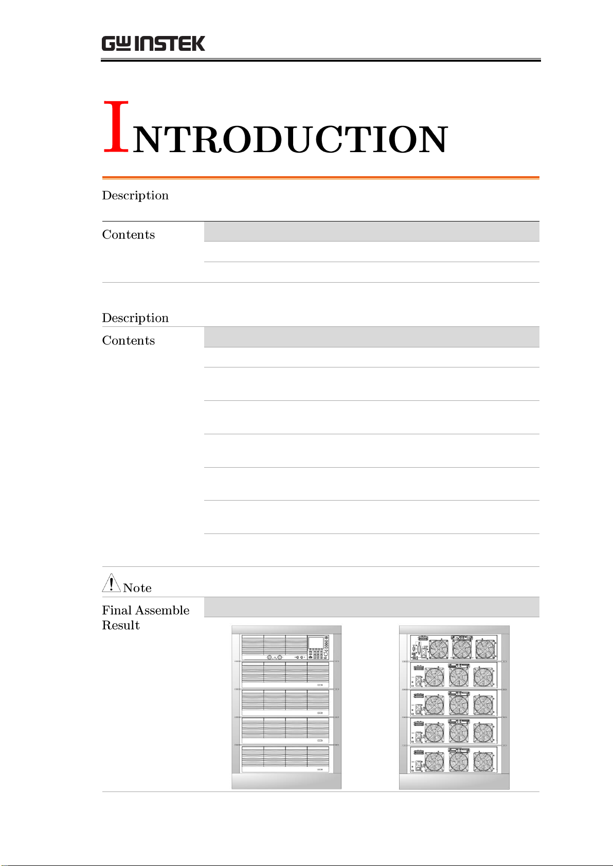
PEL-3000H Parallel to 9KW contains the parts below
(i.e., PEL-3955H with outline Rack)
Model Name
Part Number
Quantity
Description
PEL-3111H
01EL311H00GT
1
1KW LOAD Master
PEL-3211H
01EL321H00GT
4
2KW LOAD Booster
Connection & Structure Accessory
Model Name
Part Number
Quantity
Description
PEL-005
11EL-00500101
1
Bus Bar Connector
PEL-006
11EL-00600101
1
Bus Bar Connector
(Included PEL-005)
PEL-007
11EL-00700101
1
Bus Bar Connector
(Included PEL-005)
PEL-008
11EL-00800101
1
Bus Bar Connector
(Included PEL-005)
PEL-009
11EL-00900101
1
Bus Bar Connector
(Included PEL-005)
GRA-413-E
01RA4130000GT
4
PEL-3111 3U Frame
(Optional)
GRA-414-E
01RA414E000GT
1
PEL-3111 3U Frame
(Optional)
Refer to the PEL-3000H Series Rack Parts details_EN.doc for the other models.
Front View
Rear View
Page 4
PEL-3000 Series Parallel Assembly Guide
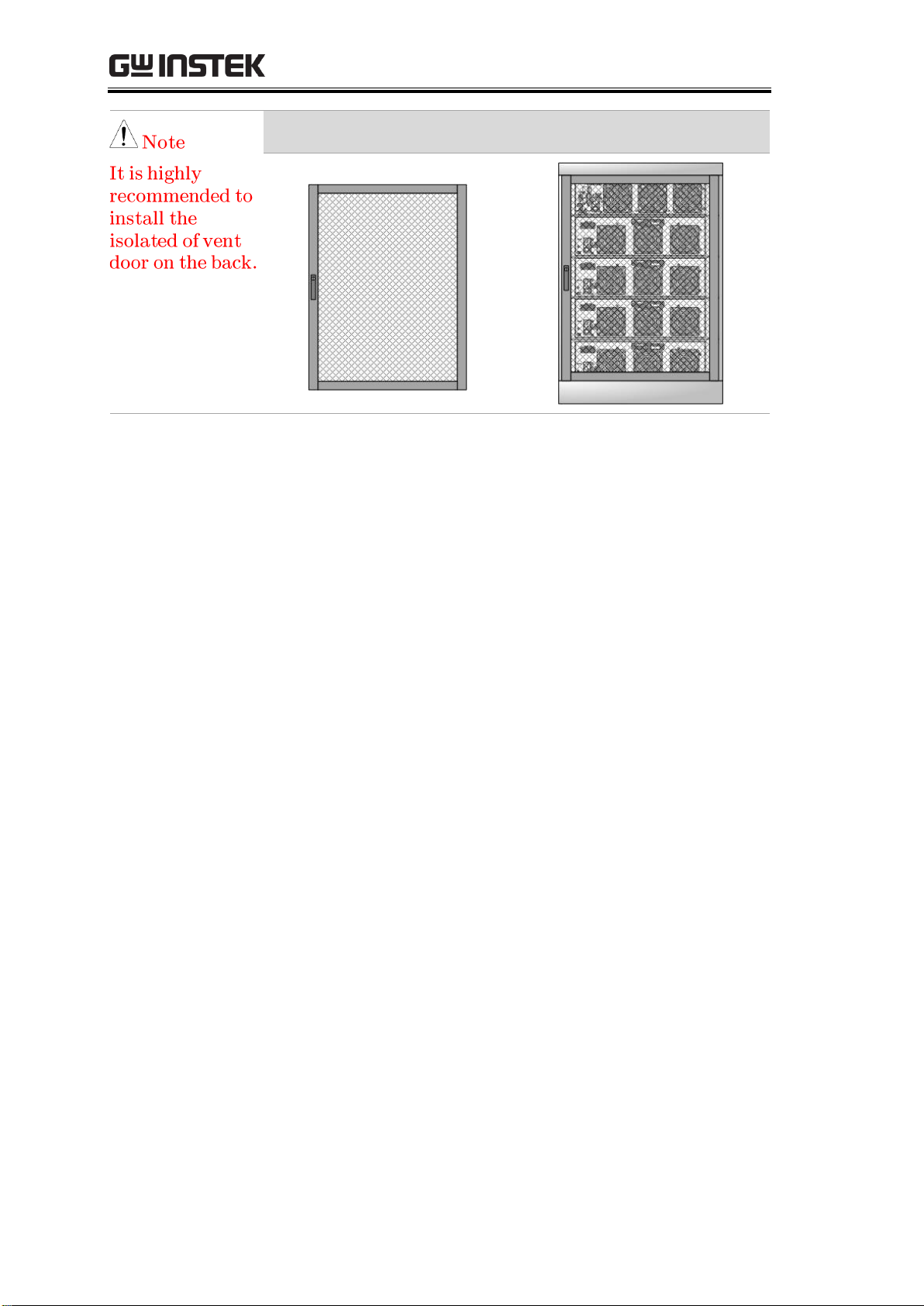
2
Isolated ventilation door
Rear View with
Isolated ventilation door
Page 5
PEL-3000 Series Parallel Assembly Guide
3
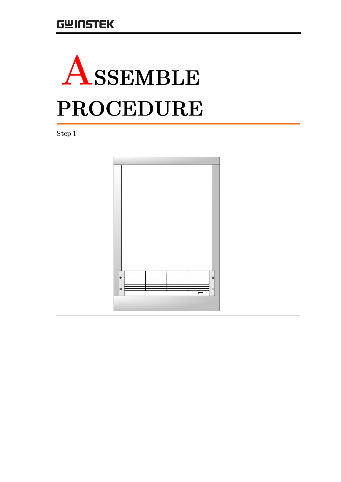
Put the 1st PEL-3211H on the bottom of the rack followed by fastening
the 4 screws for side bracket in the front but not tightening them
completely.
Page 6

PEL-3000 Series Parallel Assembly Guide
4
Screw the L-shape brackets in the interior side of rack. An approx. 1mm
distance between the bottom of brackets and the top of PEL-3211H is
required.
Put the 2nd PEL-3211H onto the L-shape brackets within the rack and,
again, fasten the 4 screws for side bracket in the front but not tighten
them fully followed by screwing another group of L-shape brackets
within the interior of rack.
2nd unit installation completion
L-shape
bracket
The L-shape brackets screwed
on the interior side of rack
Approx. 1mm between
bracket and the top of unit
Page 7

PEL-3000 Series Parallel Assembly Guide
5
Repeat the previous steps in order to install the rest of PEL-3211Hs and
further install the bracket (GRA-414-3) of PEL-3111H on the upper side
followed by installing the PEL-3111H onto the top of the bracket.
Assembly completion for 5 units
Page 8

PEL-3000 Series Parallel Assembly Guide
6
Assemble the L-type copper stick (PEL-005) onto the output terminal in
the rear side of each unit as the figure below shown.
L-type copper stick assembly
L-type copper sticks assembly completion
In accordance with the figure below, assemble the copper sticks for unit
conjunction followed by fastening the screws in the front of rack tightly.
Copper sticks assembly diagram
Diagram of rear side for copper
sticks assembly
Page 9

PEL-3000 Series Parallel Assembly Guide
7
Page 10

PEL-3000 Series Parallel Assembly Guide
8
Install the parallel cables in accord with the following figure.
The last cable connecting to the last unit cannot be clipped with core. When
only one PEL-3111H connects to a PEL-3211H (Booster) in parallel, the cable
in the Booster end cannot be clipped with core.
Page 11

PEL-3000 Series Parallel Assembly Guide
9
Refer to the figure below; connect the AC power cords for all units to the
power sockets in the rear side individually followed by powering on the
power switch that is underneath the power socket (─ indicates power ON).
Attentively check if the indicator in the front panel of all units lights up
with red color:
I. Master indicator lights up as the figure below:
II. Booster indicator lights up as the figure below (STBY indicator
lights up):
Page 12

PEL-3000 Series Parallel Assembly Guide
10
Power on the power switch in the Master front panel and the indicator
lights up in green as figure below shown:
Press
Main
> Configure[F5] > Next Manu[F4] in the front panel
followed by selecting “4” for Booster number within Configure page,
which indicates 4 Booster units in parallel. See the steps figures below:
Select Booster number corresponding to the actual Booster number in parallel.
Page 13

PEL-3000 Series Parallel Assembly Guide
11
Properly confirm if the indicator in the front panel of all PEL-3211H
(Booster) lights up with LINK in green, which means the software setting
connects to Booster appropriately. Refer to the figure below.
Page 14

PEL-3000 Series Parallel Assembly Guide
12
The current sink power of PEL-3111H and PEL-3211H is 1KW:2KW;
therefore, the ratio of current sink will always be the exactly 1:2.
E.g., PEL-3322H (3KW); when current sink is set 30A, Master (PEL-3111H)
will sink current by 10A, whilst Booster (PEL-3211H) will sink current by
20A.
E.g., PEL-3955H (9KW); when current sink is set 90A, Master
(PEL-3111H) will sink current by 10A, whilst the rest of the 4 Booster
(PEL-3211H) will sink current by 20A individually.
First dismantle all of the positive parallel copper sticks and parallel cables
in the rear output terminal of unit.
Check the 1st Booster current:
I. Connect the parallel cable to the J2 connector in the rear of
PEL-3111H in one end and the J1 connector in the rear of
PEL-3211H in the other end.
II. Power on both PEL-3111H and the 1st PEL-3211H, while keep
the rest units power-off. Set the unit PEL-3111H as the parallel
mode via the following procedure:
III. Select from the main interface
a. Configure > Next Menu > Parallel > Operation; select: Master
b. Configure > Next Menu > Parallel > Parallel; select: OFF
c. Configure > Next Menu > Parallel > Booster; select: 1
Page 15

PEL-3000 Series Parallel Assembly Guide
13
IV. Based on the connection method in the figure below, connect
current sink cable to the unit followed by setting current sink
value for unit. Measure the currents from both the current sink
cable of Master positive pole and the current sink cable of Booster
positive pole, via current probe, to validate the accuracy of
currents. The measured current value of Master is supposed to be
1/3 of the set value, whereas the measured current value of
Booster should be 2/3 of the set value.
Page 16

PEL-3000 Series Parallel Assembly Guide
14
The 2nd Booster current checkup:
I. Connect the parallel cable to the J2 connector in the rear of
PEL-3111H in one end and the J1 connector in the rear of
PEL-3211H in the other end.
II. Power on both PEL-3111H and the 2nd PEL-3211H, while keep
the rest units power-off. Set the unit PEL-3111H as the parallel
mode. The setting procedure is identical to the setting of the 1st
PEL-3211H validation.
III. Based on the connection method in the figure below, connect
current sink cable to the unit followed by setting current sink
value for unit. Measure the currents from both the current sink
cable of Master positive pole and the current sink cable of Booster
positive pole, via current probe, to validate the accuracy of
currents. The measured current value of Master is supposed to be
1/3 of the set value, whereas the measured current value of
Booster should be 2/3 of the set value.
Follow the previous steps to validate the 3rd and the 4th Booster
respectively.
The assembly procedure and system setting are completely finished.
Press
Main
to return back to the main screen and the current sink test
is properly ready to initiate.
 Loading...