

Page 1

3.0GHz Spectrum Analyzer
GSP-830
USER MANUAL
GW INSTEK PART NO. 82SP-83000MA1
ISO-9001 CERTIFIED MANUFACTURER
Page 2

This manual contains proprietary information, which is protected by
copyrights. All rights are reserved. No part of this manual may be
photocopied, reproduced or translated to another language without
prior written consent of Good Will company.
The information in this manual was correct at the time of printing.
However, Good Will continues to improve products and reserves
the rights to change specification, equipment, and maintenance
procedures at any time without notice.
Windows is a registered trademark of Microsoft Corporation in the United States and other countries.
Good Will Instrument Co., Ltd.
No. 7-1, Jhongsing Rd., Tucheng City, Taipei County 236, Taiwan.
Page 3

Table of Contents
Table of Contents
SAFETY INSTRUCTIONS ....................................................6
Safety Symbols ....................................................6
Safety Guidelines ................................................6
GETTING STARTED............................................................9
GSP-830 Characteristics.................................... 10
Package Contents.............................................. 11
Front Panel Overview ........................................ 13
Rear Panel Overview ......................................... 16
Display Overview .............................................. 18
Tilt Stand & Power Up ...................................... 20
Error Check .......................................................22
Functionality Check........................................... 23
QUICK REFERENCE..........................................................25
Operation Shortcuts ......................................... 26
Menu Tree ......................................................... 31
Preset Contents................................................. 40
FREQUENCY/SPAN..........................................................41
View Signal (Center and Span).......................... 42
View Signal (Start and Stop)............................. 44
Full/Zero Span .................................................. 46
Recall the Last Span Setting.............................. 47
AMPLITUDE .....................................................................48
Set Vertical Scale............................................... 49
Amplitude Correction........................................ 52
Use Pre-Amplifier (Optional) ............................ 56
Set Input Impedance......................................... 57
AUTOSET .........................................................................58
How Autoset Works ..........................................59
Run Autoset ......................................................60
Limit vertical search range................................ 61
Limit horizontal view range............................... 61
MARKER ...........................................................................62
Activate/de-activate marker .............................. 63
Move marker ..................................................... 65
Show Markers in Table ...................................... 67
3
Page 4

GSP-830 User Manual
PEAK SEARCH ................................................................. 68
Search Signal Peak ............................................ 69
Show Peak Table................................................71
TRACE ............................................................................. 73
View traced waveform ....................................... 74
Move Marker to Trace ....................................... 76
Run Trace Math .................................................78
Select Signal Detection Mode ........................... 80
POWER MEASUREMENT................................................. 82
ACPR Measurement ..........................................83
OCBW Measurement.........................................86
N dB Measurement ...........................................88
Phase Jitter Measurement .................................89
LIMIT LINE...................................................................... 90
Edit Limit Line................................................... 91
Run Pass/Fail test ............................................. 94
BANDWIDTH .................................................................. 95
Select RBW (Resolution BandWidth) ................96
Select VBW (Video BandWidth) ........................98
RBW/VBW Auto Mode Contents .......................99
Set Sweep time................................................ 101
Average Waveform........................................... 101
TRIGGER ........................................................................103
Select Trigger Type ..........................................104
Select Trigger Mode ........................................105
Set Trigger Delay ............................................. 106
DISPLAY .........................................................................107
Change Display Brightness ............................. 108
Activate Display Line....................................... 108
Enter Display Title........................................... 109
Use Split Display............................................. 110
Use VGA Output ............................................. 111
Save Display Image to USB Flash Drive .......... 111
FILE ................................................................................113
File Location and File Type..............................114
Copy File .........................................................115
Delete File....................................................... 118
Rename File .................................................... 120
4
Page 5

Table of Contents
Save Display Image to USB Flash Drive .......... 121
PRESET...........................................................................123
SYSTEM..........................................................................124
Save/Recall Panel Setting ............................... 125
Configure Communication Interface ............... 126
View System Information ................................ 128
Set Date/Time................................................. 132
Synchronize GSP-830 with Other Devices ....... 133
Select Language .............................................. 135
Use Auxiliary Signal ........................................ 135
Enter Service Operation .................................. 135
SEQUENCE ....................................................................136
Edit Sequence ................................................. 137
Run Sequence ................................................. 140
TRACKING GENERATOR ................................................142
DEMODULATOR ............................................................144
EMI FILTER.....................................................................146
BATTERY / DC OPERATION ...........................................148
Battery Operation............................................ 148
DC Operation.................................................. 149
PC SOFTWARE ...............................................................150
Install Software ............................................... 151
Connect Software ............................................ 152
Use Software ................................................... 154
REMOTE CONTROL .......................................................157
Configure Interface ......................................... 158
Command Syntax ............................................ 160
Command Set ................................................. 161
FAQ................................................................................171
Appendix ........................................................................172
GSP-830 Specifications ................................... 172
Optional Items Specifications......................... 174
Declaration of Conformity............................... 176
INDEX ............................................................................177
5
Page 6
GSP-830 User Manual
SAFETY INSTRUCTIONS
This chapter contains important safety instructions that
you must follow when operating the GSP-830 and when
keeping it in storage. Read the following before operating
this instrument to ensure your safety and to keep the
GSP-830 in best condition.
Safety Symbols
These safety symbols may appear in this manual or on the GSP-830.
Warning: Identifies conditions or practices that could
WARNING
result in injury or loss of life.
Caution: Identifies conditions or practices that could
CAUTION
result in damage to the GSP-830 or to other properties.
DANGER High Voltage
Attention Refer to the Manual
Protective Conductor Terminal
Earth (ground) Terminal
Safety Guidelines
General Guideline
CAUTION
• Make sure that the RF input level and the Tracking
Generator output reversed power level do not exceed
+30dBm.
• Do not supply an input signal to the Tracking Generator
output.
• Do not place any heavy object on the GSP-830.
• Avoid severe impacts or rough handling that leads to
damaging the GSP-830.
• Do not discharge static electricity onto the GSP-830.
6
Page 7
SAFETY INSTRUCTIONS
Power Supply
WARNING
• Use only mating connectors, not bare wires, for the
terminals.
• Do not block or obstruct the cooling fan vent opening.
• Do not perform measurement at a power generating source
or building installation site (Note below).
• Do not disassemble the GSP-830 unless you are technically
qualified.
(Note) EN 61010-1:2001 specifies the measurement categories and
their requirements as follows. The GSP-830 falls under category II.
• Measurement category IV is for measurement performed at the
source of low-voltage installation.
• Measurement category III is for measurement performed in the
building installation.
• Measurement category II is for measurement performed on the
circuits directly connected to the low voltage installation.
• AC Input voltage: 100 to 240 V AC, 50/60Hz, 90W
maximum
• DC Input voltage: 12V DC, 40W maximum
• The power supply voltage should not fluctuate more than
10%.
• Connect the protective grounding conductor of the AC
power cord to an earth ground, to avoid electrical shock.
Battery
CAUTION
Fuse
WARNING
Cleaning the
GSP-830
Operation
Environment
• Rating: 11.1V lithium-ion battery pack x 2
• Turn off the main power switch before installing or taking
out the battery packs.
• Fuse type: T1.6A/ 250V, time-delay, 5x20mm glass
• To ensure fire protection, replace the fuse only with the
specified type and rating.
• Disconnect the power cord before fuse replacement.
• Make sure the cause of fuse blowout is fixed before fuse
replacement.
• Disconnect the power cord before cleaning.
• Use a soft cloth dampened in a solution of mild detergent
and water. Do not spray any liquid into the GSP-830.
• Do not use chemicals or cleaners containing harsh
products such as benzene, toluene, xylene, and acetone.
• Location: indoor, no direct sunlight, dust free, almost
non-conductive pollution (Note below)
• Relative Humidity: < 90%
• Altitude: < 2000m
• Temperature: 18°C to 28°C
Storage
Environment
• Location: indoor
• Relative humidity: < 85%
• Temperature: 0°C to 40°C
7
Page 8
GSP-830 User Manual
(Note) EN 61010-1:2001 specifies the pollution degrees and their
requirements as follows. The GSP-830 falls under degree 2.
Pollution refers to “addition of foreign matter, solid, liquid, or
gaseous (ionized gases), that may produce a reduction of dielectric
strength or surface resistivity”.
• Pollution degree 1: No pollution or only dry, non-conductive pollution
occurs. The pollution has no influence.
• Pollution degree 2: Normally only non-conductive pollution occurs.
Occasionally, however, a temporary conductivity caused by
condensation must be expected.
• Pollution degree 3: Conductive pollution occurs, or dry,
non-conductive pollution occurs which becomes conductive due to
condensation which is expected. In such conditions, equipment is
normally protected against exposure to direct sunlight, precipitation,
and full wind pressure, but neither temperature nor humidity is
controlled.
Power cord for the United Kingdom
When using the GSP-830 in the United Kingdom, make sure the power cord
meets the following safety instructions.
NOTE: This lead / appliance must only be wired by competent persons
WARNING: THIS APPLIANCE MUST BE EARTHED
IMPORTANT: The wires in this lead are coloured in accordance with the following code:
Green/ Yellow: Earth
Blue: Neutral
Brown: Live (Phase)
As the colours of the wires in mains leads may not correspond with the colour markings
identified in your plug/appliance, proceed as follows:
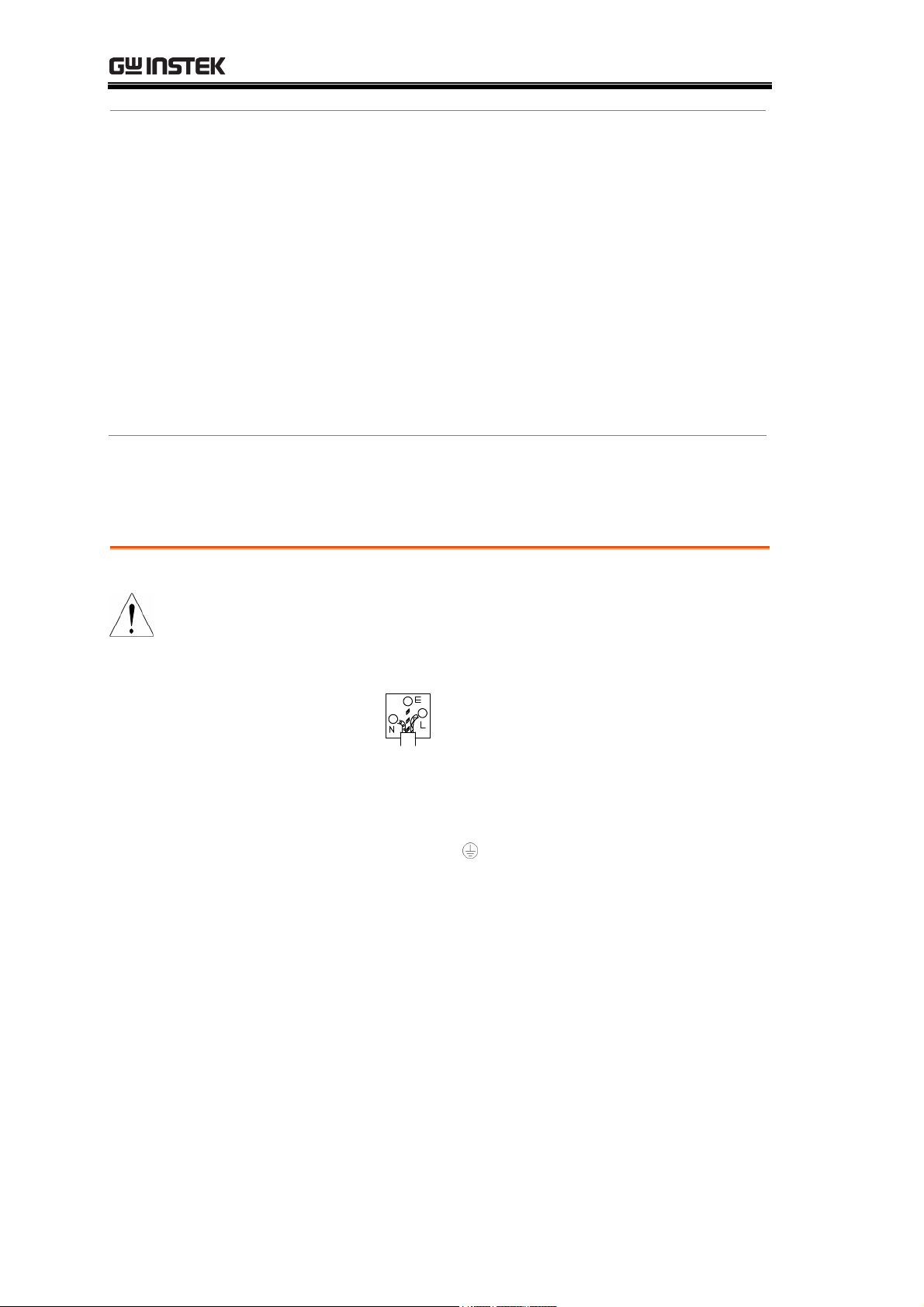
The wire which is coloured Green & Yellow must be connected to the Earth terminal
marked with the letter E or by the earth symbol
or coloured Green or Green & Yellow.
The wire which is coloured Blue must be connected to the terminal which is marked with
the letter N or coloured Blue or Black.
The wire which is coloured Brown must be connected to the terminal marked with the
letter L or P or coloured Brown or Red.
If in doubt, consult the instructions provided with the equipment or contact the supplier.
This cable/appliance should be protected by a suitably rated and approved HBC mains
fuse: refer to the rating information on the equipment and/or user instructions for details.
As a guide, cable of 0.75mm
2
should be protected by a 3A or 5A fuse. Larger conductors
would normally require 13A types, depending on the connection method used.
Any moulded mains connector that requires removal /replacement must be destroyed by
removal of any fuse & fuse carrier and disposed of immediately, as a plug with bared wires
is hazardous if a engaged in live socket. Any re-wiring must be carried out in accordance
with the information detailed on this label.
8
Page 9
GETTING STARTED
GETTING STARTED
This chapter describes the GSP-830 in a nutshell,
including its main features, package contents, and front /
rear / display panel introduction. After going through
the overview, follow the Power-up sequence and
Functionality check section to properly setup the
GSP-830.
GSP-830
package
Panel
introduction
Setup
GSP-830 Characteri
Package Contents...................................................11
Front Panel Overvie
Rear Panel Overview ..............................................16
Display Overview....................................................18
Status Icon overview ..............................................19
Tilt stand................................................................20
Power Up................................................................20
Error Check ............................................................22
Functionality Check ................................................23
stics .........................................10
w .............................................13
9
Page 10

GSP-830 User Manual
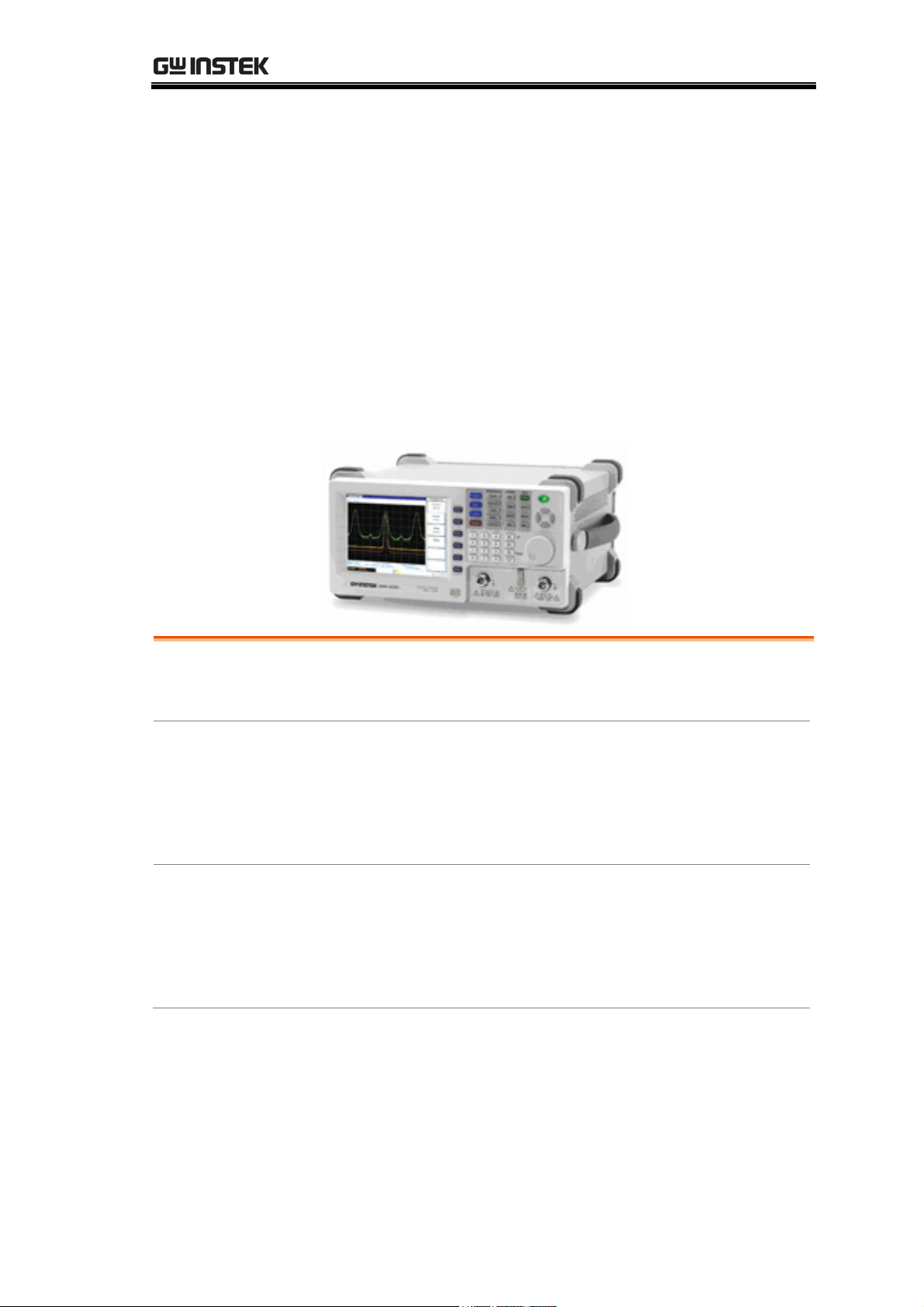
GSP-830 Characteristics
The GSP-830 is a mid-to-high range digital storage
spectrum analyzer suitable for a wide variety of
applications, such as production testing, research, and
field verification.
Performance
• Low noise floor: typical -117dBm @1GHz, 3k RBW
• Fast sweep: 50ms to 25.6s
• Compact size: 330(W) x 170(H) x 340(D) mm
• Light weight: approx. 6kg
Features
Interface
Optional Items
(complete list on
the next page)
• Autoset
• 5 markers with delta marker and peak functions
• 3 traces
• Power measurements: ACPR, OCBW, N-dB, Phase
Jitter
• Pass/fail test with limit line editing
• Split windows with separate settings
• Sequence programming (user-defined macro)
• 6.4 TFT color LCD, 640 x 480 resolution
• Phone output (available in the optional Demodulator)
• AC/DC/battery multi-mode power operation
• USB host for storage device connection
• USB slave/RS232/GPIB(optional) for PC software
connection and remote control
• Direct VGA display image output
• Reference signal input/output for synchronization
• External trigger signal input
• Tracking Generator
• Pre-amplifier GAP-801 (10dB typical, 9kHz to 6GHz)
• Pre-amplifier GAP-802 (20dB typical, 9kHz to 3GHz)
• ±1ppm stability module
• EMI filter with 9kHz/120kHz RBW and 6-dB
bandwidth
• Battery pack
• Demodulator
• 300Hz/10kHz/100kHz RBW
• GPIB interface
10
Page 11
GETTING STARTED
Package Contents
Contact your dealer in case of missing items. The detailed specifications are
listed from page172.
GSP-830
Standard
accessories
• Power cord
• USB cable (Type A to Type B) for PC connection
• User Manual (this document)
Optional items Option01 Tracking Generator (factory installed)
Option02 Battery Pack
Option03 ±1ppm Stability Module (factory installed)
Option04 300Hz RBW (factory installed)
Option05 9kHz & 120kHz RBW (also called EMI Filter,
factory installed)
Option06 10kHz & 100kHz RBW (factory installed)
Option07 Demodulator (factory installed)
Option08 GPIB Interface (factory installed)
Note: Among Option 05, 06, and 07, only one can be
installed at a time.
ADP-001 BNC(J/F) to N(P/M) Adaptor Optional
accessories
ADP-002 SMA(J/F) to N(P/M) Adaptor
ADP-101 BNC(J/F)75Ω to BNC(P/M)50Ω Adaptor
ATA-001 BNC Antenna
ATN-100 10dB Attenuator N(J/F)-N(P/M)
GAK-001 Terminator 50Ω N(P/M)
GAK-002 Cap with Chain N(P/M)
GAP-801 Pre-Amplifier, 9kHz to 6GHz, 10dB typical
GAP-802 Pre-Amplifier, 9kHz to 3GHz, 20dB typical
11
Page 12

GSP-830 User Manual
GKT-001 General Kit Set
ADP-002: SMA (J/F) to N (P/M) Adaptor x 2
ATN-100: 10dB Attenuator x 1
GTL-303:
RF Cable Assembly (RD316, SMA(P),60cm) x2
GSC-002: Kit box
GKT-002 CATV Kit Set
ADP-001: BNC (J/F) to N (P/M) Adaptor x 2
ADP-101: BNC(P/M) 50 to BNC(J/F) 75 adaptor x2
GTL-304:
RF Cable Assembly (RG223,N(P)-N(J),30cm) x2
GSC-003: Kit box
GKT-003 RLB Kit Set
GAK-001: Termination, N(P), 50 x 1
GAK-002: Cap with Chain, N(P) x 1
GTL-302:
RF Cable Assembly (RG223, N(P), 30cm) x2
GSC-004: Kit box
GKT-006 EMI Probe Set
ADP-01: Adaptor, BNC(J/F) - N(P/M) x 1
ADP-02: Adaptor, SMA(J/F) – N(P/M) x 1
ANT-01: 6cm Loop, H-Field Probe x 1
ANT-02: 3cm Loop, H-Field Probe x 1
ANT-03: 6mm Loop, H-Field Probe x 1
PR-03: Touch Passive Probe, < 3GHz x 1
Test Lead: RF Cable Assembly BNC(P/M)-BNC(P/M)x1
Test Lead: RF Cable Assembly SMA(P/M)-SMA(P/M)x1
GRA-404 19 Inch Rack Adaptor Panel, 4U
GSC-001 Soft Carrying Case
GTL-301 RF Cable Assembly, RG223, N(P/M), 1000mm
GTL-302 RF Cable Assembly, RG223, N(P/M), 300mm
GTL-303 RF Cable Assembly, RD316, SMA(P/J), 600mm
GTL-304 RF Cable Assembly, RG223, N(P/M) to N(J/F),
300mm
GTL-401 DC Power Line with Lighter Plug, 5A
RLB-001 Return Loss Bridge
12
Page 13
GETTING STARTED
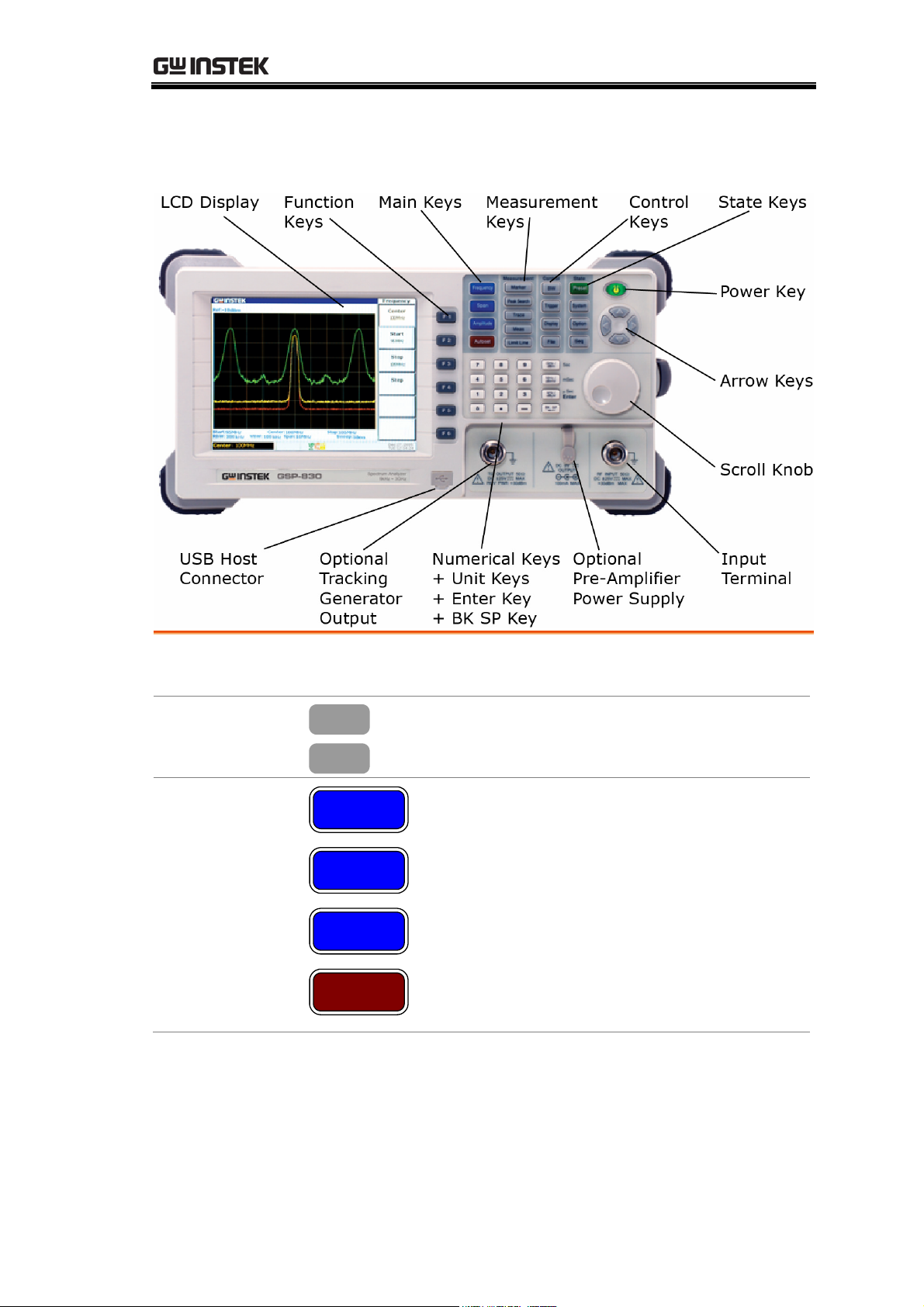
Front Panel Overview
LCD Display
F1 to F6 Function
Keys
Main Keys
TFT Color display, 640x480 resolution. For display setting
details, see page107.
F 1
F 6
Frequency
to
Soft keys linked to the menu that appears
on the right side of the display.
Frequency key (page41), together with
Span k
ey, configures the horizontal
(frequency) scale.
Span
Amplitude
Amplitude key (page48) configures the
ertical (amplitude) scale and input
v
impedance.
Autoset key (page58) automatically
hes the peak signal with maximum
searc
Autoset
amplitude and displays it with appropriate
horizontal and vertical scales.
13
Page 14
GSP-830 User Manual
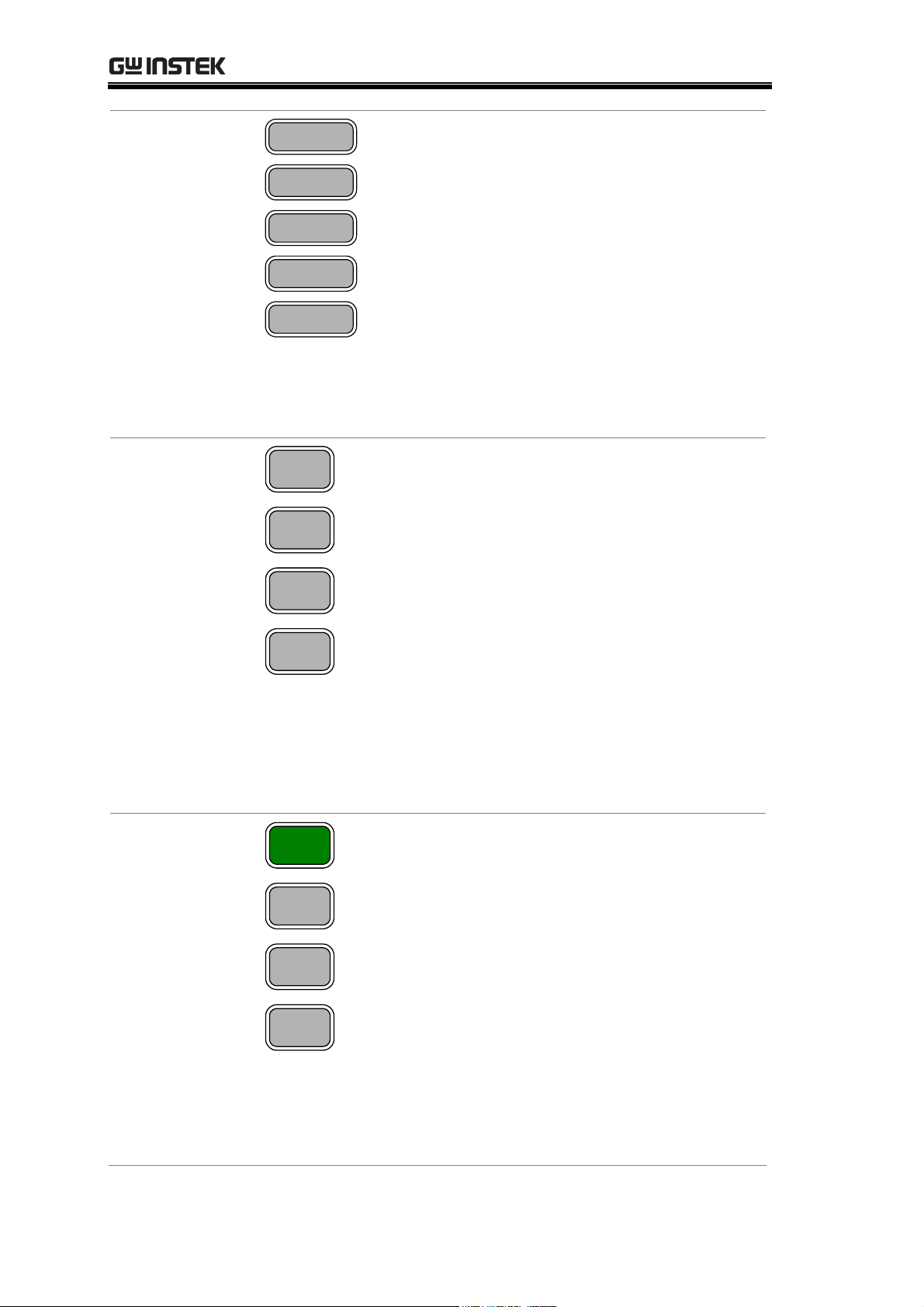
Measurement
keys
Control keys
Marker
Peak Search
Trace
Meas
Limit Line
BW
Trigger
Display
File
Marker key (page62) activates markers
and places them on specified loca
tions.
Peak Search key (page68) searches peak
signals and configures peak rang
es/orders.
Trace key (page73) activates trace signals,
configures them, and r
uns trace math
operations.
Measurement key (page82) configures
uns 4 types of Power Measurements:
and r
ACPR, OCBW, N-dB, and Phase Jitter.
Limit Line key (page90) configures
high/lo
w limit lines and runs the pass/fail
test.
BW key (page95) configures the
RBW/VBW width, sw
eep time length, and
waveform averaging number.
Trigger key (page103) selects the trigger
, sets the trigger running mode / delay
type
/ frequency, and activates the external
trigger input.
Display key (page107) configures the
LCD dim
line and title, and activates split windows.
mer, edits and shows the display
File key (page113) saves/recalls/deletes
the trace w
aveform, limit line, amplitude
correction, sequence, and panel settings.
Display images may be saved to a storage
device via the front panel USB port.
State Keys
14
Preset
System
Option
Seq
Preset key (page40or123) resets the
GSP-830 to a predefined state
.
System key configures the date/time
(page132), GPIB/RS232C interface
e126), and language (page135). It also
(pag
ws the system information (page128)
sho
and self
ves/recalls panel settings (page125).
sa
Option k
Generator (page142), Demodulator
(pag
reference frequency (pag
Seq k
sequences (user
test result (page131), and
ey configures the Tracking
e144), battery (page148), and external
e133).
ey (page136) edits and runs
-defined macro).
Page 15
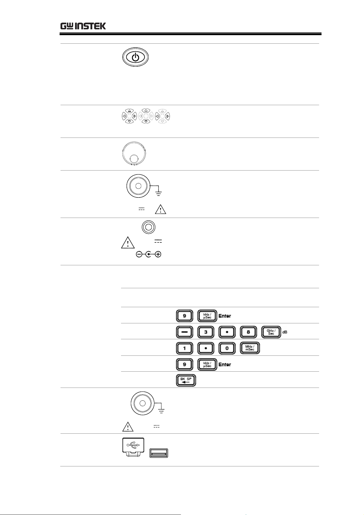
GETTING STARTED
Power Key
Arrow Keys
Scroll Knob
Input Terminal
Pre-Amplifier
Power Supply
Te rmi na l
RF INPUT 50 Ω
DC ±25V
+30dBm MAX
DC 9V
OUTPUT
100mA MAX.
MAX
Power key selects the power state between
the standby mode (Red LED on) and
power on mode (Green LED on). To turn
on/off the main power, use the power
switch on the rear panel. See page20 for
the po
wer up sequence.
Arrow keys select parameters in various
occasions; Up/Right for increasing,
Down/Left for decreasing.
Scroll knob sets or selects parameters in
various occasions. In many cases, it works
in tandem with the Arrow keys.
Input terminal accepts RF input signals.
• Maximum +30dBm
• Input impedance 50Ω
Pre-amplifier power supply terminal
provides power for the optional GAP-801
or GAP-802 pre-amplifier. For details, see
page56.
Numerical Keys
Unit Keys
Enter Key
Numerical keys set various parameters. In many cases, they
work in tandem with the Arrow keys and Scroll knob.
Example Key sequence
BK SP key
9kHz
3.8dB
1.0mS
9 + Enter
Correction
Optional TG
Output Terminal
USB Host
Connector
TG OUTPUT 50 Ω
DC ±25V
MAX
Outputs the optional Tracking Generator
signal. Reversed power should not exceed
+30dBm. For details, see page142.
Via the USB port (typeA male), display
images may be saved to or recalled from
USB flash drives For details, see page113.
15
Page 16
GSP-830 User Manual
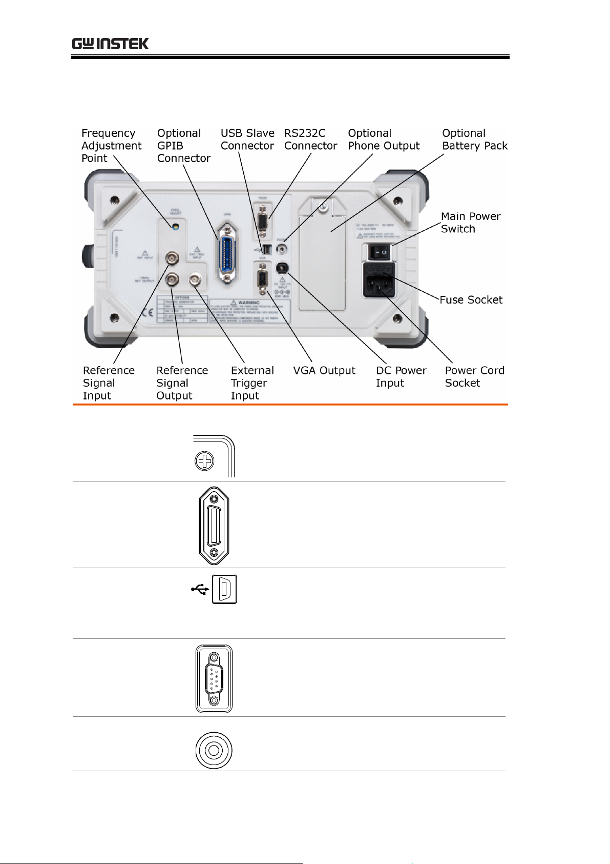
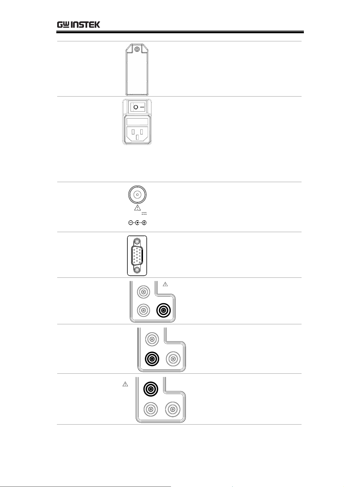
Rear Panel Overview
Frequency
Adjustment Point
GPIB Connector
(Optional)
USB Connector
RS232C
Connector
Phone Output
(Optional)
FREQ.
ADJUST
PHONE
Adjusts the internal reference signal
frequency; for service operation only.
Optional 24 pin female GPIB connector for
remote control (page157). For interface
setting details
, see page127.
Type B mini connector for PC software
connection (page150) and remote control
e157). For interface setting details, see
(pag
e126.
pag
9 pin female connector for PC software
connection (page150) and remote control
(pag
e157). For interface setting details, see
e126.
pag
3.5mm phone jack for audio output.
Available when the optional Demodulator is
installed. For details, see page144.
16
Page 17
GETTING STARTED
Battery Pack
(Optional)
Main Power
Switch,
Fuse Socket,
Power Cord
Socket
DC Power Input
DC 12V
INPUT
Stores the optional battery packs for
portable usage. For details, see page148.
The main power switch turns on/off the
GSP-830 main power. For the power up
sequence, see page20.
he fuse socket stores the main fuse, T1.6A
T
250V, time-delay, 5x20mm glass.
The power cord socket accepts the AC
power cord, 100 to 240V, 50/60Hz.
For power and fuse related safety
instructions, see page6.
DC power input, 12V, 40W max rating.
Accepts a standard 2.1mm DC plug or the
optional GTL-401 DC power cord. For
details, see page149.
VGA Output
External Trigger
Input
Reference Output
Reference Input
40W MAX.
10MHz
REF OUTPUT
REF INPUT
15pin, female VGA connector which
outputs 640 x 480 resolution display image
to an external monitor. For details, see
page111.
EXT. TRIG.
INPUT
Accepts a trigger signal from an
external device. For details, see
page103.
Outputs +5V TTL, 10MHz
reference signal used for
synchronizing the GSP-830 with
an external device. For details, see
page133.
Accepts a TTL signal from an
external device, used for
synchronization with the
GSP-830. For details, see
page134.
17
Page 18
GSP-830 User Manual
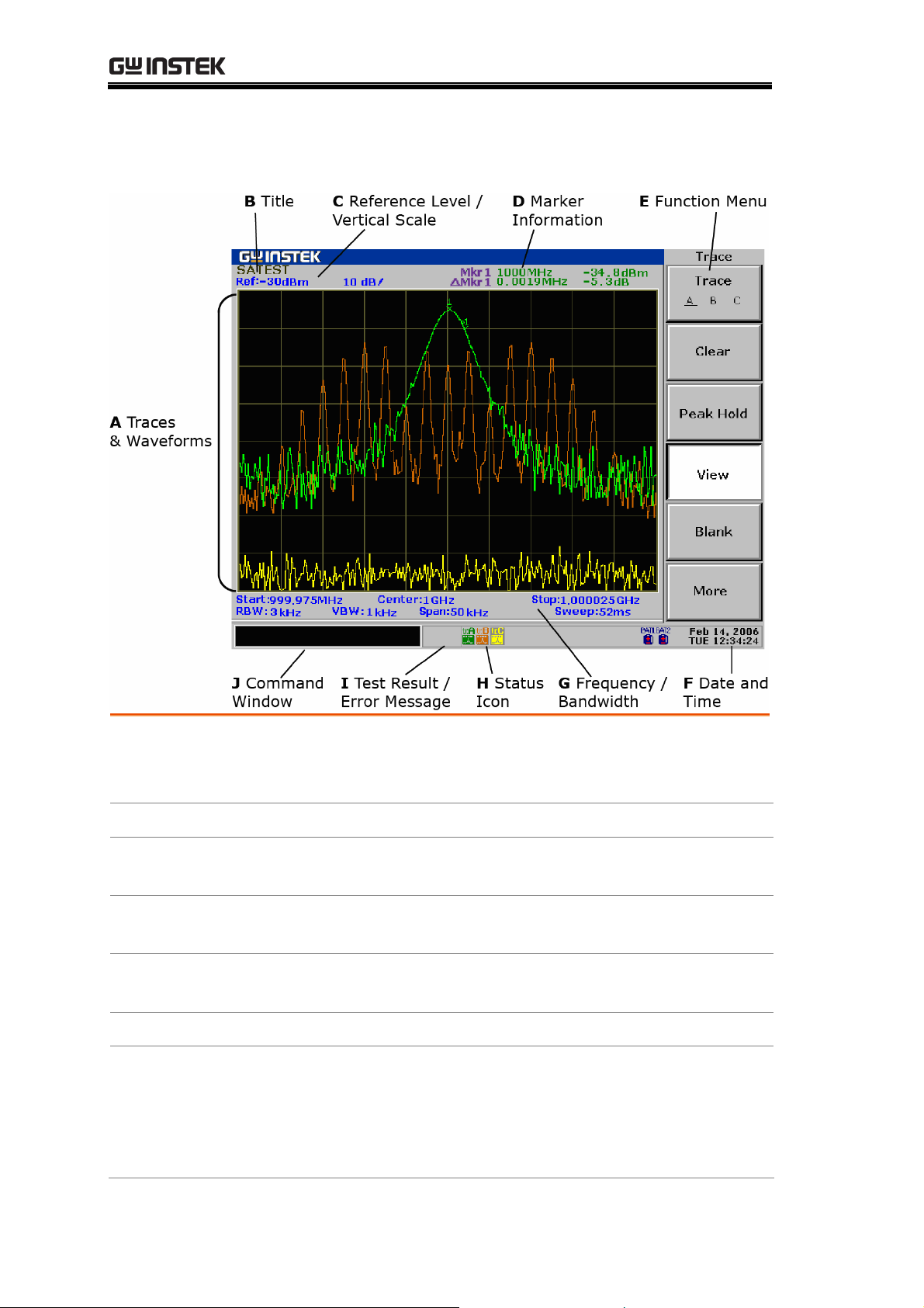
Display Overview
A Traces &
Waveforms
Input signals and traces that appear within the main
display area. Input signal & TraceA: Green, TraceB: Red,
TraceC: Yellow. For trace details, see page73.
B Title
C Reference
Level/Scale
D Marker
Information
E Function Menu
The title of the current display. For details, see page109.
The reference amplitude level and vertical scale. For
amplitude details, see page48.
The frequency and amplitude for the active marker /
delta marker. For marker details, see page62.
The menu associated with F1 to F6 function keys on the
right side of the display.
F Date and Time
G Frequency/
Bandwidth
Current date and time. For setup details, see page132.
Upper line: shows the start/stop frequency (page44) and
center frequency (page42).
Lo
RBW (resolution bandwidth - pag
(pag
wer line: shows the VBW (video bandwidth - page98),
e96), frequency span
e42), and sweep time (page101).
18
Page 19
GETTING STARTED
H Status Icon
The icons showing various system conditions. See the
below Status Icon overview for details.
I Test Result/
Error Message
J Command
Window
The result of the pass/fail test using limit lines (page94)
or the system error messages (page128).
Shows the current status of the selected menu or the
entered parameters such as frequency and amplitude.
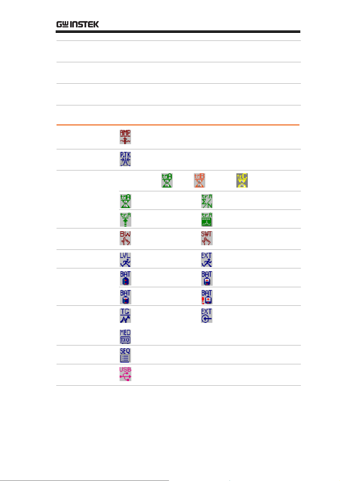
Status Icon overview
Amplitude
(page48)
Peak Search
(page68)
Trace (page73)
External gain on, amplitude correction on, Input
impedance 75Ω, Input impedance calibration on
Peak track on
TraceA:green , B:red , C:yellow
Clear mode
Average on
BW (page95)
Trigger (page103)
Battery level
(page148)
Options
Sequence(page136)
USB
Peak hold mode
View mode, trace math
RBW, VBW manual
mode
Video trigger mode
Sweep time manual mode
External trigger signal on
Fully charged
50% to 25%
75% to 50%
Less than 25%
TG normalization
activated (page142)
External reference signal
used (page133)
±1ppm stability module installed (page133)
Sequence currently running
USB flash drive is detected (page114), or USB
remote control connection is detected (pag
e158)
19
Page 20
GSP-830 User Manual
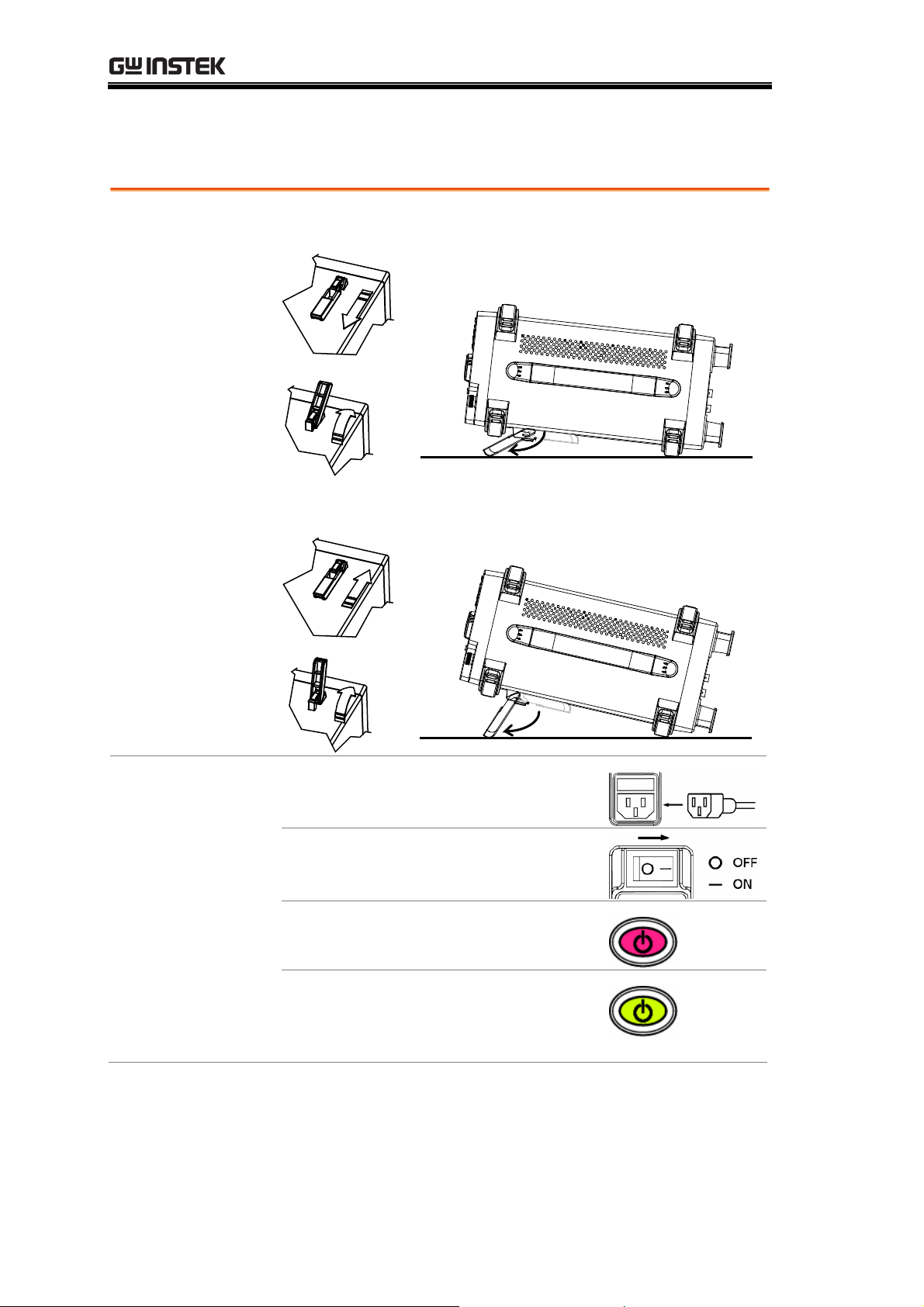
Tilt Stand & Power Up
Tilt stand
Low angle
High angle
Power Up
rear panel socket.
2. Turn on the main power switch.
3. The ON/STBY key on the front
panel turns red.
4. Press the ON/STBY key. Its
color turns green and the display
becomes active.
1. Connect the power cord to the
20
Page 21
GETTING STARTED
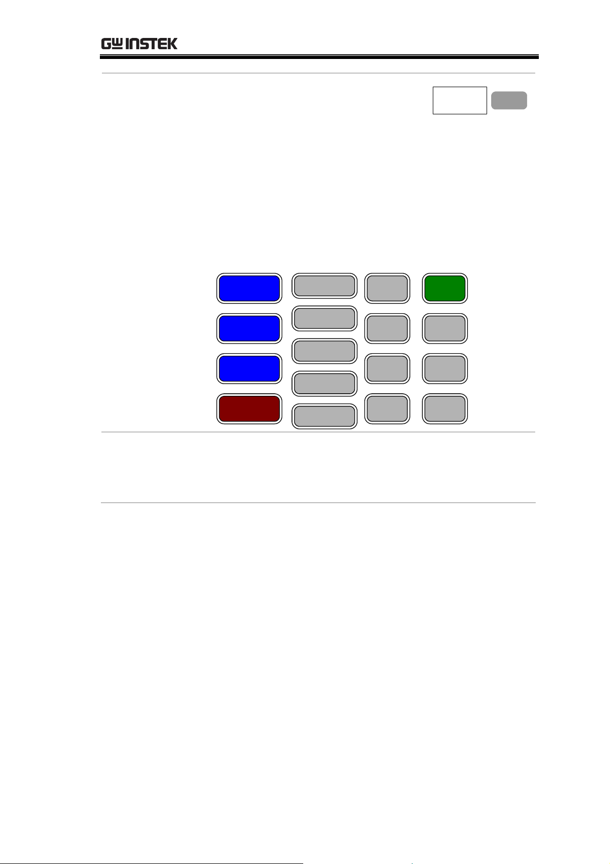
Last Stored Settings
At the initial state, only the F3 menu
“Last stored state” becomes available.
Last
stored
state
For details of storing the panel
settings, see page125.
To recall the last stored panel settings:
Press F3. One of the panel settings from S1 – S10,
which was stored the last time, will be recalled.
To use the GSP-830 without recalling the last stored
panel settings:
Press any other function keys (see below).
List of function keys
Frequency
Span
Amplitude
Marker
Peak Search
Trace
Meas
BW
Trigger
Display
Preset
System
Option
F 3
Note
Autoset
Limit Line
File Seq
Ignore the error message that might appear at the
bottom of the display when powering up the GSP-830.
The message indicates that internal configurations are
ongoing. For error message details, see page22.
21
Page 22
GSP-830 User Manual
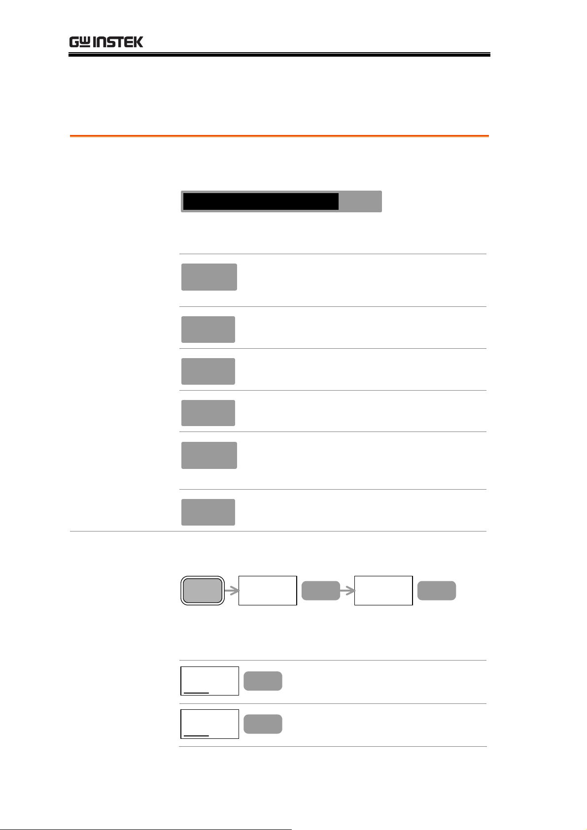
Error Check
This section assumes that the GSP-830 is already powered up (page20).
1. Check system
error
Check for error messages at the bottom of the display,
next to the command window.
Center : 1.5GHz
EXT
Unlock
(EXT Unlock)
Contact the service center if any of the following
messages remains in the display.
Amp
Uncal
EXT
Unlock
LO1
Unlock
LO3
Unlock
• Inappropriate RBW or VBW is selected.
• Frequency is less than 15MHz and
amplitude is less than 30dBm.
External reference input is not working
properly.
Local oscillator 1 is not working properly.
Local oscillator 3 is not working properly.
2. Check self test
result
Med
Unlock
±1ppm stability signal is not working
properly. Appears only when the optional
±1ppm stability module is installed.
Ref
Unlock
Internal reference signal is not working
properly.
View the GSP-830’s self-diagnosis test result. Press the
System key→F6 (More) →F2 (Self Test).
System
More...
F 6
Self Test...
F 2
The test automatically runs at each power-up. The
underline shows the result, pass or fail. Contact the
service center if any of the items fails.
GPIB
Pass
Flash
Pass
Fail
Fail
F 1
F 2
GPIB module connectivity
(available only when installed)
Internal Flash memory for storing
the system code/data
22
Page 23
GETTING STARTED
SDRAM
Pass
Fail
RTC
Pass
Fail
F 3
F 4
Internal SDRAM for running the
system code
Internal real time clock for
configuring the date and time
Functionality Check
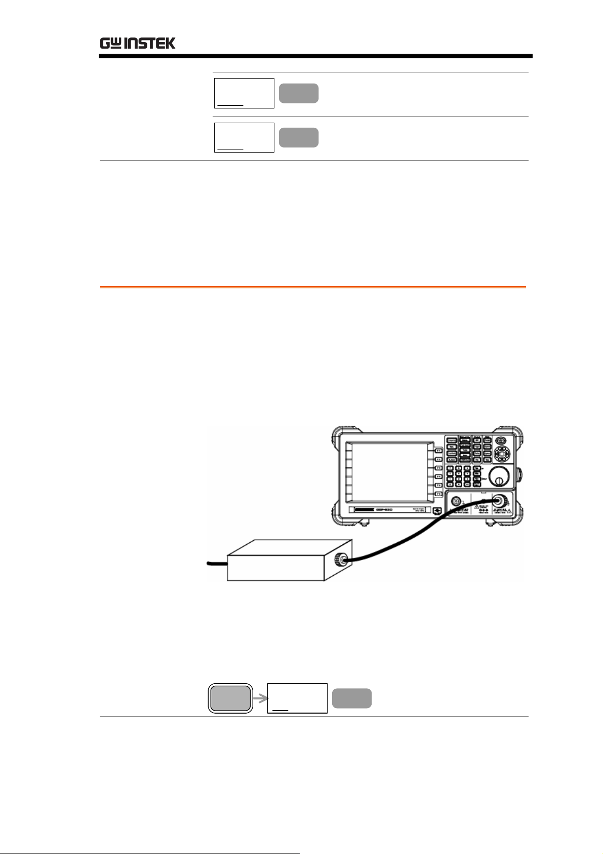
1. Feed a signal Input a signal to check if the GSP-830 correctly shows
• This section assumes that the GSP-830 is already
powered up (page20).
• Before operating the GSP-830 in a new environment,
run these steps to make sure it is functionally stable.
the waveform on the display. There are two ways to feed
an input signal.
Feeding the DUT signal
If the DUT is already available, connect the output signal
to the RF input terminal. The signal amplitude must be
less than +30dBm.
Feeding the internal auxiliary signal
You can also use the internal auxiliary signal,
100MHz/30dBm. No cable connection is required in
this case. Activate the signal by pressing the System key→
F4 (Aux Sig On).
System
Aux Sig
On
Off
F 4
23
Page 24
GSP-830 User Manual
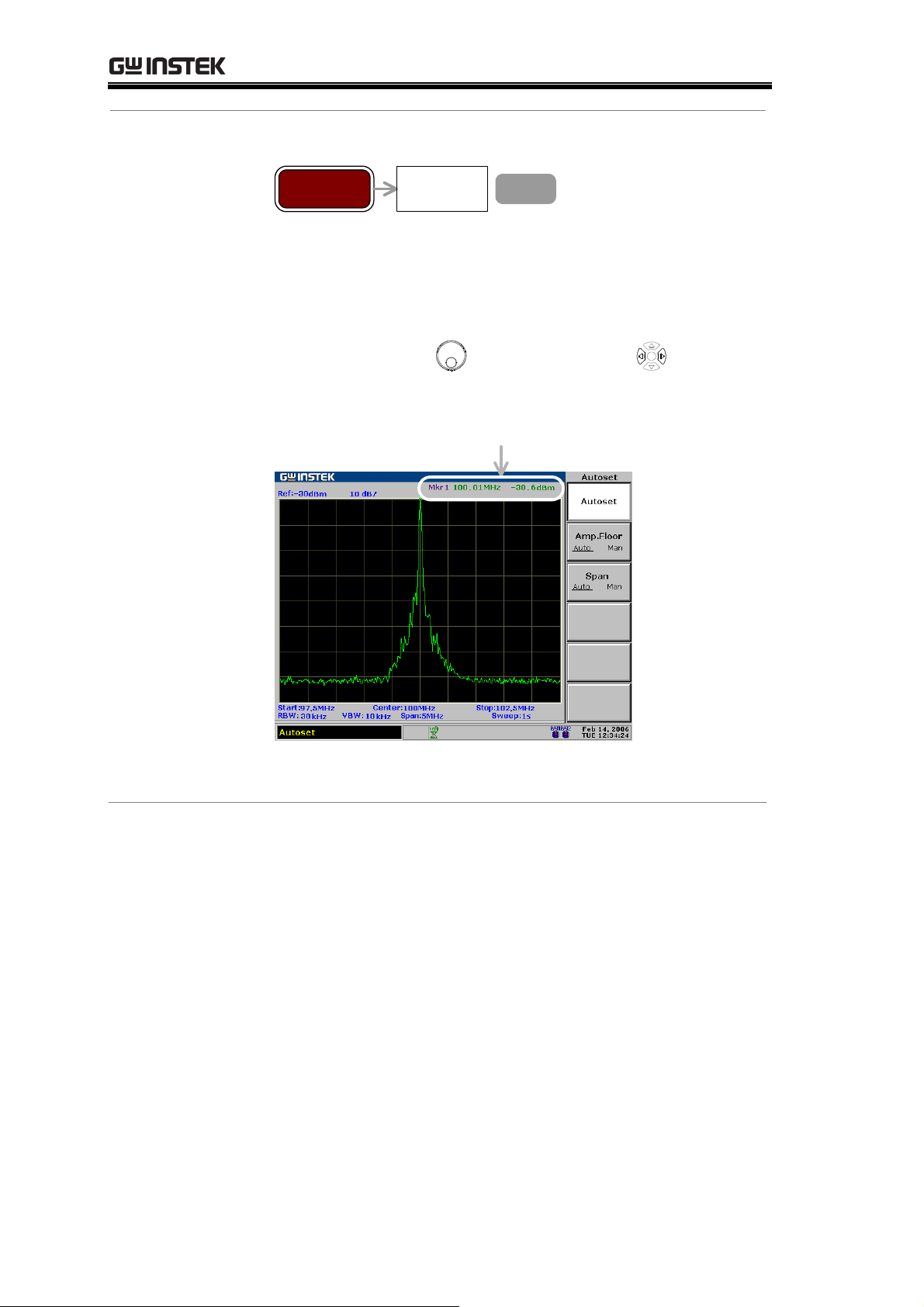
2. View the
signal
Press the Autoset key→F1 (Autoset).
Autoset Autoset
F 1
The GSP-830 automatically configures the horizontal and
vertical scales and shows the signal on the display.
Check the peak frequency and amplitude that appear on
the top right corner of the display. To move the marker,
use the Scroll knob
Internal auxiliary signal, -30dBm @100MHz
Peak frequency/amplitude
or Left/Right keys .
If the displayed value does not match the actual signal,
contact the service center.
24
Page 25

QUICK REFERENCE
QUICK REFERENCE
Shortcuts
Power-on screen
Frequency and Span ...............................................26
Amplitude...............................................................26
Autoset...................................................................26
Marker....................................................................26
Peak Search ............................................................27
Trace.......................................................................27
Power Measuremen
Limit Line ...............................................................28
Bandwidth ..............................................................28
Trigger ....................................................................28
Display ...................................................................29
File .........................................................................29
System....................................................................29
.....................................................26
t...............................................27
Menu T
Preset
ree
Option
Sequence................................................................30
Power-on screen
Frequency, Span, Autoset, Amplitude(1 of 2) .........31
Amplitude (2 of 2), Marker
Peak Search, T
Measurement, Lim
BW, Trigger, Display
File (1 of 2) ............................................................36
System....................................................................38
Option, Sequence
Preset Contents
....................................................................30
.....................................................31
.....................................32
race..................................................33
it Line .......................................34
................................................35
...................................................39
......................................................40
25
Page 26

GSP-830 User Manual
Operation Shortcuts
Here is the list of available operations and their shortcuts.
Power-on screen
Recall the last stored settings
Frequency and Span
Set Center Frequency and Span
F3
Frequency→F1→Span→F1
Set Start and Stop Frequency
Set Frequency Step
Activate Full Span (3.0GHz)
Activate Zero Span (Time Domain)
Recall Last Span
Amplitude
Set Reference Level
Select Vertical Scale
Select Unit (dBm/dBmV/dBuV)
Set External Gain
Activate Amplitude Correction
Select Amplitude Correction Set
Delete Amplitude Correction Item
Delete Amplitude Correction Set
Undo Correction Item/Set Deletion
Frequency→F2(Start), F3(Stop)
Frequency→F4
Span→F2
Span→F3
Span→F4
Amplitude→F1
Amplitude→F2
Amplitude→F3→F1 to F3
Amplitude→F4
Amplitude→F5→F2
Amplitude→F5→F1→F1
Amplitude→F5→F1→F2
Amplitude→F5→F1→F3→F2
Amplitude→F5→F1→F4
Save Amplitude Correction Set
Select Input Impedance (50Ω/75Ω)
Set Input Impedance Offset
Autoset
Run Autoset
Set Amplitude Floor
Set Frequency View Span
Marker
Activate Normal Marker
26
Amplitude→F5→F1→F5
Amplitude→F6→F1
Amplitude→F6→F2
Autoset→F1
Autoset→F2
Autoset→F3
Marker→F1→F2
Page 27

QUICK REFERENCE
Activate Delta Marker
Activate All Normal Markers
Move Marker to Peak
Move Marker and Peak to Center
Track Marker on Peak
Move Marker to Various Locations
Show Marker Table
Put Marker on Trace
Peak Search
Search Peak Signal
Search Next Peak
Search Next Peak to Right
Search Next Peak to Left
Search Peak and Move to Center
Track Marker on Peak
Marker→F1→F2→F3
Marker→F6→F3
Marker→F4 or Peak Search
Marker→F4→F5 or Peak Search→F5
Peak Search→F6→F4
Marker→F6→F4→F1 to F5
Marker→F6→F2
Marker→F6→F1
Peak Search or Marker→F4
Peak Search→F2
Peak Search→F3
Peak Search→F4
Peak Search→F5 or Marker→F4→F5
Peak Search→F6→F4
Search Minimum Amplitude
Show Peak Table
Sort Peaks in Peak Table
Set Peak Threshold
Trace
Activate Trace
Clear Trace (Update in Real-Time)
View Peak Hold Trace
Freeze Trace
Hide Trace
View Averaged Trace
Run Trace Math
Select Signal Detection Mode
Power Measurement
Activate ACPR
Peak Search→F6→F5
Peak Search→F6→F1
Peak Search→F6→F2
Peak Search→F6→F3
Trace→F1
Trace→F2
Trace→F3
Trace→F4
Trace→F5
Trace→F6→F1 or BW→F4
Trace→F6→F2→F1 to F5
Trace→F6→F3→F1 to F5
Meas→F2
Set ACPR Channel Bandwidth
Set ACPR Channel Space
Set ACPR Adjacent Channel Offset
Meas→F1→F1
Meas→F1→F2
Meas→F1→F4→F2 and F4
27
Page 28

GSP-830 User Manual
Set ACPR Adjacent Channel BW
Move ACPR Channel Up
Move ACPR Channel Down
Activate OCBW
Set OCBW Channel Bandwidth
Set OCBW Channel Space
Set OCBW %
Move OCBW Channel Up
Move OCBW Channel Down
Activate N dB
Set N dB Value
Activate Phase Jitter
Set Phase Jitter Offset
Limit Line
Activate Limit Line
Meas→F1→F4→F1 and F3
Meas→F4
Meas→F5
Meas→F3
Meas→F1→F1
Meas→F1→F2
Meas→F1→F3
Meas→F4
Meas→F5
Meas→F6→F1
Meas→F6→F2
Meas→F6→F3
Meas→F6→F4→F1(Start), F2(Stop)
Limit Line→F1 (High), F2 (Low)
Select Limit Line for Edit
Activate Limit Line Edit Table
Delete Limit Line Table Item
Delete All Table Item
Undo Last Deletion
Run Pass/Fail Test
Select Pass/Fail Condition
Bandwidth
Select RBW
Select VBW
Set Sweep Time
Set Trace Average Number
Reset RBW/VBW/Sweep to Auto
Trigger
Select Free Run (Default)
Limit Line→F3→F1
Limit Line→F3→F2
Limit Line→F3→F3
Limit Line→F3→F4→F2
Limit Line→F3→F5
Limit Line→F4
Limit Line→F5
BW→F1
BW→F2
BW→F3
BW→F4 or Trace→F6→F1
BW→F5
Trig ger→F1
Select Video/External Trigger
Select Trigger Mode
Set Trigger Delay
28
Trig ger→F2
Trig ger→F3
Trig ger→F4
Page 29

QUICK REFERENCE
Set Trigger Frequency
Run Trigger (in Single/Continuous)
Display
Change Dimmer Level
Show Display Line
Clear Title
Enter Title
Show Title
Activate Split Window
Alternate Upper/Lower Sweep
Switch Split Display to Full Screen
File
Select Copy Source File
Select Copy Destination File
Trig ger→F5
Trig ger→F6
Display→F1
Display→F2
Display→F3→F1
Display→F3→F2 to F4
Display→F3→F5
Display→F4→F1 (Upper), F2 (Lower)
Display→F4→F3
Display→F4→F4
File→F1→F1→F1 to F5
F2→F1 to F5 (After Selecting Source)
Edit Copied File Name
Copy Selected File
Select File for Deletion
Delete Selected File
Rename File
Confirm New File Name
Save Display Image to USB Drive
Rename File in USB Drive
Select System Code for Update
Select Language for Update
Update System File from USB Drive
Preset
Recall Factory Installed Settings
System
Save Setup
F3 (After Selecting Destination)
F4 (After Selecting Source/Destination)
File→F2→F1→F1 to F5
F2 (After Selecting File)
File→F3→F1
F2 (After Renaming File)
File→F4→F1→F2
File→F4→F1→F1
File→F5→F1→F1
File→F5→F1→F2
F2 (After Selecting File)
Preset
System→F1→F1 or F2→F3
Recall Setup
Select GPIB Address
Show RS-232C Configuration
Activate Auxiliary Signal
System→F1→F1 or F2→F4
System→F2
System→F3→F1 to F4
System→F4
29
Page 30

GSP-830 User Manual
Set Date
Set Time
Activate Clock Display
View Self Test Result
View System Configuration
Select Language
Option
Activate Tracking Generator
Set Tracking Generator Amplitude
Normalize Tracking Generator
Activate Normalized TG
Set Ref Level for TG Normalization
Activate FM Demodulator
Activate AM Demodulator
Activate Phone Output
System→F6→F1→F1→F1 to F4
System→F6→F1→F2→F1 to F3
System→F6→F1→F3
System→F6→F2
System→F6→F4
System→F6→F5→F1
Option→F1→F1
Option→F1→F2
Option→F1→F3→F2
Option→F1→F4
Option→F1→F5
Option→F2→F1
Option→F2→F2
Option→F2→F3
Set Phone Output Volume
Set Squelch Level
View Battery Level
Set Ext. Reference Signal Frequency
Sequence
Select Sequence Set
Start Sequence Edit
Insert 100ms Delay
Insert Pause in Sequence
Insert Another Sequence Set
Stop Sequence Edit
Insert Item to Sequence Set
Save Sequence Set
Delete Sequence Item
Delete Sequence Set
Option→F2→F4
Option→F2→F5
Option→F3
Option→F4
Sequence→F1, F2
Sequence→F3→F1
Sequence→F3→F2
Sequence→F3→F3
Sequence→F3→F4→F1 to F2
Sequence→F3→F5
Sequence→F3→F6→F1
Sequence→F3→F6→F2
Sequence→F3→F6→F3
Sequence→F3→F6→F4→F2
Undo Sequence Item/Set Delete
Select Sequence Run Mode
Run Sequence
Delete All Sequence Set
30
Sequence→F3→F6→F5
Sequence→F4→F1
Sequence→F4→F2
Sequence→F5→F2
Page 31

QUICK REFERENCE
Menu Tree
Power-on screen
Last
stored
state
Frequency, Span, Autoset, Amplitude(1 of 2)
F 3
Frequency
Center
1.5 GHz
Start
0 kHz
Stop
3 GHz
Step
1 MHz
Amplitude
Ref.Level
0 dBm
Scale dB/Div
10 5 2 1
F 1
F 2
F 3
F 4
F 1
F 2
Span
Span
3 GHz
Full Span
Zero Span
Last Span
dBm
dBmV
F 1
F 2
F 3
F 4
F 1
F 2
Autoset
Autoset
Amp.Floor
Auto
Man
Span
Man
Auto
F 1
F 2
F 3
Units...
Ext.Gain
0dB
Corrections..
More
F 3
F 4
F 5
F 6
dBuV
Return
F 3
F 6
31
Page 32

GSP-830 User Manual
Amplitude (2 of 2), Marker
32
Page 33

QUICK REFERENCE
Peak Search, Trace
Peak Sear ch
Pk Search
Next Peak
Next Pk
Right
Next Pk
Left
Mkr Center
More
Trace
Trace
A
B C
Clear
F 1
F 2
F 3
F 4
F 5
F 6
F 1
F 2
Peak Table
On Off
Peak Sort
Amp
Freq
Pk Threshold
On Off
Track
On Off
Min Search
Return
AVG
On Off
20
Trace Math..
F 1
F 2
F 3
F 4
F 5
F 6
F 1
F 2
A B
A+B A
F 1
F 2
Peak Hold
View
Blank
More
F 3
F 4
F 5
F 6
Detection..
Return
F 3
F 6
A-B A
A+const A
A-const A
Return
Normal
Sample
Peak+
AVG
QPeak
F 3
F 4
F 5
F 6
F 1
F 2
F 3
F 4
F 5
Return
F 6
33
Page 34

GSP-830 User Manual
Measurement, Limit Line
Meas
Channel
Setup...
ACPR
On Off
OCBW
On Off
CH Up
CH Down
More
F 1
F 2
F 3
F 4
F 5
F 6
CH BW
CH SPC
OCBW %
ADJ CH
Offset...
Return
N dB BW
On Off
N dB
Phase Jitter
On Off
F 1
F 2
F 3
F 4
F 6
F 1
F 2
F 3
Adj CH BW1
Adj CH Offs1
Adj CH BW2
Adj CH Offs2
Return
Start
Offset
Stop
Offset
F 1
F 2
F 3
F 4
F 6
F 1
F 2
Limit Line
H Limit
On Off
L Limit
On Off
Edit...
Pass/Fail
On Off
Pass/Fail
___
F 1
F 2
F 3
F 4
F 5
Phase Jitter
Setup..
Return
Limit
Low High
Edit Table
Off
On
Delete
Delete All..
Undelete
F 4
F 6
F 1
F 2
F 3
F 4
F 5
Return
No
Yes
F 6
F 1
F 2
34
Return
F 6
Page 35

QUICK REFERENCE
BW, Trigger, Display
BW
RBW
Auto
Man
VBW
Auto
Man
Swp Tm
Auto
Man
AVG
On Off
20
All Auto
Display
LCD Dimmer
F 1
F 2
F 3
F 4
F 5
F 1
Trigger
Free Run
Trigger
Condition
Video Ext.
Trigger Mode
Nor. Sgl. Cont.
Trigger Delay
50ms
Trigger Freq
1.5GHz
Run Now
Clear Title
F 1
F 2
F 3
F 4
F 5
F 6
F 1
Upper
F 1
Display Line
On Off
Title...
Split
Window...
F 2
F 3
F 4
(Capital
Letter)
(Small
Letter)
(Symbol)
Show Title
Return
F 2
F 3
F 4
F 5
F 6
Lower
Alternate
Sweep
Full Screen
Return
F 2
F 3
F 4
F 6
35
Page 36

GSP-830 User Manual
File (1 of 2)
File
Copy...
Delete...
Rename...
F 1
F 2
F 3
Source..
Destination..
Edit File Name
On Off
Copy Now
Return
Type...
Delete Now
F 1
F 2
F 3
F 4
F 6
F 1
F 2
Trace
Int.
Ext.
Limit
Int.
Ext.
Correction
Int.
Ext.
Seq.
Ext.
Int.
Setup
Ext.
Int.
Return
Trace
Ext.
Int.
Limit
Int.
Ext.
Correction
Int.
Ext.
F 1
F 2
F 3
F 4
F 5
F 6
F 1
F 2
F 3
Print Screen..
Update
From
Flash Drive
F 4
F 5
Return
F 6
Seq.
Int.
Ext.
Setup
Int.
Ext.
Return
F 4
F 5
F 6
36
Page 37

QUICK REFERENCE
File (2 of 2)
File
Copy...
Delete...
Rename...
F 1
F 2
F 3
Edit File Name
On Off
Confirm
Return
To Ext.
Memory...
F 1
F 2
F 6
F 1
Edit File Name
On Off
Print Now
F 1
F 2
Print Screen..
Update
From
Flash Drive
Preset
Preset
F 4
F 5
(No menu item)
Return
Type...
Update Now
Return
F 6
F 1 F 1
F 2
F 6
Return
System Code
Multi
Language
Return
F 6
F 2
F 6
37
Page 38

System
System
GSP-830 User Manual
Save/Recall
Setup..
GPIB Add
2
Serial Port..
Aux Sig
On Off
Service...
*
More...
System
Clock...
Self Test...
RF Diagno...
*
F 1
F 2
F 3
F 4
F 5
F 6
F 1
F 2
F 3
Baud
57600
Parity
None
Stop
Data
Return
Date...
Time...
Clock
On
Off
F 1
F 2
1
8
F 3
F 4
F 6
F 1
F 2
F 3
Setup
1
2 3 4 5
Setup
6 7 8 9 10
Save Now
Recall Now
Return
Year
Month
Day
F 1
F 2
F 3
F 4
F 6
F 1
F 2
F 3
System Config
On Off
Language
Return
(English)
Return
F 4
F 5
F 6
F 1
F 6
Return
GPIB
Pass
Fail
Flash
Pass
Fail
SDRAM
Pass
Fail
RTC
Fail
Pass
Return
F 6
F 1
F 2
F 3
F 4
F 6
Day of
Week
Return
Hour
Minute
Second
Return
F 4
F 6
F 1
F 2
F 3
F 6
* Submenu only for service personnel
38
Page 39

QUICK REFERENCE
Option, Sequence
Option
TG...
Demod...
Battery
Ext Ref Freq
10MHz
Seq
Select Seq
1
2 3 4 5
Select Seq
6 7 8 9 10
Edit...
F 1
F 2
F 3
F 4
F 1
F 2
F 3
FM
On Off
AM
On Off
SPK
On Off
Volume
Squelch
Return
Start Edit
Delay ms
100 X
Wait to go
F 1
F 2
F 3
F 4
F 5
F 6
F 1
F 2
F 3
TG
Off
On
TG Level
Execute
Norm..
Norm Corr
On Off
Ref Value
Return
Seq.Index
1
2 3 4 5
Seq.Index
6 7 8 9 10
F 1
F 2
F 3
F 4
F 5
F 6
F 1
F 2
No
Yes
Return
F 1
F 2
F 6
Run...
Delete
Seq All...
No
Yes
Return
F 4
F 5
F 1
F 2
F 6
Do Seq...
Stop Edit
More
Run Mode
Rept. Sngl.
Run Now
Return
F 4
F 5
F 6
F 1
F 2
F 6
Return
Insert
Save
Delete
Delete All..
Undelete
Return
F 6
F 1
F 2
F 3
F 4
F 5
F 6
No
Yes
Return
F 1
F 2
F 6
39
Page 40

GSP-830 User Manual
Preset Contents
These are the settings that appear when pressing the Preset key
Frequency
Span
Amplitude
Center: 1.5GHz
Start: 0Hz
3GHz
Ref.level: 0dBm
Unit: dBm
Stop: 3GHz
Step: 1MHz
External Gain: 0dB
Input Z: 50
Scale: 10dB/
Autoset
Marker
Peak Search
Tr ace
Meas
Amplitude Floor: Auto Span: Auto
Marker: Off
Marker Table: Off
Peak Table: Off
Peak Threshold: Off
Trace: A
Average: Off, 20
ACPR: Off
CH SPC: 0
CH BW: 600MHz
OCBW %: 0
Marker Trace: Auto
All Marker: Off
Peak Sort: Freq
Peak Track: Off
Mode: Clear
Detection: Normal
OCBW: Off
Adj CH Offs: 0MHz
Adj CH BWs: 0MHz
Phase Jitter: Off
N dB: Off
Preset
.
Limit Line
BW
Trigger
Display
File
System
Option
Sequence
H & L Limit: Off Pass/ Fail: Off
RBW: Auto
SwpTime: Auto
Trigger Delay: 50ms
VBW: Auto
Average: Off, 20
Trigger Freq: 1.5GHz
Trigger Mode: Normal
LCD Dimmer: 5
Split Window: Off
Copy Type: Int. Trace
Display Line: Off
Display Title: Off
Delete Type: Int. Trace
Rename Type: Ext. Trace
GPIB Add: 2
Aux Sig: Off
External Ref Freq: 10MHz
TG Norm Corr: Off
Demod AM: Off
System Config: Off
Clock: On
TG Output: Off
TG Ref Value: 0dBm
Demod FM: Off
Sequence: 1 Run Mode: Single
40
Page 41

FREQUENCY/SPAN
FREQUENCY/SPAN
The Frequency key, together with Span key, sets the
frequency scale. Two methods are available.
Center-and-Span method defines the center point and
surrounding frequency range. Start-and-Stop method
defines the beginning and end of the frequency range.
Special span settings are available at full and zero spans.
The last span setting may also be recalled.
Frequency
Center and Span
Start and Stop
Span
Set frequency adj
Set center frequency...............................................42
Set frequency span .................................................43
Set frequency adj
Set start frequency .................................................44
Set stop frequency..................................................45
Display full frequen
ustment step ...............................42
ustment Step...............................44
cy span (3GHz) .......................46
Display zero span (time domain) ...........................46
Recall the Last Span Setting...................................47
41
Page 42

GSP-830 User Manual
View Signal (Center and Span)
Center-and-Span method defines the center frequency
and the left/right bandwidth (span) to locate the signal.
Set frequency adjustment step
Background
Frequency adjustment step defines
the Arrow keys resolution for center,
start, and stop frequency.
Panel operation
1. Press the Frequency key.
2. Press F4 (Step).
3. Enter the value using the
Numerical and Unit keys, Arrow
keys, and Scroll knob.
Range
0kHz to 3GHz
* Arrow keys and Scroll knob resolution: 1/10 of Span
Set center frequency
Panel operation
1. Press the Frequency key.
2. Press F1 (Center).
3. Enter the value using the
Numerical and Unit keys, Arrow
keys, or Scroll knob.
Frequency
Step
1 MHz
GHz /
dB
Sec
MHz /
mSec
kHz /
Enter
μ
Sec
BK SP
Frequency
Center
1.5 GHz
GHz /
dB
Sec
MHz /
mSec
kHz /
Enter
μ
Sec
BK SP
F 4
F 1
Range
Note
42
0kHz to 3GHz
Arrow keys and Scroll knob resolution: step value
Center frequency and span settings automatically change
according to start and stop frequency settings, and vice
versa.
Page 43

FREQUENCY/SPAN
Display
Set frequency span
Panel operation
1. Press the Span key.
Center
Frequency
reading
Span
Range
Display
2. Press F1 (Span).
3. Enter the value using the
Numerical and Unit keys, Arrow
Span
3 GHz
F 1
GHz /
dB
Sec
MHz /
mSec
kHz /
Enter
μ
Sec
BK SP
keys, and Scroll knob.
2kHz to 3GHz
* Arrow keys & Scroll knob resolution: 1-2-5 sequence
(0 [zero span], 2kHz, 5kHz, 10kHz, 20kHz, 50kHz,
.....1GHz, 2GHz, 3GHz)
Span
Span
reading
Note
• Center frequency and span settings automatically
change according to start and stop frequency settings,
and vice versa.
• If the span becomes smaller than the CHBW (channel
bandwidth) in the ACPR or OCBW measurement
(page82), the warning “Span is less than CHBW!”
appears in the comma
nd window.
43
Page 44

GSP-830 User Manual
View Signal (Start and Stop)
Start-and-Stop method defines the beginning (start) and
the end (stop) of the frequency range.
Set frequency adjustment Step
Background
Frequency adjustment step defines
the Arrow keys resolution for
Center, Start, and Stop frequency.
Panel operation
Range
1. Press the Frequency key.
2. Press F4 (Step).
3. Enter the value using the
0.0kHz to 3.0GHz
* Arrow keys and Scroll knob resolution: 1/10 of span
Set start frequency
Panel operation
1. Press the Frequency key.
2. Press F2 (Start).
3. Enter the value using the
Numerical and Unit keys, Arrow
keys, and Scroll knob.
Numerical and Unit keys,
Arrow keys, and Scroll knob.
Frequency
Step
0 kHz
GHz /
dB
Sec
MHz /
mSec
kHz /
Enter
μ
Sec
BK SP
Frequency
Start
0 kHz
GHz /
dB
Sec
MHz /
mSec
kHz /
Enter
μ
Sec
BK SP
F 4
F 2
Range
Note
44
0kHz to 3GHz (start frequency stop frequency)
Arrow keys and Scroll knob resolution: step value
Center frequency and span settings automatically change
according to start and stop frequency settings, and vice
versa.
Page 45

FREQUENCY/SPAN
Display
Start
Frequency
Set stop frequency
Panel operation
1. Press the Frequency key.
Frequency
reading
Frequency
Range
Display
2. Press F3 (Stop).
3. Enter the value using the
Numerical and Unit Keys,
Stop
3 GHz
F 3
GHz /
dB
Sec
MHz /
mSec
kHz /
Enter
μ
Sec
BK SP
Arrow keys, and Scroll knob.
0.0kHz to 3.0GHz (start frequency stop frequency)
* Arrow keys and Scroll knob resolution: step value
Stop
Frequency
Frequency
reading
Note
Center frequency and span settings automatically change
according to start and stop frequency settings, and vice
versa.
45
Page 46

GSP-830 User Manual
Full/Zero Span
Full or zero span setting sets the span to extreme values:
3GHz (full) or 0kHz (zero). They provide faster ways to
view signals in certain situations, such as in time domain
(zero span) for viewing modulation or in full span for
viewing signals with unknown frequencies.
Display full frequency span (3GHz)
Panel operation
1. Press the Span key.
Span
Range
Display
2. Press F2 (Full Span).
Full Span
3GHz (fixed)
Full span also sets these parameters to fixed values.
• Center frequency: 1.5GHz
• Start frequency: 0.0kHz
• Stop frequency: 3.0GHz
Full Span
3.0GHz
reading
F 2
Display zero span (time domain)
Panel operation
Range
46
1. Press the Span key.
2. Press F3 (Zero Span).
Center frequency (fixed)
Span
Zero Span
F 3
Page 47

FREQUENCY/SPAN
Display
Zero span also sets these parameters to fixed values.
• Start frequency: same as the center frequency
• Stop frequency: same as the center frequency
The diagram shows an example of observing the
amplitude modulation of the input signal.
Amplitude
modulation
Start=
Center=
Stop
frequency
0kHz Span
Note
When using zero span for viewing amplitude modulation,
make sure that the RBW setting is large enough. For
RBW setting details, see page96.
Recall the Last Span Setting
Panel operation
Nesting level
1. Press the Span key.
2. Press F4 (Last Span).
3. The span setting goes back to
the previous one.
1 level
Span
Last Span
F 4
47
Page 48
GSP-830 User Manual
AMPLITUDE
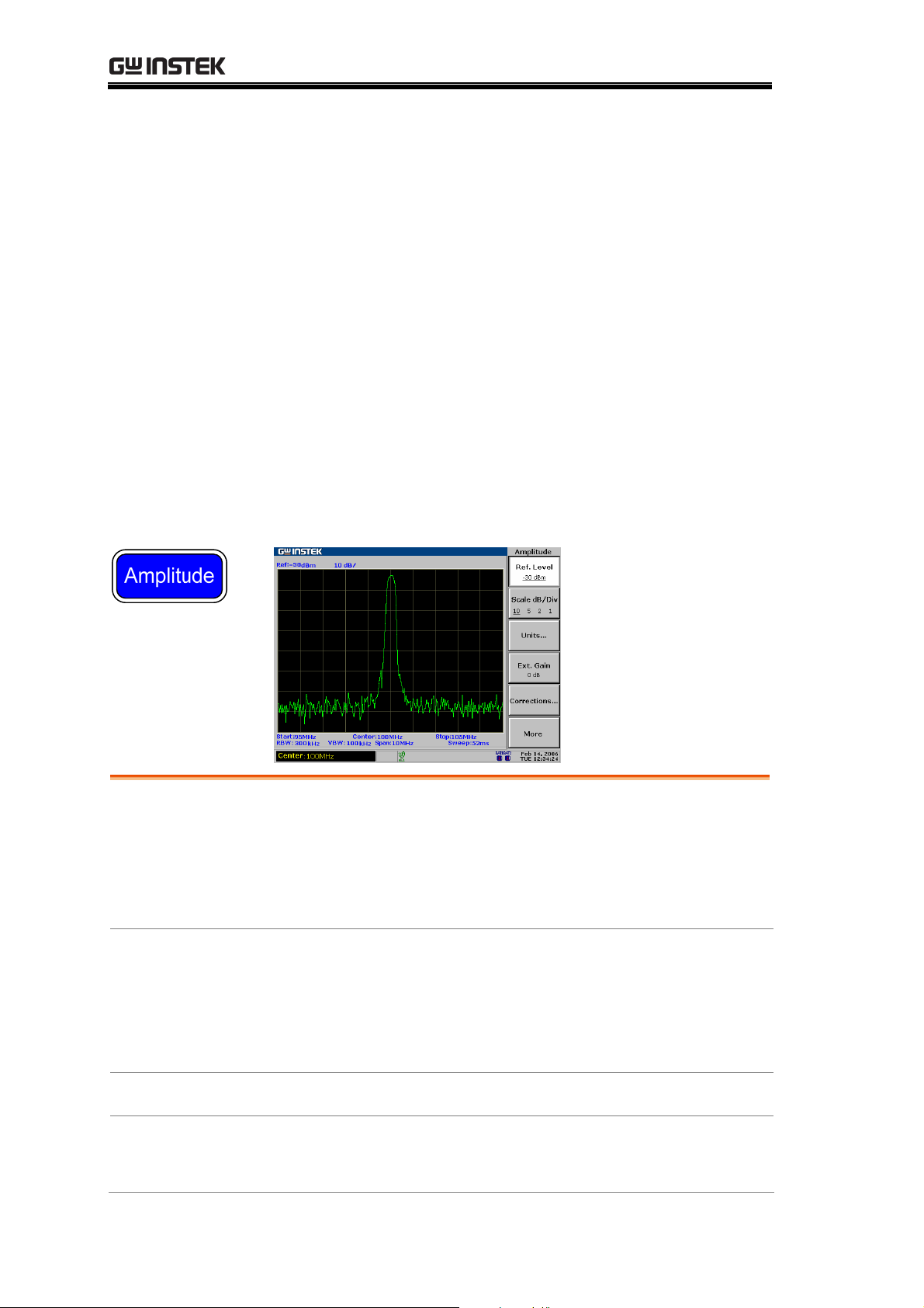
The Amplitude key sets the vertical attribute of the
display, including the upper limit (reference level), vertical
range (amplitude scale), vertical unit, and compensation
for external gain or loss (external offset). Amplitude
correction adjusts the frequency response distortion
caused by external networks. The optional pre-amplifier
GAP-801 and GAP-802 boosts the level of a weak input
signal before it enters the GSP-830. The input
impedance can also be adjusted according to the
application needs.
Vertical Scale
Setting
Amplitude
Correction
Set reference ampli
Select amplitude s
Select amplitude un
Set external offset
Correct amplitude step by
Delete entire correct
Recall existing corre
tude......................................... 49
cale........................................... 50
it ............................................ 50
level ......................................... 51
ion set data ........................... 55
ction set................................. 55
step.............................. 52
Pre-Amplifier
Input
Impedance
48
Save/copy/delete/rename corr
Use Pre-Amplifier (
Select input impedance (50Ω/75Ω)
Set impedance offset (75Ω only)
Optional)................................. 56
ection file............... 56
.......................... 57
...................... 57
Page 49

AMPLITUDE
Set Vertical Scale
Vertical display scale is defined by the reference
amplitude, amplitude range, measurement unit, and
external gain/loss.
Set reference amplitude
The reference level defines the amplitude at the top of the displayed range
(see below screen snapshot).
Panel operation
1. Press the Amplitude key.
Amplitude
2. Press F1 (Ref.Level).
3. Enter the value using the
Numerical and Unit keys, Arrow
keys, and Scroll knob.
*Arrow keys and Scroll knob resolution: vertical
scale
Range dBm
dBmV
dBuV
Display
See page50 for selecting amplitude units.
Reference Level Reading
110 to +20 dBm, 0.1dB resolution
63.01 to +66.99 dBmV, 0.01dB resolution
3.01 to +126.99 dBuV, 0.01dB resolution
Ref.Level
-30.0dBm
GHz /
dB
Sec
MHz /
mSec
kHz /
μ
Sec
BK SP
Reference
level
F 1
Enter
49
Page 50

GSP-830 User Manual
Select amplitude scale
Panel operation
1. Press the Amplitude key.
Amplitude
Range
Display
2. Press F2 (Scale dB/Div)
repeatedly to select the scale.
10, 5, 2, 1 dB/Div
Scale reading
Scale dB/Div
10 5 2 1
F 2
Select amplitude unit
Panel operation
Range dBm
dBmV
1. Press the Amplitude key.
2. Press F3 (Units).
3. Select and press the unit from
F1 (dBm), F2 (dBmV), and F3
(dBuV).
4. Press F6 (Return) to go back to
the previous menu.
110 to +20 dBm
63.01 to +26.99 dBmV
Amplitude
Units...
dBm
dBmV
dBuV
Return
F 3
F 1
F 2
F 3
F 6
dBuV
3.01 to +126.99 dBuV
50
Page 51

AMPLITUDE
Set external offset level
Background
External offset compensates the amplitude gain or loss
caused by an external network or device.
Panel operation
Range
Icon
Example
Before (offset: 0dB)
1. Press the Amplitude key.
2. Press F4 (Ext.Gain).
3. Enter the value using the
Numerical keys and dB or Enter
key.
20.0dB to +20.0dB, 0.1dB resolution
The amplitude icon appears at the bottom of
the display when the external offset changes.
Reference: -27dBm
Amplitude
Ext.Gain
0dB
GHz /
Sec
MHz /
mSec
kHz /
Sec
μ
BK SP
F 4
dB
Enter
After (offset: −3dB)
Offset:
0dB
Reference: -30dBm
Offset:
-3dB
Icon
51
Page 52

GSP-830 User Manual
Amplitude Correction
Overview
Background
Amplitude correction adjusts the GSP-830’s frequency
response by changing amplitudes for specific frequencies.
Range Correction set
Amplitude
5 sets, 30 correction points each
40 to +40dB per correction point,
0.1dB resolution
Frequency
Icon
The amplitude icon appears at the bottom of
the display when amplitude correction is on.
9kHz to 3GHz, 1kHz resolution
Correct amplitude step by step
Example
description
Correction level
2.2GHz
2.3GHz
In this example, the network between the GSP-830 and
DUT distorts the waveform and pushes the amplitude
down at around 2.4GHz. Amplitude correction can bring
the amplitude back to its original level.
In this example the amplitude around 2.4GHz is boosted
by +1 to +3dB as shown below.
+2.5dB
+1.3dB
2.4GHz
2.5GHz
2.6GHz
Waveform (before
correction)
The frequency response is distorted (non-flat) and the
level is attenuated by 2 to 3dB.
+2.8dB
+2.5dB
+1.2dB
52
Page 53

AMPLITUDE
1. Enter correction
edit mode
2. Select correction
set
1. Press the Amplitude key.
2. Press F5 (Corrections).
3. Press F1 (Edit). The display
shows the correction sets.
Press F1 (Select) repeatedly to
select the correction set. 5 sets, 30
points each, are selectable.
Amplitude
Corrections..
Edit...
Select
1
2 3 4 5
F 5
F 1
F 1
Example: correction set 3 selected
3a. Add correction
point
1. Make sure that the cursor is
pointing to the first empty
frequency point.
2. If necessary, move the cursor
using the Up/Down keys.
3. Enter the frequency using the
Numerical and Unit keys:
9kHz to 3GHz.
4. The cursor automatically
moves to the Gain side.
Enter the gain using the
Numerical keys and dB key
Range: 40dB to +40dB.
Select
1 2 3
4 5
Pt. Freq. (MHz) Gain
1
2
3
4
5
F 1
GHz /
dB
Sec
MHz /
mSec
kHz /
Enter
Sec
μ
BK SP
Pt. Freq. (MHz) Gain
1
2
3
4
5
GHz /
Sec
MHz /
mSec
kHz /
Sec
μ
BK SP
2200
dB
Enter
5. Repeat the above procedure for all correction data.
The points are automatically sorted by frequency
(low → high).
53
Page 54

GSP-830 User Manual
3b. Modify
correction point
1. Move the cursor using the
Arrow keys.
2. Enter the new frequency or
gain using the Numerical keys
and Unit keys or dB key.
3c. Delete
correction point
1. Move the cursor to the target
using the Arrow keys.
2. Press F2 (Delete). The
frequency and gain are deleted
together.
3. To undo the last deletion,
press F4 (Undelete).
Example: point 3 deleted
Pt. Freq. (MHz) Gain
1
2
3
4
5
2200
2300
2400
2500
2600
2.5
1.3
2.8
1.8
1.2
Pt. Freq. (MHz) Gain
1
2
3
4
5
GHz /
Sec
MHz /
mSec
kHz /
Sec
μ
BK SP
2200
2300
2400
2500
2600
dB
Enter
Delete
Undelete
Pt. Freq. (MHz) Gain
1
2
3
4
5
2200
2300
2500
2600
F 2
F 4
2.5
1.3
1.8
1.2
2.5
1.3
2.8
1.8
1.2
4. Save correction
set
5. Activate
correction
After correction
1. Press F5 (Save Now). The
edited data is saved internally.
2. Press F6 (Return) to go back
to the previous menu.
1. Press F2 (Correction On) to
turn on the correction.
Save Now
Return
Correction
On
Off
F 5
F 6
F 2
2. The amplitude icon appears at
the bottom of the display.
Frequency response becomes linear (original), and the
gain is compensated by +2 to +3dB.
54
Page 55

AMPLITUDE
Delete entire correction set data
Panel operation
1. Press the Amplitude key.
Amplitude
2. Press F5 (Corrections).
3. Press F1 (Edit). The display
shows the correction sets.
4. Press F1 (Select) repeatedly to
select the correction set.
5. Press F3 (Delete All).
6. Press F2 (Yes). The whole data
in the specified correction set
is deleted. To cancel deletion,
press F1 (No).
7. Press F6 (Return) repeatedly to
go back to previous menus.
Recall existing correction set
Panel operation
1. Press the Amplitude key.
Corrections..
Edit...
Select
1
2 3 4 5
Delete All..
No
Yes
Return
Amplitude
F 5
F 1
F 1
F 3
F 1
F 2
F 6
2. Press F5 (Corrections).
Corrections..
F 5
3. Press F1 (Edit). The display
shows the correction sets.
4. Press F1 (Select) repeatedly to
select the correction set.
5. Press F6 (Return) to go back
to the previous menu.
6. Press F2 (Correction On) to
activate the correction data.
Edit...
Select
1
2 3 4 5
Return
Correction
On
Off
F 1
F 1
F 6
F 2
55
Page 56

GSP-830 User Manual
Save/copy/delete/rename correction file
Background
Correction files can be saved,
copied, deleted, or renamed using
the file utilities. Press the File key to
access each function.
File
Save/Copy
Press F1 (Copy). For detailed steps,
see page115.
Delete
Press F2 (Delete). For detailed steps,
see page118.
Rename
Press F3 (Rename). For detailed
steps, see page120.
Use Pre-Amplifier (Optional)
Background
Range GAP-801
GAP-802
Connection
The optional pre-amplifier GAP-801 or GAP-802 boosts
weak input signals such as in EMI testing to levels that
are easy to handle, over the entire frequency range.
9kHz to 6GHz, 10dB typical
9kHz to 3GHz, 20dB typical
1. Connect the pre-amplifier between the input terminal
and DUT signal output.
Copy...
Delete...
Rename...
F 1
F 2
F 3
2. Connect the pre-amplifier power input to the
GSP-830 DC 9V output.
DUT
Power
RF Input
3. The signal level becomes amplified.
Amplitude
boost
56
Page 57

AMPLITUDE
Set Input Impedance
Select input impedance (50Ω/75Ω)
Background
Panel operation
In most cases, the default 50Ω is appropriate. Use 75Ω
when specifically required, such as in cable TV signals.
Press the Amplitude key.
1.
Amplitude
2. Press F6 (More).
3. Press F1 (Input Z 50Ω/75Ω) to
select the impedance.
4. When 75Ω is selected, the
amplitude icon appears at the
bottom of the display.
Set impedance offset (75Ω only)
Background
Panel operation
Impedance transformation to 75 Ω is also available
through external devices such as impedance converter
module (optional accessory ADP-101). In these cases an
external loss will be induced. Impedance offset can
compensate this effect.
Press the Amplitude key.
1.
More
Amplitude
F 6
2. Press F6 (More).
More
3. Make sure 75Ω is selected in F1
(Input Z).
4. Press F2 (Input Z Cal).
5. Enter the offset using the
Numerical keys and dB or Enter
Input Z Cal
5.9dB
GHz /
Sec
MHz /
mSec
kHz /
Sec
μ
BK SP
dB
Enter
key.
Range
10dB to +10dB, 0.1dB resolution
57
F 6
F 2
Page 58

GSP-830 User Manual
AUTOSET
The Autoset function checks input signal characteristics
and automatically searches the maximum peak signal,
then sets up the suitable horizontal and vertical scale.
The amplitude floor (which limits the search range) and
frequency observation span (which limits the viewing
range) are configurable according to the application
needs.
Overview
Run
Limit Range
How Autoset W
Run Autoset........................................................... 60
Limit vertical sea
Limit horizontal view range ................................... 61
orks ............................................... 59
rch range..................................... 61
58
Page 59

AUTOSET
How Autoset Works
Description
Flowchart
The Autoset function searches the peak signals in two
stages (full span & 0Hz - 100MHz limited span), picks up
the signal peak with the maximum amplitude, and then
shows it in the display. The following flowchart
graphically shows the simplified procedures.
59
Page 60
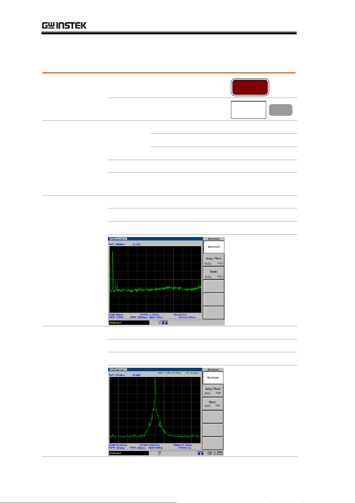
GSP-830 User Manual
Run Autoset
Panel operation
1. Press the Autoset key.
Autoset
2. Press F1 (Autoset).
Search range Amplitude dBm
dBmV
dBuV
Frequency
* These ranges are applicable when both Amplitude floor
0kHz to 3.0GHz
80 to +20dBm
33.01to+66.99dBmV
+26.99to+126.99dBuV
(F2) and Span limit (F3) are set to Auto.
Example: before
Autoset
Start frequency: 0kHz Stop frequency: 3GHz
Span: 3GHz Signal peak: 100MHz
Center frequency: 1.5GHz Reference level: 30dBm
Autoset
F 1
Example: after
Autoset
60
Start frequency: 97.5MHz Stop frequency: 102.5MHz
Span: 5MHz Signal peak: 100MHz
Center frequency: 100MHz Reference level: 30dBm
Page 61

AUTOSET
RBW/VBW/Sweep
after Autoset
All the three BW related parameters, RBW, VBW, and
Sweep, will be reset to Auto mode when using Autoset,
regardless of their previous settings.
Limit vertical search range
Background
Panel operation
You can set the amplitude floor so that the signals lower
than the setting will be ignored by the Autoset search.
Press the Autoset key.
1.
2. Press F2 (Amp. Floor) to switch
the range from Auto (whole
range) to manual (limited range).
3. Enter the amplitude in dB using
the Numerical keys and dB or
Enter key. The Command
window shows the setting.
Autoset
Amp.Floor
Auto Man
GHz /
dB
Sec
MHz /
mSec
kHz /
Enter
Sec
μ
BK SP
Amp. : -30dBm
F 2
Range dBm
dBmV
dBuV
See page50 for selecting amplitude units.
80 to +20dBm, 0.1dB resolution
33.01 to +66.99dBmV, 0.01dB resolution
+26.99 to +126.99dBuV, 0.01dB resolution
Limit horizontal view range
Background
Panel operation
You can change the frequency span limit in the display to
get a better view of the Autoset result. By default, the
frequency span after Autoset is set at 3MHz (Auto).
Press the Autoset key.
1.
2. Press F3 (Span) to switch the
range between Auto (3MHz
fixed limit) to Manual.
3. Enter the frequency using the
Numerical and Unit keys.
Autoset
Span
Auto Man
GHz /
dB
Sec
MHz /
mSec
kHz /
Enter
μ
Sec
BK SP
Span : 10MHz
F 3
Range
Zero span, 2kHz to 3GHz (Manual) 3MHz fixed (Auto)
61
Page 62

GSP-830 User Manual
MARKER
A Marker shows the frequency and amplitude of a
waveform point. The GSP-830 can activate up to 5
markers or marker pairs simultaneously. The marker table
helps editing and viewing multiple markers in a single
display. You can also enable/disable all markers at once.
A delta marker shows the frequency and amplitude
differences between the reference marker. The GSP-830
can automatically move a marker to various locations
including peak signal, center frequency, and start/stop
frequency. More marker operations regarding signal
peaks are also available in the Peak Search function.
Activate
Marker(s)
Move Marker(s)
Activate normal ma
Activate all 5 normal markers at once ................... 64
Activate delta marker............................................. 64
Move marker man
Move marker to highest peak ................................ 65
rker ......................................... 63
ually .......................................... 65
Move marker and highest peak to center............... 66
Move marker to various locations ......................... 66
Move marker to trace ............................................ 67
Marker Table
62
Show Markers in T
able........................................... 67
Page 63

MARKER
Activate/de-activate marker
Range Normal
marker
5
Delta
5 pairs
marker
Amplitude
120 to +20dBm, 0.1dB resolution
73.01 to +66.99dBmV, 0.01dB resolution
13.01 to +126.99dBuV, 0.01dB resolution
Frequency
0kHz to 3GHz
Activate normal marker
Panel operation
1. Press the Marker key.
2. Press F1 (Marker) repeatedly
to select the marker ID from 1
to 5.
3. Press F2 (On) and turn On
the selected marker.
4. Make sure Normal is selected
in F3. If necessary, press F3
and select it.
Marker
Marker
2 3 4 5
1
On Off
F 1
F 2
Display
5. Repeat the above steps for the
number of markers required.
The upper right corner of the display shows the active
marker.
Marker ID, Frequency, Amplitude
63
Page 64

GSP-830 User Manual
Activate all 5 normal markers at once
Panel operation
1. Press the Marker key.
Marker
Display
2. Press F6 (More).
3. Press F3 (All Mkrs On) to turn
On all 5 normal markers.
4. To view all marker status, press
F2 (Marker Table On). The
More
All Mkrs
Off
On
Marker Table
On Off
F 6
F 3
F 2
frequency and the amplitude of
the markers appear in table list.
The marker table shows all 5 marker frequencies and
amplitudes.
Activate delta marker
Panel operation
Display
1. Press the Marker key.
2. Press F1 (Marker) repeatedly
to select the marker ID from 1
to 5.
3. Press F2 (On) and turn on the
selected marker.
4. Make sure Mkr is selected in
F3. If necessary, press F3 and
select Mkr.
5. Repeat the above steps for the
number of markers required.
The upper right corner of the display shows the active
delta marker pair.
Marker
Marker
1
2 3 4 5
On Off
F 1
F 2
64
Page 65

MARKER
Move marker
This section assumes at least one marker is already
activated (page63). Marker frequency positions can be set
ually, or can be automatically positioned at specific
man
locations using the menu shortcuts.
Move marker manually
Panel operation
1. Check the active marker at the
top right corner of the display.
2. Move the marker using the
Left/Right keys and Scroll
knob, or directly enter the
frequency using the Numerical
and Unit keys.
Move marker to highest peak
Method 1
Method 2
1. Check the active marker at the
top right corner of the display.
2. Press the Marker key.
3. Press F4 (To Peak).
1. Alternatively, press the Peak
Search key.
2. Press F1 (Pk Search).
GHz /
Sec
MHz /
mSec
kHz /
μ
Sec
BK SP
Marker
To Peak
Peak Search
Pk Search
dB
Enter
F 4
F 1
Method 3 (marker
tracked to the peak)
1. Another method moves marker
to the peak and also tracks it.
Peak Search
Press the Peak Search key.
2. Press F6 (More).
3. Press F4 and select Track On.
The marker is tracked to the
More
Track
On
Off
F 6
F 4
peak.
4. The peak tracking icon appears
at the bottom of the display.
65
Page 66

GSP-830 User Manual
Move marker and highest peak to center
Method 1
1. Check the active marker at the
top right corner of the display.
2. Press the Marker key.
3. Press F4 (To Peak). The marker
moves to the signal peak.
4. Press F5 (Mkr→Center). The
signal peak moves to the center.
Method 2
1. Alternatively, press the Peak
Search key.
2. Press F5 (Mkr→Center). The
signal peak moves to the peak,
then to the display center.
Move marker to various locations
Panel operation
1. Check the active marker at the
top right corner of the display.
2. Press the Marker key.
Marker
To Peak
Mkr Center
Peak Search
Mkr Center
Marker
F 4
F 5
F 5
3. Press F6 (More).
More
F 6
4. Press F4 (Mkr to...)
Mkr to...
F 4
5. Select the destination and press
F1 (Center) to F5 (Ref Lvl).
Mkr Center
F 1
Center: center frequency
Start: start frequency
Mkr Start
F 2
Stop: stop frequency
CF Step: set the marker
Mkr Stop
F 3
frequency as the frequency step
value
Mkr CFStep
F 4
Ref Lvl: reference amplitude
level
6. Press F6 (Return) to go back to
the previous menu.
Mkr Ref Lvl
Return
F 5
F 6
66
Page 67

MARKER
Move marker to trace
Panel operation
1. Check the active marker at the
top right corner of the display.
Range Auto
Tra ce A
Tra ce B
Tra ce C
2. Press the Marker key.
3. Press F6 (More).
4. Press F1 (Marker Trace).
The marker moves to the active signal/trace.
The marker moves to TraceA.
The marker moves to TraceB.
The marker moves to TraceC.
Show Markers in Table
Panel operation
1. Check the active marker at the
top right corner of the display.
2. Press the Marker key.
Marker
More
Marker Trace
Auto A B C
Marker
F 6
F 1
Display
3. Press F6 (More).
More
4. Press F2 (Marker Table On).
Marker Table
On Off
5. The marker ID, frequency, and amplitude list
appears in the lower half of the display, updated in
real time.
F 6
F 2
67
Page 68

GSP-830 User Manual
PEAK SEARCH
The Peak search function automatically locates signal
peaks in various conditions, such as in next highest peak
and minimum peak. The Peak Search overlaps its feature
with the Marker function, and it is best to use the two
together. All peaks can be viewed at once using the peak
table, with configurable amplitude threshold and sorting
order.
Search Signal
Peaks
Show Peak Table
Search signal peak ................................................. 69
Search next highest peak ....................................... 70
Search highest peak and move to center ............... 70
Search minimum amplitude .................................. 71
Activate peak table................................................. 71
Set peak threshold ................................................. 72
Sort peak ............................................................... 72
68
Page 69

PEAK SEARCH
Search Signal Peak
Peak Search puts a marker on the target signal peak. If no marker has been
activated, the GSP-830 automatically activates marker 1. The peak signal
frequency and amplitude appear at the top right corner of the display.
Marker ID, Frequency, Amplitude
Search signal peak
Method 1
Method 2
Method 3 (marker
tracked to the peak)
1. Press the Peak Search key.
2. Press F1 (Pk Search).
1. Make sure that the marker is
2. Press F4 (To Peak).
1. Another method continuously
2. Press F6 (More).
already activated. If not, press
the Marker key.
tracks the peak signal. Press the
Peak Search key.
Peak Search
Pk Search
Marker
To Peak
Peak Search
More
F 1
F 4
F 6
3. Press F4 (Track On). The
marker is tracked to the peak
Track
On
Off
F 4
signal.
4. The peak tracking icon appears
at the bottom of the display.
69
Page 70

GSP-830 User Manual
Search next highest peak
The marker keeps moving to the next highest peak, in descending order.
Panel operation
1. Press the Peak Search key.
Peak Search
Display
2. Press F2 to F4 repeatedly.
Next Peak moves the marker
to the next highest peak.
Next Pk Right moves the
marker to the next highest
peak on the right side (higher
frequency).
Next Pk Left moves the
marker to the next highest
peak on the left side (lower
frequency)
F4 F3
F2
Next Peak
Next Pk
Right
Next Pk
Left
F 2
F 3
F 4
Search highest peak and move to center
Method 1
Method 2
1. Press the Peak Search key.
2. Press F1 (Pk Search).
1. Make sure that the marker is
already activated. If not, press
the Marker key.
2. Press F4 (To Peak).
3. Press F5 (Mkr→Center).
Peak Search
Mkr Center
Marker
To Peak
Mkr Center
F 5
F 4
F 5
70
Page 71

PEAK SEARCH
Search minimum amplitude
Panel operation
1. Press the Peak Search key.
Peak Search
2. Press F6 (More).
3. Press F5 (Min Search). The
active marker moves to the
deepest valley in the trace.
Minimum Amplitude
Show Peak Table
More
Min Search
F 6
F 5
Activate peak table
Panel operation
1. Press the Peak Search key.
2. Press F6 (More).
3. Press F1 (Peak Table On). The
peak table appears in the lower
half of the display.
Peak Search
More
Peak Table
On
Off
F 6
F 1
Range
10 peaks maximum
71
Page 72

GSP-830 User Manual
Set peak threshold
Only the peaks below the threshold amplitude will be listed in the table.
Panel operation
1. Press the Peak Search key.
Peak Search
2. Press F6 (More).
More
3. Press F1 (Peak Table On).
4. Press F3 (Pk Threshold On).
Peak Table
Off
On
Pk Threshold
On Off
5. A horizontal line appears on the display. The
F 6
F 1
F 3
GSP-830 searches and lists the peaks below this
threshold amplitude.
6. Use the Arrow keys or the
Scroll knob to move the
threshold line.
Sort peak
The peaks are sorted in ascending frequency or descending amplitude order.
Panel operation
1. Press the Peak Search key.
Peak Search
Example: amplitude
sort
2. Press F6 (More).
3. Press F2 (Peak Sort) to switch
between frequency and
amplitude sorting.
More
Peak Sort
Freq Amp
F 6
F 2
72
Page 73

TRACE
TRACE
A Trace keeps track of waveform variants. Three traces,
A, B, and C, are available for accumulating the peak level,
freezing the current waveform shape, and averaging the
waveform. Trace math operations are available using
trace A and B.
Detection modes configure the way the GSP-830
samples the input analog signal for digitizing.
View Trace
Move Trace
Tra ce M at h
Detection Mode
Select (activate) tr
View real-time updated trace (default)................... 74
View peak-hold trace .............................................. 74
Freeze trace............................................................ 75
Hide trace .............................................................. 75
View averaged trace ...............................................75
Move Marker to T
Save/copy/delete/rename trace file .......................77
Run Trace Math...................................................... 78
Select Signal Dete
ace ............................................ 74
race ............................................76
ction Mode ................................ 80
73
Page 74

GSP-830 User Manual
View traced waveform
Select (activate) trace
Panel operation
1. Press the Trace key.
Trace
2. Press F1 (Trace) repeatedly to
select the trace.
Range A (green)
The default trace which is always
activated. Together with trace B, runs
trace math operation (page78).
B (amber)
Together with trace A, runs trace math
operation (page78).
C (yellow)
View real-time updated trace (default)
Background
Panel operation
The trace is updated at every sweep. The old trace is
cleared up and a new trace is drawn on the display
according to the latest measurement.
1. Press the Trace key.
2. Press F2 (Clear).
Trace
A B
Clear
C
Trace
F 1
F 2
3. The clear mode icon appears at
the bottom of the display.
View peak-hold trace
Background
Panel operation
74
In the peak hold mode, the amplitude of the new trace
is compared with the last one at each sweep. Only the
higher amplitude replaces old trace points, thus holding
the highest (peak) value.
1. Press the Trace key.
2. Press F3 (Peak Hold).
Trace
Peak Hold
F 3
Page 75

TRACE
Display
Freeze trace
Panel operation
3. The peak hold trace icon
appears at the bottom of the
display.
Peak Hold
Clear
(default)
1. Press the Trace key.
Trace
2. Press F4 (View). The trace
shape and location becomes
fixed.
3. The view mode (freeze) icon
appears at the bottom of the
display.
Hide trace
Panel operation
1. Press the Trace key.
2. Press F5 (Blank). The trace
disappears from the display.
3. To bring back the trace again,
press F2 (Clear).
View averaged trace
Panel operation
(Method1)
1. Press the Trace key.
View
Trace
Blank
Clear
Trace
F 4
F 5
F 2
2. Press F6 (More).
More
75
F 6
Page 76

GSP-830 User Manual
Panel operation
(Method2)
Range
Example: after
average
3. Press F1 (AVG On) to turn on
the average mode.
4. The average mode icon appears
at the bottom of the display.
5. Enter the average number using
the Numerical keys and Enter
key.
1. Press the BW key.
2. Press F4 (AVG On) to turn on
averaging.
3. Enter the average time using the
numerical keys and Enter key.
1 to 200
Averaged 20 times
On
20
On
20
AVG
Off
BW
AVG
Off
F 1
GHz /
dB
Sec
MHz /
mSec
kHz /
Enter
μ
Sec
BK SP
F 4
GHz /
dB
Sec
MHz /
mSec
kHz /
Enter
μ
Sec
BK SP
Move Marker to Trace
Panel operation
Range Auto
76
1. Check the active marker at the
top right corner of the display.
2. Press the Marker key.
3. Press F6 (More).
4. Press F1 (Marker Trace).
The marker moves to the active signal
or trace.
Marker
More
Marker Trace
Auto A B C
F 6
F 1
Page 77

TRACE
Tra ce A
Tra ce B
Tra ce C
The marker moves to TraceA.
The marker moves to TraceB.
The marker moves to TraceC.
Display Marker on TraceC
Save/copy/delete/rename trace file
Background
Trace files can be saved, copied,
deleted, or renamed using the file
utility. Press the File key to access
each function.
File
Save/Copy
Delete
Rename
Press F1 (Copy). For detailed steps,
see page115.
Press F2 (Delete). For detailed steps,
see page118.
Press F3 (Rename). For detailed
steps, see page120.
Copy...
Delete...
Rename...
F 1
F 2
F 3
77
Page 78

GSP-830 User Manual
Run Trace Math
Background
Various mathematical operations are available using
trace A and trace B. Both traces have to be activated in
advance (page74). After the math operation, the trace
mode c
hanges into the View mode (page75).
Panel operation
1. Press the Trace key.
2. Press F6 (More).
3. Press F2 (Trace Math).
4. Select and press the type of
math operation from F1 to F5.
A↔B: Swaps trace A and B.
A+B→A: Adds trace A and B.
A−B→A: Subtracts trace B
from trace A.
A+const→A: Adds a constant
value to trace A.
A−const→A: Subtracts a
constant value from trace A.
5. When A+const / A−const are
selected, enter the constant
value using the Numerical keys
and dB or Enter key.
Range: 40 to +40dB
Trace
More
Trace Math..
A B
A+B A
A-B A
A+const A
A-const A
GHz /
dB
Sec
MHz /
mSec
kHz /
Enter
μ
Sec
BK SP
F 6
F 2
F 1
F 2
F 3
F 4
F 5
Example: A↔B
78
6. The trace math icon appears at
the bottom of the display.
Page 79

TRACE
Example: A+B→A
Example: A−B→A
Example: A+constant→A (5 dB)
Example: A−constant→A (5 dB)
79
Page 80

GSP-830 User Manual
Select Signal Detection Mode
Background
In order to show the incoming signal on the display, the
GSP-830 first converts the input signal to a video signal,
digitizes it, then uses a detector to pick up the samples
for display. By configuring the detection mode, certain
signals can be viewed more clearly and/or sharply.
Panel operation
1. Press the Trace key.
2. Press F6 (More).
3. Press F3 (Detection).
4. Select the signal detection type
from F1 to F5 and press it. See
below for the description of
each type.
5. Press F6 (Return) to go back to
the previous menu.
Trace
More
Detection..
Normal
Sample
Peak+
AVG
QPeak
Return
F 6
F 3
F 1
F 2
F 3
F 4
F 5
F 6
Parameter Normal
The default mode. When the signal level is
constantly increasing or decreasing, the
positive peaks are detected. Otherwise,
detecting mode switches between positive
peak and negative peaks. Useful for
picking up burst phenomenon while
avoiding excessive noise.
Sample
Detects signals randomly. Useful when
detecting noise-like signals, but tends to
miss burst phenomenon.
Peak+
(positive
peak)
Detects positive peak signals. Useful for
detecting sinusoid signals, but tends to
pick up more noise than other modes.
80
Page 81

TRACE
AVG
(average)
Available when the optional EMI filter is
installed. Detects the average power level
of the samples using low pass filter.
Useful for reducing the noise level. For
EMI filter details, see page146.
QPeak
(quasi-peak)
Available when the optional EMI filter is
installed. Detects the quasi-peak power
level of the samples. Useful for viewing in
zero span without missing signal
variations. For EMI filter details, see
page146.
Example Normal detection mode
Sample detection mode
Peak+ detection mode
81
Page 82

GSP-830 User Manual
POWER MEASUREMENT
The Power Measurement function includes four types
of frequently used complex measurement procedures:
ACPR, OCBW, N dB, and Phase Jitter. Each item is
configurable and updated in real-time.
ACPR
OCBW
N dB
Phase Jitter
Overview................................................................ 83
ACPR measurement step ....................................... 83
Overview................................................................ 86
OCBW measurement step...................................... 86
N dB Measurement
Phase Jitter Measur
................................................ 88
ement...................................... 89
82
Page 83

POWER MEASUREMENT
ACPR Measurement
Overview
Background
ACPR (Adjacent Channel Power Ratio), or ACLR
(Adjacent Channel Leakage Ratio), refers to the amount
of leakage power coming from the main radio channel
which affects adjacent channels as signal distortion.
Parameter Channel
bandwidth
The frequency bandwidth the target
channel occupies.
Range: 0kHz to Current span
Channel space
The frequency distance between each
main channel.
Range: 0kHz to 3GHz
Adjacent channel
bandwidth 1 & 2
The frequency bandwidth the
adjacent channels occupy.
Range: 1kHz to 3GHz
Adjacent channel
offset 1 & 2
The frequency distance between the
adjacent channels and main channel.
Range: 1kHz to 3GHz
ACPR measurement step
1. Activate ACPR
1. Press the Measurement key.
2. Press F2 (ACPR On).
Meas
ACPR
On
Off
F 2
3. The display switches to ACPR mode, updating the
ACPR results in the lower half of the display.
Lower
ACPR 1
Upper
ACPR 1
Lower
ACPR 2
Upper
ACPR 2
83
Page 84

GSP-830 User Manual
2. Set channel BW
3. Set adjacent
channel1
bandwidth
1. Press F1 (Channel Setup).
2. Press F1 (CH BW).
3. Enter the channel BW using the
Numerical and Unit keys.
Channel
Setup...
CH BW
GHz /
Sec
MHz /
mSec
kHz /
μ
Sec
BK SP
F 1
F 1
dB
Enter
Range: 0kHz to Current span
4. The value is updated in the
Channel BW column in MHz.
Note: • If the span (page43) becomes less than the
CHBW setting, the warning “Span is less than
CHBW!” appears in the command window.
• If the CHBW is 0kHz, the warning “CHBW is
zero!” appears in the command window.
1. Press F4 (ADJ CH Offset).
ADJ CH
Offset...
F 4
4. Set adjacent
channel1
offset
2. Press F1 (Adj CH BW1).
3. Enter the adjacent channel 1
bandwidth using the Numerical
and Unit keys.
Range: 1kHz to 3GHz
4. The value is updated in the Adj
CH BW1 column in MHz.
1. Press F2 (Adj CH Offs1).
2. Enter the adjacent channel1
offset using the Numerical and
Unit keys.
Range: 1kHz to 3GHz
3. The value is updated in the Adj
CH Offset1 column in MHz.
Adj CH BW1
GHz /
dB
Sec
MHz /
mSec
kHz /
Enter
μ
Sec
BK SP
Adj CH Offs1
GHz /
dB
Sec
MHz /
mSec
kHz /
Enter
μ
Sec
BK SP
F 1
F 2
5. Set adjacent
channel2
bandwidth
84
1. Press F3 (Adj CH BW2).
Adj CH BW2
F 3
Page 85

POWER MEASUREMENT
GHz /
dB
Sec
2. Enter the adjacent channel2
bandwidth using the Numerical
MHz /
mSec
kHz /
Enter
μ
Sec
BK SP
and Unit keys.
Range: 1kHz to 3GHz
6. Set adjacent
channel2
offset
7. Set channel
space
3. The value is updated in the Adj
CH BW2 column in MHz.
1. Press F4 (Adj CH Offs2).
2. Enter the adjacent channel 2
offset using the Numerical and
Unit keys.
Range: 1kHz to 3GHz
3. The value is updated in the Adj
CH Offset2 column in MHz.
1. Press F2 (Channel SPC).
2. Enter the channel space using
the Numerical and Unit keys.
Range: 0kHz to 3GHz
3. The value is updated in the
Channel Space column in MHz.
Adj CH Offs2
GHz /
dB
Sec
MHz /
mSec
kHz /
Enter
μ
Sec
BK SP
CH SPC
GHz /
dB
Sec
MHz /
mSec
kHz /
Enter
μ
Sec
BK SP
F 4
F 2
8. Move channel
up/down
1. Press F6 (Return) twice.
2. Press F4 (CH Up) or F5 (CH
Down) to switch the
measurement to the next
channel.
Return
x2
CH Up
CH Down
F 6
F 4
F 5
85
Page 86

GSP-830 User Manual
OCBW Measurement
Overview
Background
OCBW (OCcupied BandWidth) refers to the bandwidth
of the channel that consumes (occupies) the specified
amount of power.
Parameter Channel
bandwidth
The frequency bandwidth that the
target channel occupies.
0kHz to Current span
Channel space
The frequency distance between each
main channel.
0kHz to 3GHz
OCBW %
The ratio of occupied bandwidth as
the amount of power consumed.
0% to 100%, 0.1% resolution
OCBW measurement step
1. Activate OCBW
1. Press the Measurement key.
2. Press F3 (OCBW On).
3. The display switches to OCBW mode, updating the
OCBW result in the lower half of the display.
Meas
OCBW
On
Off
F 3
2. Set channel BW
86
1. Press F1 (Channel Setup).
Channel
Setup...
OCBW
CH
Power
F 1
Page 87

POWER MEASUREMENT
4. Set OCBW %
2. Press F1 (CH BW).
3. Enter the channel BW using the
Numerical and Unit keys.
CH BW
MHz /
μ
Sec
BK SP
F 1
GHz /
dB
Sec
mSec
kHz /
Enter
Range: 0kHz to Current span
4. The value is updated in the
Channel BW column in MHz.
Note: • If the span (page43) becomes less than the
CHBW setting, the warning “Span is less than
CHBW!” appears in the command window.
• If the CHBW is 0kHz, the warning “CHBW is
zero!” appears in the command window.
1. Press F3 (OCBW %).
2. Enter the OCBW % using the
Numerical keys and Enter key.
Range: 0% to 100%
OCBW %
GHz /
Sec
MHz /
mSec
kHz /
μ
Sec
BK SP
F 3
dB
Enter
3. Set channel space
5. Move channel
up/down
3. The value is updated in the
OCBW % column.
1. Press F2 (Channel SPC).
2. Enter the channel space using
the Numerical and Unit keys.
Range: 0kHz to 3GHz
3. Space column updates the value
in MHz.
1. Press F6 (Return) twice.
2. Press F4 (CH Up) or F5 (CH
Down) to switch the
measurement to the next
channel.
CH SPC
GHz /
Sec
MHz /
mSec
kHz /
μ
Sec
BK SP
Return
CH Up
CH Down
F 2
dB
Enter
F 6
F 4
F 5
87
Page 88

GSP-830 User Manual
N dB Measurement
Background
N dB refers to the frequency bandwidth of a channel
that covers the specified amplitude.
Parameter N dB
1. Activate N dB
1. Press the Measurement key.
2. Press F6 (More).
3. Press F1 (N dB BW On).
4. The display switches to N dB
mode, updating N dB result in
the lower half of the display.
0.1dB to 80dB, 0.1dB resolution
Meas
More
N dB BW
On
Off
3dB
Bandwidth
F 6
F 1
2. Set amplitude
88
1. Press F2 (NdB) to set the
amplitude which the BW covers.
2. Enter the amplitude using the
Numerical keys and dB or Enter
key.
Range: 0.1dB to 70dB
N dB
F 2
GHz /
dB
Sec
MHz /
mSec
kHz /
Enter
μ
Sec
BK SP
Page 89

POWER MEASUREMENT
Phase Jitter Measurement
Background
Phase Jitter refers to the amount of phase fluctuation
that leads to shortening or lengthening the center
frequency.
Parameter Start offset
Beginning frequency offset in reference to
the center frequency.
0kHz to ½ of span, 0.1MHz resolution
Stop offset
End frequency offset in reference to the
center frequency.
0kHz to ½ of span, 0.1MHz resolution
1. Activate Phase
Jitter
1. Press the Measurement key.
2. Press F6 (More).
3. Press F3 (Phase Jitter On). Phase Jitter
4. The display switches to Phase jitter mode, updating
Phase jitter result in the lower half of the display.
Meas
More
On Off
Phase
fluctuation
Time
fluctuation
F 6
F 3
2. Set start/stop
offset
1. Press F4 (Phase Jitter Setup).
2. Press F1 (Start Offset) and F2
(Stop Offset) to set the amount
of the beginning and end offset.
3. Enter the offset using the
Numerical/Unit keys.
Phase Jitter
Setup
Start
Offset
Stop
Offset
GHz /
Sec
MHz /
mSec
kHz /
μ
Sec
BK SP
F 4
F 1
F 2
dB
Enter
Range: 0kHz to ½ of span
89
Page 90
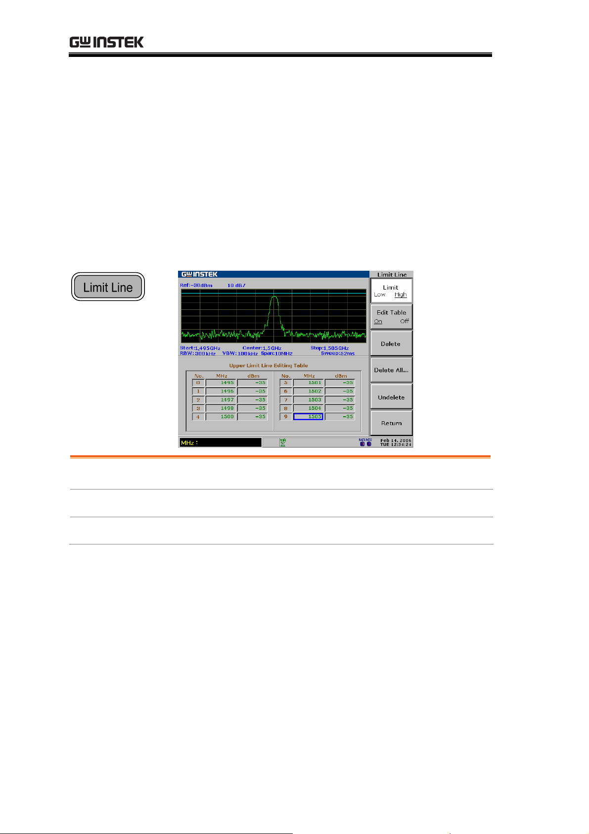
GSP-830 User Manual
LIMIT LINE
A Limit Line sets the upper and lower amplitude limit
over the entire frequency range. Limit lines can be used
to detect whether the input signal level is above, below,
or within the specified amplitude. The result, pass or fail,
is shown at the bottom of the display in real-time.
Edit
Pass/Fail Test
Limit Line File
Edit Limit
Run Pass/Fail test.................................................. 94
Save/copy/delete/rename limi
Line ....................................................... 91
t line file................. 94
90
Page 91

LIMIT LINE
Edit Limit Line
Parameters Editing point
Maximum 10 points for each limit line,
high or low.
Frequency
Amplitude
9kHz to 3GHz per editing point.
Per editing point:
130 to +20dBm
83.01dBmV to +66.99dBmV
23.01dBuV to +126.99dBuV
1. Activate Limit
Line
1. Press the Limit Line key.
2. Press F1 (H Limit On) and/or
F2 (L Limit On) to activate the
high and/or low limit line.
3. The limit line appears on the
display.
Blue: H limit line
Yellow: L limit line
Limit Line
H Limit
On Off
L Limit
On
Off
F 1
F 2
2a Activate limit
line editing table
1. Press F3 (Edit).
2. Press F1 (Limit) to select the
limit line to be edited.
3. Press F2 (Edit Table On). The
editing table appears in the
lower half of the display.
Edit...
Limit
Low High
Edit Table
On
Off
H Limit
Line
(edited)
L Limit
Line
F 3
F 1
F 2
91
Page 92
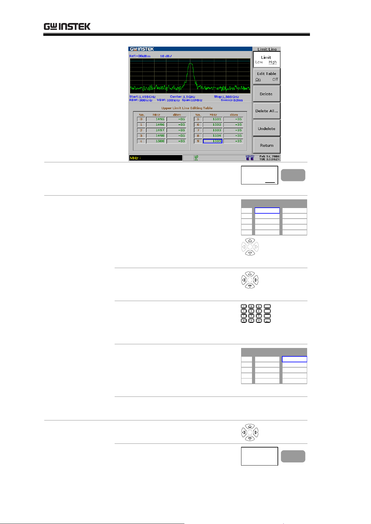
GSP-830 User Manual
2b Deactivating
limit line table
3a. Add a limit line
point
Press F2 (Edit Table Off). The
editing table disappears and the
edited contents will be saved.
1. Make sure that the cursor is
pointing to the first empty
frequency point. Use the
Up/Down keys to move the
cursor, if necessary.
10 points are available for each
high and low limit line.
Edit Table
On Off
No. MHz dBm
1
2
3
4
5
F 2
3b. Delete a limit
line point
2. If necessary, move the cursor to
different frequency points using
the Arrow keys.
3. Enter the frequency using the
Numerical and Unit keys.
Range: 9kHz to 3GHz
The value is displayed in MHz.
4. The cursor automatically moves
to the dBm side. Enter the gain
in using the Numerical keys and
dB or Enter key.
Range: 130dBm to +20dBm
5. Continue the above steps for
the number of points required.
1. Move the cursor using the
Arrow keys.
2. Press F3 (Delete) to delete the
point (frequency and amplitude
together).
GHz /
dB
Sec
MHz /
mSec
kHz /
Enter
μ
Sec
BK SP
No. MHz dBm
1
2
3
4
5
98
Delete
F 3
92
Page 93

LIMIT LINE
No. MHz dBm
1
2
3
4
5
98
100
102
3. To undo deletion, press F5
(Undelete).
3c. Delete the whole
limit line data
1. Press F4 (Delete All).
2. Press F1 (No) or F2 (Yes) to
confirm deletion. All 10 limit
line points will be deleted at
once.
3. Press F6 (Return) to go back to
the previous menu.
4. To undo deletion, press F5
(Undelete).
-40
-30
-40
No. MHz dBm
1
2
3
4
5
Undelete
Delete All..
Undelete
98
102
No
Yes
Return
-40
-40
F 5
F 4
F 1
F 2
F 6
F 5
4. Switch
upper/lower
limit line
If necessary, press F1 (Limit) to
start editing the other limit line.
Repeat the above steps.
Limit
Low High
Example High Limit Line
Point No. Frequency (MHz) Amplitude (dBm)
1 98MHz 40dBm
2 100MHz 30dBm
3 102MHz 40dBm
Resulted line
F 1
93
Page 94

GSP-830 User Manual
Run Pass/Fail test
This section assumes that the limit line is already defined.
Pass/Fail condition
Checks whether the entire waveform
amplitude stays between the high limit
and low limit lines.
1. Select condition
2. Run Pass/Fail test
Note
Checks whether the peak waveform
amplitude stays between the high and
low limit lines.
Checks whether the waveform valleys
stay between the high and low limit
lines.
1. Press the Limit Line key.
2. Press F5 (Pass/Fail)
repeatedly to select the
Limit Line
Pass/Fail
F 5
condition.
1. Press F4 (Pass/Fail On) to
activate the test.
Pass/Fail
On
Off
F 4
2. The test result appears at the
bottom of the display.
If the limit lines are not defined, the Pass/Fail test uses
the highest or lowest display level as the limit line.
Save/copy/delete/rename limit line file
Background
Save/Copy
Delete
Rename
94
Limit line files can be saved, copied,
deleted, or renamed using the file
utility. Press the File key to access
each function.
Press F1 (Copy). For detailed steps,
see page115.
Press F2 (Delete). For detailed steps,
see page118.
Press F3 (Rename). For detailed
steps, see page120.
File
Copy...
Delete...
Rename...
F 1
F 2
F 3
Page 95

BANDWIDTH
BANDWIDTH
The BW (BandWidth) feature configures how narrow
the GSP-830 can sort out different signal peaks
(resolution), and how fast the display can be updated
(sweep time). Averaging the waveform is also available
for smoothing noise level. The resolution, sweep time,
and averaging are in a trade-off relationship, so
configuration should be done with care.
BW
RBW/VBW
Sweep Time
Average
Reset
Select RBW (Resolution B
Select VBW (Video BandWidth) .............................98
RBW/VBW Auto Mode Contents ............................99
Set Sweep time
Average Waveform................................................ 101
Reset RBW/VBW/sweep time to auto
.....................................................101
andWidth)......................96
...................102
95
Page 96

GSP-830 User Manual
Select RBW (Resolution BandWidth)
Background
RBW (Resolution Bandwidth) defines the width of the
IF (intermediate frequency) filter that is used to separate
signal peaks from one another. The narrower the RBW,
the greater the capability to separate signals at close
frequencies. But it also makes the sweep time longer
under specific frequency span (the display is updated
less frequently). See page99 for suitable RBW selection.
Panel operation
1. Press the BW key.
2. Press F1 (RBW) to select Auto
or Manual.
3. When Man (manual) is selected,
use the Arrow keys or Scroll
knob to select the RBW. The
BW
RBW
Auto
Man
RBW: 30kHz
F 1
selected RBW appears in the
command window.
Mode Auto
RBW is automatically selected. See
page99 for the setting.
Manual
RBW is manually selected. The BW icon
appears at the bottom of the display.
Range
See page99 for RBW reference setting according to the
frequency span.
RBW Recommended span Standard/ Optional
300Hz
3kHz
9kHz
10kHz
30kHz
Span<30kHz Optional (300Hz
Span<300kHz Standard
300kHzSpan<600kHz Optional (EMI
300kHzSpan<1MHz Optional (10k/
300kHzSpan<6MHz Standard
96
RBW)
Filter - page146)
100kHz RBW)
Page 97

BANDWIDTH
100kHz
120kHz
300kHz
4MHz
Check RBW
installation status
1. Press the System key.
2. Press F6 (More).
3. Press F4 (System Config On) to
6MHzSpan<20MHz Optional
6MHzSpan<19MHz Optional (EMI
6MHzSpan<60MHz Standard
60MHzSpan Standard
show the system configuration
in the display.
(10k/100kHz
RBW)
Filter – page146)
System
More...
System Config
On Off
F 6
F 4
Note
Optional
Items
4. Check the optional items
corner and see the RBW
installation status (checkmark
– installed, blank – not
installed)
Installed
Not installed
5. Press F4 (System Config Off)
to close the system
System Config
On Off
F 4
configuration.
9k/120kHz RBW (EMI Filter) and 10k/100kHz RBW
are exclusive; cannot be installed together. For installing
a new optional RBW, contact the service center.
97
Page 98

GSP-830 User Manual
Select VBW (Video BandWidth)
Background
VBW (Video Bandwidth) defines the smoothness of the
trace on the display. Combined with RBW, VBW defines
the ability to sort out target signal from surrounding
noise or adjacent peaks.
See page99 for suitable VBW selection.
Panel operation
1. Press the BW key.
2. Press F2 (VBW) to select Auto
or Manual.
3. When Man (manual) is selected,
use the Arrow keys or Scroll
knob to select the VBW. The
selected VBW appears in the
command window.
Mode Auto
VBW is automatically selected. See
page99 for setting.
Manual
VBW is manually selected. The VBW
icon appears at the bottom of the
Range
10Hz to 1MHz in 1-3 steps
display.
In Auto mode, VBW is automatically selected in
combination with RBW. See page99 for the settings. Use
uto mode settings for reference when manually
the A
selecting the VBW.
BW
VBW
Man
Auto
VBW: 1kHz
F 2
Note
98
The GSP-830 automatically changes the VBW
according to RBW selection.
Page 99

BANDWIDTH
RBW/VBW Auto Mode Contents
Background
• The following applies when selecting Auto mode for
RBW and VBW setting. Use them as a reference when
manually selecting RBW and VBW.
• The RBW/VBW range differs according to system
configuration, especially the optional items.
Check the RBW
installation status
1. Press the System key.
2. Press F6 (More).
3. Press F4 (System Config On) to
turn on the system
configuration window.
System
More...
System Config
On Off
F 6
F 4
Optional
Items
4. Press F4 (System Config Off) to
close the system configuration.
System Config
On Off
F 4
Optional item Install Icon Standard
configuration
EMI Filter(9k/120k RBW) No
300Hz RBW No
10k/100kHz RBW No
(Logarithmic scale, unit in Hz)
VBW
RBW
Span
0
10k
3k
10k 300k
30k 4M
300k 6M 60M 3G
100k
300k
99
Page 100

GSP-830 User Manual
Standard +
9k/120kHz RBW
configuration
10kHz/100kHz RBW No
Standard +
300/9k/120kHz
RBW configuration
10kHz/100kHz RBW No
Optional item Install Icon
EMI Filter (9k/120k RBW) Yes
300Hz RBW No
(Logarithmic scale, unit in Hz)
VBW
RBW
Span
0 19M
10k
10k 300k
10k 30k 100k
30k3k
9k 4M
300k 600k 6M 60M 3G
120k 300k
Optional item Install Icon
EMI Filter (9k/120k RBW) Yes
300Hz RBW Yes
(Logarithmic scale, unit in Hz)
VBW
RBW
3k
10k 10k 300k
3k 9k 4M
10k 30k 100k
30k300
120k 300k
Span
Standard +
10k/100kHz RBW
0 19M
Optional item Install Icon
EMI Filter (9k/120k RBW) No
30k
configuration
300Hz RBW No
10kHz/100kHz RBW Yes
Standard +
300/10k/100kHz
RBW configuration
(Logarithmic scale, unit in Hz)
VBW
RBW
Span
0 20M
10k
Optional item Install Icon
EMI Filter (9k/120k RBW) No
300Hz RBW Yes
10kHz/100kHz RBW Yes
(Logarithmic scale, unit in Hz)
VBW
RBW
3k
300
300k 600k 6M 60M
10k 300k
10k 30k 100k
30k3k
10k 4M
300k 1M 6M 60M
10k
10k 300k
10k 4M
3k
100k 300k
10k 30k 100k
100k 300k
30k
3G
3G
100
Span
0 20M
30k
300k 1M 6M 60M
3G
 Loading...