

Page 1

GRS-6052A/6032A OSCILLOSCOPE
Declaration of Conformity
We
GOOD WILL INSTRUMENT CO., LTD.
No. 7-1, Jhongsing Rd., Tucheng City, Taipei County 236, Taiwan
GOOD WILL INSTRUMENT (SUZHOU) CO., LTD.
No.69 Lushan Road, Suzhou New District Jiangsu, China.
declares that the below mentioned product
GRS-6052A, GRS-6032A
are herewith confirmed to comply with the requirements set out in the Council Directive on
the Approximation of the Law of Member States relating to Electromagnetic Compatibility
(89/336/EEC, 92/31/EEC, 93/68/EEC) and Low Voltage Equipment Directive
(73/23/EEC, 93/68/EEC).
For the evaluation regarding the Electromagnetic Compatibility and Low Voltage
Equipment Directive, the following standards were applied:
◎ EMC
EN 61326-1: Electrical equipment for measurement, control and laboratory use –– EMC
requirements (1997+A1: 1998)
Conducted and Radiated Emission
EN 55011: 1998 Group I class A
Current Harmonic
IEC 61000-3-2: 1995
Voltage Fluctuation
IEC 61000-3-3: 1994
-------------------------
-------------------------
-------------------------
-------------------------
◎ Safety
Low Voltage Equipment Directive 73/23/EEC & amended by 93/68/EEC
Safety Requirements
IEC/EN 61010-1:2001
Electrostatic Discharge
IEC 61000-4-2: 1995
Radiated Immunity
IEC 61000-4-3: 1995
Electrical Fast Transients
IEC 61000-4-4: 1995
Surge Immunity
IEC 61000-4-5: 1995
Conducted Susceptibility
IEC 61000-4-6: 1996
Power Frequency Magnetic Field
IEC 61000-4-8: 1993
Voltage Dips/ Interrupts
IEC 61000-4-11: 1994
USER MANUAL
CONTENTS PAGE
1. PRODUCT INTRODUCTION......................... ........... ........... ..
1-1.Description……………………………………………….
1-2.Feature…………………………………………………....
1
1
2
2. TECHNICAL SPECIFICATIONS………………………… 5
3. PRECAUTIONS BEFORE OPERATION…….…………...
3-1.Unpacking the Oscilloscope……………….…… …….…
3-2.Checking the Line Voltage…………………..…………..
3-3.Environment……………………………………..………
3-4.Equipment Installation and Operati on………………... .
3-5.CRT Intensity……………………………………………
3-6.Withstanding Voltage of Input Termi nals……… ……...
4. PANEL INTRODUCTION……………………..…………...
4-1.Front Panel……………………………………………….
4-2.Rear Panel……………………………………….……….
5. OPERATION METHOD………………………………...….
5-1.Readout Display……………………………………..…...
5-2.Connecting Input Signals..………………………………
5-3.Adjustment and Checks…………………………………
5-4.Function Check…..………………………………………
5-5.Basic Operation………….….…………………………....
5-6.Digital Storage Functions………………………………..
5-7.Measurement Application……………………………….
5-8.RS-232 Interface Remote Control………………………
6. MAINTENANCE……………………………………………
6-1.Fuse Replacement………………………………………..
6-2.Line Voltage Conversion……………………………..….
6-3.Cleaning………………………………………………….
9
9
9
10
10
10
10
11
13
32
34
34
37
38
40
42
51
60
62
94
94
94
95
7. BLOCK DIAGRAM………………………………………... 96
i
i
⎯ ⎯
Page 2

GRS-6052A/6032A OSCILLOSCOPE
GRS-6052A/6032A OSCILLOSCOPE
USER MANUAL
SAFETY TERMS AND SYMBOLS
These terms may appear in this manual or on the product:
WARNING. Warning statements identify condition or practices
that could result in injury or loss of life.
CAUTION. Caution statements identify conditions or practices that
could result in damage to this product or other property.
Measurement category I is for measurements performed on circuits not directly
connected to MAINS.
Measurement category II is for measurements performed on circuits directly
connected to the low voltage installation.
Measurement category III is for measurements performed in the building
installation.
Measurement category IV is for measurements performed at the source of the
low-voltage installation.
The following symbols may appear i n this man ual or on the pr oduct:
USER MANUAL
FOR UNITED KINGDOM ONLY
NOTE: This lead/appliance must only be wired by competent persons
WARNING: THIS APPLIANCE MUST BE EARTHED
IMPORTANT: The wires in this lead are coloured in accordance with the
following code:
Green/ Yellow: Earth
Blue: Neutral
Brown: Live (Phase)
As the colours of the wires in main leads may not correspond with the
colours marking identified in your plug/appliance, proceed as follows:
The wire which is coloured Green & Yellow must be connected to the Earth
DANGER ATTENTION Protective Earth(ground)
High Voltage refer to Manual Conductor Terminal
Terminal
ii
⎯ ⎯
terminal marked with the letter E or by the earth symbol
or col oured
Green or Green & Yellow.
The wire which is coloured Blue must be connected to the terminal which is
marked with the letter N or coloured Blue or Black.
The wire which is coloured Brown must be connected to the terminal
marked with the letter L or P or coloured Brown or Red.
If in doubt, consult the instructions provided with the equipment or contact
the supplier.
iii
⎯ ⎯
Page 3

GRS-6052A/6032A OSCILLOSCOPE
GRS-6052A/6032A OSCILLOSCOPE
USER MANUAL
This cable/appliance should be protected by a suitably rated and approved
HBC mains fuse: refer to the rating information on the equipment and/or
user instructions for details. As a guide, cable of 0.75mm
2
should be
protected by a 3A or 5A fuse. Larger conductors would normally require
13A types, depending on the connection method used.
Any moulded mains connector that requires removal /replacement must be
destroyed by removal of any fuse & fuse carrier and di sposed of immedia tely,
as a plug with bared wires is hazardous if a engaged in live socket. Any rewiring must be carried out in accordance with the information detailed on
this label.
USER MANUAL
1.PRODUCT INTRODUCTION
1-1. Description
The GRS-6052A and GRS-6032A set a standard in performance and economy,
each equips with two professional scopes in one. They can be operated as a real
time 50 or 30MHz analog oscilloscope and become a full function digital storage
oscilloscope by pressing a button. Now, you have the power for digital capture and
analysis of elusive single sho ts with a full 100MS/s sample rate. The i nstruments
provide with a high speed A/D converter for each channel to enable the
measurement, memory, and analysis of high-speed phenomena. A microprocessorbased operating system controls most of the functions of the instrument, including
cursor readout and digitized panel setting. On-screen alphanumeric readout and
cursor function for voltage, time and frequency measurement provide extraordinary
operational convenience. Ten different user defined instrument settings can be
saved and recalled without restriction.
The vertical deflection system has two input channels. Each channel has 14 basic
deflection factors from 1mV to 20V per division. The horizontal deflection system
provides sweep time from 100s to 0.2μs per division. The trigger system provides
stable triggering over the full bandwidth of the vertical deflection system.
iv
⎯ ⎯
1
⎯ ⎯
Page 4

GRS-6052A/6032A OSCILLOSCOPE
GRS-6052A/6032A OSCILLOSCOPE
USER MANUAL
1-2.Features
Additionally, the oscillo scope off ers seve ral othe r feat ures:
1) High intensity and internal graticule CRT
The oscilloscope employs a high intensity 6-inch rectangular type cathoderay tube with red internal graticule. It displays clear readable traces even at
high sweep speeds. Internal graticule lines eliminate parallax-viewing error
between the trace and the graticule line.
2) Multiple Digital Storage Functions
z Digitizing repetitive waveform up to full bandwidth 50/30MHz through
the use of equivalent sampling (500MS/s).
z 2k-word acquisition memory per channel up to 10 sets SAVE/RECALL
reference memories (with back-up) are provided.
z Pre-trigger function for observing waveforms before triggering. The
trigger point can be selected from 0~10 DIV (in 0.02DIV steps).
z Roll mode is ideal for observing flickering low-speed signals. The
TIME/DIV range up to 100s.
z The peak detect mode can detect glitch with pulse duration of 25ns or
more.
z The persistence mode makes for easy measurements of jitter, voltage
variation, and etc.
z The averaging function can be selected freely from 2 to 256. This
effectively reduces noi se fr om repe titive sign al s.
z The smoothing (dot-join) function provides linear connections between
the captured point, ensuring that digitized signals are displayed without
gaps.
z In the magnification mode, the DOT or LINEAR interpolation can be
selected according to the waveform.
USER MANUAL
z The built-in RS-232C interface enables remote control operation and
signal processing via a PC.
z The X-Y mode is same as the real ti me mode. The X (horizontal ) signal is
connected to the input of CH1, the Y (vertical) signal is applied to the
input of CH2, and the storage waveform bandwidth up to 50MHz/30MHz.
3) ALT-MAG Function (both Real Time Mode and Storage Mode)
The primary sweep waveform along with the magnified sweep waveform can
be displayed simultaneously using the ALT-MAG function. The
magnification ratio can be selected from among three stages of ×5, ×10,
×20 for magnifying the displayed waveform in the center of the CRT.
4) Convenient VERT-MODE Triggering
The sync signal source is decided automatically when vertical axis mode is
switched. This means that you need not change the trigger source every time
you switch the VERT-MODE.
5) TV triggering
Exclusive TV sync separa tor circuit technology provides stable TV signal
measurements on fields, frames and lines.
6) Hold Off (Real Time Mode only)
The function allows the obtaining of stable synchronization for even
complex waveforms that are difficult to synchronized by adjusting the
trigger level alone.
7) CH1 Signal Output
The CH1 signal output is obtained by branching the input signal in the
middle of the signal line. As the connector outputs the input signal at a rate
of 50mV/DIV, connecting a frequency counter makes it possible to measure
the frequency of a very low signa l while ob serving it s wavef orm.
2
⎯ ⎯
3
⎯ ⎯
Page 5
GRS-6052A/6032A OSCILLOSCOPE
GRS-6052A/6032A OSCILLOSCOPE
USER MANUAL
8) Z-axis intensity modulation (Real Time Mode only)
For applying a blanking signal from an external source. The trace displayed
on the screen may be intensity-modulated where pulse signal or time-scale
marks are required.
9) LED indicator and buzzer alarm
The LED’s located in the front panel assist operation and indicated
additional information. Incorrect operation and the electrical end position of
control knobs are indicated by a warning beep.
10) SMD manufacturing technology
The instrument is built by using the most advanced SMD technology so as to
reduce the number of internal wiring and shorten the foil route on the pc
board. This will also greatly increase the high frequency performance and the
reliability of the product.
11) Compact size (275W×130H×370D) mm and front panel layout groups for easyto-use.
USER MANUAL
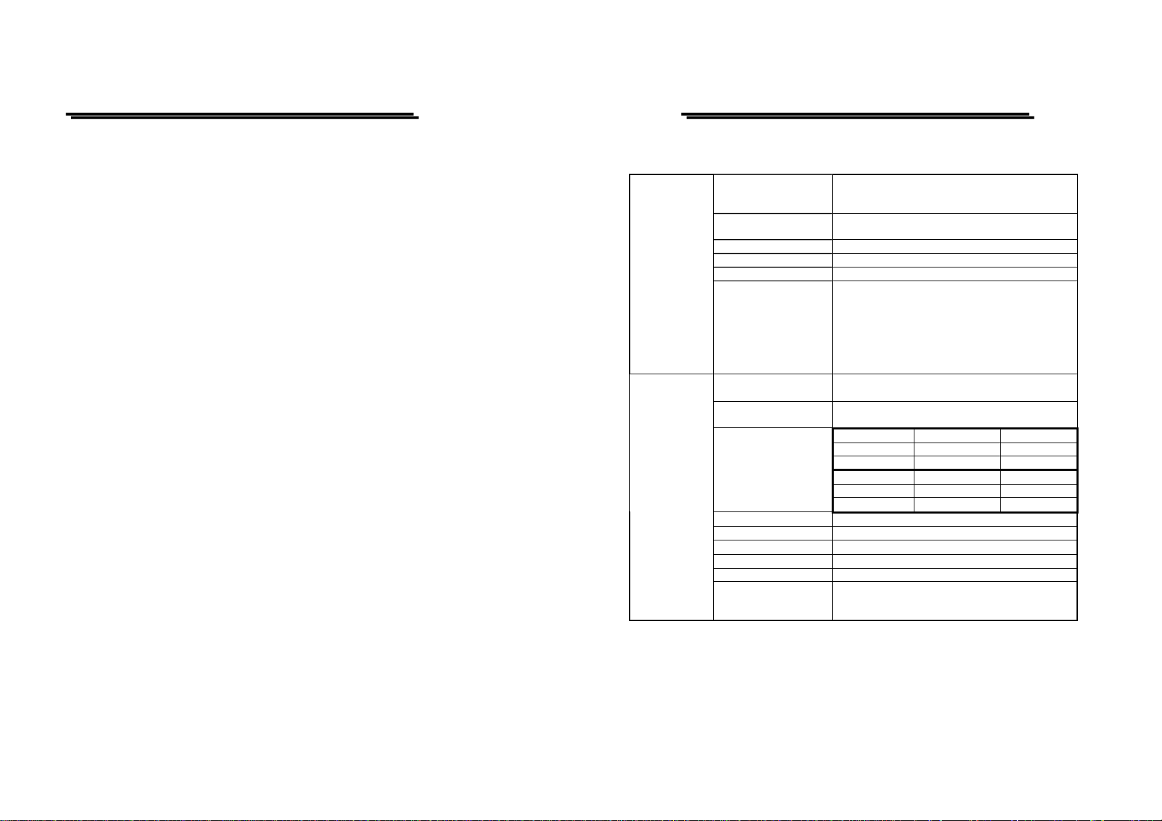
2.TECHNICAL SPECIFICATIONS
6-inch rectangular type with internal graticule;
0%, 10%, 90% and 100% markers.
8 x 10 DIV (1 DIV = 1 cm)
2kV (GRS-6032A)
Sensitivity: at least 5V
Polarity : positive going input decrease intensity
Usable frequency range: DC to 2MHz.
Max. input voltage: 30V (DC +AC peak) at 1kHz
or less.
Input Impedance: approx. 33kΩ(GRS-6052A)
1mV~2mV/DIV ± 5%, 5mV~20V/DIV ± 3%, 14
calibrated steps in 1-2-5 sequence.
Continuously variable to 1/2.5 approx. of panel
indicate value.
GRS-6052A Bandwidth(-3dB) Rise Time
5mV~20V/DIV DC~50MHz Approx. 7ns
1mV~2mV/DIV DC~7MHz Approx. 50ns
GRS-6032A Bandwidth(-3dB) Rise Time
5mV~20V/DIV DC~30MHz Approx. 11.7ns
1mV~2mV/DIV DC~7MHz Approx. 50ns
Approx. 1MΩ±2% // approx. 25pF
GRS-6052A: 8DIV at 40MHz, 6DIV at 50MHZ
GRS-6032A: 8DIV at 20MHz, 6DIV at 30MHz
CRT
VERTICAL
SYSTEM
Type
Accelerating Potential Approx. 10kV (GRS-6052A),
INTEN and FOCUS Front panel control.
Illumination Provided
Trace Rotation Provided.
Z-axis Input
(REAL TIME mode
only)
Sensitivity Accuracy
Vernier Vertical
Sensitivity
Bandwidth(-3dB) and
Rise Time
Maximum Input Voltage 400V (DC + AC peak) at 1kHz or less.
Input Coupling AC, DC, GND
Input Impedance
Vertical Modes CH1, CH2, DUAL(CHOP/ALT), ADD, CH2 INV.
CHOP Frequency Approx. 250kHz.
Dynamic Range
(REAL TIME mode
only)
47kΩ(GRS-6032A)
4
⎯ ⎯
5
⎯ ⎯
Page 6

GRS-6052A/6032A OSCILLOSCOPE
GRS-6052A/6032A OSCILLOSCOPE
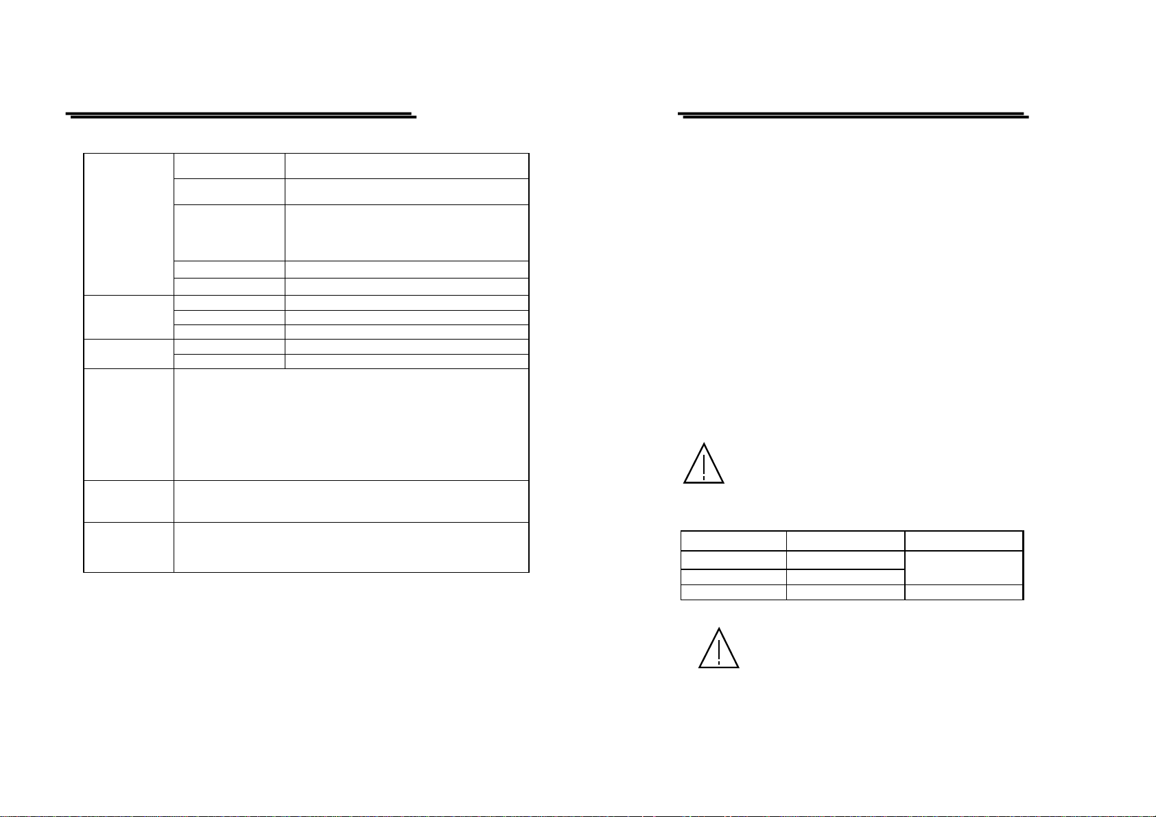
HORIZONTAL
SYSTEM
(REAL TIME
mode)
TRIGGER
SYSTEM
X-Y
OPERATION
(REAL TIME
mode)
USER MANUAL
Sweep Time
Accuracy ±3%, ±5% at ×5 and ×10 MAG, ±8% at ×20 MAG
Sweep Magnification ×5, ×10, ×20 MAG
Maximum Sw ee p Ti me
(at MAG)
ALT-MAG Function Available.
Trigger Modes AUTO, NORM, TV
Trigger Source VERT-MODE, CH1, CH2, LINE, EXT.
Trigger Coupling AC, HFR, LFR, TV-V(-), TV-H(-).
Trigger Slope “+” or “- ” polarity.
Trigger Sensitivity
External Trigger Input
Hold-off Time Variable (Real Time Mode only).
Input X-axis : CH1, Y-axis : CH2
Sensitivity 1mV/DIV~20V/DIV.
Bandwidth X-axis: DC~500kHz (-3 dB)
Phase Difference
0.2μs/DIV~0.5s/DIV, 20 steps selectable in 1-2-5
sequence, continuous variable control between steps
at least 1:2.5.
GRS-6052A:20ns/DIV (10ns/DIV uncalibrated)
GRS-6032A:50ns/DIV(10ns/DIV~40ns/DIV
uncalibrated.
GRS-6052A
20Hz~5MHz 0.5 DIV 2.0 DIV 200mV
5MHz~40MHz 1.5 DIV 3.0 DIV 800mV
40MHz~50MHz 2.0 DIV 3.5 DIV 1V
GRS-6032A
20Hz~2MHz 0.5 DIV 2.0 DIV 200mV
2MHz~20MHz 1.5 DIV 3.0 DIV 800mV
20MHz~30MHz 2.0 DIV 3.5 DIV 1V
TV sync pulse more than 1 DIV (CH1, CH2, VERTMODE) or 200mV (EXT).
Input impedance: Approx. 1MΩ//25pF(AC
coupling)
Max. input voltage: 400V (DC + AC peak) at 1kHz.
3°or less from DC to 50kHz
CH1,
CH2
CH1,
CH2
VERTMODE
VERTMODE
EXT
EXT
DIGITAL
STORAGE
FUNCTIONS
OUTPUT
SIGNAL
USER MANUAL
Acquisition Digitizer
Max. Sampling Rate
Acquisition Mode
Storage Bandwidth(3dB)
Dynamic Range
Memory Length
Acquisition Memory
Save REF Memory
Display Memory
Sweep Time
Sweep Magnification
Max. Sweep Time 10ns/DIV
MAG Interpolation Dots, Linear
ALT-MAG Function Available
Operation Mode
Smoothing Function Dot Joint ON/OFF selectable
Pre-trigger
X-Y Operation
Display Resolution
Waveform
SAVE/RECALL
CH1 Signal Output
Calibrator Output
8 bit ADC × 2
500MS/s for equivalent time sampling.
100MS/s for normal sampling.
Sample, Peak detect (>25ns), envelope, persistence,
average (2~256).
Single shot: DC to 25MHz.
Repetitive : DC to 50MHz (GRS-6052A)
DC to 30MHz (GRS-6032A)
±5DIV.
2k words/CH×2, 1k words/CH (equivalent)
1k words/CH×10 with back-up memory(REF 0~9)
1k words/CH×4 waveform (max.)
Equivalent: 0.2μs/DIV ~ 0.5μs/DIV
Normal: 1μs/DIV ~ 0.1s/DIV
Roll Mode: 0.2s/DIV ~ 100s/DIV
×5, ×10, ×20
Auto, Norm, Single, Single-roll, Roll, X-Y
Average (2 ~ 256), Run/Stop
0 ~ 10DIV in 0.02DIV steps (at 5μs/DIV ~
0.1s/DIV)
X-axis: CH1, Y-axis: CH2
Storage Bandwidth : DC~50MHz (GRS-6052A)
DC~20MHz (GRS-6032A)
H : 100 points/DIV
V : 25 points/DIV
X-Y: 25 × 25 points/DIV
10 sets (REF0 ~ REF9) with back-up memory.
Voltage : approx. 20mV/DIV (with 50Ω
terminal.)
Bandwidth: 50Hz to at least 5MHz.
Voltage : 0.5V±3%,
Frequency: approx. 1kHz, square wave.
6
⎯ ⎯
7
⎯ ⎯
Page 7
GRS-6052A/6032A OSCILLOSCOPE
GRS-6052A/6032A OSCILLOSCOPE
USER MANUAL
CH1/CH2 sensitivity, sweep time, trigger
condition, digital storage function.
10 sets
Cursor Measurement Function: ΔV, ΔT, 1/ΔT.
Cursor Resolution: 1/25 DIV.
Effective Cursor Range: Vertical:±3 DIV,
Horizontal: ±4 DIV
Adjustable
Remote control via a PC.
AC100V, 120V, 230V ±10% selectable.
275(W)×130(H)×370(D) mm.
CURSOR
READOUT &
CONTROL
INTERFACE
LINE POWER
REQUIREMENT
MECHANICAL
SPEC.
OPERATING
ENVIRONMENT
STORAGE
TEMPERATUR
E & HUMIDITY
ACCESSORIES
Panel Setting Display
Panel Setting Save &
Recall
Cursor Measurement
Text Readout Intensity
RS232 Interface
Voltage
Frequency 50Hz or 60Hz.
Power Consumption Approx. 70VA, 60W(max).
Dimensions
Weights 8.5 kg
Indoor use
Altitude up to 2000 m
Ambient temperature :
To satisfy specifications : 10℃ to 35℃ ( 50° F to 95°F )
Maximum operating ranges: 0℃ to 40℃( 32°F to 104°F )
Relative humidity: 85% RH(max.) non condensing
Installation Category : II
Pollution degree 2
-10° to 70℃, 70%RH(maximum)
Power cord….............……….. 1
Instruction manual…………… 1
Probe (×1/×10)…………..….... 2
Measurement category I is for measurements performed on circuits not
directly connected to MAINS.
Measurement category II is for measurements performed on circuits
directly connected to the low voltage installation.
Measurement category III is for measurements performed in the building
installation.
Measurement category IV is for measurements performed at the source of
the low-voltage installation.
USER MANUAL
3.PRECAUTIONS BEFORE OPERATION
3-1.Unpacking the Oscilloscope
The product has been fully inspected and tested before shipping from the
factory. Upon receiving the instrument, please unpack and inspect it to check if
there is any damages caused during transportation. If any sign of damage is
found, notify the bearer and/or the dealer immediately.
3-2.Checking the Line Voltage
The oscilloscope can be applied any kind of line voltage shown in the table
below. Before connecting the power plug to an AC line outlet, make sure the
voltage selector of the rear panel is set to the correct position corresponding to
the line voltage. It might be damaged the instrument if connected to the wrong
AC line voltage.
WARNING. To avoid electrical shock the power c ord protective
grounding conductor must be connected to ground.
When line voltages are changed, replace the required fuses shown as below:
Line voltage Range Fuse
100V 90-110V
120V 108-132V
230V 207-250V T 0.4A 250V
WARNING. To avoid personal injury, disconnect the power
cord before removing the fuse holder.
T 1A 250V
8
⎯ ⎯
9
⎯ ⎯
Page 8

GRS-6052A/6032A OSCILLOSCOPE
GRS-6052A/6032A OSCILLOSCOPE
USER MANUAL
3-3.Environment
The normal ambient temperature range of this instrument is from 0° to 40°C
(32° to 104°F). To operate the instrument over this specific temperature range
may cause damage to the circuits.
Do not use the instrument in a place where strong magnetic or electric field
exists as it may disturb the measurement.
3-4.Equipment Installation, and Operation
Ensure there is proper ventilation for the vents in the oscilloscope case. If the
equipment is used not according to the specification, the protection provided by
the equipment may be impaired.
3-5.CRT Intensity
To prevent permanent damage to the CRT phosphor, do not make the CRT trace
brighten excessively or leave the spot stay for an unreasonably long time.
3-6.Withstanding Voltages of Input Terminals
The withstanding voltages of the instrument input terminals and probe Input
terminals are shown in the following table. Do not apply voltages higher than
these limits.
Input terminal Maximum input voltage
CH1, CH2, inputs 400V (DC + AC peak)
EXT TRIG input 400V (DC + AC peak)
Probe inputs 600V (DC + AC peak)
Z AXIS input 30V (DC + AC peak)
USER MANUAL
4. PANEL INTRODUCTION
After the instrument is switched on, all the important settings are displayed in the
readout. The LED’s located on the front panel assist operation and indicate
additional information. Incorrect operation and the electrical end positions of
control knobs are indicat ed by a war ning be ep.
All of the pushbuttons, VOLTS/DIV control knobs, TIME/DIV control knobs are
electronically selected, and their functions and settings can therefore be stored
and remotely controlled as well. Some controls are only operated in the digital
storage mode or have a different function. Explanation pertaining to them are
indicated with the hint of “storage mode only”.
The front panel is subdivided into five sections:
z Display controls
z Vertical controls
z Horizontal controls
z Trigger controls
z Digital storage functions
CAUTION. To avoid damaging the instrument, do not apply
input voltages of the frequency over 1 kHz to the instrument.
10
⎯ ⎯
11
⎯ ⎯
Page 9
GRS-6052A/6032A OSCILLOSCOPE
GRS-6052A/6032A OSCILLOSCOPE
USER MANUAL
USER MANUAL
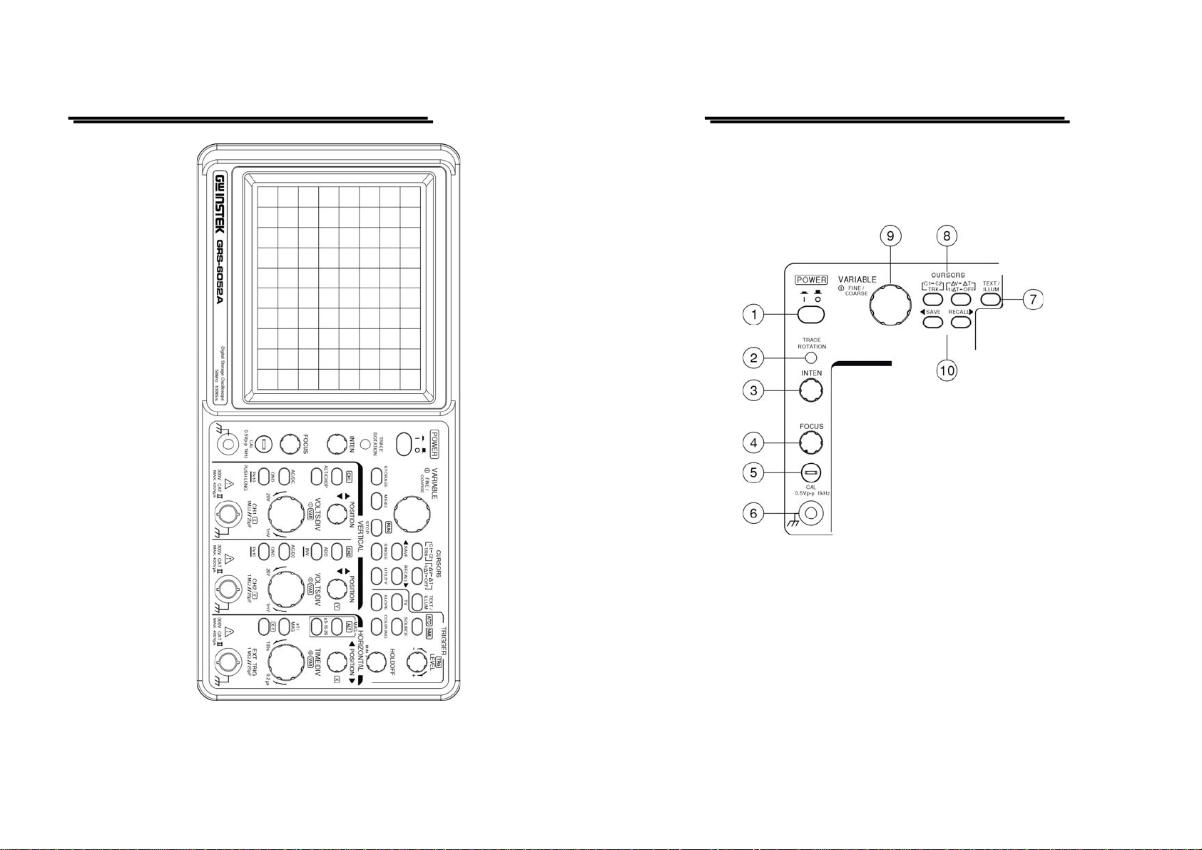
4-1.Front Panel
Display controls
The display controls adjust the on-screen appearance of the waveform and
provide a probe compensation signal source.
Front panel of GRS-6052A
12
⎯ ⎯
(1) POWER – Pushbutton
When switch on the oscilloscope to have all LEDs lighted and wait a few
seconds, the normal operation mode is present. Then the last settings become
activated and the LED indicates “ON” condition.
(2) TRACE ROTATION
The TRACE ROTATION is for aligning the horizontal trace in parallel with
graticule lines. This potentiometer can be adjusted with a small screwdriver.
13
⎯ ⎯
Page 10

GRS-6052A/6032A OSCILLOSCOPE
GRS-6052A/6032A OSCILLOSCOPE
USER MANUAL
(3) INTEN—Control knob (REAL TIME Mode only)
The control knob is used for adjusting the traces intensity in the real time
mode. Turning the knob clockwise to increase the intensity while turning it
counterclockwise to decrease the intensity.
(4) FOCUS
The control knob effects both the trace and the readout sharply.
(5) CAL
The terminal provides a reference signal of 0.5Vp-p at 1kHz for probe
adjustment.
(6) Ground Socket—Banana Socket galvanically connected to safety earth
This socket can be used a reference potential connection for DC and low
frequency signal measurement purpose.
(7) TEXT/ILLUM—Control knob with a double function.
The pushbutton is for selecting the text readout intensity function or scale
illumination function, and indicates the letter “TEXT” or “ILLUM” in the
readout. Press the pushbutton for the following sequences:
“TEXT” — “ILLUM” — “TEXT”
The TEXT/ILLUM function is associated the VARIABLE (9) control knob.
Turning the knob clockwise to increase the text intensity or scale
illumination, while turning the knob counterclockwise to decrease it.
Pressing the knob to switch the TEXT/ILLUM on or off.
In the STORAGE mode, the brightness of the waveform on the screen can be
controlled by the “TEXT”.
(8) CURSORS MEASUREMENT FUNCTION
There are two pushbutton and associated the VARIABLE (9) control knob.
When the pushbutton is pressed, the three measurement functions will be
selected in the sequence as follows:
△V—△T—1/△T—OFF
USER MANUAL
△V: Two horizontal cursors appear. The voltage between the two cursors is
calculated according to the setting of VOLTS/DIV, and displayed with
△V on the upper side of the CRT.
Single channel mode (CH1 or CH2):
The △V measuring result is automatically related to the deflection
coefficient of the active channel. The readout displays “△V1…” or
“△V2…”.
Dual channel mode:
The cursor lines must be set on the CH1 or CH2 signal. As the
deflection coefficients may be different, it will be required to select
between the deflection coefficient of CH1 and CH2.
ADD mode:
In ADD (addition) mode, normally two input signals are displayed as
one signal (sum or difference). As the result can only be determined if
both (calibrated) deflection coefficients are equal, the readout indicates
“ △ V…” without any additional channel information. Different
deflection coefficient settings or uncalibrated deflection coefficients
are indicated in the readout as “△V=…DIV”.
X-Y mode:
In the X-Y mode, the instrument is automatically set to △ V
measurement. The deflection coefficient selected for each channel may
be different, thus as in DUAL mode the △V cursor measurement
requires a channel selection. Under channel 1 (X signal) measuring
condition the cursor line s are disp lay ed a s verti cal l ines and the re adout
displays “△VX…”. Pressing the pushbutton, select channel 2 (Y
signal) measuring, then the cursor lines are displayed as horizontal
lines and the readout indicates “△VY…”.
△T: Two vertical cursors appear. The time between the two cursors is
calculated according to the setting of TIME/DIV, and displayed with
14
⎯ ⎯
15
⎯ ⎯
Page 11

GRS-6052A/6032A OSCILLOSCOPE
GRS-6052A/6032A OSCILLOSCOPE
USER MANUAL
△T on the upper side of the CRT.
1/△T: Two vertical cursors appear. The reciprocal of the time (frequency)
between the two cursors is calculated with 1/△T on the upper side of
the CRT.
C1—C2—TRK Pushbutton
The cursor 1, cursor 2 and tracking can be selected by this button. Pressi ng
the pushbutton to select the cursors in sequence as follows:
C1: Moves the cursor 1 on the CRT.
C2: Moves the cursor 2 on the CRT.
TRK: Simultaneously moves the cursor 1 and cursor 2 with the interval
between the two cursors unchanged.
(9) VARIABLE—
Set the cursor position, TEXT/ILLUM, etc. by turning or pressing the
VARIABLE knob.
In the cursor mode, pressing the VARIABLE control knob to select the
cursor position between FINE and COARSE adjustment. When select FINE
adjustment by turning the VARIABLE, the cursor lines will move slowly. If
select COARSE adjustment, he cursor will move fast.
In TEXT/ILLUM mode, this control knob can be used to set the text intensity
or illumination. Please refer to TEXT/ILL UM(7) for details.
USER MANUAL
(10). SAVE—RECALL
The instrument contains 10 non-vol atile memorie s, whic h can be us ed by t he
operator to save instrument setting and to recall them. It relates to all
controls which are electronically selected.
Press or pushbutton to select the memory location. The readout then
indicates the letter “M” followed by a cipher between 0 and 9. Each time t he
pushbutton is briefly pressed the memory location cipher increases until
the number 9 is reached. The pushbutton is similar but decreases the
memory location cipher until the number 0 is reached.
Pressing and holding SAVE for approx. 3 seconds to write the instrument
settings in the memory and indicate the associated readout information of
“ ”.
To recall a front panel setup, select a memory location as described above.
Recall the settings by pressing and holding the RECALL pushbutton for
approx. 3 seconds, the readout then indicates the associated readout
information of “ ”.
16
⎯ ⎯
17
⎯ ⎯
Page 12

GRS-6052A/6032A OSCILLOSCOPE
GRS-6052A/6032A OSCILLOSCOPE
USER MANUAL
Vertical controls
The vertical controls select the displayed signals and control the amplitude
characteristics.
(11) CH1—Pushbutton
(12) CH2—Pushbutton
Pressing briefly the CH1 (CH2) button to set the channel 1 (channe l 2) of
the instrument on, the deflection coefficient will be displayed in the readout
indicating the current conditions.
(13) CH1 POSITION—Control knob
The vertical trace position of channel 1 can be set with the control knob. When
X-Y operation in the Storage mode, C H1 POSITION control knob is use d for
the X deflection.
(14) CH2 POSITION—Control knob
The vertical trace position of channel 2 can be set with the control knob.
In X-Y operation, CH2 POSITION control knob is used for the Y
deflection.
USER MANUAL
(15) ALT/CHOP
In the REAL TIME mode, the pushbutton has two functions, which are
required and available only when both channels are active.
ALT—Displays in the readout, indicates alternate channel switching. After
each time base sweeps the instrument internally, switches over from channel
1 and channel 2 and vice ve rsa.
CHOP—Indicates chopper
The channel switching occurs constantly between channel 1 and channel 2
during each sweep.
In the STORAGE mode, ALT or CHOP mode is automatically selected by
TIME/DIV range. The ALT mode is established for the sweep range of
0.5ms/DIV or faster. The CHOP mode is established for the sweep range of
1ms/DIV or slower.
(16) ADD-INV—Pushbutton with double functions.
ADD– Displays the “+” symbol in the readout, indicates additional mode.
Whether the algebraic sum (addition) or the difference (subtraction) of both
input signals is displayed, depends on the phase relationship and the INV
setting. As a result, both signals are displayed as one signal. For correct
measurements, the deflection coefficients for both channels must be equal.
INV—Pressing and holding the pushbutton to set the channel 2 invert
function on or off. The inve rt on co ndition i s indicate d by the “ ” symbol
in the readout. The invert function causes the signal display of channel 2 to
be inverted by 18 0
o
.
(17) CH1 VOLTS/DIV
(18) CH2 VOLTS/DIV– Control knob for channel 1/channel 2 has double functions.
Turning the knob clockwise to increase the sensitivity in 1-2-5 sequence and
turning it in the opposite direction (CCW) to decrease. The available range is
from 1mV/DIV up to 20V/DIV. The knob is automatically switched inactive if
the related channel is switched off.
18
⎯ ⎯
19
⎯ ⎯
Page 13

GRS-6052A/6032A OSCILLOSCOPE
GRS-6052A/6032A OSCILLOSCOPE
USER MANUAL
The deflection coefficients and additional information regarding the active
channels are displayed in the readout.
VAR
Pressing the VOLTS/DIV control knob to select the VOLTS/DIV function
between attenuator and vernier (variable). The current setting is display ed by
the “>” symbol in the readout.
After switching on the VAR, turn the VOLTS/DIV control knob
counterclockwise to reduce the signal height, and the deflection coefficient
becomes uncalibrated.
(19) CH1 AC/DC
(20) CH2 AC/DC
Pressing the pushbutton briefly to switch over from AC (~ symbol) to DC (=
symbol) input coupling. The setting is displayed in the readout with the
deflection coefficien t.
(21) CH1 GND– P×10
(22) CH2 GND – P×10 –Pushbutton of two functions.
GND
Each time when the pushbutton is pressed briefly, the input of the vertical
amplifier is grounded. It is displayed in the readout as an earth (ground)
symbol “ ”.
P×10
Pressing and holding the pushbutton to select the indicated deflection
coefficient of the channel displayed in the readout between 1:1 and 10:1.
The probe factor of 10:1 is displayed in the readout with the probe symbol
“P× 10” in front of channel indication. When proceed cursor voltage
measurement, the probe factor will be automatically included. The sy mbol
must not be activated unless a 10:1 attenuator probes are used.
USER MANUAL
(23) CH1-X—Input BNC socket
This BNC socket is the signal input for channel 1. In X-Y mode, signals at
this input are used for the X deflection. The outer (ground) connection is
galvanically connected to the instrument ground and consequently to the
safety earth contact of the line/mains plug.
(24) CH2-Y—Input BNC socket
This BNC socket is the signal input for channel 2. In X-Y mode, signals at
this input are used for the Y deflection. The outer (ground) connection is
galvanically connected to the instrument ground and consequently to the
safety earth contact of the line/mains plug.
Horizontal controls:
The horizontal controls select the time base operation mode and adjust the
horizontal scale, position and magnification of the signal.
20
⎯ ⎯
21
⎯ ⎯
Page 14

GRS-6052A/6032A OSCILLOSCOPE
GRS-6052A/6032A OSCILLOSCOPE
USER MANUAL
(25) H POSITION (Real Time mode only)
The control knob enables a horizontal position shift of the signals. In
combination with MAG the function makes it possibl e to shift any part of t he
signal on the screen.
In X-Y mode, the control knob are used for the X deflection.
(26) TIME/DIV-VAR– Control knobs
Turning the knob clockwise to reduce the deflection coefficient in a 1-2-5
sequence and turning it in the opposite direction (CCW) to increase. The
time coefficient(s) will be displayed in the rea dout.
In the REAL TIME mode, the time deflection coefficients betwee n 0.5s/DIV
and 0.2μs/DIV can be chosen in 1-2-5 s equence, if the MAG funct ion is not
activated.
In the STORAGE mode, the sampling method is changed automatically by
the TIME/DIV range.
Equivalent sampling (E QU): 0.2μs/DIV to 0.5μs/DI V.
Only a repetitive signal can be stored.
Normal sampling (SMPL): 1μs/DIV to 0.1s/DIV.
Single shot and repetitive signal can be stored.
Roll mode: 0.2s/DIV to 100s/DIV.
For observing flickering low-speed signals.
VAR (Real Time mode only)
Pressing the pushbutton to select the TIME/DIV control knob function
between time base switch and vernier (variable). In the Real Time mode,
after switching on the VAR, the time deflection coefficient is still calibrated
until further adjustments are made. Turn the TIME/DIV control knob counter
clockwise to increase the time deflection coefficient (reduce the deflection
speed) and the deflection coefficient becomes uncalibrated. The current
setting is displayed by the “>” symbol in the readout.
USER MANUAL
(27) X-Y
Pressing the pushbutton when using the instrument as an X-Y oscilloscope.
The time deflection coefficient is replaced by the “X-Y” symbol in the
readout.
In this mode, the X (horizontal) signal is connected to the input of CH1; the
Y (vertical) signal is applied to the input of CH2 and has a deflection range
from less than 1mV to 20V/DIV at a reduced band-width of 500kHz (Real
Time mode).
In the Storage mode, the X-Y operation is same as the REAL TIME mode.
The storage waveform bandwidth of both X and Y signal are up to
50MHz/30MHz.
(28) ×1/MAG
Pressing the pushbutton the select the sweep time between ×1 (normal) and
MAG (magnify). If the MAG function, the signal display will be expanded
and consequently only a part of the signal curve is visible. The interesting
part of the signal can be made visible with the aid of the H POSITION
control in the REAL TIME mode.
(29) MAG FUNCTION
×5-×10-×20 MAG
When MAG has been done, the displayed waveform will be expanded to the
right and left with the center of the CRT. The magnification ratio can be
selected from among three stage of ×5-×10-×20 MAG by pressing this
pushbutton.
ALT MAG
Pressing the pushbutton, the primary sweep waveform along with the
magnified sweep waveform. The magnified can be displayed
simultaneously using the ALT-MAG function. The magnified sweep
waveform appears 3 divisions bel ow the pri mary sweep wa veform.
22
⎯ ⎯
23
⎯ ⎯
Page 15
GRS-6052A/6032A OSCILLOSCOPE
GRS-6052A/6032A OSCILLOSCOPE
USER MANUAL
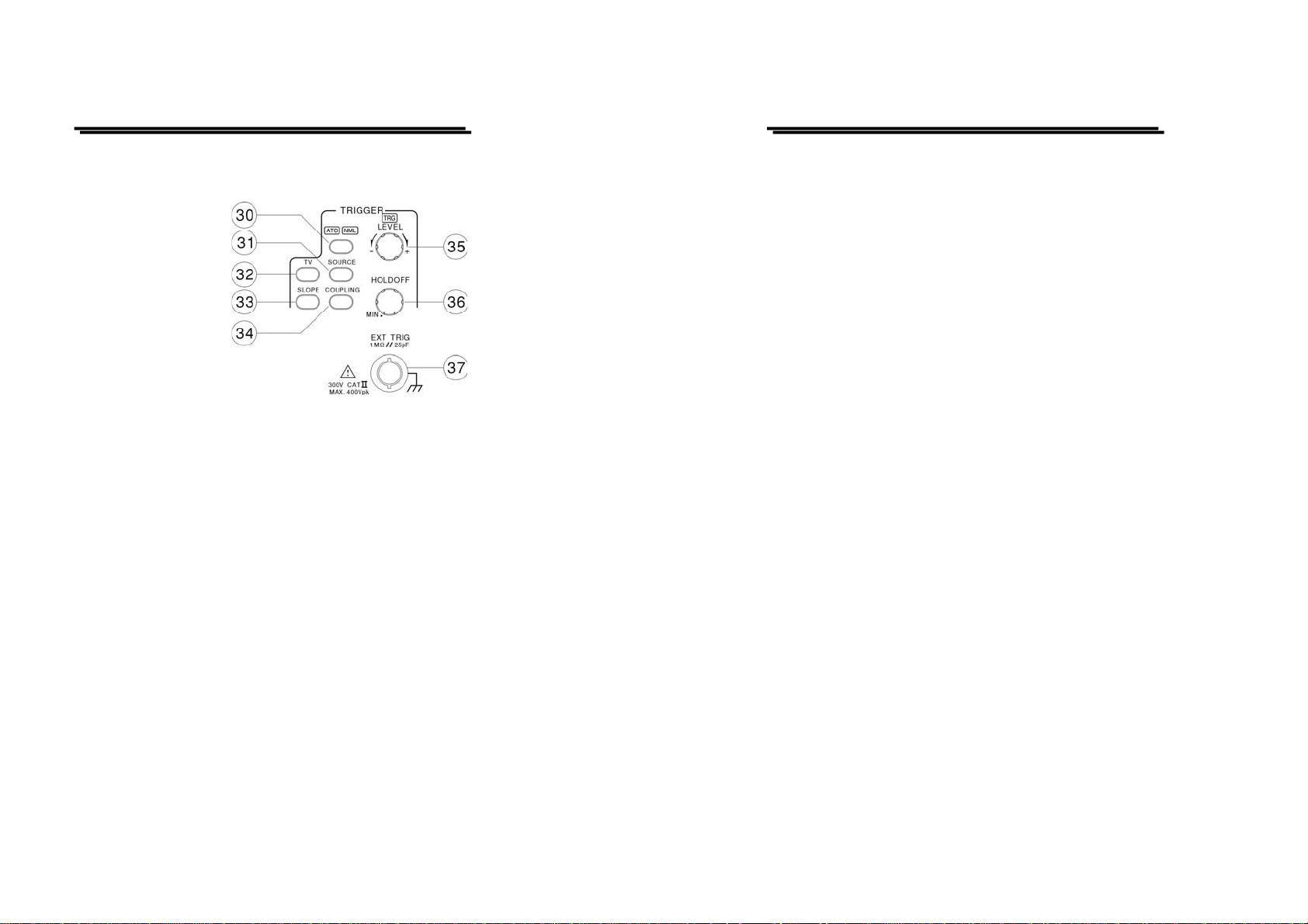
Trigger controls
The trigger controls determine the swee p start timing for both signals.
(30) ATO/NML – Pushbutton and indicator LEDs.
Pressing the pushbutton to select auto or normal trigger mode. The actual
setting is indicated by a LED.
Each time when the pushbutton is pressed the trigger mode change s in the
sequence:
ATO—NML—ATO
ATO (Auto)
Select the automatical mode, the sweep free-runs will display a baseline
trace when there is no trigger signal. The setting of triggering level changed
only when the TRIGGER LEVEL control is adjusted to a new level setting.
NML (Normal)
Select the normal mode, the input signal will trigger the sweep when the
TRIGGER LEVEL control is set within the peak-to-peak limits of an
adequate trigger signal. When the sweep is not triggered, no baseline trace
will be displayed.
Use this mode when effecting synchronization to a very low frequency
signal (25Hz or less).
USER MANUAL
(31) SOURCE—Pushbutton
Pressing the pushbutton to select the trigger signal source. The actual
setting is indicated by the readout (“SOURCE”, slope, coupling).
Each time when the pushbutton is pressed, the trigger source change in the
sequence:
VERT—CH1—CH2—LINE—EXT—VERT
VERT (Vertical Mode)
For observing two waveforms, the sync signal changes alternately
corresponding to the signals on CH1 and CH2 to trigger the signal.
CH1
The signal applied to the channel 1 input connector is the source of the
trigger signal.
CH2
The signal applied to the channel 2 input connector is the source of the
trigger signal.
LINE
The triggering signal is obtained from a sample of the AC power source
waveform. The trigger source is useful when the displayed waveform
frequency is time related to the AC power source freque ncy.
EXT
The external signal applied through the EXT input connector is used for the
external triggering source signal.
24
⎯ ⎯
25
⎯ ⎯
Page 16

GRS-6052A/6032A OSCILLOSCOPE
GRS-6052A/6032A OSCILLOSCOPE
USER MANUAL
(32) TV—Pushbutton for video sync signal selection
Separate the video sync signal from the composite waveform and direct it to
the triggering circuit. The horizontal or vertical sync signals are selected by
TV pushbutton. The current setting is displayed in the readout under item
(source, video polarity, “TVV or TVH”). Each time when the pushbutton is
pressed, the video sync signal is d isplayed in the sequences as follows:
TV-V—TV-H—OFF—TV-V
TV-V
Start the main trace at the beginning of a video signal field. The polarity
must match the composite sync polarity (i. e, “ ” fo r negative sync) to
obtain TV field triggering on the vertical sync pulse.
TV-H
Start the main trace at the beginning of a video signal line. The polarity
must match the composite sync polarity to obtain TV line triggering on the
horizontal sync pulse.
(33) SLOPE—Pushbutton for the triggering slope.
Briefly pressing the pushbutton to select the slope of the signal which is
used for triggering the time base generator. Each time when the pushbutton
is briefly pressed, the slope direction will switch from falling edge to rising
edge, and vice versa.
The current setting is displayed in the readout under item “source, SLOPE,
coupling”.
If in the TV trigger mode, it is synchronized only when the sync signal is
negative. A “ ” symbol is displayed in the readout.
USER MANUAL
(34) COUPLING—
Pressing the pushbutton to select the trigger coupling. The actual setting is
indicated by the readout (source, slope “COUPLING”).
Each time when the COUPLING pushbutton is pressed the trigger coupling
changes in the sequence:
AC—HFR—LFR—AC
AC
Attenuates trigger signal frequency components below 20Hz and blocks the
DC component of the signal.
AC coupling is useful for triggering on AC waveforms that have a large DC
offset.
HFR (High Frequency Reject)
Attenuates high-frequency triggering signal components above 50kHz. HFR
coupling is useful for providing a stable display of low-frequency
components of complex waveforms and eliminates high-frequency
interference from the trigger signal.
LFR (Low Frequency Reject)
Attenuates low-frequency triggering signal components below 30kHz and
blocks the DC component of the trigger signal.
LFR coupling is useful for producing stable triggering on the highfrequency components of complex waveforms and rejecting low-freq uency
interference or power supply hum from the trigger signal.
(35) TRIGGER LEVEL—Control knob with TRG LED
Turning the control knob causes a different trigger input setting (voltage),
and set to a suitable position for the starting of triggered sweep of the
waveform. When rotate clockwise the control knob, the trigger point moves
toward the positive peak of the trigger signal and rotate it counterclockwise
to move the trigger point toward the negative peak of the trigger signal.
26
⎯ ⎯
27
⎯ ⎯
Page 17

GRS-6052A/6032A OSCILLOSCOPE
GRS-6052A/6032A OSCILLOSCOPE
USER MANUAL
When the setting (voltage) value is out of the changing portion of the
observation waveform, the synchronization sweep stops.
TRG LED
The TRG LED is lit if the triggering conditions are met. Whether the LED
flashes or is lit constantly depends on the frequency of the trigger signal.
(36) HOLD-OFF—Control knob (REAL TIME mode only)
Used when the signal waveform is complex and stable triggering cannot be
attained with the TRIGGER LEVEL(35) knob alone, rotate this control knob
to adjust hold-off time(trigger inhibit period beyond sweep duration). When
control is rotated fully clockwise, the hold-off period is at MINimum
(normal). The hold-off period increases progressively with counterclockwise
rotation.
(37) TRIG EXT—This BNC socket is the external trigger signal input.
Pressing the TRIG. SOURCE (31) pushbutton until the information of “EXT,
slope, coupling” is shown up in the readout switches the input on.
The outer (ground) connection is galvanically connected to the instrument
ground and consequently to the safety earth contact of the line/mains plug.
The maximum input voltages of the input terminal are shown in the section
of 3-6. “Withstanding voltage of Input terminals”. Do not apply voltage
higher than the limit.
USER MANUAL
Storage Control
The Storage Control select the digital storage function.
(38) STORAGE/REAL TIME mode
Switch the REAL TIME mode to (digital) STORAGE mode by pressing the
button. In this case, all the switches from (39) to (42) are valid.
When the switch is pressed again in the STORAGE mode, the REAL TIME
mode is established again. In the STORAGE mode, the RUN LED blinks in
synchronism with sampling.
(39) MENU
Press the pushbutton to change the acquisition mode, the smoothing ON or
OFF, the interpolation method and the selection of SAVE/RECALL waveform
memory. Each pressing changes the setting mode and the present setting mode
is displayed at the top right on the CRT. The settings in each mode are
changed by the VARIABLE (9) control knob. Please refer to section 5-7 for
details.
(40) RUN/STOP—Pushbutton and indicator LED
Pressing this pushbutton to stop sampling, resulting in the hold state, and the
RUN LED is off. The current setting is indicated by the readout (“STOP”).
Further pressing the pushbutton to release hold state and start sampling states.
28
⎯ ⎯
29
⎯ ⎯
Page 18

GRS-6052A/6032A OSCILLOSCOPE
GRS-6052A/6032A OSCILLOSCOPE
USER MANUAL
(41) SINGLE
Pressing the pushbutton to set the SINGLE mode and the “SINGLE” message
will be indicated in the readout.
In this operation mode, a single signal acquisition process or sweep can be
started with a trigger. Providing the trigger circuit has been previously
activated with reset function, SINGLE is automatically switched to normal
triggering (NML LED lights up). Otherwise the trigger automatic would start
the signal acquisition processes without an input (trigger) signal.
Pressing the RUN/STOP pushbutton (reset function) again to resume a new
single event capture which then overwrites the previously recorded display.
(42) UTILITY
The instrument software contains several utility setting. Each time when the
UTILITY pushbutton is pressed, the readout displays the following message in
the sequence at the top right of the CRT:
RS232 baud rate
BEEP ON/OFF
FACTORY DEFAULT loading
RS232 Baud Rate
The setting of baud rate and data format on the instrument must be the same
as the one on the computer. The baud rate of the RS-232 interface can be
selected by turning the VARIABLE control knob according to the list as
follows:
300—900—1200—2400—4800—9600
Press the VARIABLE control knob to set RS-232 baud rate, the screen will
display “RM” in the upper left corner to show GRS-6052AA/6032 in the
Remote Control mode.
Note: When the baud rate is set, the front panel control will be locked.
Press UTILITY can unlock the front panel control and disable remote
control.
USER MANUAL
BEEP ON/OFF
When the “BEEP” is displayed, turning the VARIABLE control knob to set
the beep on or off. In the “OFF” condition, the acoustic signal s actuated by
the control limits are switched off.
FACTORY DEFAULT loading
When the “FACTORY DEFAULT” is displayed, pressing the VARIABLE
control knob to overwrite all panel setting memories (MEM0~MEM9), please
refer to the setting as follows:
REAL TIME mode : ON
VERTICAL : CH1: ON, CH2: ON
VOLTS/DIV: 0.5V
COUPLING: AC
HORIZONTAL : TIME/DIV: 100μs
TRIGGER : MODE: ATO
SOURCE: CH1
COUPLING: AC
SLOPE:
30
⎯ ⎯
31
⎯ ⎯
Page 19

GRS-6052A/6032A OSCILLOSCOPE
GRS-6052A/6032A OSCILLOSCOPE
USER MANUAL
4-2. Rear Panel
The rear panel provides input power and additional signal connections.
USER MANUAL
(45)CH1 Output—BNC socket
This output may be used to connect to a frequency counter or other
instrument.
(46)Z-Axis Inpu t—B NC sock et
Connect external signals to the Z-axis amplifier for intensity modulating the
CRT display. This terminal is DC-coupled. The intensity is lowered by a
positive signal, while it is increased by a negative signal.
(47)RS-232—Connector
Connect to other equipment with the RS-232 interface.
(43)Line voltage selector and input fuse holder—Select power source and
contain the primary power fuse
The fuse rating is shown in the section of 3-2 Checking the line voltage.
(44)AC power input connector
Connect the AC power cord to the power supply of instrument, the power
cord protective-ground connection is connected to the exposed metal part of
the instrument. The power cord must be connected to a proper grounded
source for electrical-shock protection.
32
⎯ ⎯
33
⎯ ⎯
Page 20

GRS-6052A/6032A OSCILLOSCOPE
GRS-6052A/6032A OSCILLOSCOPE
USER MANUAL
5. OPERATION METHOD
This section contains basic operation information and techniques that should be
considered before proceeding any measurement. As for the location and function
of instrument controls, connectors, and indicators, refer to the “Instruction of
Front Panel and Rear Panel” of this manual.
5-1.Readout Display
The CRT readout display indicates how to set up the instrument controls. No
physical marking shown on the rotating switches indicates the control setting. A
key to the location and type of readout information display are illustrated in
figure 5-1(a) and 5-1(b):
USER MANUAL
34
⎯ ⎯
Figure 5-1(a) REAL TIME mode Readout Layout
35
⎯ ⎯
Page 21

GRS-6052A/6032A OSCILLOSCOPE
GRS-6052A/6032A OSCILLOSCOPE
USER MANUAL
USER MANUAL
5-2.Connecting Input Signals
Grounding
The most reliable signal measurements are made when the oscilloscope and the
unit under test are connected by a common reference (ground lead) in addition
to the signal lead or probe. The ground lead of the probe provides the best
grounding method for signal interconnection and ensures the maximum amount
of signal-lead shielding in the probe cable. A separate ground lead (with a
banana plug) can also be connected from the unit under test to the oscilloscope
ground jack on the front panel.
Probes
A probe provides the most convenient way to connect an input signal to the
oscilloscope. The standard ×1/×10 probes supplied to the oscilloscope are
shielded against electromagnetic interference and have a high input impedance
for low circuit loading.
CAUTION. To get the best waveform precisely, keep
probe ground and signal leads as short as possible.
Figure 5-1(b) Storage Mode Readout Layout
36
⎯ ⎯
Misadjust probe compensation can cause measurement error. Check and adjust
probe compensation whenever a probe is moved to a different channel or
oscilloscope. As for the probe compensation adjustment procedure, refer to the
“Probe Compensation”.
Coaxial Cables
Signal input cable can greatly affect the acc uracy of a displayed waveform. To
maintain original frequency characteristics of the input signal, use only highquality, low-loss coaxial cables. Coaxial cables must be te rminated at both e nds
in their characteristic impedance to prevent signal reflections within the cable.
Use suitable impedance-matching devices.
37
⎯ ⎯
Page 22

GRS-6052A/6032A OSCILLOSCOPE
GRS-6052A/6032A OSCILLOSCOPE
USER MANUAL
5-3.Adjustments and checks
Trace Rotation Adjustment
Normally, when the trace is in parallel with the center horizontal graticule line,
there will be no need to adjust the TRACE ROTATION. If necessary, adjust the
TRACE ROTATION to make the baseline trace parallel to the center horizontal
graticule line by using a small straight-blade screwdriver or alignment tool.
Probe Compensation
To minimize the distortion of measured waveforms, check the compensation of
your probes before using them. The probe compensation should be checked
periodically whenever the probes are moved to different input channels.
1. Install the probes onto the oscilloscope (Press the BNC connector onto the
channel input and rotate the connector to lock it into place).
2. Set the probe slide switches to the ×10 position.
3. Briefly pressing the CH1/CH2 button to set the oscilloscope to channel 1 and
channel 2.
4. Pressing and holding the P×10 button to set the indicated deflection
coefficient of the channel displayed in the readout as a symbol “P10”.
5. Attach the probe tips to the CAL connection in the front of the oscilloscope.
6. Set the oscilloscope controls to display both channels:
VERTICAL: VOLTS/DIV 0.2V
COUPLING DC
ALT/CHOP CHOP
HORIZONTAL:
TIME/DIV 0.5ms
TRIGGER: MODE ATO
SOURCE VERT
COUPLING AC
SLOPE
USER MANUAL
either probe does not need to be adjusted, proceed the “Function Check”.
Figure 5-2 Typical Compensation Waveform
8. Adjust the probe by using a small insulated screwdriver. Slowly rotate the
adjustment control until the probe is properly compensated.
7. Observe the displayed waveform and compare them with the waveforms
shown in figure 5-2. If either probe needs to be adjusted, proceed the step 8. If
38
⎯ ⎯
39
⎯ ⎯
Page 23

GRS-6052A/6032A OSCILLOSCOPE
GRS-6052A/6032A OSCILLOSCOPE
USER MANUAL
5-4.Function Check
When you start to check the operation of your oscilloscope, proceed the
following instruction:
1. Install the ×10 probes onto CH1 and CH2 inputs.
2. Connect the probe tips to the CAL test point of the oscilloscope.
3. Set the oscilloscope controls to display both channels:
VERTICAL: VOLTS/DIV 0.2V
COUPLING DC
ALT/CHOP CHOP
HORIZONTAL:
TIME/DIV 0.5ms
TRIGGER: MODE ATO
SOURCE VERT
COUPLING AC
SLOPE
The figure 5-3 below illustrates a satisfactory display. The waveform should
be approximately 0. 5Vp-p at a frequency of 1kHz that confirms the ve rtical
and horizontal deflection function of the oscilloscope.
USER MANUAL
4. Set both CH1 and CH2 COUPLING to GND.
5. Use the CH1 and CH2 POSITION controls to align both traces on the center
graticule.
6. Open the CH2 INV by pressing and holding the pushbutton.
7. Set to the ADD mode by pressing the ADD pushbutton briefly.
8. Set both CH1 and CH2 COUPLING to DC.
9. The figure 5-4 below shows a satisfactory display. The display will show a
flat trace located on the center graticule that confirms the channel balance
and ADD offset function.
Figure 5-3 Function Check
40
⎯ ⎯
Figure 5-4 ADD mode
10. Turn off the ADD mode by pressing the ADD pushbutton briefly.
11. Turn off the CH2 INV by pressing and holding the pushbutton.
41
⎯ ⎯
Page 24

GRS-6052A/6032A OSCILLOSCOPE
GRS-6052A/6032A OSCILLOSCOPE
USER MANUAL
5-5.Basic Operation
Displaying CH1 or CH2
To display the signal from a signal channel, pressing briefly the CH1 or CH2
pushbutton to set the oscilloscope to channel 1 or channel 2.
Displaying CH1 and CH2
To display both signals at the same time, proceed the following steps:
1.Set the CH1 and CH2 on. The figure 5-5 below shows two synchronous
waveforms in the both modes.
2.Adjust the CH1 or CH2 POSITION control to position the two waveforms.
3.Set the ALT/CHOP button to CHOP mode if the waveforms are flickering.
USER MANUAL
Displaying the sum or difference of CH1 and CH2
To display the algebraic sum or difference of CH1 and CH2, proceed the
following steps:
1.Set the ADD button to ADD mode. The figure 5-6 below shows the sum of
the waveforms from figure 5-5.
2.Set the CH2 INV on by pressing and holding the button, if necessary, to
display the different waveform.
3. Pressing and holding one of the VOLTS/DIV control knob to set it to vernier
(variable). Then adjust one channel to the other in the event of gain
difference.
Figure 5-5 Both typical waveforms
42
⎯ ⎯
Figure 5-6 Typical ADD waveform
43
⎯ ⎯
Page 25

GRS-6052A/6032A OSCILLOSCOPE
GRS-6052A/6032A OSCILLOSCOPE
USER MANUAL
Comparing Frequency and phase (X-Y Operation)
To compare the frequency and phase between two signals by using the X-Y
mode. The X-Y waveform displays different amplitude, frequency, and phase.
The figure 5-7 shows a typical waveform made up of two signals that are of the
same frequency and amplitude, but approximate 45
o
out of phase.
To use the oscilloscope in the X-Y mode, proceed the following steps:
1. Connect the horizontal or X-axis signal to the CH1 input.
2. Connect the vertical or Y-axis signal to the CH2 input.
3. Set the X-Y button to X-Y operation (shown as Fig. 5-7 below).
Use the HORIZONTAL POSITION control to adjust the X-axis.
Note: When high frequency signals are displayed in the X-Y operation,
note the frequency bandwidths and phase difference between X and Y axis.
Refer to “2. SPECIFICATION” section for details.
USER MANUAL
Magnifying Waveform Events
Use the MAG pushbutton to view small portions of a waveform as which is too
far back from the starting point to view by using the TIME/DIV control. To use
the MAG button, proceed the follo wing step s:
1. Adjust the TIME/DIV to the fastest sweep that displays the event.
2.Rotate the HORIZONTAL POSITION control to move the event to display
on the center of screen.
3. Press the MAG button.
4.Select MAG ×5, MAG ×10, or MAG ×20 for MAG function.
When above procedures have been done, the displayed waveform will be
expanded 10 times to the right and left from the center of screen as center of
expansion.
Figure 5-7 Typical single X-Y display.
44
⎯ ⎯
Figure 5-8 Magnified Waveform
45
⎯ ⎯
Page 26

GRS-6052A/6032A OSCILLOSCOPE
GRS-6052A/6032A OSCILLOSCOPE
USER MANUAL
MAG-ALT Function
The input Signal is displayed by pressing MAG(magnify) and MAG-ALT(LED
light) buttons:
1. Set the wished portion of the waveform to the center of the screen for
magnification.
2. The magnified waveform spreads about 3 Divisions below the normal (×1)
waveform.
3. It is a normal function when the MAG-ALT button is pressed, the characters
will be vanished from the screen.
USER MANUAL
Operating Hold off time Control (REAL TIME mode only)
When the measured signal is a complex waveform with two or more repetition
frequencies (period), triggering with the LEVEL control alone may not be
sufficient to attain a stable waveform display. In such a case, the sweep can be
stable synchronized to the measured signal waveform by adjusting the Hold off
time of the sweep waveform.
Figure 5-10(a) shows several different waveforms which overlapped on the
screen, marking the signal observation unsuccessful when the hold off is set to
minimum.
Figure 5-10(b) shows the undesirable portion of the signal is held off. The same
waveforms are displayed on the screen without overlapping.
Figure 5-9(a) Mag.×1 Waveform Figure 5-9(b) Mag.×10 Waveform
46
⎯ ⎯
Figure 5-10(a) Hold-off Time Control
Figure 5-10(b) Hold-off Time Control
47
⎯ ⎯
Page 27

GRS-6052A/6032A OSCILLOSCOPE
GRS-6052A/6032A OSCILLOSCOPE
USER MANUAL
Observing the Synchronization of two Waveforms
When two signals of the CH1 and CH2 have the same frequencies with an
integral number, or a specific time difference, the SOURCE selects either CH1
or CH2 as a reference signal. Select CH1 signal from CH1 position and select
CH2 signal from CH2 position as a refe rence.
Set the SOURCE to VERT-MODE for observing the signal of different
frequencies. Switch the sync signal alternately to each channel, the waveform of
each channel will be trigge red stab ly.
When set the SOURCE to VERT-MODE and set the ALT/CHOP to ALT, the
input signals applied to CH1 and CH2 will become trigger source alternately
during sweep. Consequently, even the waveforms of different frequency of each
channel can be triggered stably.
Apply a sine wave to CH1 and a square wave to CH2, “A”s sho wn in Figure 511 are at the level possible for synchronization.
USER MANUAL
The VERT-MODE triggering is not possible when the signal is applied only to
one channel as shown in Figure 5-12 below:
Figure 5-12 Trig. Source on VERT. one channel
ALTERNATE TRIGGER
The Jittering wave as shown in Figure 5-13 may appear on the screen when a
gently-slopping sign al is displayed 10 cycles or less approximately by setting
VERT-MODE to SOURCE, and setting ALT/CHOP pushbutton to ALT. For
detailed and clear observati on of each signal, set VERTICAL mode to CH1 or
CH2.
Figure 5-11 Trig. Source on VERT
Apply AC coupling to CH2 in order to expand the synchronization range.
If the input signal of CH1 or CH2 becomes small, adjust VOLT/DIV control
knob to obtain sufficient amplitude.
The VERT-MODE triggering required 2.0 DIV which is larger than the
amplitude of CH1 or CH2.
48
⎯ ⎯
Figure 5-13 Alternate Trig.
49
⎯ ⎯
Page 28

GRS-6052A/6032A OSCILLOSCOPE
GRS-6052A/6032A OSCILLOSCOPE
USER MANUAL
Triggering of Video signal
In the work concerned with TV, complex signals and containing video signal,
blanking pedestal signal , and sy nchro nizing sig nal are o ften measur ed.
Press the TV pushbutton to set the TV position. The built-in active TV-Syncseparator provides the separation of frame or line sync pulses from the video signal.
To trigger the oscilloscope at the vertical (frame) rate, press the TV pushbutton to set
TV-V and TV-H triggering. The figure 5-14(a) shows vertical signal of TV-V and
Figure 5-14(b) shows horizontal signal of TV-H.
Figure 5-14(a) TV-V Figure 5-14(b) TV-H
The figure 5-15 shows the examples of TV polarity synchronization signals.
Note: This oscilloscope synchronizes with only ( ) synchronizing signal.
REFERENCE:
USER MANUAL
5-6. Digital Storage Functions
The operation procedure of the digital storage functions is described below.
Normal Sampling mode (SMPL)
1) Display the wa veform to be stored in the REAL TIME mode.
2) Press the STORAGE pushbutton switch and the RUN LED is on.
3) In this mode, a waveform is swept every trigger according to the setting
state of controls on the front panel, the waveform to be stored is displayed
on the CRT as it is. The slower the sweep rate, the longer the time is
required for the acquisition and display of the waveform. It takes
approximately 3 seconds until a waveform is acquired at the sweep range
of 0.1s/DIV. The trigger signal is generated thereafter. Therefore, when
the sweep rate is slow, the waveform is not displayed on the CRT
immediately after the controls on the front panel have been adjusted.
4) When the TIME/DIV control is from 1μs/DIV to 0.1s/DIV, both the
single and the repetitive waveforms can be stored.
Equivalent Sampling Mode (EQU)
When the TIME/DIV control knob is set to 0.2μs/DIV to 0.5μs/DIV ( 2 steps ),
only the repetitive waveform can be stored in the equivalent sampling mode.
The first (left end) rising and falling edges of the traces may not be displayed
in the repeat mode range. In this case, measure the rising or falling edge on the
second or later cycles of the waveform.
It takes 5 seconds or more to store the inpu t signal of 1kH z or lower. When t he
low frequency signal is stored, noise can be mixed. It is recommended to use a
sine wave of 1MHz or higher or a square wave with the rise time which is
faster than 0.3μs.
Figure 5-15 TV Signal
50
⎯ ⎯
51
⎯ ⎯
Page 29

GRS-6052A/6032A OSCILLOSCOPE
GRS-6052A/6032A OSCILLOSCOPE
USER MANUAL
Figure 5-16
ROLL mode
The displayed waveform is rolled from right to left (0.2s/DIV to 100s/DIV).
The right end of each trace is the updating po int of a new data. The Roll mode
facilitates the measure ment of a sign al of appro ximately 100H z or lower . Press
the STOP switch to stop the ROLL mode and hold the final waveform on the
CRT.
USER MANUAL
Figure 5-17
NOTE:
Aliasing:
While measuring the signal in such STORAGE mode as SMPL, AVG, etc., the
aliasing can be occurred by inputting a signal of more than half of the
frequency with respect to th e sample clock frequency at the sweeping range is
added.
When the aliasing is occurred, the waveform of the input signal frequency
minus the sample clock frequency will be displayed. It is possible that this
display is judged a current waveform. If the aliasing is suspected, select the
REAL TIME mode and check if the display is the same as that in the actual
operation mode.
52
⎯ ⎯
53
⎯ ⎯
Page 30

GRS-6052A/6032A OSCILLOSCOPE
GRS-6052A/6032A OSCILLOSCOPE
USER MANUAL
PRE-TRIGGER
Measure the waveform before the trigger point.
Although a conventional oscilloscope displays the trigger point only at the left
end of the screen since the sweep starts at the trigger point of the signal, the
instrument can display the trigger point anywhere on the screen in 0.1DIV
steps, using the PRE-TRIGGER function in the STORAGE mode, so that it is
possible to measure the waveform before the trigger point precisely.
1) When the MENU and CURSOR functions are off, the position of the
trigger point is displayed.
2) The position of the trigger point is set by the VARIABLE control knob.
3) For example, in the case of 4.0DIV setting, the signal before the rising
edge of the wave form (the triggered point) can be observed as shown in
Figure 5-18 below.
USER MANUAL
MENU
The acquisition mode, the on-off settings of the waveform smoothing, the
interpolation method in the horizontal ma gnification mode, the save and recall
memory can be selected by the MENU pushbutton.
Each time when the MENU pushbutton is pressed, the readout displays at the
top right of the CRT in the sequence as follows:
MENU 1: “acquisition mode"
MENU 2: SMOOTH
MENU 3: INTRPL
MENU 4: SAVE
MENU 5: RECALL
OFF
1) Select acquisition mode
When the “MENU 1: acquisition” mode is displayed at the top right of the
CRT, the selection of acquisition mode can be set.
MENU1 : PEAK
Acquisition mode Setting marker by VARIABLE
SMPL: Normal Sampling
PEAK: Peak Detect
PERSIST: Persistence Display
ENVELOPE: Envelope Display
AVERAGE: 2~256 times
Figure 5-18
54
⎯ ⎯
The Acquisition mode is selected by the VARIABLE control knob.
Acquisition is the process of sampling for the analog input signal,
converting it into digital format afterward and assembling it into a
waveform record finally .
55
⎯ ⎯
Page 31

GRS-6052A/6032A OSCILLOSCOPE
GRS-6052A/6032A OSCILLOSCOPE
USER MANUAL
SMPL(0.1s~1μs/div)
In normal sampling mode, the instrument generates a record point by
saving the first sample during each acquisition interval.
PEAK(100s~5μs/div at one channel, 0.5ms~5μs/div at two channels)
The peak detect mode stores the minimum and maximum values (pairs)
for each time bucket. This mode is capable of detecting glitches of 25ns or
more regardless of the sweep rate.
PERSIST(0.1s ~0.2μs/div)
The persistence mode displays the minimum and maximum values
mutually in the normal sampling and initialization by changing the
TIME/DIV control knob. This mode can acquire and display a waveform
record that shows the total variation over entire acquisition.
ENVELOP (0.1s ~5μs/div at one channel, 0.5ms~5μs/div at two
channels)
The Envelope mode activates both peak detect and persistence mode. This
mode monitors signal variations over time. You can measure interference
signals, jitter, amplitude modulated signals and more.
AVERAGE (0.1s ~0.2μs/div)
In the Average mode, pressing the VARIABLE control knob to set the
number of average, turning the knob clockwise to change the number
from 2 to 4-8-16-32-64-128-256 and turning the knob counter-clockwise
to change the number in the reverse order, the average waveform is
displayed after the data of the set sweep number has been acquired.
When the number of average is 16, the data is acquired 16 times (the RUN
LED blinks 16 times). Thus, the non-repetitive signal affected by
asynchronous noise can be picked up. The average operation is
performed by setting the number of average. In the ROLL mode, the
average operation is not performed.
USER MANUAL
2) Smoothing selection mode
When the “MENU 1: SMOOTH” is displayed at the top right of the CRT,
the smoothing is made on and off.
MENU1 : SMOOTH OFF
OFF: No Smoothing Setting marker by VARIABLE
ON: Smoothing
In case of OFF, the storage waveform is displayed by dots, while changing
to ON, the dots are connected smoothly as result of a smooth waveform
display.
When the sampling frequency is low with respect to the input signal
frequency (when the signal of more than 5 cycles per division is
connected), the amplitude to be display may be small. In this case, set the
smoothing mode to OFF to display the waveform of the similar amplitude
with the input signal. The setting can be done by the VARIABLE control
knob.
3) Interpolation Method Selection mode
When the “MENU 3: INTRPL” is displayed at the top right of the CRT,
THE interpolation Method can be selected.
MENU 3 : I NTRP L DOT
DOT: No interpolation Setting marker by VARIABLE
LINEAR: Linear interpolation
The mode selection is made by the VARIABLE control knob. The
interpolation method is how to interpolate the magnified data while
magnifying the display waveform in the horizontal direction (except for
the SAVE/RECALL reference waveform). In the case of DOT, the
56
⎯ ⎯
57
⎯ ⎯
Page 32

GRS-6052A/6032A OSCILLOSCOPE
GRS-6052A/6032A OSCILLOSCOPE
USER MANUAL
waveform is magnified as is in the horizontal direction.
In the case of LINEAR, the data is interpolated linearly, and the waveform
is displayed smoother than at DOT. This is effective for a square wave or
sine wave.
4) Save reference memory setting mode
When the “MENU 4: SAVE” is displayed at the top right of the CRT, the
save reference memory can be selected. Save completed.
MENU4 : SAVE CH1
Source Waveform: Setting marker by VARIABLE
CH1: only CH1
CH2: only CH2 REF0: Save to REF0 memory
ADD: only CH1+CH2 ∣
SUB: only CH1-CH2 REF0: Save to REF9 memory
The source waveform is automatically switched by ve rtical mode. When
both CH1 and CH2 are active, pressing the VARIABLE control knob to
select the source waveform between C H1 and CH2.
Turning The VARIABLE control knob clockwise to change the number of
reference memory from REF0 to REF9 and turning the knob
counterclockwise to change the number in the reverse order.
When the source waveform and the number of reference memory are
established, pressing the SAVE pushbutton to write the source waveform
in the memory and indicate the associated readout information of “ ”.
R EF0
USER MANUAL
5) RECALL reference
When the “MENU5:RECALL” is displayed at the top right of the CRT,
the recall reference memory can be selected. Recall Completed
MENU4 : SAVE CH1
Setting marker by VARIABLE
REF0: Recall REF0 memory
∣
REF0: Recall REF9 memory
Turning the VARIABLE control knob clockwise to change the number of
reference memory from REF0 to REF9 while turning the knob
counterclockwise to change the number in the reverse order.
R EF0
+Recall the waveform on the CRT by pressing the RECALL pushbutton,
the readout then indicates the associated readout information of “ ”.
When this pushbutton is pressed again, the displayed waveform will be
removed.
58
⎯ ⎯
59
⎯ ⎯
Page 33

GRS-6052A/6032A OSCILLOSCOPE
GRS-6052A/6032A OSCILLOSCOPE
USER MANUAL
5-7.Measurement Application
The oscilloscope has a cursor measurement system for making accurate, directreadout voltage, time and frequency measurements. The measurements
described in this section are examples of typical applications using this
measurement system. After becoming familiar with the c ontrols, indicators, a nd
capabilities of the instrument, you ca n develop convenie nt methods to make the
special measurement for your own applications.
Proceed a measurement by using the cursor according to the following steps:
1. Press the [△V—△T, 1/△T—OFF] pushbuttons to turn on the cursor and
measurement readout.
2. Press the pushbutton to select the seven measurement function in the
sequence as below:
△ V —△T —1/△T—OF F
3. Press the [C1—C2 TRK] pushbutton to select C1 cursor, C2 cursor and
tracking cursor.
4. Rotate the VARIABLE control knob to position selected cursor. Press one of
the VARIABLE control knob to select FINE or COARSE cursor move speed.
5. Read the measurement value on the screen. Typical measurement readouts
and applications are shown in Figure 5-16. The measurement values are
automatically controlled by the VOLTS/DIV and TIME/DIV control settings.
USER MANUAL
Figure 5-19: Cursor Measurement
(a).Typical △V (Voltage difference) for
AC voltage.
When both CH1 and CH2 are turned on,
the measurement value of CH1(△V1).
(b).Typical △ T(Time difference) cursor
measurement for rise time.
Proceed rise-time or fall-time
measurement requiring some additional
signal scaling by using the graticule
rise-time measurement aids. Number 0%,
10, 90 and 100 are etched near the left
vertical graticule line. Use the following
steps as a guideline to in making risetime measurement:
(c).Typical 1/ △ T cursor function for
frequency measurement.
When the two cursors are superimposed
at two edge points of the one period
waveform by the [C1—C2 TRK] and
VARIABLE controls, the measurement
value is displayed in frequency units on the upper side of the screen.
NOTE. When the VOLTS/DIV or the TIME/DIV controls are in uncalibrated
setting, the △ V and △ T measurement values will be displayed with
divisions.
When the vertical mode is set to the ADD mode, and the CH1 and CH2
VOLTS/DIV controls are set to different scales, the △V measurement values
will be displayed with divisions.
60
⎯ ⎯
61
⎯ ⎯
Page 34

GRS-6052A/6032A OSCILLOSCOPE
GRS-6052A/6032A OSCILLOSCOPE
USER MANUAL
5-8 RS-232 Interface –Remote Control
5-8-1. RS-232 Configuration
The GRS-6052A/6032A contains a DB 9-pin, male RS-232 connector for serial
communication with a computer or terminal. The GRS-6052A/6032A RS-232
interface is configured as an RS-232 “Data Terminal Equipment” so that data is sent
from pin 3 and rece ived on pin 2. For r emote contr ols, th e RS-232 inte r face has to b e
connected with a computer or terminal.
Pin Assignm ent s
The pin assignments for RS-232 interface of GRS-6052A/6032A are listed below.
1. No connection
2. Receive Data (RxD) (input)
3. Transmit Data (TxD) (output)
4. No connection
5. Signal Ground (GND)
6. No connection
7. No connection
8. No connection
9. No connection
Figure 5-20. Pin assignments of the RS232 connector on the rear panel for DB-9-D
USER MANUAL
DB9 to DB9 Wiring
The wiring configuration is used for computer with DB9 connectors that configured
as Data Terminal Equipment.
GRS-6052A/6032A
(DB9, DTE)
Pin2
Pin3
Computer
(DB9, DTE)
Pin2
Pin3
Pin5Pin5
Figure 5-21. DB9 to DB9 wiring
When the GRS-6052A/6032A is set up with a RS232 interface, please check the
following points:
z Do not connect the output line of one DTE device to the output line of the other.
z Many devices require a constant high signal on one or more input pins.
z Ensure that the signal ground of the equipment is connected to the signal
ground of the external device.
z Ensure that the chassis ground of the equipment is connected to the chassis
ground of the external device.
z Do not use more than 15m of cable to connect devices to a PC.
z Ensure the same configurations are used on the device as the one used on PC
terminal.
z Ensure the connector for the both side of cable and the internal connected line
are met the demand of the instrument.
62
⎯ ⎯
63
⎯ ⎯
Page 35

GRS-6052A/6032A OSCILLOSCOPE
GRS-6052A/6032A OSCILLOSCOPE
USER MANUAL
Communication Mode
The same baud rate and data format must be set to the instrument and the computer.
The baud rate of the RS-232 interface can be set as listed in the following table.
300 Baud 900 Baud 1200 Baud
2400 Baud 4800 Baud 9600 Baud
The data transmission format is N-8-1 (no parity bit, 8 data bits, 1 stop bits).
Computer’s Connection
A personal computer with a COM port is the essential facility in order to operate the
instruction via RS232 interface.
The connections between GRS-6052A/6032A and computer are as follows:
1) Connect one end of a RS232 cable to the computer.
2) Connect the other end of the cable to the RS232 port on the GRS-
6052A/6032A.
3) Turn on the GRS-6052A/6032A.
4) Turn on the computer.
USER MANUAL
The RS232 connection testin g
If you want to test whether the RS232 connection is working or not, you can send a
command from computer. For instance, using a terminal program send the query
command (uppercase)
*IDN?
should return the Manufacturer, model number, serial number and firmware version
in the following format:
GW,GRS60X2A,V.1.10
If you do not receive a proper response from the GRS-60X2A, please check if the
power is on, the RS232 configurations are the same on both sides, and all cable
connections are active.
64
⎯ ⎯
65
⎯ ⎯
Page 36

GRS-6052A/6032A OSCILLOSCOPE
GRS-6052A/6032A OSCILLOSCOPE
USER MANUAL
5-8.2. RS-232 Remote Control
Command Synta x
All commands syntax is ASCII format. If you want to transfer any of the
instructions to an instrument, there are five basic elements must be included.
z Command he ader:
Distinguish commands
z Command type:
Equal mark (=): Sets instrument state
Question mark (?): Queries instrument state
z Parameter (if required)
Instrument states value
z Target (if required)
Some commands need to be assigned specific channel
z Message terminator or separator
USER MANUAL
Here are some valid examples remote control commands (not including message
terminator):
V 1 = 0 1 0 A
H 4 = 0 0 1
M2?
* I D N ?
The following example includes the header, ty pe, value for the parame ter, and target
(This command will set channel 1 verti cal gai n at 20mV /DIV):
V 1 = 0 1 0 A
Command Header: V1
Command Type: =
Parameters: 010
Target: A
Command
Header
Command
Type
Parameter Target
Message
terminator
or separator
2 bytes 1 byte 3 bytes 1 byte 1 byte
66
⎯ ⎯
Note: The GRS-60X2A is sensitive to the case of command characters. All of the
commands are uppercase.
67
⎯ ⎯
Page 37

GRS-6052A/6032A OSCILLOSCOPE
GRS-6052A/6032A OSCILLOSCOPE
USER MANUAL
Message Terminator and Message Separator
As there is no signal of end message on RS232 bus, therefore use LF (Line Feed, 0×
0A) as message terminator. When a series of commands are sent to the instrument, it
must add a LF to be a judgment for message terminator. As for query command, the
return message of the instrument is also added a LF for PC to judge message
terminator.
A semicolon separates one command from another when the commands appear on
the same line.
Return Data Format
If instrument received question mark (?) at the third byte (command type) of
the command, it will answers 3 bytes value in ASCI I format and 1 byte
message terminator of LF (0x0A).
The following example ask the Time base scale, and instrument will return
010 (.1s/DIV):
Example: H 1 ? (ASCII)
Return: 0 1 0 (3 bytes, ASCII format)
If instrument receive s WA?-WD?. It will return 1000 bytes channel 1, channel 2 or
2 recalled waveforms data in Binary format and 1 byte message terminator.
Example: W A ? (ASCII)
Return:
1000 bytes waveform data
Message
terminator
0x01 0x05 …… 0x09 0x0A
USER MANUAL
If instrument receives W0?-W9?. It will return 3 bytes waveform information, 1000
bytes waveforms data in Binary format and 1 byte message terminator.
Example: W 5 ? (ASCII)
Return:
VAR
Vertical
scale
Horizontal
scale
1000 byte waveform
data
Message
terminator
0x01 0x05 0x10 0x01, 0x05,……,0x09 0x0A
VAR=0: Vertical VAR function disable.
VAR=1: Vertical VAR function enable.
Vertical scale: 1-14(20V/DIV – 1mV/DIV).
Horizontal scale: 10-27(.1s/DIV - .2us/DIV).
Combining Commands
You can use a semicolon (;) to combine commands and queries. The GRS-60X2A
executes coherent commands in the order it receives them. When you coherent
queries, the GRS-60X2A combine the responses into a single response message. For
example, if the channel 1 display is ON (001) and horizontal time base scale equals
to 1ms/DIV (016), the query commands (must add 1 byte me ssage terminator)
V 3 ? A ; H 1 ?
Instrument will return the message
0 0 1 0 1 6
68
⎯ ⎯
69
⎯ ⎯
Page 38

GRS-6052A/6032A OSCILLOSCOPE
GRS-6052A/6032A OSCILLOSCOPE
USER MANUAL
Buffer Size
The command receive buffer of instrument is 128 bytes. The return message buffer
of instrument is 1024 bytes.
If your combining commands size is larger than 128 bytes, commands will be lost.
If you query the waveform data (WA? or WB?), the instrument will return 1000
bytes waveform data. Do not use any quer y commands during the data transmission.
USER MANUAL
Command List
Note: Every command must add 1 byte message terminator of LF (0x0A).
Function Transmission Format
*IDN? *IDN?
*CLR *CLR
*ULK *ULK
*RST *RST
V1=<Parameters (3bytes)><Target (1byte)>
Vertical Scale
V1? <Target (1byte)>
V2=<Parameters (3bytes)><Target (1byte)>
Input Coupling
V2? <Target (1byte)>
V3=<Parameters (3bytes)><Target (1byte)>
Display
V3? <Target (1byte)>
70
⎯ ⎯
Probe
V-VAR
Invert
ADD
V4=<Parameters (3bytes)><Target (1byte)>
V4? <Target (1byte)>
V5=<Parameters (3bytes)><Target (1byte)>
V5? <Target (1byte)>
V6=<Parameters (3bytes)>
V6?
V7=<Parameters (3bytes)>
V7?
71
⎯ ⎯
Page 39

GRS-6052A/6032A OSCILLOSCOPE
GRS-6052A/6032A OSCILLOSCOPE
ALT/CHOP
Horizontal Scale
Pre-trigger Position
H-VAR
XY Mode
Sweep Magnification
MAG-ALT
Trigger Mode
Trigger Source
Trigger Couple
USER MANUAL
V8=<Parameters (3bytes)>
V8?
H1=<Parameters (3bytes)>
H1?
H2=<Parameters (3bytes)><Target (1byte)>
H2?
H3=<Parameters (3bytes)>
H3?
H4=<Parameters (3bytes)>
H4?
H5=<Parameters (3bytes)>
H5?
H6=<Parameters (3bytes)>
H6?
T1=<Parameters (3bytes)>
T1?
T2=<Parameters (3bytes)>
T2?
T3=<Parameters (3bytes)>
T3?
Trigger Slope
Dump Waveform
Smooth
Average
MAG Interpolation
Acquisition Mode
Real-time/
Storage
RUN/STOP
Text Intensity
Illumine Intensity
USER MANUAL
T5=<Parameters (3bytes)>
T5?
WA? WB? WC? WD?
W [0-9] ?
M1=<Parameters (3bytes)>
M1?
M2=<Parameters (3bytes)>
M2?
M3=<Parameters (3bytes)>
M3?
M4=<Parameters (3bytes)>
M4?
O1=<Parameters (3bytes)>
O1?
O2=<Parameters (3bytes)>
O2?
O3=<Parameters (3bytes)>
O3?
O3=<Parameters (3bytes)>
O3?
TV Trigger
T4=<Parameters (3bytes)>
T4?
72
⎯ ⎯
73
⎯ ⎯
Page 40

GRS-6052A/6032A OSCILLOSCOPE
GRS-6052A/6032A OSCILLOSCOPE
USER MANUAL
Details of Command Reference
Each command in this chapter will give a brief description. The examples of each
command will be provided and what query form might return.
Note: Every command must add 1 byte message terminator of LF (0x0A).
Common Commands
*IDN?
* IDN?
Queries the unique identification code of instrument
Return: GW,GRS60X2A,V.1.10
*CLR
USER MANUAL
*RST
* RST
Load factory default setti ng into inst rume nt
Vertical Controls Commands
Vertical Scale
V 1 = Parameters (3Bytes) Target
V1?Target
Sets or queries the vertical gain of the specific channel.
Syntax
V1=010A
* CLR
Clear the output buffer data of instrument
*ULK
* ULK
Unlock front panel control
74
⎯ ⎯
V1?B
Arguments
Parameters:
001→20V/DIV 002→10V/DIV 003→5V/DIV 004→2V/DIV
005→1V/DIV 006→.5V/DIV 007→.2V/DIV 008→.1V/DIV
009→50mV/DIV 010→20mV/DIV 011→10mV/DIV 012→5mV/DIV
013→2V/DIV 014→1mV/DIV
Target:
A→Channel 1 B→Cha nnel 2
75
⎯ ⎯
Page 41

GRS-6052A/6032A OSCILLOSCOPE
GRS-6052A/6032A OSCILLOSCOPE
USER MANUAL
Input Coupling
V 2 = Parameters (3Bytes) Target
V2?Target
Sets or queries the input coupling states.
Syntax
V2=001B
V2?A
Arguments
Parameters:
000→Place scope in DC coupling state
001→Place scope in AC coupling state
USER MANUAL
Sets or queries the channel’s display.
Syntax
V3=001A
V3?B
Arguments
Parameters:
000→Disable channel display 001→Enable channel display
Target:
A→Channel 1 B→Cha nnel 2
Probe
V 4 = Parameters (3Bytes) Target
V4?Target
002→Place scope in grounding state
Target:
A→Channel 1 B→Cha nnel 2
Display
V 3 = Parameters (3Bytes) Target
V3?Target
76
⎯ ⎯
Sets or queries the probe attenuation factor.
Syntax
V4=001B
V4?A
Arguments
Parameters:
000→1X 001→10X
77
⎯ ⎯
Page 42

GRS-6052A/6032A OSCILLOSCOPE
GRS-6052A/6032A OSCILLOSCOPE
USER MANUAL
Target:
A→Channel 1 B→Cha nnel 2
V-VAR
V 5 = Parameters (3Bytes) Target
V5?Target
Sets or queries the vertical VAR function of the specified channel.
Syntax
V5=071A
V5=?B
Arguments
Parameters:
001 (uncalibrated, Max) to 71 (uncalibrated, Min) →Enable vertical VAR function
and sets VAR value.
000 (calibrated) →Disable vertical VAR function .
Target:
A→Channel 1 B→Cha nnel 2
USER MANUAL
V6?
Sets or queries the invert function.
Syntax
V6=001
V6?
Arguments
Parameters
000→Disable invert function
001→Enable invert function
ADD
V 7 = Parameters (3Bytes)
V7?
Sets or queries the addition function.
Syntax
V7=001
V7?
Arguments
Invert
V 6 = Parameters (3Bytes)
78
⎯ ⎯
Parameters:
000→Disable the addition function
001→Enable the addition function
79
⎯ ⎯
Page 43

GRS-6052A/6032A OSCILLOSCOPE
GRS-6052A/6032A OSCILLOSCOPE
USER MANUAL
ALT/CHOP
V 8 = Parameters (3Bytes)
V8?
Sets or queries the ALT/CHOP mode.
Syntax
V8=001
V8?
Arguments
Parameters:
000→ALT mode
001→CHOP mode
Horizontal Controls Commands
USER MANUAL
H1?
Arguments
Parameters:
001→100s/DIV 002→50s/DIV 003→20s/DIV
004→10s/DIV 005→5s/DIV 006→2s/DIV
007→1s/DIV 008→.5s/DIV 009→.2s/DIV
010→.1s/DIV 011→50ms/DIV 012→20ms/DIV
013→10ms/DIV 014→5ms/DIV 015→2ms/DIV
016→1ms/DIV 017→.5ms/DIV 018→.2ms/DIV
019→.1ms/DIV 020→50us/DIV 021→20us/DIV
022→10us/DIV 023→5us/DIV 024→2us/DIV
025→1us/DIV 026→.5us/DIV 027→.2us/DIV
Pre-trigger Position
H 2 = Parameters (3Bytes) Target
Horizontal Scale
H 1 = Parameters (3Bytes)
H1?
Sets or queries the horizontal time base scale.
Syntax
H1=010
80
⎯ ⎯
H2?Target
Sets or queries the horizontal pre-trigger position.
Syntax
H2=300A
H2=100B
H2?
⎯ ⎯
81
Page 44

GRS-6052A/6032A OSCILLOSCOPE
GRS-6052A/6032A OSCILLOSCOPE
USER MANUAL
Arguments
Parameters:
If Target=A, Parameter range→0 (0 DIV) to 500 (-10DIV)
If Target=B, Parameter range→0 (0DIV) to 200 (4 DIV)
Target:
A→Pre B→Post
H-VAR
H 3 = Parameters (3Bytes)
H3?
Sets or queries the horizontal VAR function.
Syntax
H3=128
USER MANUAL
XY Mode
H 4 = Parameters (3Bytes)
H4?
Sets or queries the XY mode
Syntax
H4=001
H4?
Arguments
Parameters:
000→Disable XY mode
001→Enable XY mode
Sweep Magnification
H3?
Arguments
Parameters:
080 (uncalibrated, Max) to 255 (uncalibrated, Min) →Enable horizontal VAR
function and sets VAR value
000 (calibrated) →Disable horizontal VAR function
82
⎯ ⎯
H 5 = Parameters (3Bytes)
H5?
Sets or queries the MAG function.
Syntax
H5=002
H5?
83
⎯ ⎯
Page 45

GRS-6052A/6032A OSCILLOSCOPE
GRS-6052A/6032A OSCILLOSCOPE
USER MANUAL
Arguments
Parameters:
000→MAG Disable 001→X5
002→X10 003→X20
MAG-ALT
H 6 = Parameters (3Bytes)
H6?
Sets or queries the MAG-ALT mode
Syntax
H6=001
H6?
Arguments
Parameters:
USER MANUAL
Trigger Commands
Trigger Mode
T 1 = Parameters (3By tes)
T1?
Sets or queries trigger mode
Syntax
T1=001
T1?
Arguments
Parameters:
000→Auto trigger mode 001→Normal trigger mode
002→Single trigger mode
000→Disable MAG-ALT mode
001→Enable MAG-ALT mode
84
⎯ ⎯
Trigger Source
T 2 = Parameters (3By tes)
T2?
Sets or queries the trigger source
Syntax
T2=001
85
⎯ ⎯
Page 46

GRS-6052A/6032A OSCILLOSCOPE
GRS-6052A/6032A OSCILLOSCOPE
USER MANUAL
T2?
Arguments
Parameters:
000→VERT 001→Channel 1
002→Channel 2 003→Line
004→External
Trigger Coupling
T 3 = Parameters (3By tes)
T3?
Sets or queries the trigger coupling
Syntax
T3=001
USER MANUAL
T4?
Sets or queries TV trigger mode
Syntax
T4=001
T4?
Arguments
Parameters:
000→Disable TV trigger.
001→Vertical TV trigger mode 002→Horizontal TV trigger mode
Trigger Slope
T 5 = Parameters (3By tes)
T3?
Arguments
Parameters:
000→AC couple 001→High frequency re ject
002→Low frequency reject
TV Trigger
T 4 = Parameters (3By tes)
86
⎯ ⎯
T5?
Sets or queries trigger slope mode
Syntax
T5=001
T5?
Arguments
Parameters:
000→Negative trigger slope 001→Positive trigger slope
87
⎯ ⎯
Page 47

GRS-6052A/6032A OSCILLOSCOPE
GRS-6052A/6032A OSCILLOSCOPE
USER MANUAL
Waveform Data Commands
Dump Waveform
WA?
Dump channel 1 waveform data
WB?
Dump channel 2 waveform data
WC-D?
Dump 2 recalled waveform data
W0-9?
Dump REF 0-9 waveform data
USER MANUAL
Menu Commands
Smooth
M 1 = Parameters (3Bytes)
M1?
Sets or queries the waveform smooth function
Syntax
M1=001
M1?
Arguments
Parameters:
000→Disable Smooth function 001→Enable Smooth function
Syntax
WA?
W5?
Note: GRS 60x2A can’t return waveform data in real-time mode or in roll
mode( 100s/DIV to .2s/DIV) of storage mode.
88
⎯ ⎯
Average
M 2 = Parameters (3Bytes)
M2?
Sets or queries the waveform average function.
Syntax
M2=006
M2?
⎯ ⎯
89
Page 48

GRS-6052A/6032A OSCILLOSCOPE
GRS-6052A/6032A OSCILLOSCOPE
USER MANUAL
Arguments
Parameters:
000→Disable average function
001→Average number is 2 002→Average number is 4
003→Average number is 8 004→Average number is 16
005→Average number is 32 006→Average number is 64
007→Average number is 128 008→Average number is 256
MAG Interpolation:
M 3 = Parameters (3Bytes)
M3?
Sets or queries the MAG interpolation function
Syntax
M3=001
M3?
USER MANUAL
Sets or queries the Acquisition Mode
Syntax
M4=001
M4?
Arguments
Parameters:
001→Normal sampling mode 002→Peak detect mode
003→Persistence mode 004→Envelope mode
005→Average mode
Other Commands
Real-Time/Storage mode:
O 1 = Parameters (3Bytes)
Arguments
Parameters:
000→Dot mode 001→Linear mode
Acquisition Mode:
M 4 = Parameters (3Bytes)
M4?
90
⎯ ⎯
O1?
Sets or queries the instrument operati on mode .
Syntax
O1=001
O1?
⎯ ⎯
91
Page 49

GRS-6052A/6032A OSCILLOSCOPE
GRS-6052A/6032A OSCILLOSCOPE
USER MANUAL
Arguments
Parameters:
001→Real-Time mode 000→Storage mode
Run/Stop:
O 2 = Parameters (3Bytes)
O2?
Sets or queries the waveform Run/Stop function
Syntax
O2=001
O2?
Arguments
Parameters:
USER MANUAL
Syntax
O3=030
O3?
Arguments
Parameters:
000→Disable text display 001 (Min) to 060 (Max)→Text intensity
Illumine intensity
O 4 = Parameters (3Bytes)
O4?
Sets or queries the illumine intensity
Syntax
000→Stop 001→Run
Text intensity
O 3 = Parameters (3Bytes)
O3?
Sets or queries the text intensity
92
⎯ ⎯
O4=125
O4=00?
Arguments
Parameters:
000→Disable illumine display 001 (Min) to 240 (Max)→Illumine intensity
93
⎯ ⎯
Page 50

GRS-6052A/6032A OSCILLOSCOPE
GRS-6052A/6032A OSCILLOSCOPE
USER MANUAL
6. MAINTENENCE
The instructions below are executed by qualified personnel only. To avoid
electrical shock, do not perform any servicing other than the operating instructions
unless you are qualified to do so.
6-1. Fuse Replacement
If the fuse blows, the power lamp indicators will not light and the oscilloscope
will not start. The fuse should not normally open unless a problem has
developed in the unit. Try t o determine a nd correc t the cause of the blown fuse
and replace only with a fuse of the correct rating and type on the rear panel.
WARNING. For continued fire protection. Replace fuse only
with 250V fuse of the specified type and rating, and disconnect
power cord before replacing fuse.
6-2. Line Voltage Conversion
The primary winding of the power transformer is tapped to permit operation
from 100, 120, or 230VAC 50/60Hz line voltage. Conversion from one line
voltage to another is done by changing the line voltage selector switch as
shown in page 9. The rear panel identifies the line voltage to which the unit
was factory set. To convert to a different line voltage, perform the following
procedure:
(1). Make sure the power cord is unplugged.
(2). Adjust the line voltage selector switch to the desired li ne voltage posit ion.
(3). A change in line voltage may also require a corresponding change of fuse
value. Install the correct fuse value as listed on rear panel.
USER MANUAL
6-3. Cleaning
To clean the oscilloscope, use a soft cloth dampened in a solution of mild
detergent and water. Do not spray cleaner directly onto the oscilloscope
because it may leak into the cabinet and cause damage.
Do not use chemicals containing benzin e, benzene, toluene, xy lene, acetone, or
similar solvents. Do not use abrasive cleaners on any portion of the
oscilloscope.
94
⎯ ⎯
95
⎯ ⎯
Page 51

GRS-6052A/6032A OSCILLOSCOPE
GRS-6052A/6032A OSCILLOSCOPE
7.Block Diagram
USER MANUAL
USER MANUAL
96
⎯ ⎯
1
⎯ ⎯
 Loading...