


Digital Storage Oscilloscope
GDS-2000A Series
USER MANUAL
GW INSTEK PART NO. 82DS-2304AEE1
ISO-9001 CERTIFIED MANUFACTURER
www. .com
information@itm.com1.800.561.8187

This manual contains proprietary information, which is protected by
copyright. All rights are reserved. No part of this manual may be
photocopied, reproduced or translated to another language without
prior written consent of Good Will company.
The information in this manual was correct at the time of printing.
However, Good Will continues to improve products and reserves the
rights to change specification, equipment, and maintenance
procedures at any time without notice.
Good Will Instrument Co., Ltd.
No. 7-1, Jhongsing Rd., Tucheng Dist., New Taipei City 236, Taiwan
www. .com
information@itm.com1.800.561.8187

TABLE OF CONTENTS
Table of Contents
SAFETY INSTRUCTIONS ................................................... 5
GETTING STARTED ......................................................... 10
GDS-2000A Series Overview................. 11
Appearance .......................................... 16
Set Up .................................................. 29
QUICK REFERENCE ......................................................... 41
Menu Tree / Operation Shortcuts ........ 43
Default Settings ................................... 61
Built-in Help ........................................ 63
MEASUREMENT .............................................................. 64
Basic Measurement ............................. 65
Automatic Measurement ...................... 72
Cursor Measurement ........................... 85
Math Operation ................................... 93
CONFIGURATION .......................................................... 101
Acquisition ........................................ 103
Segmented Memory Acquisition Overview
.......................................................... 111
Display............................................... 124
Horizontal View ................................. 130
Vertical View (Channel) ...................... 137
Trigger ............................................... 144
Search ................................................ 163
System Info / Language / Clock ......... 168
OPTIONAL SOFTWARE and APPS. ................................. 174
Applications ....................................... 175
3
www. .com
information@itm.com1.800.561.8187

GDS-2000A Series User Manual
Optional Software .............................. 182
SAVE/RECALL ................................................................ 185
File Format/Utility ............................. 186
Create/Edit Labels .............................. 191
Save ................................................... 195
Recall ................................................. 202
Reference Waveforms ......................... 209
FILE UTILITIES ............................................................... 211
HARDCOPY KEY ............................................................. 218
REMOTE CONTROL CONFIG ......................................... 222
Interface Configuration ...................... 223
Web Server ......................................... 238
MAINTENANCE ............................................................. 241
FAQ ............................................................................... 246
APPENDIX ..................................................................... 249
GDS-2000A Specifications .................. 249
Probe Specifications .......................... 254
GDS-2000A Dimensions ..................... 256
Declaration of Conformity .................. 257
INDEX ............................................................................ 258
4
www. .com
information@itm.com1.800.561.8187
SAFETY INSTRUCTIONS
WARNING
Warning: Identifies conditions or practices that
could result in injury or loss of life.
CAUTION
Caution: Identifies conditions or practices that
could result in damage to the GDS-2000A or to
other properties.
DANGER High Voltage
Attention Refer to the Manual
Protective Conductor Terminal
Earth (ground) Terminal
SAFETY INSTRUCTIONS
This chapter contains important safety
instructions that you must follow during
operation and storage. Read the following before
any operation to insure your safety and to keep
the instrument in the best possible condition.
Safety Symbols
These safety symbols may appear in this manual or on the GDS2000A.
5
www. .com
information@itm.com1.800.561.8187
GDS-2000A Series User Manual
Do not dispose electronic equipment as unsorted
municipal waste. Please use a separate collection
facility or contact the supplier from which this
instrument was purchased.
General
Guideline
CAUTION
Make sure the BNC input voltage does not
exceed 300Vrms.
Never connect a hazardous live voltage to the
ground side of the BNC connectors. It might
lead to fire and electric shock.
Do not place any heavy object on the GDS-
2000A.
Avoid severe impact or rough handling that
leads to damaging the GDS-2000A.
Do not discharge static electricity to the GDS-
2000A.
Use only mating connectors, not bare wires, for
the terminals.
Do not block the cooling fan opening.
Do not perform measurement at a power source
or building installation site (Note below).
Do not disassemble the GDS-2000A unless you
are qualified.
(Measurement categories) EN 61010-1:2010 specifies the
measurement categories and their requirements as follows. The
GDS-2000A falls under category I.
Measurement category IV is for measurement performed at the
source of low-voltage installation.
Measurement category III is for measurement performed in the
building installation.
Measurement category II is for measurement performed on the
circuits directly connected to the low voltage installation.
Measurement category I is for measurements performed on
circuits not directly connected to Mains.
Safety Guidelines
6
www. .com
information@itm.com1.800.561.8187
SAFETY INSTRUCTIONS
Power Supply
WARNING
AC Input voltage: 100 ~ 240V AC, 48 ~ 63Hz,
auto selection. Power consumption: 96VA.
Connect the protective grounding conductor of
the AC power cord to an earth ground, to avoid
electrical shock.
Cleaning the
GDS-2000A
Disconnect the power cord before cleaning.
Use a soft cloth dampened in a solution of mild
detergent and water. Do not spray any liquid.
Do not use chemicals containing harsh materials
such as benzene, toluene, xylene, and acetone.
Operation
Environment
Location: Indoor, no direct sunlight, dust free,
almost non-conductive pollution (Note below)
Relative Humidity: ≤80%, 40°C or below; ≤45%,
41°C ~ 50°C
Altitude: < 2000m
Temperature: 0°C to 50°C
(Pollution Degree) EN 61010-1:2001 specifies the pollution degrees
and their requirements as follows. The GDS-2000A falls under
degree 2.
Pollution refers to “addition of foreign matter, solid, liquid, or
gaseous (ionized gases), that may produce a reduction of dielectric
strength or surface resistivity”.
Pollution degree 1: No pollution or only dry, non-conductive
pollution occurs. The pollution has no influence.
Pollution degree 2: Normally only non-conductive pollution
occurs. Occasionally, however, a temporary conductivity caused
by condensation must be expected.
Pollution degree 3: Conductive pollution occurs, or dry, non-
conductive pollution occurs which becomes conductive due to
condensation which is expected. In such conditions, equipment
is normally protected against exposure to direct sunlight,
precipitation, and full wind pressure, but neither temperature
nor humidity is controlled.
Storage
environment
Location: Indoor
Temperature: -10°C to 60°C
40°C /93% RH 41°C ~60°C /65% RH
www. .com
7
information@itm.com1.800.561.8187

GDS-2000A Series User Manual
Disposal
Do not dispose this instrument as unsorted
municipal waste. Please use a separate collection
facility or contact the supplier from which this
instrument was purchased. Please make sure
discarded electrical waste is properly recycled to
reduce environmental impact.
8
www. .com
information@itm.com1.800.561.8187
SAFETY INSTRUCTIONS
Green/ Yellow:
Earth
Blue:
Neutral
Brown:
Live (Phase)
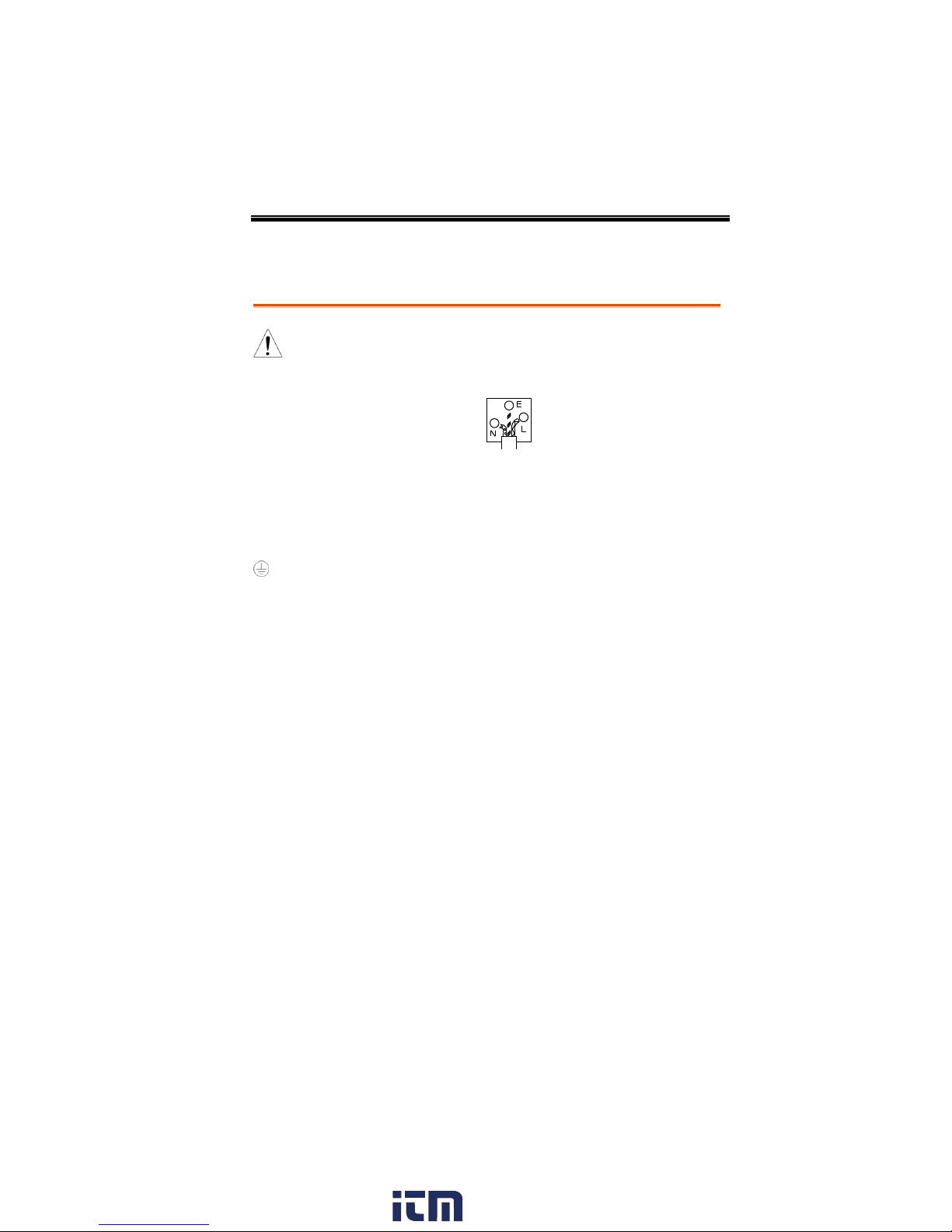
Power cord for the United Kingdom
When using the oscilloscope in the United Kingdom, make sure the
power cord meets the following safety instructions.
NOTE: This lead/appliance must only be wired by competent persons
WARNING: THIS APPLIANCE MUST BE EARTHED
IMPORTANT: The wires in this lead are coloured in accordance with the
following code:
As the colours of the wires in main leads may not correspond with
the coloured marking identified in your plug/appliance, proceed
as follows:
The wire which is coloured Green & Yellow must be connected to
the Earth terminal marked with either the letter E, the earth symbol
or coloured Green/Green & Yellow.
The wire which is coloured Blue must be connected to the terminal
which is marked with the letter N or coloured Blue or Black.
The wire which is coloured Brown must be connected to the
terminal marked with the letter L or P or coloured Brown or Red.
If in doubt, consult the instructions provided with the equipment
or contact the supplier.
This cable/appliance should be protected by a suitably rated and
approved HBC mains fuse: refer to the rating information on the
equipment and/or user instructions for details. As a guide, a cable
of 0.75mm2 should be protected by a 3A or 5A fuse. Larger
conductors would normally require 13A types, depending on the
connection method used.
Any exposed wiring from a cable, plug or connection that is
engaged in a live socket is extremely hazardous. If a cable or plug is
deemed hazardous, turn off the mains power and remove the cable,
any fuses and fuse assemblies. All hazardous wiring must be
immediately destroyed and replaced in accordance to the above
standard.
www. .com
9
information@itm.com1.800.561.8187

GDS-2000A Series User Manual
GDS-2000A Series Overview ............................................ 11
Series lineup .......................................................................... 11
Main Features ....................................................................... 12
Accessories ............................................................................ 13
Package Contents ................................................................. 15
Appearance ..................................................................... 16
GDS-2074A/2104A/2204A/2304A Front Panel ........... 16
GDS-2072A/2102A/2202A/2302A Front Panel ........... 17
Rear Panel ............................................................................. 24
Display ................................................................................... 26
Set Up ............................................................................. 29
Tilt Stand ............................................................................... 29
Module Installation .............................................................. 30
Software Installation ............................................................ 31
Power Up .............................................................................. 32
First Time Use ...................................................................... 33
How to Use This Manual .................................................... 35
GETTING STARTED
This chapter describes the GDS-2000A in a
nutshell, including its main features and front /
rear panel introduction. After going through the
overview, follow the Set Up section to properly
set up the oscilloscope for first time use. The Set
Up section also includes a starter on how to use
this manual effectively.
10
www. .com
information@itm.com1.800.561.8187

GETTING STARTED
Model name
Frequency
bandwidth
Input channels
Real-time
Sampling Rate
GDS-2072A
70MHz
2
2GSa/s
GDS-2102A
100MHz
2
2GSa/s
GDS-2202A
200MHz
2
2GSa/s
GDS-2302A
300MHz
2
2GSa/s
GDS-2074A
70MHz
4
2GSa/s
GDS-2104A
100MHz
4
2GSa/s
GDS-2204A
200MHz
4
2GSa/s
GDS-2304A
300MHz
4
2GSa/s
GDS-2000A Series Overview
Series lineup
The GDS-2000A series consists of 8 models, divided into 2-channel
and 4-channel versions.
www. .com
11
information@itm.com1.800.561.8187

Main Features
Features
8 inch TFT SVGA display.
MSO and DSO models available from 70MHz to
300MHz.
All models feature a real-time sampling rate of
2GSa/s and an equivalent time sampling rate of
100GSa/s.
Deep memory: 2M points record length.
Waveform capture rate of 80,000 waveforms per
second.
Vertical sensitivity: 1mV/div~10V/div.
Logic Analyzer module (optional): Adds 8 or 16
channel digital inputs and serial bus (I2C, SPI,
UART) and parallel bus triggering.
DDS Function Generator module (optional).
Segmented Memory: Optimizes the acquisition
memory to selectively capture only the
important signal details. Up to 2048 successive
waveform segments can be captured with a
time-tag resolution of 8ns. Segmented memory
can be used for both analog and digital
channels.
Enhanced Search: Allows the scope to search for
a number of different signal events.
On-screen Help.
64 MB internal flash disk.
GDS-2000A Series User Manual
12
www. .com
information@itm.com1.800.561.8187

Interface
USB host port: front and rear panel, for storage
devices.
USB device port: rear panel, for remote control
or printing.
Demo output
GPIB (optional)
RS232 port.
Calibration output
SVGA output and Ethernet port (optional)
Accessories
Standard
Accessories
Part number
Description
82DS-2304AM01
Quick Start Guide
N/A region dependent
Power cord
GTP-070A-4, for
GDS-2072A/GDS-2074A
Passive probe; 70 MHz
GTP-150A-2, for
GDS-2102A/GDS-2104A
Passive probe; 150 MHz
GTP-250A-2 for,
GDS-2202A/GDS-2204A
Passive probe; 250 MHz
GTP-350A-2 for,
GDS-2302A/GDS-2304A
Passive probe; 350 MHz
Options
Option
Number
Description
DS2-LAN
Ethernet & SVGA output
DS2-GPIB
GPIB Interface
DS2-FGN
DDS Function Generator
DS2-8LA
8-Channel Logic Analyzer card
(GLA-08)with 8-Channel Logic
Analyzer Probe (GTL-08LA)
GETTING STARTED
www. .com
13
information@itm.com1.800.561.8187

GDS-2000A Series User Manual
DS2-16LA
16-Channel Logic Analyzer card
(GLA-16)with 16-Channel Logic
Analyzer Probe (GTL-16A)
Optional
Accessories
Part number
Description
GTC-001
Instrument cart, 470(W)x430(D)mm
(U.S. type input socket)
GTC-002
Instrument cart, 330(W)x430(D)mm
(U.S. type input socket)
GTL-110
test lead, BNC to BNC heads
GTL-232
RS-232C cable, 9-pin Female to 9-pin
female, Null modem for computer
GTL-242
USB cable, USB2.0A-B type cable 4P
GTL-08LA
8-Channel Logic Analyzer Testing
Probe
GTL-16LA
16-Channel Logic Analyzer Testing
Probe
GLA-08
8-Channel Logic Analyzer Card
GLA-16
16-Channel Logic Analyzer Card
GTP-070A-4
Passive probe; 70 MHz
GTP-150A-2
Passive probe; 150 MHz
GTP-250A-2
Passive probe; 250 MHz
GTP-350A-2
Passive probe; 350 MHz
Drivers
USB driver
LabVIEW driver
14
www. .com
information@itm.com1.800.561.8187
GETTING STARTED
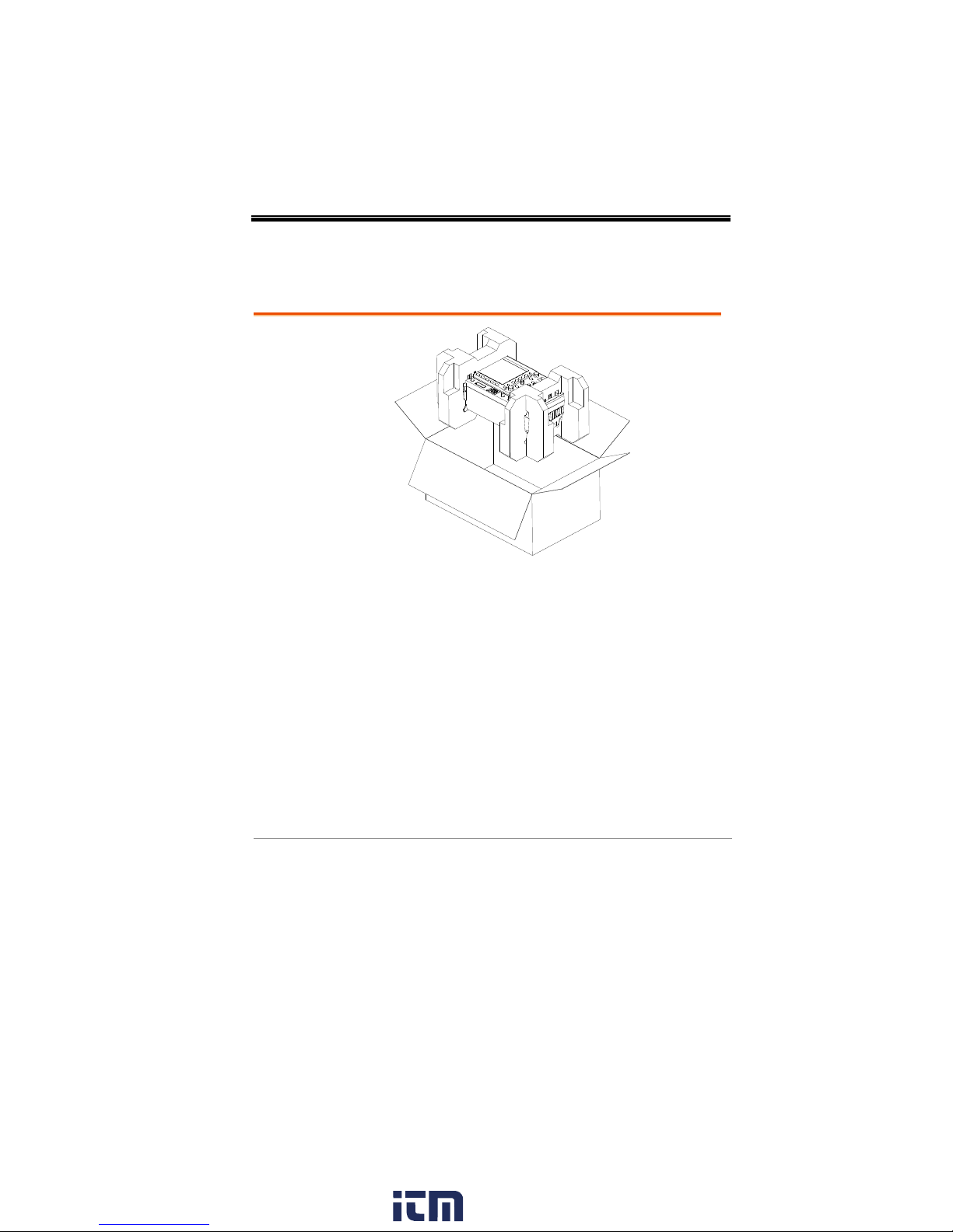
Opening the Box
Contents
Main unit
Probe set
GTP-070A-4 for GDS-2072A/ GDS-2074A
GTP-150A-2 for GDS-2102A / GDS-2104A
GTP-250A-2 for GDS-2202A / GDS-2204A
GTP-350A-2 for GDS-2302A / GDS-2304A
Power cord
Certificate of Traceable Calibration
User Manual CD
Quick Start Guide
Package Contents
Check the contents before using the GDS-2000A.
www. .com
15
information@itm.com1.800.561.8187
GDS-2000A Series User Manual
POWER
CH1 CH2
POSITION
TIME/DIV
POSITION
POSITION
VOLTS/DIV VOLTS/DIV
Autoset
Menu
50 %
Force-Trig
Select
TRIGGER
HORIZONTAL
VARIABLE
Measure Cursor
Display Help Save/Recall Utility
Acquire
Single
Run/Stop
Search
Set/Clear
CH3 CH4
POSITION
POSITION
VOLTS/DIV VOLTS/DIV
VERTICAL
M
R
B
Test
CH1 CH2 CH3 CH4 EXT TRIG
CAT
MW
16pF
300Vrms MAX.
1
CAT
MW
16pF
300Vrms MAX.
Hardcopy
Option
Menu Off
LEVEL
Zoom
MATH
REF
Demo
Logic Analyzer
1
BUS
Digital Storage Oscilloscope
GDS-2204A
200 MHz 2 GS/s
Visual Persistence Oscilloscope
GEN 1 GEN 2
Default
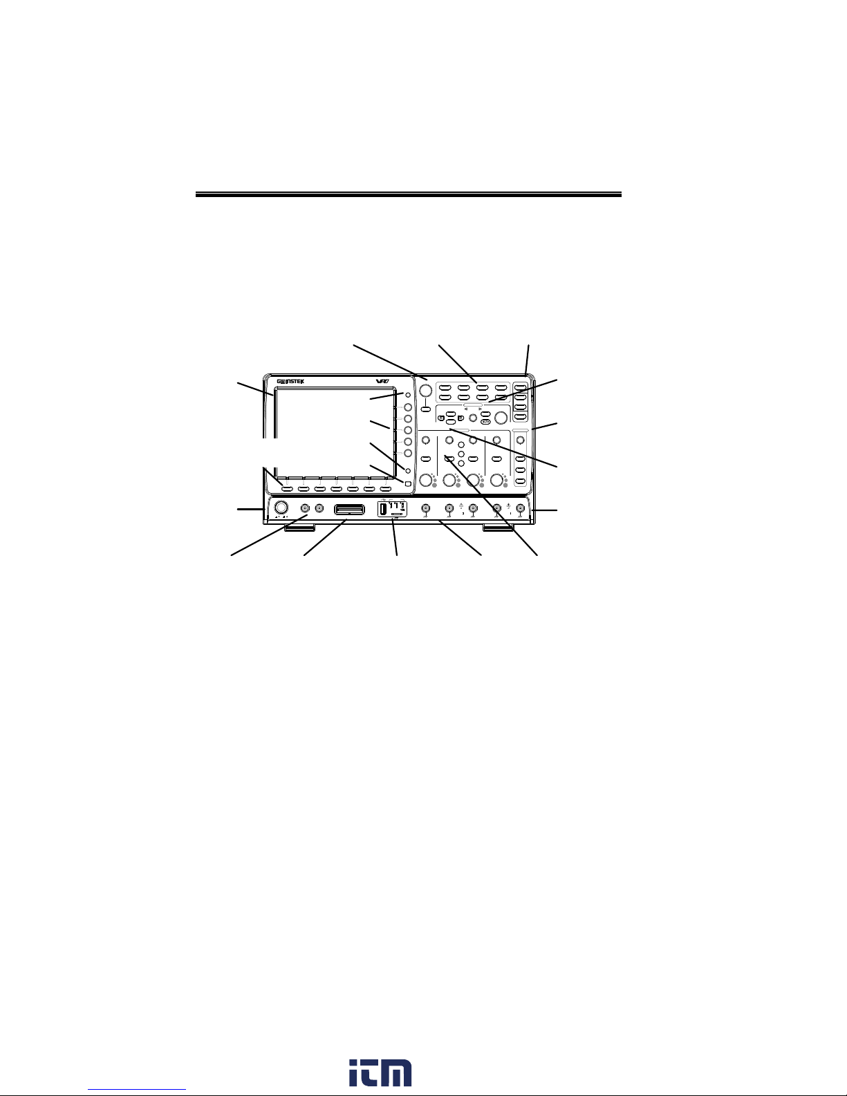
LCD
Variable knob
and Select key
Autoset, Run/Stop, Single
and Default settings
Math,
Reference and
Bus keys
Trigger
controls
Function
keys
USB Host port,
Demo and Ground
terminals
Function
Generator
output 1&2
Power
button
Hardcopy key
Option key
CH1~CH2
input
Bottom
menu keys
Horizontal
controls
Menu key
Vertical
controls
Logic
Analyzer
input
EXT
trigger
Side menu keys
Appearance
GDS-2074A/2104A/2204A/2304A Front Panel
16
www. .com
information@itm.com1.800.561.8187
GETTING STARTED
CH1 CH2
POSITION
TIME/DIV
POSITION
POSITION
VOLTS/DIV VOLTS/DIV
Autoset
Menu
50 %
Force-Trig
Select
TRIGGER
HORIZONTAL
VARIABLE
Measure Cursor
Display Help Save/Recall Utility
Acquire
Single
Run/Stop
LEVEL
Search
Set/Clear
VERTICAL
Test
POWER
2V
Hardcopy
Option
Menu Off
Zoom
CAT
M
16pF
300Vrms MAX.
1
CAT
MW
16pF
300Vrms MAX.
1
M
R
B
MATH
REF
BUS
Default
Logic Analyzer
GEN 1 GEN 2
CH1 CH2 EXT TRIG
Digital Storage Oscilloscope
GDS-2202A
200 MHz 2 GS/s
Visual Persistence Oscilloscope
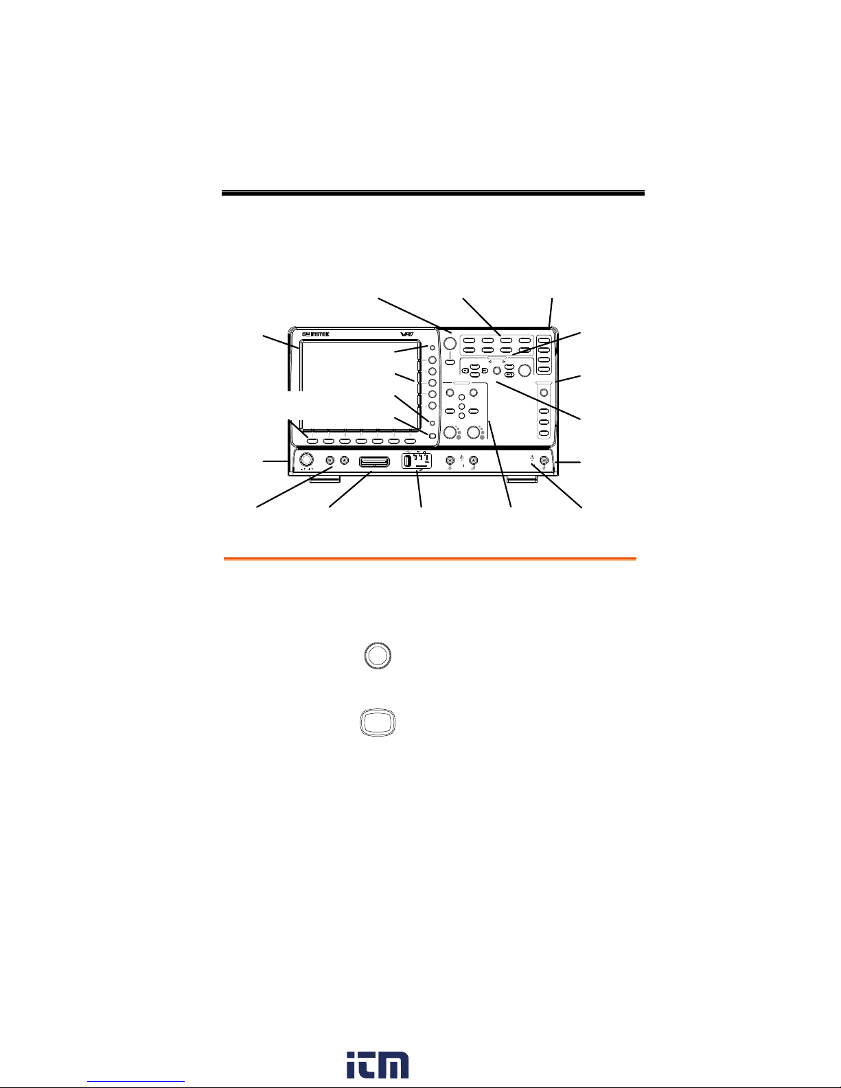
W
LCD
Variable knob
and Select key
Autoset, Run/Stop, Single
and Default settings
CH1~CH4
input
Trigger
controls
Function
keys
USB Host port,
Demo and Ground
terminals
Function
Generator
output 1&2
Power
button
Hardcopy key
Option key
Math,
Reference and
Bus keys
Bottom
menu keys
Horizontal
controls
Menu key
Vertical
controls
Logic
Analyzer
input
EXT
trigger
Side menu keys
LCD Display
8” SVGA TFT color LCD. 800 x 600 resolution,
wide angle view display.
Menu Off Key
Menu Off
Use the Menu Off key to hide the
onscreen menu system.
Option Key
Option
The Option key is used to access
any installed options, such the
Logic Analyzer option.
GDS-2072A/2102A/2202A/2302A Front Panel
www. .com
17
information@itm.com1.800.561.8187
GDS-2000A Series User Manual
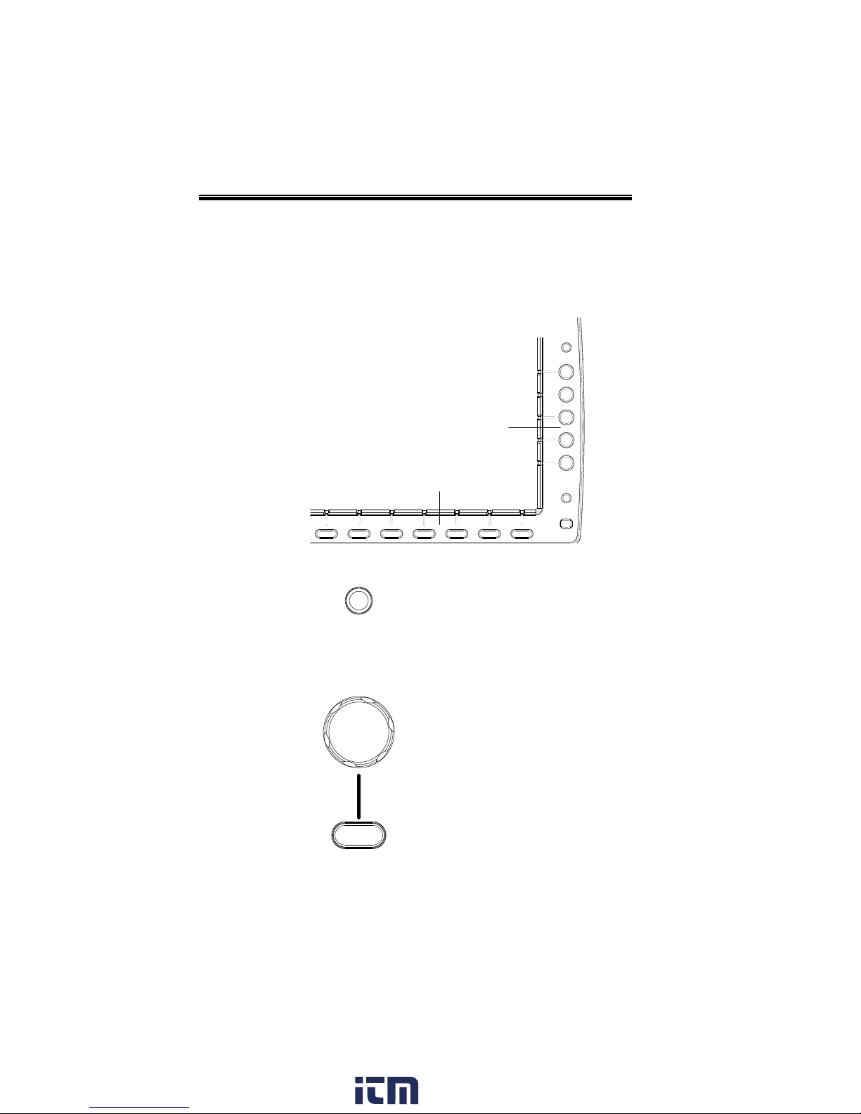
Menu Keys
The Side menu and Bottom menu keys are used to
make selections from the soft-menus on the LCD
user interface.
To choose menu items, use the 7 Bottom menu
keys located on the bottom of the display panel.
To select a variable or option from a menu, use the
Side menu keys on the side of the panel. See page
35 for details.
Hardcopy
Option
Menu Off
Side menu keys
Bottom menu keys
Hardcopy Key
Hardcopy
The Hardcopy key is a quick-save
or quick-print key, depending on
its configuration. For more
information see pages 220(save) or
219(print).
Variable Knob
and Select Key
Select
VARIABLE
The Variable knob is used to
increase/decrease values or to
move between parameters.
The Select key is used to make
selections.
18
www. .com
information@itm.com1.800.561.8187
GETTING STARTED
Function Keys
The Function keys are used to enter and configure
different functions on the GDS-2000A.
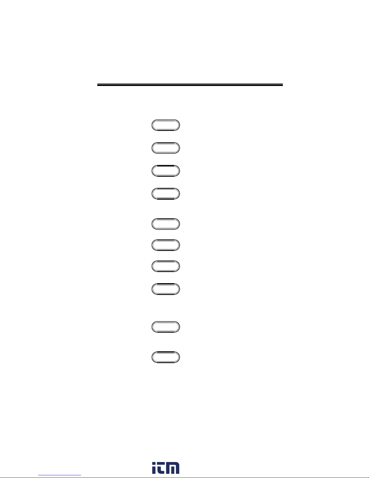
Measure
Measure
Configures and runs automatic
measurements.
Cursor
Cursor
Configures and runs cursor
measurements.
Test
Test
Configures and runs GW Instek
applications.
Acquire
Acquire
Configures the acquisition mode,
including Segmented Memory
acquisition.
Display
Display
Configures the display settings.
Help
Help
Shows the Help menu.
Save/Recall
Save/Recall
Used to save and recall
waveforms, images, panel settings.
Utility
Utility
Configures the Hardcopy key,
display time, language, calibration
and Demo outputs. It also
accesses the file utilities menu.
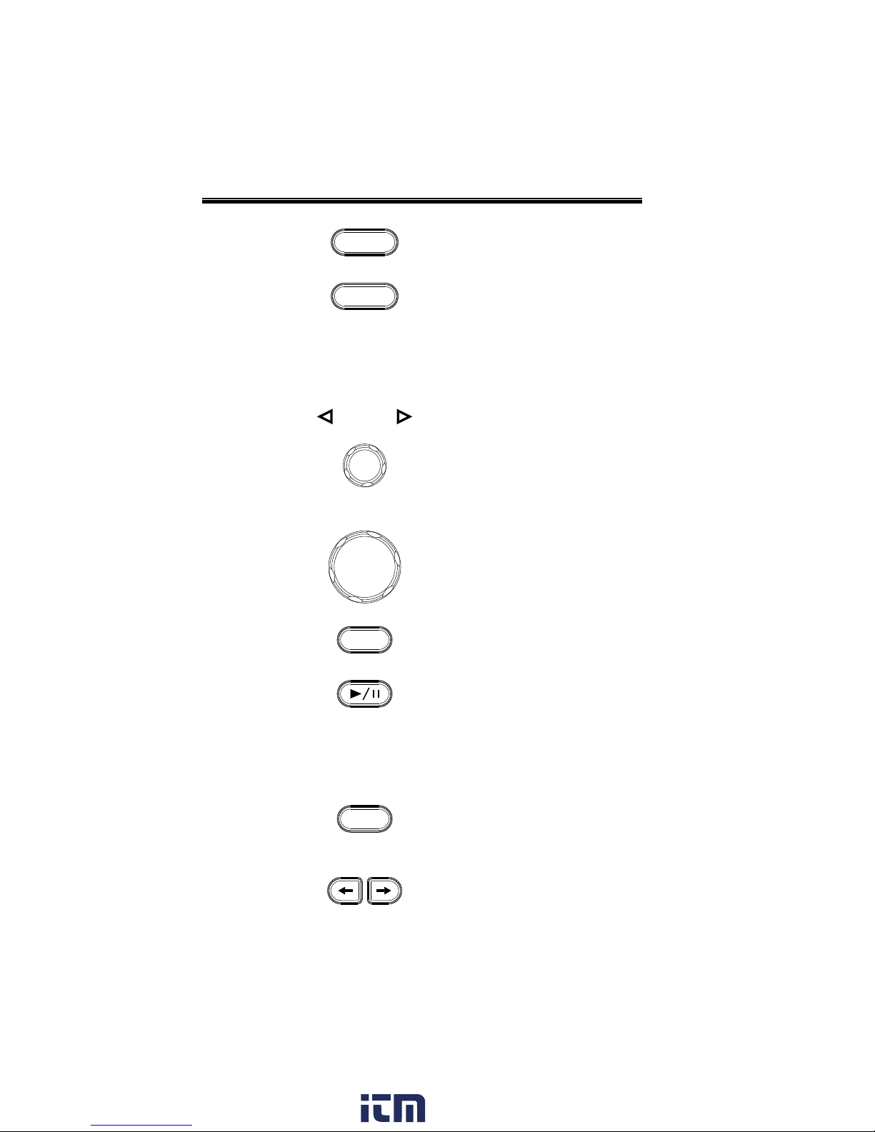
Autoset
Autoset
Press the Autoset key to
automatically set the trigger,
horizontal scale and vertical scale.
Run/Stop Key
Run/Stop
Press to Freeze (Stop) or continue
(Run) signal acquisition (page 68).
The run stop key is also used to
run or stop Segmented Memory
acquisition (page 114).
www. .com
19
information@itm.com1.800.561.8187
GDS-2000A Series User Manual
Single
Single
Sets the acquisition mode to single
triggering mode.
Default Setup
Default
Resets the oscilloscope to the
default settings.
Horizontal
Controls
The horizontal controls are used to change the
position of the cursor, set the time base settings,
zoom into the waveforms and search for events*.
Horizontal
Position
POSITION
The Position knob is used to
position the waveforms
horizontally on the display screen.
TIME/DIV
TIME/DIV
The Time/Div knob is used to
change the horizontal scale.
Zoom
Zoom
Press Zoom in combination with
the horizontal Position knob.
Play/Pause
The Play/Pause key allows you to
view each search event in
succession – to effectively “play”
through each search event. It is
also used to play through a
waveform in zoom mode.
Search
Search
The Search key accesses the search
function menu to set the search
type, source and threshold.
Search Arrows
Use the arrow keys to navigate the
search events.
20
www. .com
information@itm.com1.800.561.8187

GETTING STARTED
Set/Clear
Set/Clear
Use the Set/Clear key to set or
clear points of interest when using
the search function.
Trigger Controls
The trigger controls are used to control the trigger
level and options.
Level Knob
LEVEL
Used to set the trigger level.
Trigger Menu Key
Menu
Used to bring up the trigger menu.
50% Key
50 %
Sets the trigger level to the half
way point (50%).
Force - Trig
Force-Trig
Press to force an immediate trigger
of the waveform.
Vertical
POSITION
POSITION
Sets the vertical position of the
waveform.
Channel Menu
Key
CH1
Press the CH1~4 key to set and
configure the channel.
VOLTS/DIV Knob
VOLTS/DIV
Sets the vertical scale of the
channel.
www. .com
21
information@itm.com1.800.561.8187
GDS-2000A Series User Manual
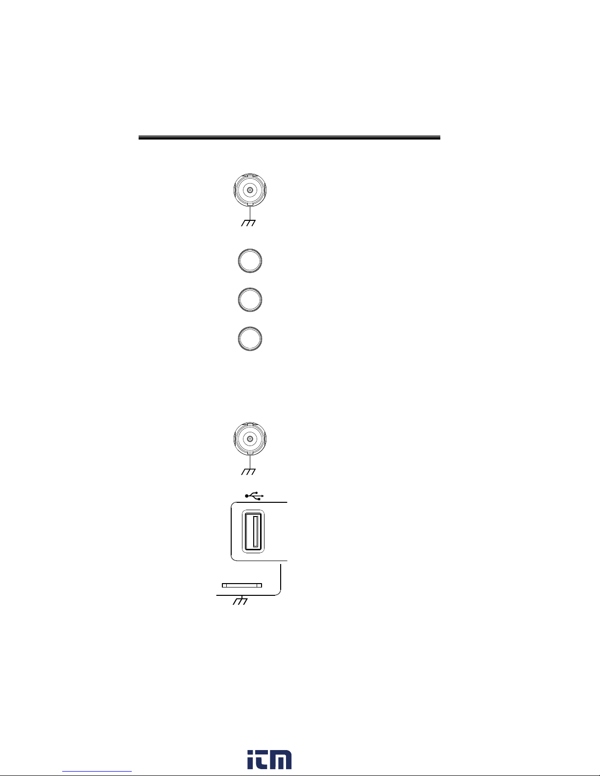
External Trigger
Input
EXT TRIG
Accepts external trigger signals
(page 144).
Input impedance: 1MΩ
Voltage input: ±15V(peak), EXT
trigger capacitance:16pF.
Math Key
M
MATH
Use the math key to set and
configure math functions.
Reference Key
R
REF
Press the Reference key to set or
remove reference waveforms.
BUS Key
B
BUS
The Bus key is used for parallel
and serial bus (UART, I2C and SPI)
configuration. Serial bus and
parallel bus functionality is
included with the Logic Analyzer
options (DS2-8LA/DS2-16LA).
Channel Inputs
CH1
Accepts input signals.
Input impedance: 1MΩ.
USB Host Port
Demo
TypeA, 1.1/2.0 compatible. Used
for data transfer.
Ground Terminal
Demo
Accepts the DUT ground lead for
common ground.
22
www. .com
information@itm.com1.800.561.8187
GETTING STARTED
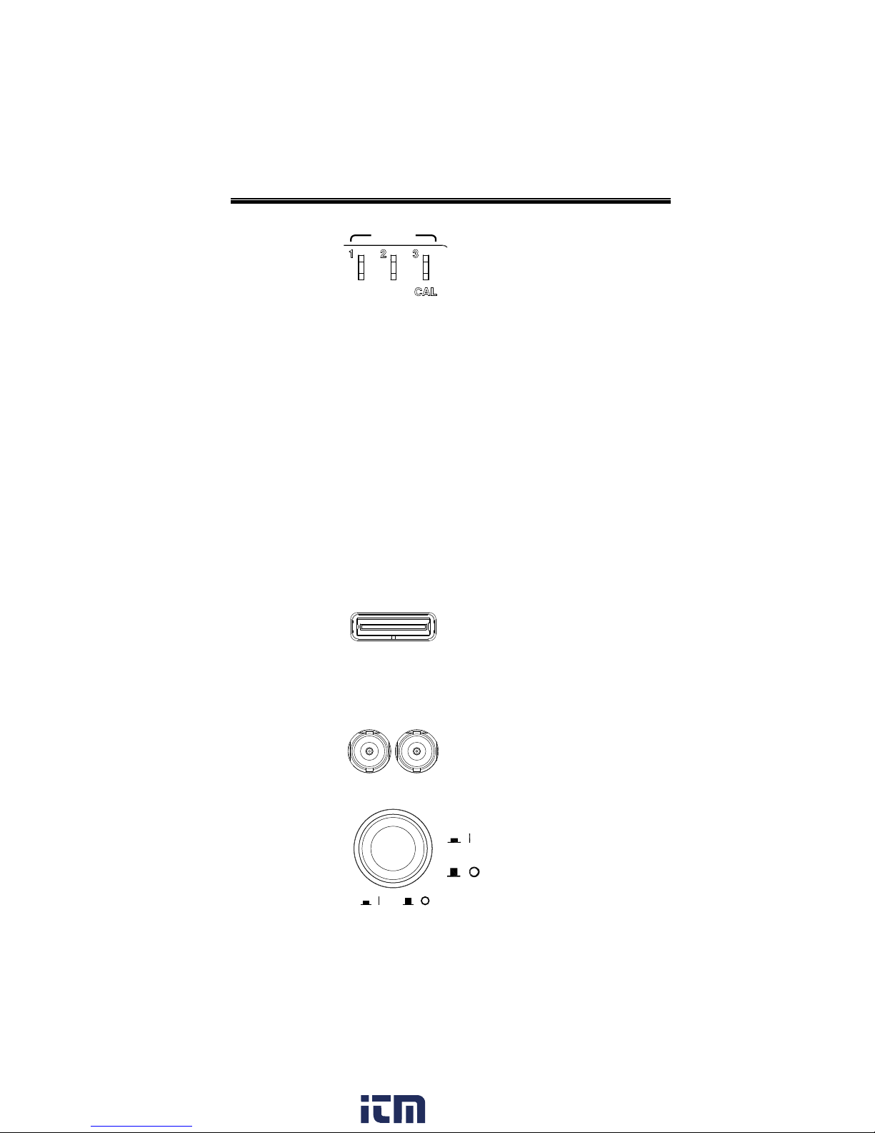
Demo and Probe
Compensation
Outputs
Demo
The Demo outputs are
multifunction outputs that can be
configured for probe
compensation, as a trigger output
or as a basic waveform generator
for demonstration purposes. (FM
signal, UART, I2C, SPI).
By default, the 3 Demo outputs are
configured as:
1: Trigger output
2: FM waveform
3: Probe Compensation signal
CAL (Demo 3) outputs a 2Vp-p,
square wave signal for probe
compensation.
Please see page 171 for details.
Logic Analyzer
Port
Logic Analyzer
The Logic Analyzer port is used to
connect to a Logic Analyzer probe.
This port only functions if the
optional logic analyzer module is
installed.
Function
Generator Output
GEN 1
GEN 2
The function generator outputs are
used with an optional function
generator module.
Power Switch
POWER
Used to turn the power on/off.
: ON
: OFF
www. .com
23
information@itm.com1.800.561.8187
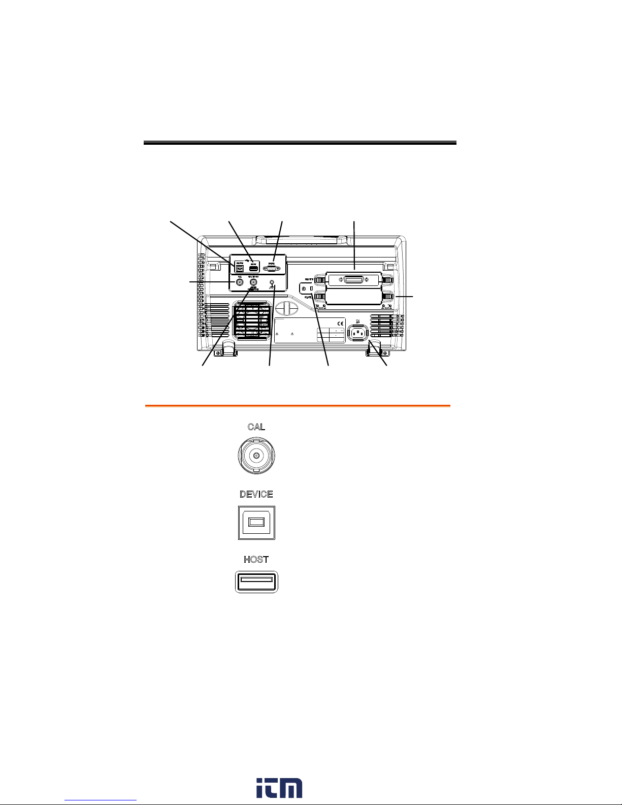
Rear Panel
LINE VOLTAGE
AC 100 240V
RANGE
FREQUENCY 50 60Hz
POWER MAX. 55W 80VA
CAUTION
TO AVOID ELECTRIC SHOCK THE POWER CORD PROTECTIVE GROUNDING
DO NOT REMOVE COVERS. REFER SERVICING TO QUALIFIED PERSONNEL.
CONDUCTOR MUST BE CONNECTED TO GROUND.
Ser. No. Label
Calibration
output
RS232
port Module Slot 1
Module
Slot 2
Key lock Power input
socket
Ground strap
connector
Go/No Go
output
USB Host
port
USB Device
port
Calibration
Output
Outputs the signal for vertical scale
accuracy calibration (page 243).
USB Device Port
The USB Device port is used for
remote control.
USB Host Port
The USB Host port is used to data
transfer.
Note: Only one rear panel USB port
can be used at a time. Inserting a USB
flash drive into the USB Host Port will
disable the USB Device Port, and vice
versa.
GDS-2000A Series User Manual
24
www. .com
information@itm.com1.800.561.8187
GETTING STARTED
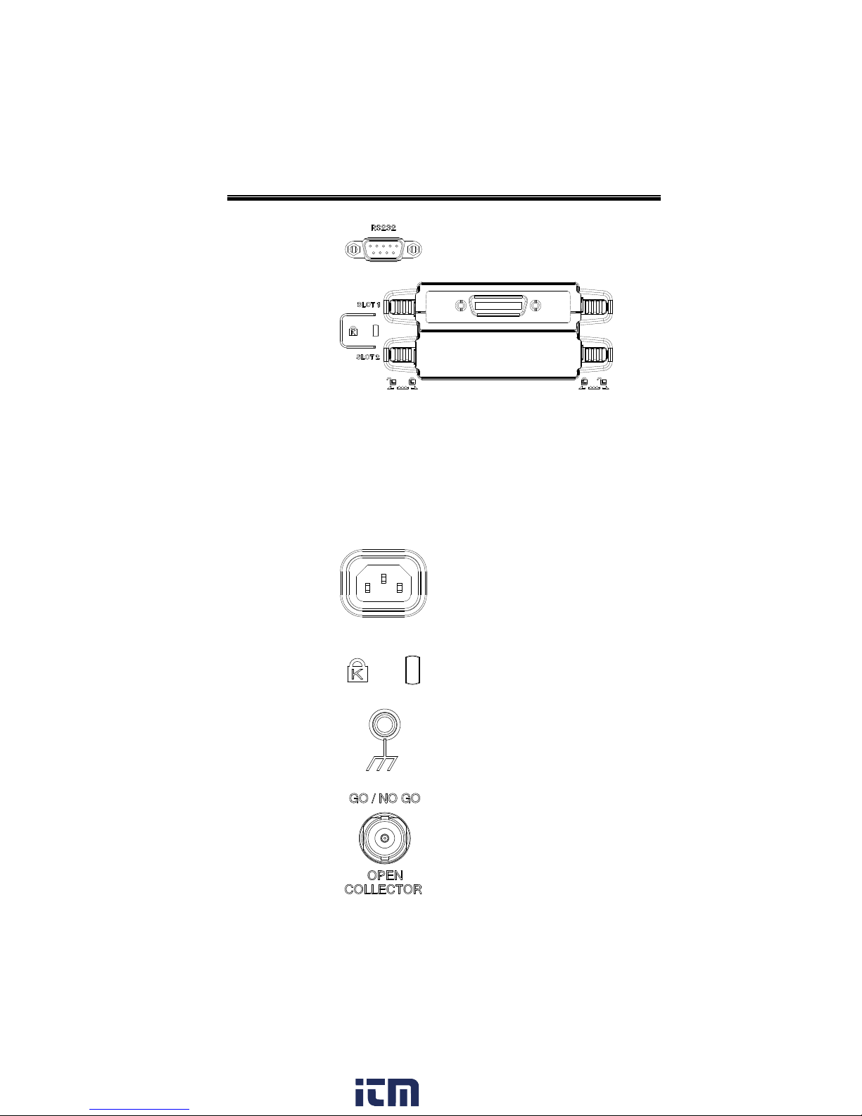
RS232 Port
Used for RS-232-based remote
control.
Module Slots
The module slots are used to install the optional
modules:
DS2-LAN: Ethernet and SVGA
DS2-GPIB: GPIB
GLA-08: 8 channel logic analyzer
GLA-16: 16 channel logic analyzer
Power Input
Socket
Power cord socket accepts AC
mains, 100 ~ 240V, 50/60Hz.
For power up sequence, see page
32.
Security Slot
Kensington security slot
compatible.
Ground Strap
Connector
For use with a grounding strap.
Go-No Go
Output
Outputs Go-No Go test results
(page 177) as a 500us pulse signal.
www. .com
25
information@itm.com1.800.561.8187
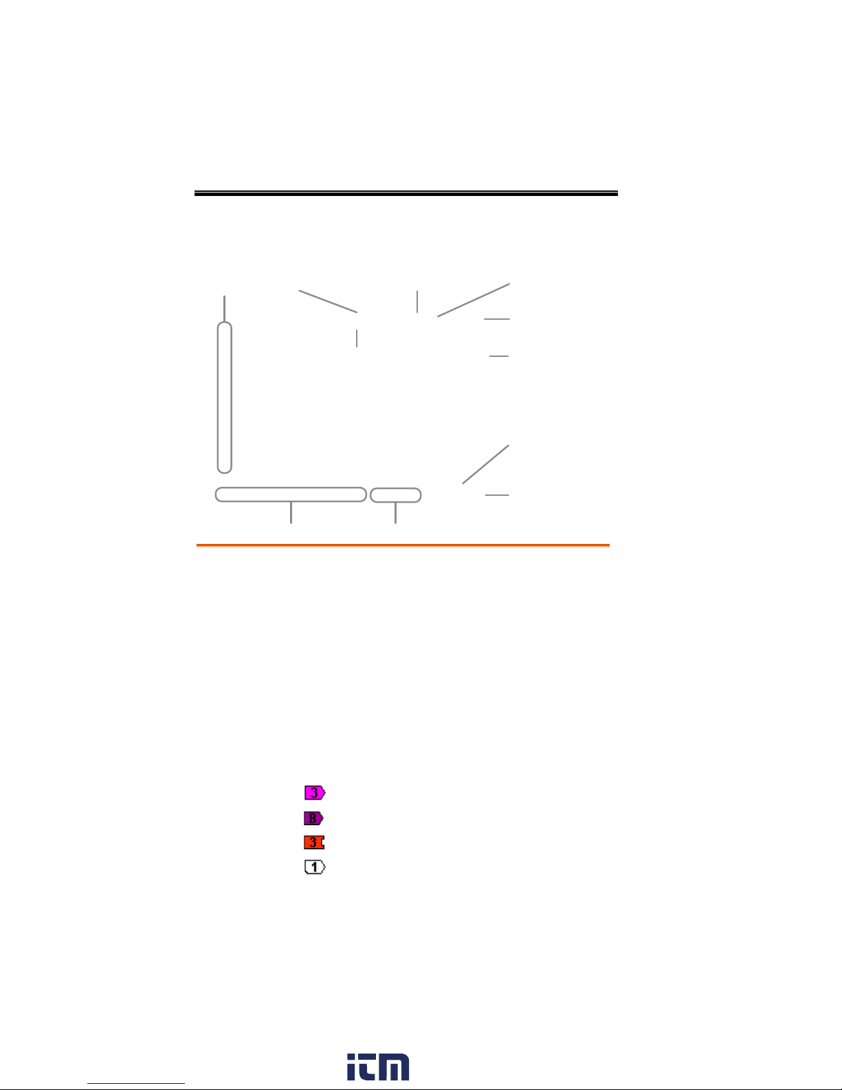
Display
Memory bar
Digital
waveforms
Analog
Waveforms
Bus
Channel status Horizontal status
Trigger
configuration
Waveform
frequency
Date and time
Trigger position
Acquisition modeTrigger Status
Trigger level
Channel
Indicators
Analog
Waveforms
Shows the analog input signal waveforms.
Channel 1: Yellow
Channel 2: Blue
Channel 3: Pink
Channel 4: Green
Bus Waveforms
Shows the bus waveforms for either parallel or
serial buses. The values are displayed in hex or
binary.
Digital
Waveforms
Shows the digital channel waveforms. There can
be up to 16 digital channels.
Channel
Indicators
The channel indicators show the zero volt level of
the signal waveform for each activated channel.
Any active channel is shown with a solid color.
Analog channel indicator
Bus indicator(B)
Digital channel indicator
Reference waveform indicator
GDS-2000A Series User Manual
26
www. .com
information@itm.com1.800.561.8187
GETTING STARTED
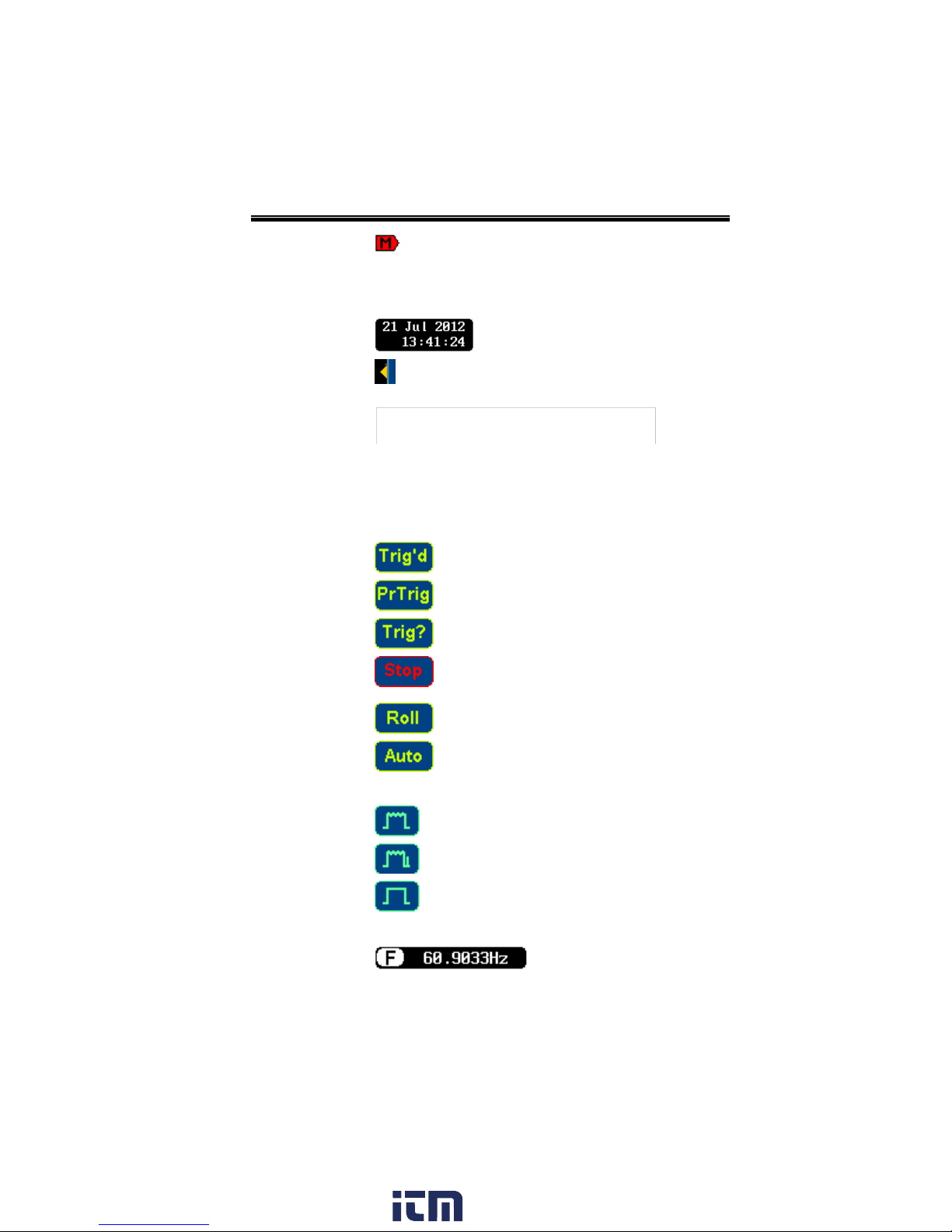
Math indicator
Trigger Position
Shows the position of the trigger.
Horizontal Status
Shows the horizontal scale and position.
Date and Time
Current date and time (page 170).
Trigger Level
Shows the trigger level on the
graticule.
Memory Bar
The ratio and the position of the
displayed waveform compared
with the internal memory (page
130).
Trigger Status
Triggered.
Pre-trigger.
Not triggered, display not updated.
Trigger stopped. Also appears in
Run/Stop (page 68).
Roll mode.
Auto trigger mode.
For trigger details, see page 144.
Acquisition Mode
Normal mode
Peak detect mode
Average mode
For acquisition details, see page 103.
Signal Frequency
Shows the trigger source
frequency.
www. .com
27
information@itm.com1.800.561.8187
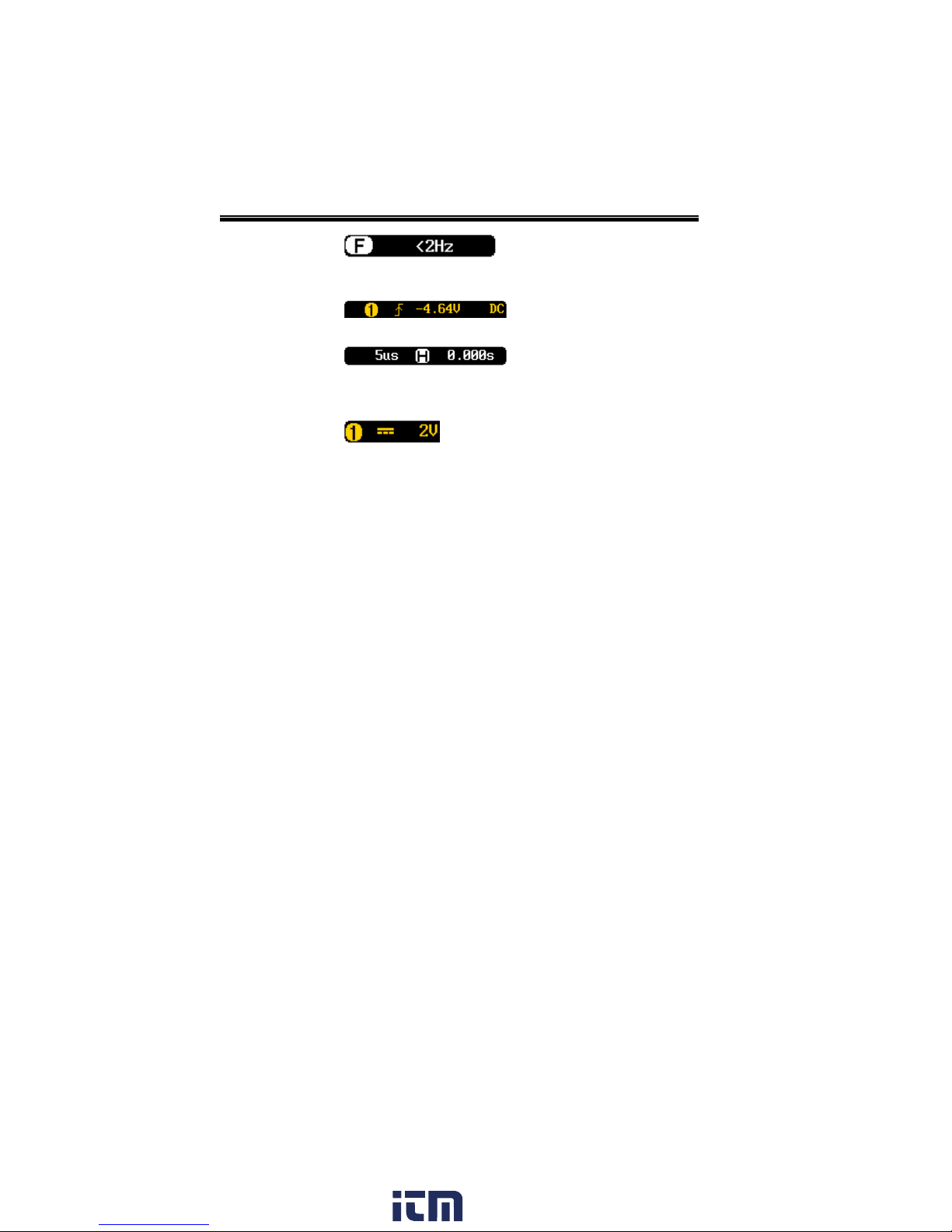
GDS-2000A Series User Manual
Indicates the frequency is
less than 2Hz (lower
frequency limit).
Trigger
Configuration
Trigger source, slope,
voltage, coupling.
Horizontal Status
Horizontal scale,
horizontal position.
For trigger details, see page 144.
Channel Status
Channel 1, DC coupling,
2V/Div.
For channel details, see page 137.
28
www. .com
information@itm.com1.800.561.8187
Set Up
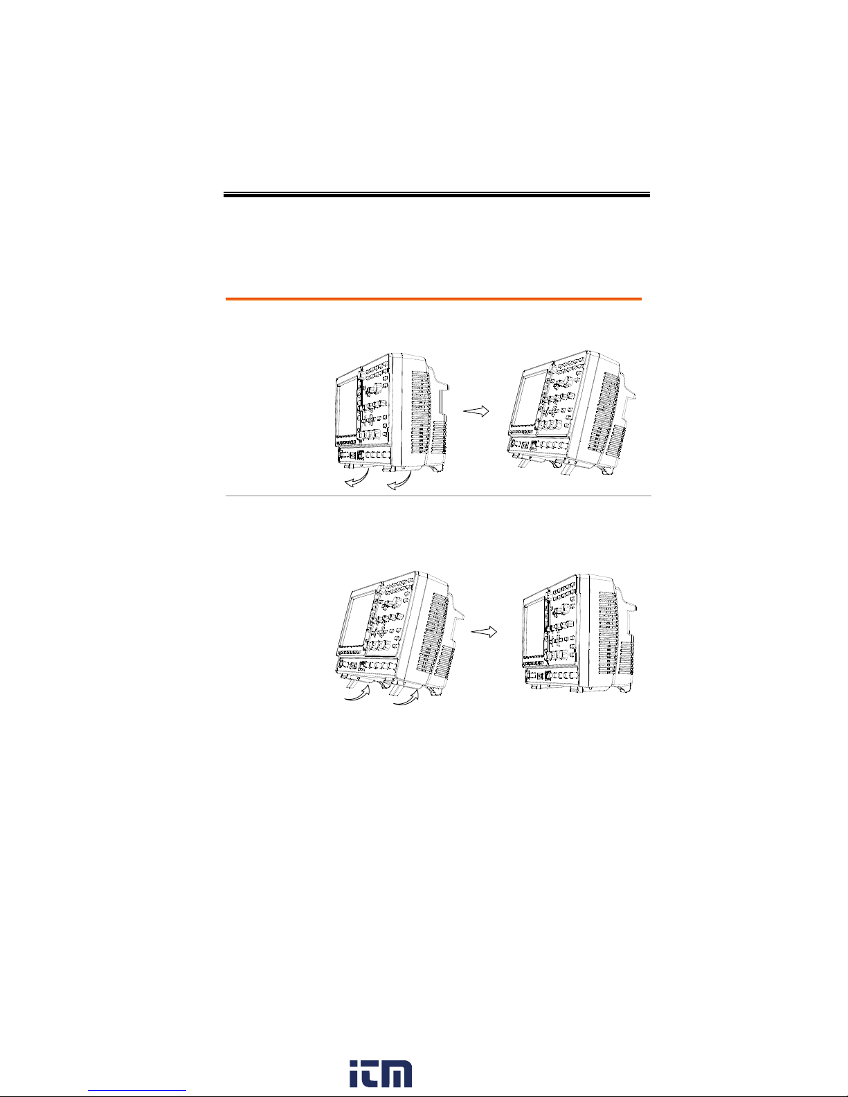
Tilt
To tilt, pull the legs forward, as shown below.
Stand
To stand the scope upright, push the legs back
under the casing as shown below.
Tilt Stand
GETTING STARTED
www. .com
29
information@itm.com1.800.561.8187
GDS-2000A Series User Manual
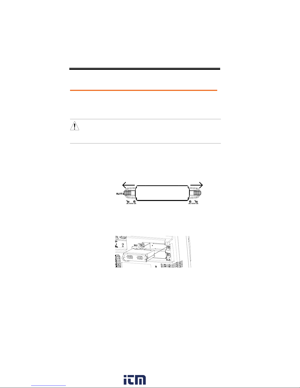
Background
The GDS-2000A has a number of optional modules
that can be installed into the module slots on the
rear panel. These modules must be installed before
power up.
Note
The modules are not hot-swappable. Please ensure the
power is off before connecting or disconnecting any of
the modules from the rear panel.
Steps
1. Make sure the power is turned off before
installing any of the optional modules.
2. Slide the tabs holding the module cover to the
unlock position and then remove
3. Install the optional module. Be sure to make
sure that the groves on the module line-up to
the slots in the module bay.
4. Slide the tabs back into the lock position.
Module Installation
30
www. .com
information@itm.com1.800.561.8187
 Loading...