

Page 1

Digital Storage Oscilloscope
GDS-2000A Series
PROGRAMMING MANUAL
GW INSTEK PART NO. Version 1.0, October 2012
ISO-9001 CERTIFIED MANUFACTURER
Page 2

October 2012
This manual contains proprietary information which is protected by
copyright. All rights are reserved. No part of this manual may be
photocopied, reproduced or translated to another language without
prior written consent of Good Will Corporation.
The information in this manual was correct at the time of printing.
However, Good Will continues to improve products and reserves the
right to change specifications, equipment, and maintenance
procedures at any time without notice.
Windows is a registered trademark of Microsoft Corporation in the United States and other countries.
Good Will Instrument Co., Ltd.
No. 7-1, Jhongsing Rd., Tucheng Dist., New Taipei City 236, Taiwan.
Page 3

TABLE OF CONTENTS
Table of Contents
INTERFACE OVERVIEW ..................................................... 5
Front Panel Overview ................................. 5
Interface Configuration .............................. 6
COMMAND OVERVIEW .................................................. 21
COMMAND OVERVIEW .................................................. 21
Command Syntax ..................................... 21
List of Commands in Functional Order .... 23
COMMAND DETAILS ...................................................... 33
Common Commands ............................... 35
Acquisition Commands ............................ 39
Autoscale Commands .............................. 44
Vertical Commands .................................. 45
Math Commands ..................................... 51
Cursor Commands ................................... 59
Display Commands .................................. 69
Hardcopy Commands .............................. 72
Measure Commands ................................ 76
Measurement Commands ........................ 99
Reference Commands ............................. 106
Run Command ........................................ 109
Stop Command ....................................... 109
Single Command ..................................... 109
Force Command ...................................... 110
Timebase Commands .............................. 111
Trigger Commands .................................. 114
System Commands ................................. 146
Save/Recall Commands .......................... 147
Ethernet Commands ............................... 153
3
Page 4

GDS-2000AA Programming Manual
Time Commands .................................... 154
Bus Decode Commands ......................... 155
Mark Commands .................................... 166
Search Commands ................................. 168
Digital Commands ................................. 192
Label Commands ................................... 199
Utility Commands .................................. 207
APPENDX ....................................................................... 208
Error messages ...................................... 208
INDEX ............................................................................ 212
Page 5
INTERFACE OVERVIEW
POWER
CH1 CH2
POSITION
TIME/DIV
POSITION
POSITION
VOLTS/DIV VOLTS/DIV
Autoset
Menu
50 %
Force-Trig
Select
TRIGGER
HORIZONTAL
VARIABLE
Measure Cursor
Display Help Save/Recall Utility
Acquire
Single
Run/Stop
Search
Set/Clear
CH3 CH4
POSITION
POSITION
VOLTS/DIV VOLTS/DIV
VERTICAL
M
R
B
Test
CH1 CH2 CH3 CH4 EXT TRIG
CAT
MW16pF
300Vpk MAX.
1
CAT
MW16pF
300Vpk MAX.
Hardcopy
Option
Menu Off
LEVEL
Zoom
MATH
REF
Demo
Logic Analyzer
1
BUS
Digital Storage Oscilloscope
GDS-2204A
200 MHz 2 GS/s
Visual Persistence Oscilloscope
GEN 1 GEN 2
Default
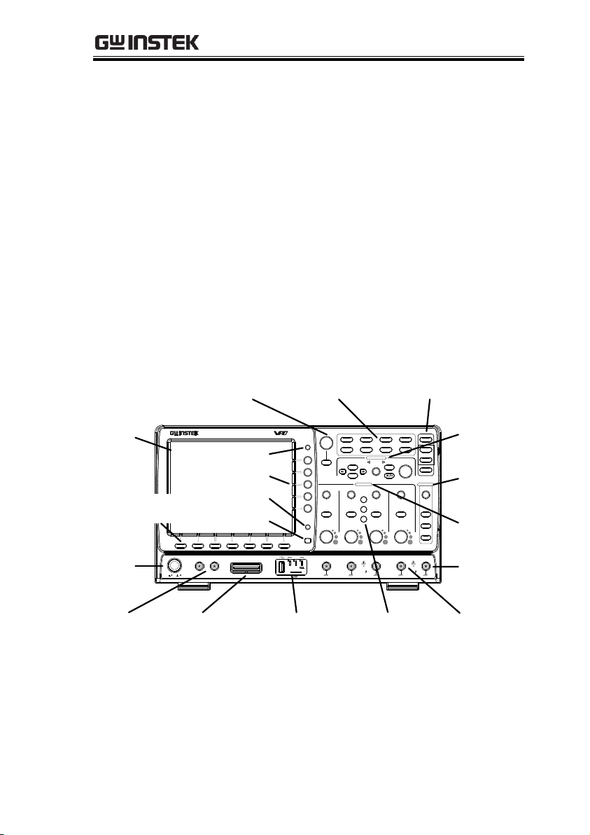
LCD
Variable knob
and Select key
Autoset, Run/Stop, Single
and Default settings
CH1~CH4
input
Trigger
controls
Function
keys
USB Host port,
Demo and Ground
terminals
Function
Generator
output 1&2
Power
button
Hardcopy key
Option key
Math,
Reference and
Bus keys
Bottom
menu keys
Horizontal
controls
Menu key
Vertical
controls
Logic
Analyzer
input
EXT
trigger
Side menu keys
INTERFACE OVERVIEW
This manual describes how to use the
GDS-2000A’s remote command functionality and
lists the command details. The Overview chapter
describes how to configure the GDS-2000A USB
remote control interface, Ethernet interface, GPIB
interface and RS-232 interface.
Front Panel Overview
4 channel model shown.
5
Page 6
GDS-2000A Programming Manual
USB
Configuration
PC side connector
Type A, host
GDS-2000A side
connector
Type B, device
Speed
1.1/2.0 (high speed)
USB Class
CDC (communications device
class)
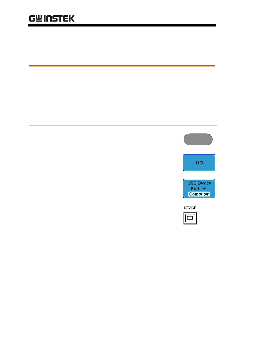
Panel Operation
1. Press the Utility key.
Utility
2. Press I/O from the bottom menu.
3. Press USB Device Port from the side
menu and select Computer.
4. Connect the USB cable to the rear
panel device port.
5. When the PC asks for the USB driver, select the
USB driver included on the accompanying User
Manual CD or download the driver from the
GW Instek website, www.gwinstek.com, in the
GDS-2000A product corner. The driver
automatically sets the GDS-2000A as a serial
COM port.
Interface Configuration
Configure USB Interface
6
Page 7
INTERFACE OVERVIEW
RS-232C
Configuration
Connector
DB-9, Male
Baud rate
2400, 4800, 9600, 19200, 38400,
57600, 115200
Parity
None, Odd, Even
Data bit
8 (fixed)
Stop bit
1, 2
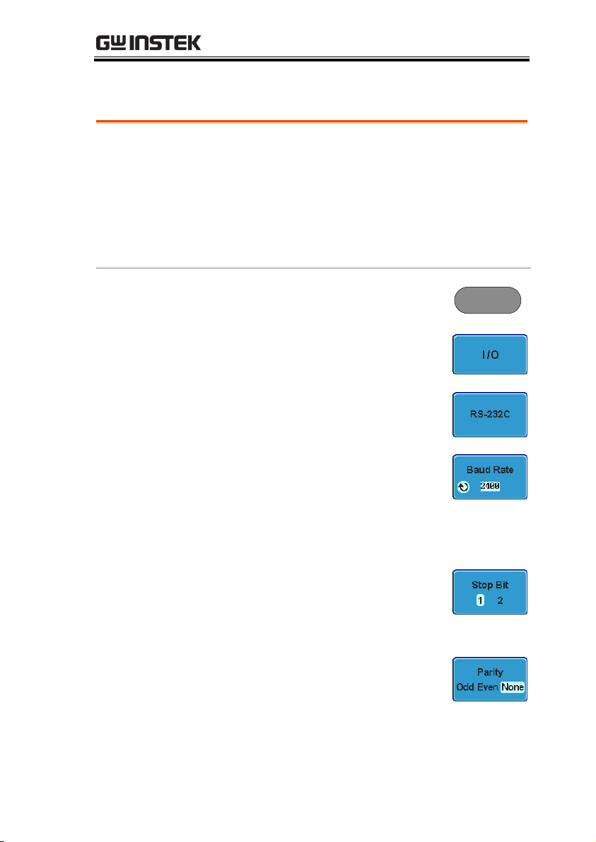
Panel Operation
1. Press the Utility key.
Utility
2. Press I/O from the bottom menu.
3. Press RS-232C from the side menu.
4. Use the side menu to set the Baud
Rate.
Baud Rate
2400, 4800, 9600, 19200, 38400,
57600, 115200
5. Press Stop Bit to toggle the number
of stop bits.
Stop Bits
1, 2
6. Press Parity to toggle the parity.
Parity
Odd, Even, None
Configure RS-232C Interface
7
Page 8
GDS-2000A Programming Manual
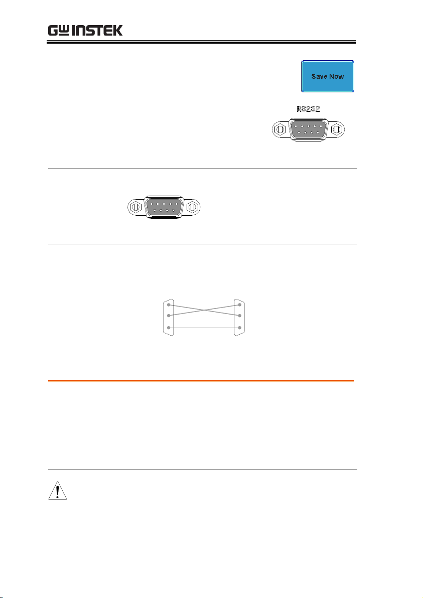
7. Press Save Now to save the settings.
8. Connect the RS-232C cable
to the rear panel port: DB-9
male connector. For a
functionality check, see page
13.
Pin Assignment
1
2345
6789
2: RxD (Receive data)
3: TxD (Transmit data)
5: GND
4, 6 ~ 9: No connection
PC Connection
Use a Null Modem connection as shown in the
diagram below.
GDS-2000A PC
RxDPin2 RxD Pin2
GNDPin5 GND Pin5
TxD Pin3
TxDPin3
Ethernet
Configuration
MAC Address
Domain Name
Instrument Name
DNS IP Address
User Password
Gateway IP Address
Instrument IP
Address
Subnet Mask
HTTP Port 80 (fixed)
Note
The Ethernet option, DS2-LAN, must first be installed
before proceeding. Please the user manual for further
details.
Configure the Ethernet Interface
8
Page 9
INTERFACE OVERVIEW
Background
The Ethernet interface is used for remote
configuration of the oscilloscope over a network
using the integrated web server or for remote
control using a socket server connection. For
details, please see the Web Server Configuration
section in the user manual or the Socket Server
section on page 11.
Panel Operation
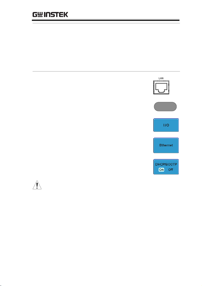
1. Connect the Ethernet cable to the
LAN port on the DS2-LAN
module.
2. Press the Utility key.
Utility
3. Press I/O from the bottom menu.
4. Press Ethernet from the side menu.
5. Set DHCP/BOOTP to On or Off
from the side menu.
Note
IP addresses will automatically be assigned with
DHCP/BOOTP set to on. For Static IP Addresses,
DHCP/BOOTP should be set to off.
9
Page 10
GDS-2000A Programming Manual
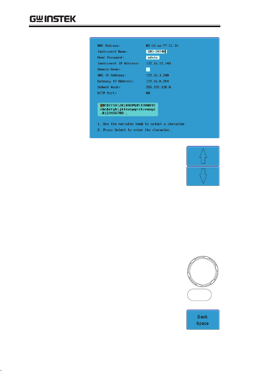
6. Use the Up and Down arrows on
the side menu to navigate to each
Ethernet configuration item.
Items
MAC Address, Instrument Name,
User Password, Instrument IP
Address, Domain Name, DNS IP
Address, Gateway IP Address,
Subnet Mask
Note: HTTP Port is fixed at 80.
7. Use the Variable knob to highlight a
character and use the Select key to
choose a character.
VARIABLE
Select
Press Backspace to delete a
character.
10
Page 11
INTERFACE OVERVIEW
Configure Socket Server
1. Configure the IP address for the
GDS-2000A.
Page 7
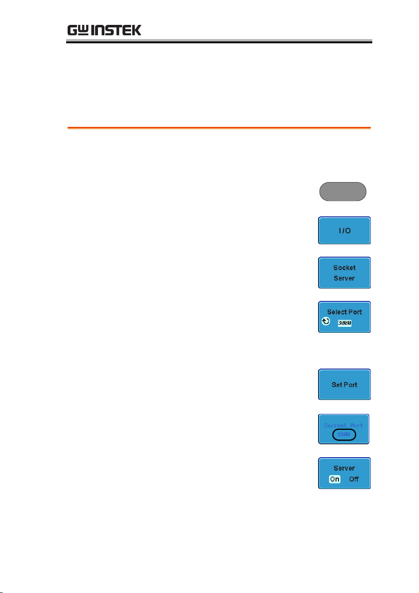
2. Press the Utility key.
Utility
3. Press I/O from the bottom menu.
4. Press Socket Server from the side
menu.
5. Press Select Port and choose the
port number with the Variable
knob.
Range
1024~65535
6. Press Set Port to confirm the port
number.
7. The Current Port icon will update
to the new port number.
8. Press Server and turn the socket
server On.
Configure Socket Server
The GDS-2000A supports socket server functionality for direct twoway communication with a client PC or device over LAN. By default,
the Sockets Server is off.
11
Page 12
GDS-2000A Programming Manual
Note
To use GPIB, the optional module, DS2-GPIB, must be
installed. Please see the user manual for installation
details.
Connection
1. Connect a GPIB cable from a PC to the installed
GPIB module.
Configure GPIB
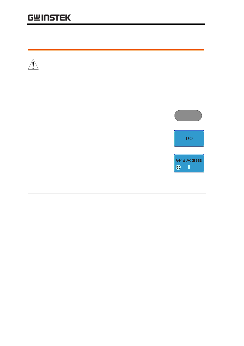
2. Press the Utility key.
Utility
3. Press I/O from the bottom menu.
4. Use the Variable knob to set the
GPIB Address from the side menu.
This option will only be available
when the GPIB module is installed.
Range
1 ~ 30
GPIB Constraints
Maximum 15 devices altogether, 20m cable
length, 2m between each device
Unique address assigned to each device
At least 2/3 of the devices turned On
No loop or parallel connection
Configure GPIB
12
Page 13
INTERFACE OVERVIEW
Terminal
Application
(USB/RS-232C)
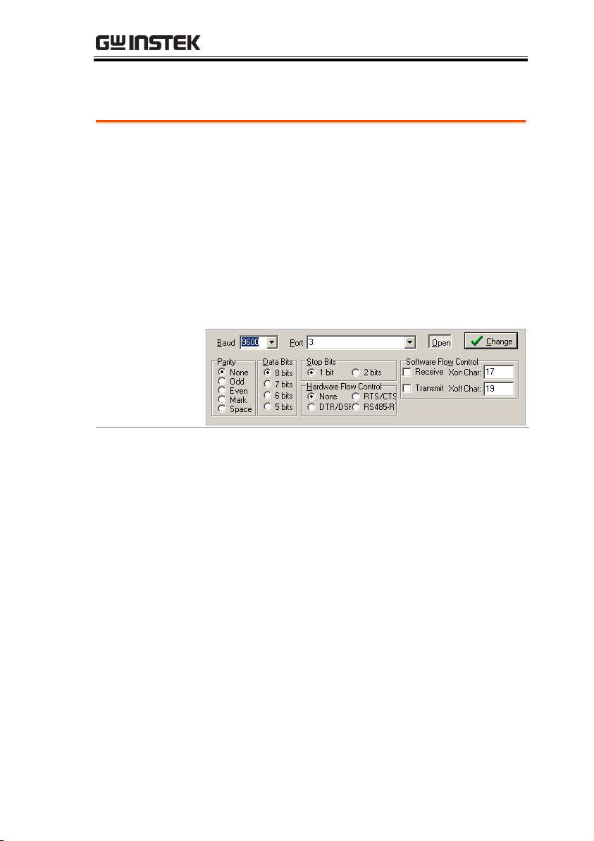
Invoke a terminal application such as RealTerm.
For RS-232C and USB, set the COM port, baud
rate, stop bit, data bit, and parity accordingly.
To check the COM port number and associated
port settings, see the Device Manager in the PC.
For WinXP:
Control panel → System → Hardware tab
Example: Configuring RealTerm for RS232C
communication.
Functionality
Check
Key in this query command via the terminal
application.
*idn?
This should return the Manufacturer, Model
number, Serial number, and Firmware version in
the following format.
GW, GDS-2074A, PXXXXXX, V1.00
USB/RS-232C Functionality Check
13
Page 14
GDS-2000A Programming Manual
NI Measurement
and Automation
Explorer
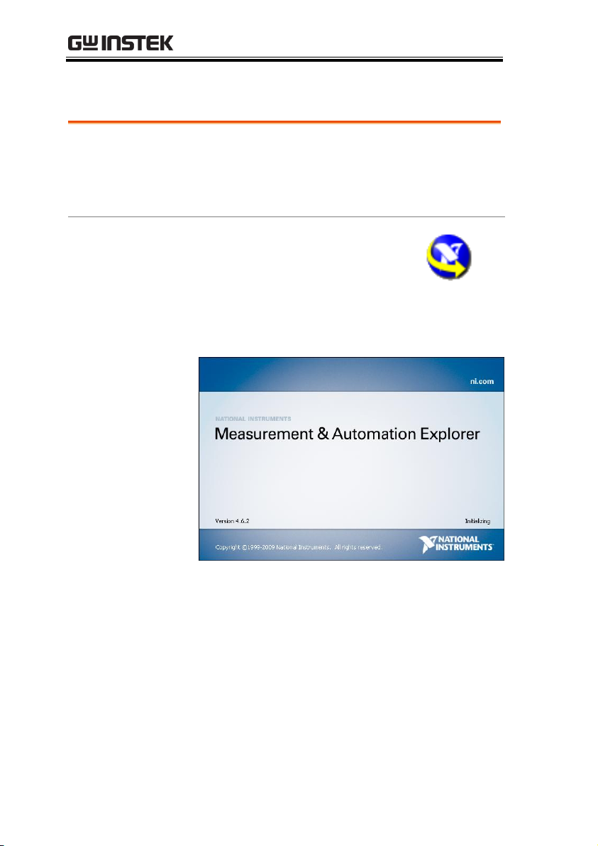
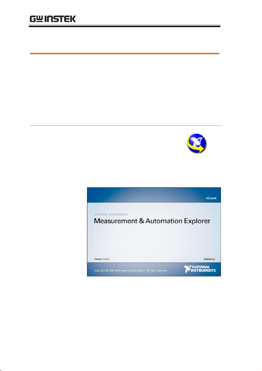
To test the socket server functionality, National
Instruments Measurement and Automation
Explorer can be used. This program is available on
the NI website, www.ni.com.
Operation
1. Start the NI Measurement and
Automation Explorer (MAX)
program. Using Windows, press:
Start>All Programs>National
Instruments>Measurement & Automation
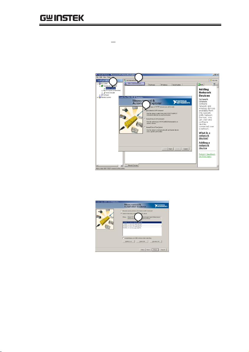
2. From the Configuration panel access;
My System>Devices and Interfaces>Network
Devices
3. Press Add New Network Device>Visa TCP/IP
Resource…
Socket Server Functionality Check
14
Page 15
INTERFACE OVERVIEW
4. Select Auto-detect of LAN Instrument from the
popup window. The GDS-2000A should be
automatically detected. If the GDS-2000A is not
detected, choose the manual option.
2
3
4
5. Select the IP address that corresponds to the
GDS-2000A and click Next.
5
15
Page 16
GDS-2000A Programming Manual
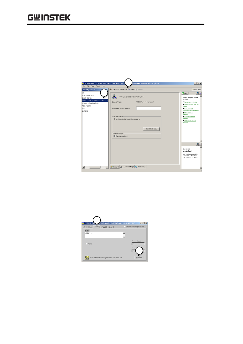
6. The GDS-2000A will now appear under
Network Devices in the Configuration Panel.
Functionality
Check
7. Click the Open Visa Test Panel to send a remote
command to the GDS-2000A.
6
7
8. Click on the viWrite tab. The *IDN? query
should already be in the buffer area.
9. Click Execute to execute the query.
8
9
16
Page 17
INTERFACE OVERVIEW
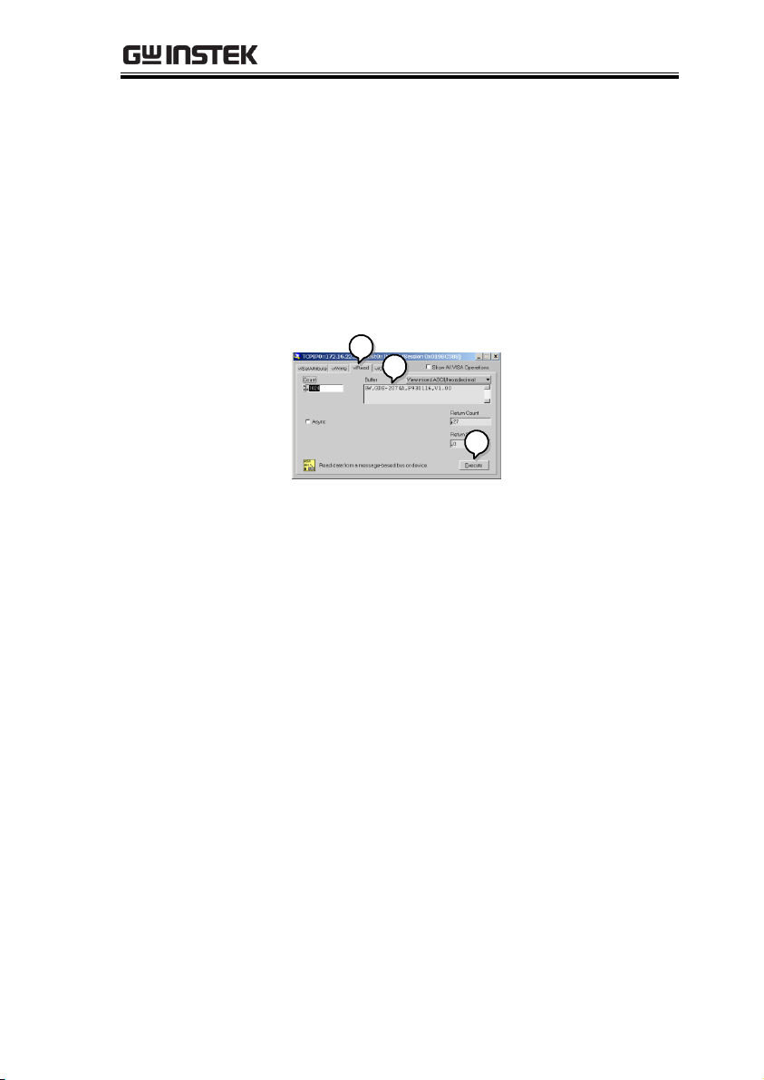
10. Click the viRead tab.
11. Click Execute to read the return parameter from
the *IDN? query.
12. The manufacturer, model number, serial
number and firmware version will be displayed
in the buffer. For example:
GW, GDS-2074A, P930116, V1.00
10
11
12
17
Page 18
GDS-2000A Programming Manual
To check that the GPIB connection is working,
National Instruments Measurement & Automation
Explorer (MAX) can be used. The following
function check is based on version 4.6.2.
For further information about National
Instruments, please see the NI website at
www.ni.com.
Operation
1. Start the NI Measurement and
Automation Explorer (MAX)
program. Using Windows, press:
Start>All Programs>National
Instruments>Measurement & Automation
2. From the Configuration panel access;
My System>Devices and Interfaces>GPIB0
GPIB Functionality Check
18
Page 19
INTERFACE OVERVIEW
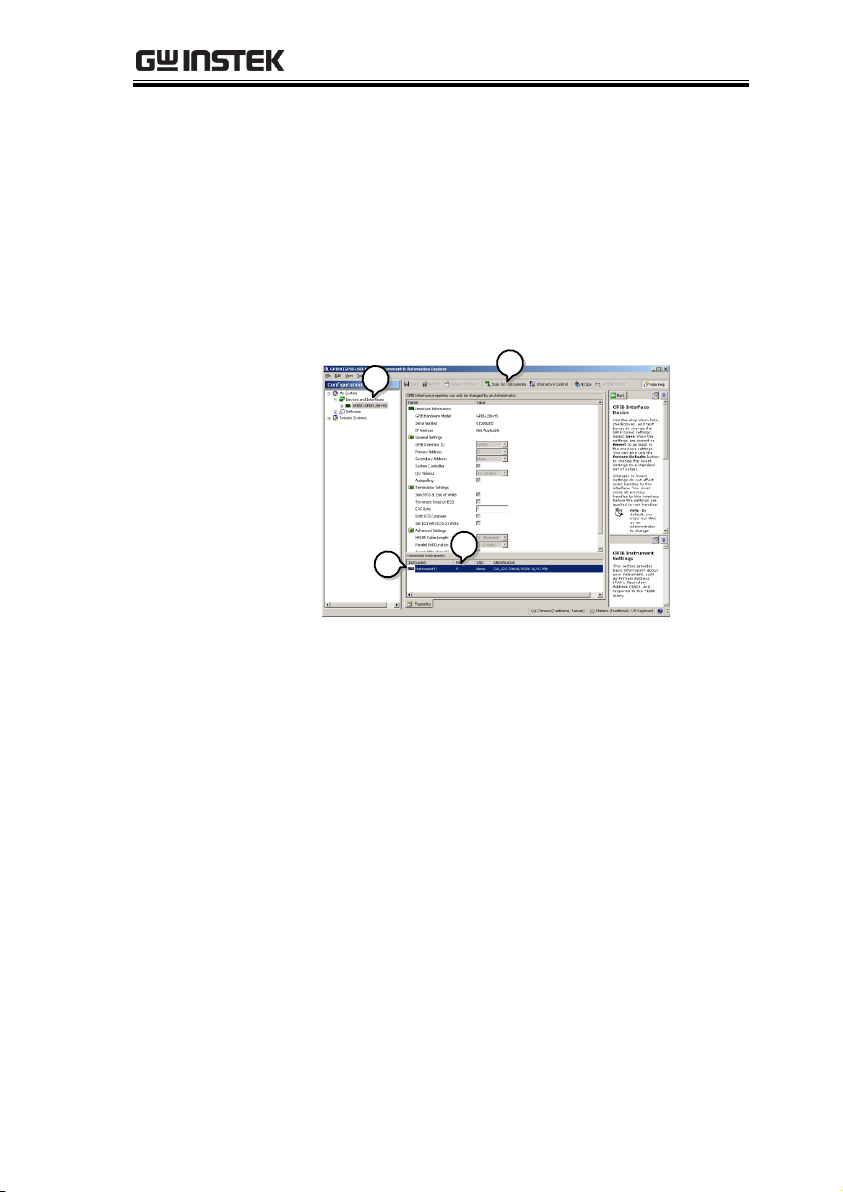
3. Press the Scan for Instruments button.
4. In the Connected Instruments panel the GDS-
2000A should be detected as Instrument 0 with
the address the same as that configured on the
GDS-2000A.
5. Double click the Instrument 0 icon.
2
3
4
5
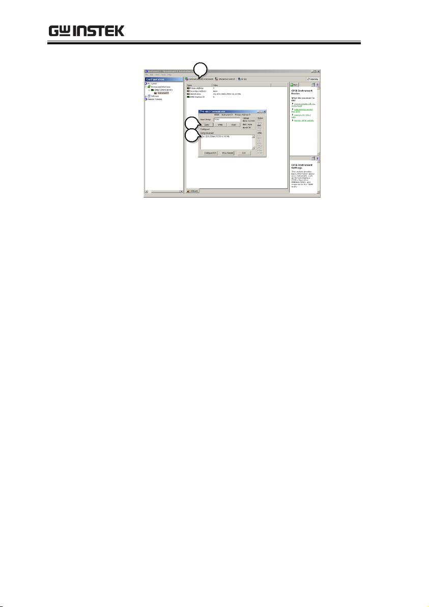
6. Click on Communicate with Instrument.
7. In the NI-488.2 Communicator window, ensure
*IND? is written in the Send String: text box.
Click on the Query button to send the *IDN?
query to the instrument.
8. The String Received text box will display the
query return:
GW, GDS-2XXXX,PXXXXXX,V1.XX
(manufacturer, model, serial number, version)
19
Page 20
GDS-2000A Programming Manual
6
7
8
9. The function check is complete.
20
Page 21

COMMAND OVERVIEW
Compatible
standard
USB CDC_ACM compatible
SCPI, 1994 (partially compatible)
Command forms
Commands and queries have two different forms,
long and short. The command syntax is written
with the short form of the command in capitals
and the remainder (long form) in lower case.
:TIMebase:SCALe?
Short
Long
Short
The commands can be written in capitals or lowercase, just so long as the short or long forms are
complete. An incomplete command will not be
recognized.
Below are examples of correctly written
commands.
LONG
:TIMebase:SCALe?
:TIMEBASE:SCALE?
:timebase:scale?
SHORT
:TIM:SCAL?
:TIM:SCAL?
COMMAND OVERVIEW
The Command overview chapter lists all GDS2000A commands in functional order as well as
alphabetical order. The command syntax section
shows you the basic syntax rules you have to
apply when using commands.
Command Syntax
21
Page 22

GDS-2000A Programming Manual
Command format
:TIMebase:SCALe <NR3>LF
1 2 3 4
1: command header
2: single space
3: parameter
4: message terminator
Parameter
Type
Description
Example
<Boolean>
boolean logic
0, 1
<NR1>
Integers
0, 1, 2, 3
<NR2>
floating point
0.1, 3.14, 8.5
<NR3>
floating point
with an exponent
4.5e-1, 8.25e+1
<NRf>
any of NR1, 2, 3
1, 1.5, 4.5e-1
Message
terminator
LF
line feed code
Note
Commands are non-case sensitive.
22
Page 23

COMMAND OVERVIEW
Common
*IDN? .......................................................................... 35
*LRN? .......................................................................... 35
*SAV ............................................................................ 37
*RCL ............................................................................ 38
*RST ............................................................................ 38
*CLS ............................................................................ 38
Acquisition
:ACQuire:AVERage ...................................................... 39
:ACQuire:MODe ......................................................... 39
:ACQuire<X>:MEMory? .............................................. 40
:ACQuire<X>:LMEMory? .............................................41
:ACQuire<X>:STATe? ...................................................41
:ACQuire:INTERpolation ............................................ 42
:ACQuire:FILTer .......................................................... 42
:ACQuire:RECOrdlength ............................................. 42
:HEADer ...................................................................... 43
Autoscale
:AUTOSet .................................................................... 44
:AUTORSET:MODe .................................................... 44
Vertical Scale
:CHANnel<X>:BWLimit .............................................. 45
:CHANnel<X>:COUPling ............................................ 46
:CHANnel<X>:DESKew .............................................. 46
:CHANnel<X>:DISPlay ............................................... 46
:CHANnel<X>:EXPand ............................................... 47
:CHANnel<X>:IMPedance? ........................................ 47
:CHANnel<X>:INVert ................................................. 48
:CHANnel<X>:POSition ............................................. 48
:CHANnel<X>:PROBe:RATio ..................................... 49
:CHANnel<X>:PROBe:TYPe ....................................... 49
:CHANnel<X>:SCALe ................................................. 49
List of Commands in Functional Order
23
Page 24

GDS-2000A Programming Manual
Math
:MATH:DISP ................................................................ 51
:MATH:TYPe ................................................................ 52
:MATH:DUAL:SOURce<X> ......................................... 52
:MATH:DUAL:OPERator ............................................. 52
:MATH:DUAL:POSition ............................................... 53
:MATH:DUAL:SCALe ................................................... 53
:MATH:FFT:SOURce .................................................. 54
:MATH:FFT:MAG ........................................................ 54
:MATH:FFT:WINDow .................................................. 54
:MATH:FFT:POSition .................................................. 55
:MATH:FFT:SCALe ...................................................... 55
:MATH:FFT:HORizontal:SCALe .................................. 56
:MATH:ADVanced:OPERator ...................................... 56
:MATH:ADVanced:SOURce ........................................ 56
:MATH:ADVanced:EDIT:SOURce<X> ........................ 57
:MATH:ADVanced:EDIT:OPERator ............................. 57
:MATH:ADVanced:POSition ....................................... 58
:MATH:ADVanced:SCALe ........................................... 58
Cursor
:CURSor:MODe ........................................................... 60
:CURSor:SOURce ......................................................... 60
:CURSor:HUNI ............................................................ 61
:CURSor:HUSE ............................................................ 61
:CURSor:VUNI ............................................................. 62
:CURSor:VUSE ............................................................. 62
:CURSor:DDT ............................................................... 62
:CURSor:H1Position .................................................... 63
:CURSor:H2Position .................................................... 63
:CURSor:HDELta ......................................................... 63
:CURSor:V1Position ..................................................... 64
:CURSor:V2Position ..................................................... 64
:CURSor:VDELta .......................................................... 64
:CURSor:XY:RECTangular:X:POSition<X> .................. 65
:CURSor:XY:RECTangular:X:DELta ............................. 65
:CURSor:XY:RECTangular:Y:POSition<X> .................. 66
24
Page 25

COMMAND OVERVIEW
:CURSor:XY:RECTangular:Y:DELta ............................ 66
:CURSor:XY:POLar:RADIUS:POSition<X> ................. 66
:CURSor:XY:POLar:RADIUS:DELta ............................ 67
:CURSor:XY:POLar:THETA:POSition<X> .................. 67
:CURSor:XY:POLar:THETA:DELta .............................. 67
:CURSor:XY:PRODuct:POSition<X> .......................... 68
:CURSor:XY:PRODuct:DELta...................................... 68
:CURSor:XY:RATio:POSition<X> ................................ 68
:CURSor:XY:RATio:DELta ........................................... 69
Display
:DISPlay:INTensity:WAVEform ................................... 69
:DISPlay:INTensity:GRATicule.................................... 70
:DISPlay:PERSistence ................................................. 70
:DISPlay:GRATicule .................................................... 70
:DISPlay:WAVEform .................................................... 72
Hardcopy
:HARDcopy:START ..................................................... 72
:HARDcopy:MODe ..................................................... 73
:HARDcopy:PRINTINKSaver ...................................... 73
:HARDcopy:SAVEINKSaver ........................................ 73
:HARDcopy:SAVEFORMat ......................................... 74
:HARDcopy:ASSIGN ................................................... 74
Measure
:MEASure:GATing ....................................................... 77
:MEASure:SOURce ..................................................... 77
:MEASure:METHod .................................................... 78
:MEASure:FALL ........................................................... 78
:MEASure:FOVShoot .................................................. 79
:MEASure:FPReshoot ................................................. 79
:MEASure:FREQuency ................................................ 80
:MEASure:NWIDth ..................................................... 80
:MEASure:PDUTy .........................................................81
:MEASure:PERiod ........................................................81
:MEASure:PWIDth ...................................................... 82
:MEASure:RISe ............................................................ 82
:MEASure:ROVShoot .................................................. 83
25
Page 26

GDS-2000A Programming Manual
:MEASure:RPReshoot .................................................. 83
:MEASure:PPULSE ....................................................... 84
:MEASure:NPULSE ...................................................... 85
:MEASure:PEDGE ........................................................ 85
:MEASure:NEDGE ....................................................... 86
:MEASure:AMPlitude ................................................... 86
:MEASure:MEAN ......................................................... 87
:MEASure:CMEan ........................................................ 87
:MEASure:HIGH .......................................................... 88
:MEASure:LOW ............................................................ 89
:MEASure:MAX ............................................................ 89
:MEASure:MIN ............................................................ 90
:MEASure:PK2PK ......................................................... 90
:MEASure:RMS ............................................................ 91
:MEASure:AREa ........................................................... 91
:MEASure:CARea ......................................................... 92
:MEASure:FRRDelay .................................................... 93
:MEASure:FRFDelay .................................................... 93
:MEASure:FFRDelay .................................................... 94
:MEASure:FFFDelay ..................................................... 94
:MEASure:LRRDelay .................................................... 95
:MEASure:LRFDelay ..................................................... 96
:MEASure:LFRDelay ..................................................... 96
:MEASure:LFFDelay ..................................................... 97
:MEASure:PHAse ......................................................... 97
Measurement
:MEASUrement:MEAS<X>:SOURCE<X> .................... 99
:MEASUrement:MEAS<X>:TYPe ............................... 100
:MEASUrement:MEAS<X>:STATE ............................ 100
:MEASUrement:MEAS<X>:VALue ............................ 101
:MEASUrement:MEAS<X>:MAXimum ..................... 102
:MEASUrement:MEAS<X>:MEAN ............................ 103
:MEASUrement:MEAS<X>:MINImum ..................... 103
:MEASUrement:MEAS<X>:STDdev .......................... 104
:MEASUrement:STATIstics:MODe ........................... 104
26
Page 27

COMMAND OVERVIEW
:MEASUrement:STATIstics:WEIghting .....................105
:MEASUrement:STATIstics .......................................105
Reference
:REF<X>:DISPlay ........................................................106
:REF<X>:TIMebase:POSition ....................................106
:REF<X>:TIMebase:SCALe ........................................107
:REF<X>:OFFSet ........................................................107
:REF<x>:SCALe ..........................................................108
Run
:RUN ..........................................................................109
Stop
:STOP .........................................................................109
Single
:SINGle .......................................................................109
Force
:FORCe .......................................................................110
Time base
:TIMebase:POSition .................................................. 111
:TIMebase:SCALe ....................................................... 111
:TIMebase:MODe ...................................................... 111
:TIMebase:WINDow:POSition ..................................112
:TIMebase:WINDow:SCALe ......................................112
Trigger
:TRIGger:FREQuency .................................................115
:TRIGger:TYPe............................................................116
:TRIGger:SOURce ......................................................116
:TRIGger:COUPle .......................................................117
:TRIGger:NREJ ...........................................................117
:TRIGger:REJect .........................................................117
:TRIGger:MODe .........................................................118
:TRIGger:HOLDoff .....................................................118
:TRIGger:LEVel ..........................................................118
:TRIGger:HLEVel .......................................................119
:TRIGger:LLEVel .........................................................120
:TRIGger:EDGe:SLOP ................................................120
:TRIGger:DELay:SLOP ...............................................121
27
Page 28

GDS-2000A Programming Manual
:TRIGger:DELay:TYPe ................................................ 121
:TRIGger:DELay:TIMe ................................................ 121
:TRIGger:DELay:EVENt .............................................. 122
:TRIGger:DELay:LEVel ............................................... 122
:TRIGger:PULSEWidth:POLarity ............................... 122
:TRIGger:RUNT:POLarity .......................................... 123
:TRIGger:RUNT:WHEn .............................................. 123
:TRIGger:RUNT:TIMe ................................................ 124
:TRIGger:RISEFall:SLOP ............................................ 124
:TRIGger:RISEFall:WHEn .......................................... 125
:TRIGger:RISEFall:TIMe ............................................ 125
:TRIGger:VIDeo:TYPe ................................................ 126
:TRIGger:VIDeo:FIELd ............................................... 126
:TRIGger:VIDeo:LINe ................................................ 127
:TRIGger:VIDeo:POLarity .......................................... 127
:TRIGger:PULSe:WHEn ............................................. 127
:TRIGger:PULSe:TIMe ............................................... 128
:TRIGger:ALTernate ................................................... 129
:TRIGger:STATe ......................................................... 129
:TRIGger:EXTERnal:PRObe:TYPe .............................. 130
:TRIGger:EXTERnal:PRObe:RATio ............................ 130
:TRIGger:BUS:TYPe ................................................... 130
:TRIGger:BUS:B1:I2C:CONDition ............................. 131
:TRIGger:BUS:B1:I2C:ADDRess:MODe .................... 132
:TRIGger:BUS:B1:I2C:ADDRess:TYPe ....................... 132
:TRIGger:BUS:B1:I2C:ADDRess:VALue .................... 133
:TRIGger:BUS:B1:I2C:ADDRess:DIRection .............. 133
:TRIGger:BUS:B1:I2C:DATa:SIZe .............................. 134
:TRIGger:BUS:B1:I2C:DATa:VALue ........................... 134
:TRIGger:BUS:B1:UART:CONDition ......................... 135
:TRIGger:BUS:B1:UART:RX:DATa:SIZe .................... 136
:TRIGger:BUS:B1:UART:RX:DATa:VALue ................. 136
:TRIGger:BUS:B1:UART:TX:DATa:SIZe .................... 137
:TRIGger:BUS:B1:UART:TX:DATa:VALue ................. 137
:TRIGger:BUS:B1:SPI:CONDition ............................. 138
28
Page 29

COMMAND OVERVIEW
:TRIGger:BUS:B1:SPI:DATa:SIZe ..............................139
:TRIGger:BUS:B1:SPI:DATa:MISO:VALue ................139
:TRIGger:BUS:B1:SPI:DATa:MOSI:VALue ................140
:TRIGger:BUS:B1:PARallel:VALue .............................141
:TRIGger:LOGic:INPut:CLOCK:SOURce ...................141
:TRIGger:LOGic:PATtern ...........................................142
:TRIGger:LOGic:PATtern:INPut:D<X> ......................142
:TRIGger:LOGic:PATtern:DELTatime ........................143
:TRIGger:LOGic:PATtern:WHEn ...............................143
System
commands
:SYSTem:LOCK ..........................................................146
:SYSTem:ERRor ..........................................................146
Save/Recall
:RECAll:SETUp ...........................................................147
:RECAll:WAVEform ....................................................148
:SAVe:IMAGe .............................................................148
:SAVe:IMAGe:FILEFormat .........................................149
:SAVe:IMAGe:INKSaver .............................................149
:SAVe:SETUp ..............................................................149
:SAVe:WAVEform .......................................................150
:SAVe:WAVEform:FILEFormat ..................................151
Ethernet
Commands
:ETHERnet:DHCP ......................................................153
Time Commands
:DATe .........................................................................154
Bus Decode
Commands
:BUS1 .........................................................................155
:BUS1:STATE .............................................................156
:BUS1:TYPe ................................................................156
:BUS1:I2C:ADDRess:RWINClude ..............................157
:BUS1:I2C:SCLK:SOURce ..........................................157
:BUS1:I2C:SDA:SOURce ............................................157
:BUS1:UART:BITRate .................................................158
:BUS1:UART:PARIty ...................................................159
:BUS1:UART:PACKEt .................................................159
:BUS1:UART:EOFPAcket ...........................................159
29
Page 30

GDS-2000A Programming Manual
:BUS1:UART:TX:SOURce .......................................... 160
:BUS1:UART:RX:SOURce .......................................... 160
:BUS1:SPI:SCLK:POLARity ........................................ 161
:BUS1:SPI:SS:POLARity ............................................. 161
:BUS1:SPI:WORDSize ............................................... 161
:BUS1:SPI:BITORder ................................................. 162
:BUS1:SPI:SCLK:SOURce .......................................... 162
:BUS1:SPI:SS:SOURce ............................................... 162
:BUS1:SPI:MOSI:SOURce ......................................... 163
:BUS1:SPI:MISO:SOURce ......................................... 163
:BUS1:PARallel:BIT<X>:SOURce ............................... 163
:BUS1:PARallel:CLOCK:EDGE ................................... 164
:BUS1:PARallel:CLOCK:SOURce ............................... 164
:BUS1:PARallel:WIDth ............................................... 165
:BUS1:DISplay:FORMAt ............................................ 165
Mark Commands
:MARK ........................................................................ 166
:MARK:CREATE.......................................................... 166
:MARK:DELEte ........................................................... 167
Search
Commands
:SEARCH:COPY ......................................................... 169
:SEARCH:STATE ........................................................ 169
:SEARCH:TOTAL ....................................................... 170
:SEARCH:TRIGger:TYPe ............................................ 170
:SEARCH:TRIGger:SOURce ....................................... 170
:SEARCH:TRIGger:EDGE:SLOP ................................ 171
:SEARCH:TRIGger:LEVel ........................................... 171
:SEARCH:TRIGger:HLEVel ........................................ 172
:SEARCH:TRIGger:LLEVel ......................................... 172
:SEARCH:TRIGger:PULSEWidth:POLarity ................ 173
:SEARCH:TRIGger:RUNT:POLarity ........................... 173
:SEARCH:TRIGger:RISEFall:SLOP ............................ 174
:SEARCH:TRIGger:PULSe:WHEn .............................. 174
:SEARCH:TRIGger:PULSe:TIMe ................................ 175
:SEARCH:TRIGger:RUNT:WHEn .............................. 175
30
Page 31

COMMAND OVERVIEW
:SEARCH:TRIGger:RUNT:TIMe .................................176
:SEARCH:TRIGger:RISEFall:WHEn ...........................176
:SEARCH:TRIGger:RISEFall:TIMe .............................177
:SEARCH:TRIGger:LOGic:INPut:CLOCK:SOURce ...177
:SEARCH:TRIGger:LOGic:PATtern ............................178
:SEARCH:TRIGger:LOGic:PATtern:INPut:D .............178
:SEARCH:TRIGger:LOGic:PATtern:DELTatime ........179
:SEARCH:TRIGger:LOGic:PATtern:WHEn ................179
:SEARCH:TRIGger:BUS:TYPe ....................................180
:SEARCH:TRIGger:BUS:B1:I2C:CONDition ..............181
:SEARCH:TRIGger:BUS:B1:I2C:ADDRess:MODe ....181
:SEARCH:TRIGger:BUS:B1:I2C:ADDRess:TYPe .......182
:SEARCH:TRIGger:BUS:B1:I2C:ADDRess:VALue .....183
:SEARCH:TRIGger:BUS:B1:I2C:ADDRess:DIRection183
:SEARCH:TRIGger:BUS:B1:I2C:DATa:SIZe ...............184
:SEARCH:TRIGger:BUS:B1:I2C:DATa:VALue ............184
:SEARCH:TRIGger:BUS:B1:UART:CONDition ..........185
:SEARCH:TRIGger:BUS:B1:UART:RX:DATa:SIZe .....186
:SEARCH:TRIGger:BUS:B1:UART:RX:DATa:VALue ..187
:SEARCH:TRIGger:BUS:B1:UART:TX:DATa:SIZe .....187
:SEARCH:TRIGger:BUS:B1:UART:TX:DATa:VALue ..188
:SEARCH:TRIGger:BUS:B1:SPI:CONDition ..............189
:SEARCH:TRIGger:BUS:B1:SPI:DATa:SIZe ...............189
:SEARCH:TRIGger:BUS:B1:SPI:DATa:MISO:VALue .190
:SEARCH:TRIGger:BUS:B1:SPI:DATa:MOSI:VALue .191
:SEARCH:TRIGger:BUS:B1:PARallel:VALue ..............191
Digital
Commands
:D<X>:DISPlay ...........................................................193
:D<X>:POSition .........................................................193
:DISPlay:DIGital:HEIght ............................................193
:DIGital:GROUP<X>:THREshold ..............................194
:DIGital:ANAlog:A<X>:DISPlay .................................195
:DIGital:ANAlog:A<X>:RATio ....................................195
:D<x>:MEMory ...........................................................195
:D<x>:LMEMory .........................................................196
31
Page 32

GDS-2000A Programming Manual
:DIGital:MEMory ....................................................... 197
:DIGital:LMEMory ..................................................... 198
Label Commands
:CHANnel<X>:LABel .................................................. 199
:CHANnel<X>:LABel:DISPlay .................................... 200
:REF<X>:LABel ........................................................... 200
:REF<X>:LABel:DISPlay ............................................. 201
:BUS1:LABel ............................................................... 202
:BUS1:LABel:DISPlay ................................................. 202
:D<X>:LABel............................................................... 203
:D<X>:LABel:DISPlay ................................................. 204
:DIGital:ANAlog:A<X>:LABel .................................... 204
:DIGital:ANAlog:A<X>:LABel:DISPlay ....................... 205
:SET<X>:LABel ........................................................... 206
Utility
Commands
:BUZZER .................................................................... 207
32
Page 33

COMMAND DETAILS
Common Commands ............................... 35
Acquisition Commands ............................ 39
Autoscale Commands .............................. 44
Vertical Commands .................................. 45
Math Commands ..................................... 51
Cursor Commands ................................... 59
Display Commands .................................. 69
Hardcopy Commands .............................. 72
Measure Commands ................................ 76
Measurement Commands ........................ 99
Reference Commands ............................. 106
Run Command ........................................ 109
Stop Command ....................................... 109
Single Command ..................................... 109
Force Command ...................................... 110
Timebase Commands .............................. 111
Trigger Commands .................................. 114
System Commands ................................. 146
Save/Recall Commands .......................... 147
Ethernet Commands ............................... 153
Time Commands ..................................... 154
Bus Decode Commands .......................... 155
Mark Commands ..................................... 166
Search Commands .................................. 168
COMMAND DETAILS
The Command details chapter shows the detailed
syntax, equivalent panel operation, and example
for each command. For the list of all commands,
see page23.
33
Page 34

GDS-2000A Programming Manual
Digital Commands ................................. 192
Label Commands ................................... 199
Utility Commands .................................. 207
34
Page 35

COMMAND DETAILS
*IDN? .......................................................................... 35
*LRN? .......................................................................... 35
*SAV ............................................................................ 37
*RCL ............................................................................ 38
*RST ............................................................................ 38
*CLS ............................................................................ 38
*IDN?
Query
Description
Returns the manufacturer, model, serial number
and version number of the unit.
Syntax
*IDN?
Example
*IDN?
GW,GDS-2064A,P930116,V0.82b
*LRN?
Query
Description
Returns the oscilloscope settings as a data string.
Syntax
*LRN?
Example
*LRN?
:DISPlay:WAVEform VECTOR;PERSistence 2.400E01;INTensity:WAVEform 50;INTensity:GRATicule 50;GRATicule
FULL;:CHANnel CH1:DISPlay ON;BWLimit FULL;COUPling
DC;INVert OFF;POSition -8.800E-02;PROBe:RATio
1.000e+00;PROBe:TYPe VOLTAGE;SCALe 5.000E-02;IMPedance
1E+6;EXPand GROUND;:CHANnel CH2:DISPlay OFF;BWLimit
FULL;COUPling DC;INVert OFF;POSition 3.120E-03;PROBe:RATio
1.000e+00;PROBe:TYPe VOLTAGE;SCALe 2.000E-03;IMPedance
1E+6;EXPand GROUND;:MATH:TYPe DUAL;DISP
OFF;DUAL:SOURce1 CH1;SOURce2 CH2;OPERator PLUS;POSition
0.000E+00;SCALe 2.000E-03;FFT:SOURce CH1;MAG DB;WINDow
HANNING;POSition
0.000E+00;SCALe ?;MATH:ADVanced:OPERator
DIFF;ADVanced:SOURce CH1;ADVanced:EDIT:SOURce1
Common Commands
35
Page 36

GDS-2000A Programming Manual
CH1;ADVanced:EDIT:SOURce2 CH2;ADVanced:EDIT:OPERator
PLUS;ADVanced:POSition
0.000E+00;ADVanced:SCALe ?;:MEASure:GATing SCREEN;SOURce1
CH1;SOURce2 CH2;:TIMebase:MODe MAIN;SCALe 2.000E04;POSition 0.000E+00;WINDow:SCALe 1.000E-05;:ACQuire:MODe
SAMPE;AVERage 4;:CURSor:SOURce
CH1;MODe ;H1Position ;H2Position ;V1Position ;V2Position ---- -
--- ---- ---- ;:HARDcopy:MODe SAVE;PRINTINKSaver
ON;SAVEINKSaver OFF;SAVEFORMat BMP;ASSIGN
IMAGE;:TRIGger:FREQuency 1.000E+03;TYPe EDGE;SOURce
CH1;COUPle DC;NREJ OFF;REJect OFF;MODe AUTO;HOLDoff
1.000e-08;LEVelH 8.800E-02;LEVelL ?;EDGe:SLOP RISE;DELay:TYPe
TIME;DELay:TIME 0.000;DELay:EVENt 1;DELay:LEVel ?;DELay:SLOP
RISE;PULSEWidth:POLarity POSITIVE;RUNT:POLarity
POSITIVE;RUNT:WHEn THAN;RUNT:TIMe 0.000;RISEFall:SLOP
RISE;RISEFall:WHEn THAN;RISEFall:TIMe 0.000;VIDeo:TYPe
NTSC;VIDeo:FIELd FIELD1;VIDeo:LINe 1;VIDeo:POLarity
NEGATIVE;PULSe:WHEn THAN;PULSe:TIME 0.000;ALTernate
OFF;EXTERnal:PRObe:TYPe VOLTAGE;EXTERnal:PRObe:RATio
1.000e+00;:TRIGGER:LOGIC:INPut:CLOCK:EDGe RISE;SOURce
NONE;:TRIGGER:LOGIC:PATTERM:INPUT::TRIGGER:LOGIC:PATT
ERM:WHEN TRUE;:TRIGGER:LOGIC:PATTERM:DELTATIME 1.000e08;:TRIGger:BUS:TYPe PARALLEL;:TRIGger:BUS:B1:PARallel:VALue
XXXXXXXX;:B1:I2C:ADDRess:VALue XXXXXXX;:CONDition
MISSACK;:ADDRess:DIRection WRITE;:DATa:SIZe 1;:DATa:VALue
XXXXXXXX;:UART:CONDition TXDATA;:RX:DATa:SIZe
1;:RX:DATa:VALue XXXXXXXX;:TX:DATa:SIZe 1;:TX:DATa:VALue
XXXXXXXX;:SPI:CONDition SS;:DATa:SIZe 1;:DATa:MISO:VALue
XXXX;:DATa:MOSI:VALue XXXX;:REF1:DISPlay
OFF;TIMebase:POSition 0.000E+00;SCALe 2.000E-04;OFFSet
0.000E+00;SCALe 5.000E-01;:REF2:DISPlay OFF;TIMebase:POSition
0.000E+00;SCALe 2.000E-04;OFFSet 0.000E+00;SCALe 5.000E01;:REF3:DISPlay OFF;TIMebase:POSition 0.000E+00;SCALe
2.000E-04;OFFSet 0.000E+00;SCALe 5.000E-01;:REF4:DISPlay
OFF;TIMebase:POSition 0.000E+00;SCALe 2.000E-04;OFFSet
0.000E+00;SCALe 5.000E-01;:DISPlay:DIGital:HEIght
SMALL;:BUS1:TYPe PARALLEL;:BUS1:DISplay:FORMAt
HEXADECIMAL;:BUS1:PARallel:WIDth 8;:BIT0:SOUrce
D0;:BIT1:SOUrce D1;:BIT2:SOUrce D2;:BIT3:SOUrce
D3;:BIT4:SOUrce D4;:BIT5:SOUrce D5;:BIT6:SOUrce
D6;:BIT7:SOUrce D7;:CLOCK:EDGE RISE;:CLOCK:SOUrce
D0;:BUS1:STATE OFF;:I2C:ADDRess:RWINClude
ON;:I2C:ADDRess:MODE 7BIT;:I2C:SCLK:SOURCE
D0;:I2C:SDA:SOURCE D1;UART:BITRate 14;:UART:PARIty
0;:UART:PACKEt 0;:UART:EOFPAcket 0;:UART:TX:SOURCE
D0;:UART:RX:SOURCE D1;:SPI:SCLK:POLARity
RISE;:SPI:SS:POLARity LOW;:SPI:WORDSize 4;:SPI:BITORder
0;:SPI:SCLK:SOURCE D0;:SPI:SS:SOURCE D1;:SPI:MOSI:SOURCE
D2;:SPI:MISO:SOURCE D3;:SEARCH:STATE OFF;:TOTAL
0;:TRIGger:TYPe EDGE;:TRIGger:SOUrce
CH1;:TRIGger:EDGE:SLOP RISE;:TRIGger:LEVel
36
Page 37

COMMAND DETAILS
0.00V;:TRIGger:HLEVel 0.00V;:TRIGger:LLEVel
0.00V;:TRIGger:PULSEWidth:POLarity
POSITIVE;:TRIGger:RUNT:POLarity
POSITIVE;:TRIGger:RISEFall:SLOP RISE;:TRIGger:PULSe:WHEn
THAN;:TRIGger:PULSe:TIMe 8.000e-08;:TRIGger:RUNT:WHEn
THAN;:TRIGger:RUNT:TIMe 8.000e-08;:TRIGger:RISEFall:WHEn
THAN;:TRIGger:RISEFall:TIMe 8.000e08;:SEARCH:TRIGGER:LOGIC:INPut:CLOCK:EDGe RISE;SOURce
NONE;:SEARCH:TRIGGER:LOGIC:PATTERM:INPUT::SEARCH:TRIG
GER:LOGIC:PATTERM:WHEN
TRUE;:TRIGGER:LOGIC:PATTERM:DELTATIME 1.000e08;:TRIGger:BUS:TYPe PARALLEL;:TRIGger:BUS:B1:PARallel:VALue
XXXXXXXX;:B1:I2C:ADDRess:VALue XXXXXXX;:CONDition
START;:ADDRess:DIRection WRITE;:DATa:SIZe 1;:DATa:VALue
XXXXXXXX;:UART:CONDition TXSTART;:RX:DATa:SIZe
1;:RX:DATa:VALue XXXXXXXX;:TX:DATa:SIZe 1;:TX:DATa:VALue
XXXXXXXX;:SPI:CONDition SS;:DATa:SIZe 1;:DATa:MISO:VALue
XXXX;:DATa:MOSI:VALue
XXXX;:CHANnel1:LABel ;:CHANnel2:LABel ;:CHANnel3:LABel ;:CH
ANnel4:LABel ;:REF1:LABel ;:REF2:LABel ;:REF3:LABel ;:REF4:LABel
;:SET1:LABel ;:SET2:LABel ;:SET3:LABel ;:SET4:LABel ;:SET5:LABel ;:
SET6:LABel ;:SET7:LABel ;:SET8:LABel ;:SET9:LABel ;:SET10:LABel ;:
SET11:LABel ;:SET12:LABel ;:SET13:LABel ;:SET14:LABel ;:SET15:LA
Bel ;:SET16:LABel ;:SET17:LABel ;:SET18:LABel ;:SET19:LABel ;:SET2
0:LABel ;:BUS1:LABel ;:D0:LABel ;:D1:LABel ;:D2:LABel ;:D3:LABel ;:
D4:LABel ;:D5:LABel ;:D6:LABel ;:D7:LABel ;:D8:LABel ;:D9:LABel ;:
D10:LABel ;:D11:LABel ;:D12:LABel ;:D13:LABel ;:D14:LABel ;:D15:L
ABel ;:CHANnel1:LABel:DISPlay OFF;:CHANnel2:LABel:DISPlay
OFF;:CHANnel3:LABel:DISPlay OFF;:CHANnel4:LABel:DISPlay
OFF;:REF0:LABel:DISPlay OFF;:REF1:LABel:DISPlay
OFF;:REF2:LABel:DISPlay OFF;:REF3:LABel:DISPlay
OFF;:BUS1:LABel:DISPlay OFF;:D0:LABel:DISPlay
OFF;:D1:LABel:DISPlay OFF;:D2:LABel:DISPlay
OFF;:D3:LABel:DISPlay OFF;:D4:LABel:DISPlay
OFF;:D5:LABel:DISPlay OFF;:D6:LABel:DISPlay
OFF;:D7:LABel:DISPlay OFF;:D8:LABel:DISPlay
OFF;:D9:LABel:DISPlay OFF;:D10:LABel:DISPlay
OFF;:D11:LABel:DISPlay OFF;:D12:LABel:DISPlay
OFF;:D13:LABel:DISPlay OFF;:D14:LABel:DISPlay
OFF;:D15:LABel:DISPlay OFF;:BUZZER OFF
*SAV
Set
Description
Saves the current panel settings to the selected
memory number.
Syntax
*SAV {1 | 2 | 3 |…. | 20}
37
Page 38

GDS-2000A Programming Manual
Example
*SAV 1
Saves the current panel settings to Set 1..
*RCL
Set
Description
Recalls a set of panel settings.
Syntax
*RCL {1 | 2 | 3 |…. | 20}
Example
*RCL 1
Recalls the selected setup from Set 1.
*RST
Set
Description
Resets the GDS-2000A (recalls the default panel
settings).
Syntax
*RST
*CLS
Set
Description
Clears the error queue.
Syntax
*CLS
38
Page 39

COMMAND DETAILS
:ACQuire:AVERage ...................................................... 39
:ACQuire:MODe ......................................................... 39
:ACQuire<X>:MEMory? .............................................. 40
:ACQuire<X>:LMEMory? .............................................41
:ACQuire<X>:STATe? ...................................................41
:ACQuire:INTERpolation ............................................ 42
:ACQuire:FILTer .......................................................... 42
:ACQuire:RECOrdlength ............................................. 42
:HEADer ...................................................................... 43
:ACQuire:AVERage
Set
Query
Description
Selects or returns the number of waveform
acquisitions that are averaged in the average
acquisition mode.
Syntax
:ACQuire:AVERage {<NR1>| ?}
Related
Commands
:ACQuire:MODe
Parameter
<NR1>
2, 4, 8 ,16, 32, 64, 128, 256
Note
Before using this command, select the average
acquisition mode. See the example below.
Example
:ACQuire:MODe AVERage
:ACQuire:AVERage 2
Selects the average acquisition mode, and sets the
average number to 2.
:ACQuire:MODe
Set
Query
Description
Selects or returns the acquisition mode.
Syntax
:ACQuire:MODe {SAMPle | PDETect | AVERage | ?}
Acquisition Commands
39
Page 40

GDS-2000A Programming Manual
Related
Commands
:ACQuire:AVERage
Parameter
SAMPle
Sample mode sampling
PDETect
Peak detect sampling
AVERage
Average sampling mode
Example
:ACQuire:MODe PDETect
Sets the sampling mode to peak detection.
:ACQuire<X>:MEMory?
Query
Description
Returns the data in acquisition memory for the
selected channel as a header + raw data.
Syntax
:ACQuire<X>:MEMory?
Related
Commands
ACQuire:RECOrdlength
:HEADer
Parameter
<X>
Channel number (1 to 4)
Example
:ACQuire1:MEMory?
Format,2.0A;Memory
Length,5000;IntpDistance,0;Trigger
Address,2499;Trigger Level,9.400E02;Source,CH1;Vertical Units,V;Vertical Units
Div,0;Vertical Units Extend Div,13;Label,;Probe
Type,0;Probe,1.000e+00;Vertical Scale,5.000e02;Vertical Position,-9.400e-02;Horizontal
Units,S;Horizontal Scale,2.000E-04;Horizontal
Position,0.000E+00;Horizontal Mode,Main;SincET
Mode,Real Time;Sampling Period,4.000e07;Horizontal Old Scale,2.000E-04;Horizontal Old
Position,0.000E+00;Firmware,V0.99.03;Time,19Sep-12 10:04:48;Waveform Data; #510000 <Raw
Data> <LF>
40
Page 41

COMMAND DETAILS
:ACQuire<X>:LMEMory?
Query
Description
Returns the data in acquisition memory for the
selected channel as a header + raw data. This is
the equivalent to the Detail LM format.
Syntax
:ACQuire<X>:LMEMory?
Related
Commands
:ACQuire:RECOrdlength
:HEADer
Parameter
<X>
Channel number (1 to 4)
Example
:ACQuire1:LMEMory?
Format,2.0A,Memory
Length,1000000,IntpDistance,0,Trigger
Address,2499,Trigger Level,9.400E02,Source,CH1,Vertical Units,V,Vertical Units
Div,0,Vertical Units Extend Div,13,Label,;Probe
Type,0,Probe,1.000E+00,Vertical Scale,5.000E-02,Vertical
Position,-9.400E-02,Horizontal Units,S,Horizontal
Scale,2.000E-04,Horizontal
Position,0.000E+00,Horizontal Mode,Main,SincET
Mode,Real Time,Sampling Period,2.000E-09,Horizontal
Old Scale,2.000E-04,Horizontal Old
Position,0.000E+00,Firmware,V0.99.03,Time,19-Sep-12
10:40:10,Waveform Data; #72000000 <Raw Data> <LF>
:ACQuire<X>:STATe?
Query
Description
Returns the status of waveform data.
Syntax
:ACQuire<X>:STATe?
Parameter
<X>
Channel number (1 to 4)
Return parameter
0
Raw data is not ready
1
Raw data is ready
41
Page 42

GDS-2000A Programming Manual
Example
:ACQuire1:STATe?
0
Returns 0. The channel 1’s raw data is not ready.
Note: If the oscilloscope changes the acquisition status
from STOP to RUN, the status will be reset as zero.
:ACQuire:INTERpolation
Set
Query
Description
Selects or returns the interpolation mode.
Syntax
:ACQuire:INTERpolation {ET | SINC | ?}
Parameter/Return
parameter
ET
Set the Equivalent Time interpolation.
SINC
Sets to SIN(X)/X interpolation
Example
:ACQuire:INTERpolation ET
Sets the scope to ET interpolation.
:ACQuire:FILTer
Set
Query
Description
Sets the normalized cut-off frequency to the
nearest set. [0.02 : 0.02~0.98]
Syntax
:ACQuire:FILTer {OFF | <NR3> | ?}
Parameter/Return
parameter
OFF
Turns the digital filter off.
<NR3>
0.02,0.04~0.98.
Example
:ACQuire:FILTer OFF
Turns the digital filter off.
:ACQuire:RECOrdlength
Set
Query
Description
Sets or queries the record length. Please see the
user manual for full details.
Syntax
:ACQuire:RECOrdlength {AUTo | SHORT | ?}
Parameter/Return
AUTo
Auto record length.
42
Page 43

COMMAND DETAILS
parameter
SHORT
Short record length.
Example
:ACQuire:RECOrdlength?
AUTO
The record length is currently set to AUTO.
:HEADer
Set
Query
Description
Configures whether the :ACQuire:MEM
or :ACQuire:LMEM return data will contain
header information or not. It is set to ON by
default.
Syntax
:HEADer {OFF | ON | ?}
Related
Commands
:ACQuire<X>:MEMory?
:ACQuire<X>:LMEMory?
Parameter
<X>
Channel number (1 to 4)
ON
Add header information.
OFF
Don’t add header information.
Return parameter
Returns the configuration (ON, OFF) for the selected
channel.
Example
:HEADer ON
43
Page 44

GDS-2000A Programming Manual
:AUTOSet ..................................................................... 44
:AUTORSET:MODe ..................................................... 44
:AUTOSet
Set
Description
Runs the Autoset function to automatically
configure the horizontal scale, vertical scale, and
trigger according to the input signal.
Syntax
:AUTOSet
:AUTORSET:MODe
Set
Query
Description
Sets the Autoset mode or queries its state.
Syntax
:AUTORSET:MODe {FITScreen | ACPriority | ?}
Related
Commands
:AUTOSet
Parameter/Return
parameter
FITScreen
Fit Screen mode
ACPriority
AC priority mode
Example
:AUTORSET?
FITSCREEN
Autoscale Commands
44
Page 45

COMMAND DETAILS
:CHANnel<X>:BWLimit .............................................. 45
:CHANnel<X>:COUPling ............................................ 46
:CHANnel<X>:DESKew .............................................. 46
:CHANnel<X>:DISPlay ............................................... 46
:CHANnel<X>:EXPand ............................................... 47
:CHANnel<X>:IMPedance? ........................................ 47
:CHANnel<X>:INVert ................................................. 48
:CHANnel<X>:POSition ............................................. 48
:CHANnel<X>:PROBe:RATio ..................................... 49
:CHANnel<X>:PROBe:TYPe ....................................... 49
:CHANnel<X>:SCALe ................................................. 49
:CHANnel<X>:BWLimit
Set
Query
Description
Sets or returns the bandwidth limit on/off.
Syntax
:CHANnel<X>:BWLimit {FULL | <NR3> | ?}
Parameter
<X>
Channel 1,2,3,4
FULL
Full bandwidth
<NR3>
Sets the bandwidth limit to a pre-defined
bandwidth.
200E+6: 200MHz
100E+6: 100MHz
20E+6: 20MHz
Return Parameter
<NR3>
Returns the bandwidth.
Full
Full bandwidth
Example
:CHANnel1:BWLimit 2.000E+07
Sets the channel 1 bandwidth 20MHz
Vertical Commands
45
Page 46

GDS-2000A Programming Manual
:CHANnel<X>:COUPling
Set
Query
Description
Selects or returns the coupling mode.
Syntax
CHANnel<X>:COUPling {AC | DC | GND | ?}
Parameter
<X>
Channel 1,2,3,4
AC
AC coupling
DC
DC coupling
GND
Ground coupling
Return parameter
Returns the coupling mode.
Example
:CHANnel1:COUPling DC
Sets the coupling to DC for Channel 1.
:CHANnel<X>:DESKew
Set
Query
Description
Sets the deskew time in seconds.
Syntax
:CHANnel<X>:DESKew { <NR3> | ?}
Parameter
<X>
Channel 1,2,3,4
<NR3>
Deskew time:
-5.00E -11 to 5.00E-11
-50ns to 50 ns.
Return parameter
<NR3>
Returns the deskew time.
Example
:CHANnel1:DESKew 1.300E-9
Sets the deskew time to 1.3 nano seconds.
:CHANnel<X>:DISPlay
Set
Query
Description
Turns a channel on/off or returns its status.
Syntax
:CHANnel<X>:DISPlay {OFF | ON | ?}
Parameter
<X>
Channel 1,2,3,4
OFF
Channel off
ON
Channel on
46
Page 47

COMMAND DETAILS
Return Parameter
ON
Channel is on.
OFF
Channel is off
Example
:CHANnel1:DISPlay ON
Turns on Channel 1
:CHANnel<X>:EXPand
Set
Query
Description
Sets Expand By Ground or Expand By Center for a
channel or queries its status.
Syntax
:CHANnel<X>:EXPand {GND | CENTer | ?}
Parameter
<X>
Channel 1,2,3,4
GND
Ground
CENTer
Center
Return parameter
GND
Expand By Ground
CENTER
Expand By Center
Example
:CHANnel1:EXPand GND
Sets Channel 1 to Expand By Ground.
:CHANnel<X>:IMPedance?
Query
Description
Returns the impedance of the oscilloscope.
Syntax
:CHANnel<X>:IMPedance?
Parameter
<x>
Channel
1/2/3/4
CH1/2/3/4
Return parameter
<NR3>
Returns the impedance value.
Example
:CHANnel1:IMPedance?
1.000000E+06
The impedance is 1M ohms.
47
Page 48

GDS-2000A Programming Manual
:CHANnel<X>:INVert
Set
Query
Description
Inverts a channel or returns its status.
Syntax
:CHANnel<X>:INVert {OFF | ON | ?}
Parameter
<X>
Channel 1, 2, 3, 4
OFF
Invert off
ON
Invert on
Return parameter
ON
Invert on
OFF
Invert off
Example
:CHANnel1:INVert ON
Inverts Channel 1
:CHANnel<X>:POSition
Set
Query
Description
Sets or returns the position level for a channel.
Note
The vertical position will only be set to closest
allowed value. The position level range depends
on the vertical scale.
The scale must first be set before the position can
be set.
Syntax
:CHANnel<X>:POSition { <NRf> | ?}
Parameter
<X>
Channel 1, 2, 3, 4
<NRf>
Position. Range depends on the vertical
scale.
Return parameter
<NR3>
Returns the position value.
Example 1
:CHANnel1:POSition 2.4E–3
Sets the Channel 1 position to 2.4mV/mA
Example 2
:CHANnel1:POSition?
2.4E-3
Returns 2.4mV as the vertical position.
48
Page 49

COMMAND DETAILS
:CHANnel<X>:PROBe:RATio
Set
Query
Description
Sets or returns the probe attenuation factor.
Syntax
:CHANnel<X>:PROBe:RATio { <NRf> | ?}
Related
Commands
:CHANnel<X>:PROBe:TYPe
Parameter
<X>
Channel 1, 2, 3, 4
<NRf>
Probe attenuation factor.
Return parameter
<NR3>
Returns the probe factor.
Example
:CHANnel1:PROBe:RATio 1.00E+0
Sets the Channel 1 probe attenuation factor to 1x
:CHANnel<X>:PROBe:TYPe
Set
Query
Description
Sets or returns the probe type (voltage/current).
Syntax
:CHANnel<X>:PROBe:TYPe { VOLTage | CURRent | ?}
Related
Commands
:CHANnel<X>:PROBe:RATio
Parameter
<X>
Channel 1, 2, 3, 4
VOLTage
Voltage
CURRent
Current
Return parameter
Returns the probe type.
Example
:CHANnel1:PROBe:TYPe VOLTage
Sets the Channel 1 probe type to voltage.
:CHANnel<X>:SCALe
Set
Query
Description
Sets or returns the vertical scale. The scale depends
on the probe attenuation factor.
Note the probe attenuation factor should be set
before the scale.
49
Page 50

GDS-2000A Programming Manual
Syntax
:CHANnel<X>:SCALe { <NRf> | ?}
Parameter
<X>
Channel 1, 2, 3, 4
<NRf>
Vertical scale:
2e–3 to 1e+1
2mV to 10V (Probe x1)
Return parameter
<NR3>
Returns the vertical scale in volts or amps.
Example
:CHANnel1:SCAle 2.00E–2
Sets the Channel 1 vertical scale to 20mV/div
50
Page 51

COMMAND DETAILS
:MATH:DISP ................................................................51
:MATH:TYPe ............................................................... 52
:MATH:DUAL:SOURce<X> ........................................ 52
:MATH:DUAL:OPERator ............................................ 52
:MATH:DUAL:POSition .............................................. 53
:MATH:DUAL:SCALe .................................................. 53
:MATH:FFT:SOURce ................................................. 54
:MATH:FFT:MAG ........................................................ 54
:MATH:FFT:WINDow ................................................. 54
:MATH:FFT:POSition ................................................. 55
:MATH:FFT:SCALe ...................................................... 55
:MATH:FFT:HORizontal:SCALe ................................. 56
:MATH:ADVanced:OPERator ..................................... 56
:MATH:ADVanced:SOURce ....................................... 56
:MATH:ADVanced:EDIT:SOURce<X> ....................... 57
:MATH:ADVanced:EDIT:OPERator ............................ 57
:MATH:ADVanced:POSition ...................................... 58
:MATH:ADVanced:SCALe........................................... 58
:MATH:DISP
Set
Query
Description
Turns the math display on or off on the screen.
Syntax
:MATH:DISP {OFF|ON|?}
Parameter/
Return parameter
OFF
Math is not displayed on screen
ON
Math is displayed on screen
Example
:MATH:DISP OFF
Math is off.
Math Commands
51
Page 52

GDS-2000A Programming Manual
:MATH:TYPe
Set
Query
Description
Queries or sets the Math type to FFT, Advanced
Math or to dual channel math operations
Syntax
:MATH:TYPe { DUAL | ADVanced | FFT | ? }
Related
Commands
:MATH:DISP
Parameter
DUAL
Dual channel operations
ADVanced
Advanced math operations
FFT
FFT operations
Return parameter
Returns the math type.
Example
:MATH:TYPe DUAL
Sets the Math type to dual channel math operation.
:MATH:DUAL:SOURce<X>
Set
Query
Description
Sets the dual math source for source 1 or 2.
Syntax
:MATH:DUAL:SOURce<X> { CH1 | CH2 | CH3 | CH4 |
REF1 | REF2 | REF3 | REF4 | ? }
Parameter
<X>
Source number 1 or 2
CH1~4
Channel 1 to 4
REF1~4
Reference waveforms 1 to 4
Return parameter
Returns the source for the source 1 or 2.
Example
:MATH:DUAL:SOURce1 CH1
Sets source1 as channel 1.
:MATH:DUAL:OPERator
Set
Query
Description
Sets the math operator for dual math operations.
52
Page 53

COMMAND DETAILS
Syntax
:MATH:DUAL:OPERator {PLUS | MINUS | MUL|
DIV|?}
Parameter
PLUS
+ operator
MINUS
- operator
MUL
operator
DIV
÷ operator
Return parameter
Returns operator type.
Example
:MATH:DUAL:OPERator PLUS
Sets the math operator as plus (+).
:MATH:DUAL:POSition
Set
Query
Description
Sets the vertical position of the displayed math
result expressed by division.
Syntax
:MATH:DUAL:POSition {<NRf> | ? }
Parameter
<NRf>
Vertical position
Depends on the vertical scale (Unit/Div)
Return parameter
<NR3>
Returns the vertical position.
Example
:MATH:DUAL:POSition 1.0E+0
Sets the vertical position to 1.00 unit/div.
:MATH:DUAL:SCALe
Set
Query
Description
Sets the vertical scale of the displayed math result.
Syntax
:MATH:DUAL:SCALe {<NRf> | ?}
Parameter
<NRf>
Vertical scale
Return parameter
<NR3>
Returns the scale.
Example
:MATH:DUAL:SCALe 2.0E-3
Sets the vertical scale to 2mV/2mA.
53
Page 54

GDS-2000A Programming Manual
:MATH:FFT:SOURce
Set
Query
Description
Sets and queries the FFT math source.
Syntax
:MATH:FFT:SOURce { CH1 | CH2 | CH3 | CH4 | REF1 |
REF2 | REF3 | REF4 | FUNCtion | ? }
Related
commands
:MATH:ADVanced:EDIT:SOURce<X>
:MATH:ADVanced:EDIT:OPERator
Parameter
CH1~4
Channel 1 to 4
REF1~4
Reference waveform 1 to 4
FUNCtion
F(X) waveform
Return parameter
Returns the FFT source.
Example
:MATH:FFT:SOURce CH1
Sets the FFT math source as channel 1.
:MATH:FFT:MAG
Set
Query
Description
Sets FFT vertical units as linear or decibels.
Syntax
:MATH:FFT:MAG {LINEAR | DB | ?}
Parameter
LINEAR
Linear units (Vrms)
DB
Logarithmic units (dB)
Return parameter
Returns the FFT vertical units.
Example
:MATH:FFT:MAG DB
Sets FFT vertical units to dB.
:MATH:FFT:WINDow
Set
Query
Description
Sets the windowing filter used for the FFT
function.
Syntax
:MATH:FFT:WINDow
{RECTangular|HAMming|HANning|BLAckman|?}
54
Page 55

COMMAND DETAILS
Parameter
RECTangular
Rectangular window
HAMming
Hamming window
HANning
Hanning window
BLAckman
Blackman window
Return parameter
Returns the FFT window.
Example
:MATH:FFT:WINDow HAMming
Sets the FFT window filter to hamming.
:MATH:FFT:POSition
Set
Query
Description
Sets the vertical position of the displayed FFT
result.
Syntax
MATH:FFT:POSition { <NRf> | ? }
Parameter
<NRf>
Vertical position: -12e+0 to +12e+0
(12 units/division to +12 units/division.)
Return parameter
<NR3>
Returns the vertical position.
Example
:MATH:FFT:POSition -2e-1
Sets the FFT position to -0.2 divisions.
:MATH:FFT:SCALe
Set
Query
Description
Sets the vertical scale of the displayed FFT result.
Syntax
:MATH:FFT:SCALe {<NRf> | ?}
Parameter
<NRf>
Vertical scale:
Linear: 2e-3 to 1e+ (32mV~1kV)
dB: 1e+0 to 2e+1 (1~20dB)
Return parameter
<NR3>
Returns vertical scale.
Example
:MATH:FFT:SCAle 1.0e+0
Sets the scale to 1dB.
55
Page 56

GDS-2000A Programming Manual
:MATH:FFT:HORizontal:SCALe
Set
Query
Description
Sets or queries the zoom scale for FFT math.
Syntax
:MATH:FFT:HORizonatal:SCALe {<NRf> | ?}
Parameter
<NRf>
Zoom scale: 1 to 20 times
Return parameter
<NR3>
Returns zoom scale.
Example
:MATH:FFT:HORizontal:SCALe 5
Sets the zoom scale to 5X.
:MATH:ADVanced:OPERator
Set
Query
Description
Sets or queries the advanced math operator.
Syntax
:MATH:ADVanced:OPERator {DIFF | INTG | SQRT | ?}
Parameter
DIFF
d/dt
INT
∫dt
SQRT
√
Return parameter
Returns operator type.
Example
:MATH:ADVanced:OPERator DIFF
Sets the advanced math operator as d/dt.
:MATH:ADVanced:SOURce
Set
Query
Description
Sets or queries the advanced math source.
Syntax
:MATH:ADVanced:SOURce { CH1 | CH2 | CH3 | CH4 |
REF1 | REF2 | REF3 | REF4 | FUNCtion | ? }
Related
Commands
:MATH:ADVanced:EDIT:SOURce<X>
:MATH:ADVanced:EDIT:OPERator
Parameter
CH1~4
Channel 1 to 4
REF1~4
Reference waveform 1 to 4
FUNCtion
F(X) waveform
56
Page 57

COMMAND DETAILS
Return parameter
Returns the advanced source.
Example
:MATH:ADVanced:SOURce CH1
Sets the advanced math source as channel 1.
:MATH:ADVanced:EDIT:SOURce<X>
Set
Query
Description
Sets or queries the advanced math f(x) source.
Syntax
:MATH:ADVanced:EDIT:SOURce { CH1 | CH2 | CH3 |
CH4 | ? }
Related
Commands
:MATH:ADVanced:EDIT:OPERator
Parameter
CH1~4
Channel 1 to 4
Return parameter
Returns the source.
Example
:MATH:ADVanced:EDIT:SOURce CH1
Sets the advanced math source as channel 1.
:MATH:ADVanced:EDIT:OPERator
Set
Query
Description
Sets or queries the math operator for the advanced
math f(x) function.
Syntax
:MATH:ADVandced:EDIT:OPERator { PLUS | MINUS |
MUL | DIV | ? }
Parameter
PLUS
+ operator
MINUS
- operator
MUL
operator
DIV
÷ operator
Return parameter
Returns operator type.
Example
:MATH:ADVanced:EDIT:OPERator PLUS
Sets the math operator as plus (+).
57
Page 58

GDS-2000A Programming Manual
:MATH:ADVanced:POSition
Set
Query
Description
Sets the vertical position of the advanced math
result, expressed in unit/div.
Syntax
MATH:ADVanced:POSition { <NRf> | ? }
Parameter
<NRf>
Vertical position: -12e+0 to +12e+0
(12 units/division to +12 units/division.)
Return parameter
<NR3>
Returns the vertical position.
Example
:MATH:ADVanced:POSition 1.0e+0
Sets the position as 1.00 unit/div.
:MATH:ADVanced:SCALe
Set
Query
Description
Sets or queries the vertical scale the advanced
math result.
Syntax
:MATH:ADVanced:SCALe {<NRf> | ?}
Parameter
<NRf>
Vertical scale
Return parameter
<NR3>
Returns the vertical scale.
Example
:MATH:ADVanced:SCALe 2.0E-3
Sets the vertical scale to 2mV/S
58
Page 59

COMMAND DETAILS
:CURSor:MODe .......................................................... 60
:CURSor:SOURce ........................................................ 60
:CURSor:HUNI ............................................................61
:CURSor:HUSE ............................................................61
:CURSor:VUNI ............................................................ 62
:CURSor:VUSE ............................................................ 62
:CURSor:DDT .............................................................. 62
:CURSor:H1Position ................................................... 63
:CURSor:H2Position ................................................... 63
:CURSor:HDELta ........................................................ 63
:CURSor:V1Position .................................................... 64
:CURSor:V2Position .................................................... 64
:CURSor:VDELta ......................................................... 64
:CURSor:XY:RECTangular:X:POSition<X> ................. 65
:CURSor:XY:RECTangular:X:DELta ............................ 65
:CURSor:XY:RECTangular:Y:POSition<X> ................. 66
:CURSor:XY:RECTangular:Y:DELta ............................ 66
:CURSor:XY:POLar:RADIUS:POSition<X> ................. 66
:CURSor:XY:POLar:RADIUS:DELta ............................ 67
:CURSor:XY:POLar:THETA:POSition<X> .................. 67
:CURSor:XY:POLar:THETA:DELta .............................. 67
:CURSor:XY:PRODuct:POSition<X> .......................... 68
:CURSor:XY:PRODuct:DELta...................................... 68
:CURSor:XY:RATio:POSition<X> ................................ 68
:CURSor:XY:RATio:DELta ........................................... 69
Cursor Commands
59
Page 60

GDS-2000A Programming Manual
:CURSor:MODe
Set
Query
Description
Sets cursor mode to horizontal (H) or horizontal
and vertical (HV).
Note: When the cursor source is set to logic or bus,
then only the horizontal cursor is available.
Syntax
:CURSor:MODe {OFF | H | HV | ? }
Parameter
OFF
Turns the cursors off.
H Turns the horizontal cursors on.
HV
Turns horizontal and vertical cursors on.
Return parameter
Returns the state of the cursors (H, HV, OFF).
Example
:CURSor:MODe OFF
Turns the cursors off.
:CURSor:SOURce
Set
Query
Description
Sets or queries the cursor source.
Syntax
:CURSor:SOURce {CH1 | CH2 |CH3 | CH4 | REF1 |
REF2 | REF3 | REF4 | MATH | LOGic | BUS1 | ?}
Parameter
CH1~CH4
Channel 1 to 4
REF1~4
Reference waveform 1 to 4
MATH
Math source
LOGic
Logic source
BUS1
Bus source
Return parameter
Returns the cursor source.
Example
:CURSor:SOURce CH1
Turns the cursor source as channel 1.
60
Page 61

COMMAND DETAILS
:CURSor:HUNI
Set
Query
Description
Sets or queries the units for the horizontal bar
cursors.
Syntax
:CURSor:HUNI {SEConds | HERtz | DEGrees |
PERcent | ?}
Related
Commands
:CURSor:MODe
Parameter
SEConds
Sets the cursor units to time in seconds.
HERtz
Sets the cursor units to frequency.
DEGrees
Sets the cursor units to degrees.
PERcent
Sets the cursor units to percent.
Return parameter
Returns the unit type.
Example
:CURSor:HUNI SEConds
Sets the units to time in seconds.
:CURSor:HUSE
Set
Description
Sets the current cursor position as the phase or
ratio reference for the Percent or Degrees
(horizontal) cursors.
Note
This command can only be used when
:CURSor:HUNI is set to DEGrees or PERcent.
Syntax
:CURSor:HUSE {CURRent}
Related
Commands
:CURSor:MODe
:CURSor:HUNI
Parameter
CURRent
Uses the current horizontal position
Example
:CURSor:HUSE CURRent.
61
Page 62

GDS-2000A Programming Manual
:CURSor:VUNI
Set
Query
Description
Sets or queries the units for the vertical bar cursors.
Syntax
:CURSor:VUNI {BASE | PERcent | ?}
Related
Commands
:CURSor:MODe
Parameter
BASE
Sets the vertical cursor units the same
as the scope units (V or A).
PERcent
Sets the displayed units to percent.
Return parameter
Returns the unit type.
Example
:CURSor:VUNI BASE
Sets the units to the base units.
:CURSor:VUSE
Set
Description
Sets the current cursor position as the ratio
reference for the Percent (vertical) cursors.
Note
This command can only be used when
:CURSor:VUNI is set to PERcent.
Syntax
:CURSor:VUSE {CURRent}
Related
Commands
:CURSor:MODe
:CURSor:VUNI
Parameter
CURRent
Uses the current vertical position
Example
:CURSor:VUSE CURRent.
:CURSor:DDT
Query
Description
Returns the deltaY/deltaT (dy/dT) readout.
Syntax
:CURSor:DDT {?}
Related
Commands
:CURSor:MODe
62
Page 63

COMMAND DETAILS
Return Parameter
<NR3>
Returns the readout in <NR3> format.
Example
:CURSor:DDT?
4.00E-05
:CURSor:H1Position
Set
Query
Description
Sets or returns the first horizontal cursor (H1)
position.
Syntax
:CURSor:H1Position {<NRf>| ?}
Related
Commands
:CURSor:H2Position
Parameter
<NRf>
Horizontal position
Return parameter
Returns the cursor position.
Example
:CURSor:H1Position?
-1.34E-3
Returns the H1 cursor position as -1.34ms.
:CURSor:H2Position
Set
Query
Description
Sets or returns the second horizontal cursor (H2)
position.
Syntax
:CURSor:H2Position {<NRf> | ?}
Related
Commands
:CURSor:H1Position
Parameter
<NRf>
Horizontal Position
Return parameter
Returns the cursor position.
Example
:CURSor:H2Position 1.5E-3
Sets the H2 cursor position to 1.5ms.
:CURSor:HDELta
Query
Description
Returns the delta of H1 and H2.
63
Page 64

GDS-2000A Programming Manual
Syntax
:CURSor:HDELta {?}
Return Parameter
<NR3>
Returns the distance between two
horizontal cursors.
Example
:CURSor:HDELta?
5.0E-9
Returns the horizontal delta as 5ns.
:CURSor:V1Position
Set
Query
Description
Sets the first vertical cursor (V1) position.
Syntax
:CURSor:V1Position {<NRf>| ?}
Parameter
<NRf>
Vertical position. Depends on the
vertical scale.
Return parameter
<NR3>
Returns the cursor position.
Example
:CURSor:V1Position 1.6E -1
Sets the V1 cursor position to 160mA.
:CURSor:V2Position
Set
Query
Description
Sets the first vertical cursor (V2) position.
Syntax
:CURSor:V2Position {<NRf> | ?}
Parameter
<NRf>
Vertical position. Depends on the
vertical scale.
Return parameter
<NR3>
Returns the cursor position.
Example
:CURSor:V2Position 1.1E-1
Sets the V2 cursor position to 110mA.
:CURSor:VDELta
Query
Description
Returns the delta of V1 and V2.
Syntax
:CURSor:VDELta {?}
64
Page 65

COMMAND DETAILS
Return Parameter
<NR3>
Returns the difference between two
vertical cursors.
Example
:CURSor:VDELta?
4.00E+0
Returns the vertical delta as 4 volts.
:CURSor:XY:RECTangular:X:POSition<X>
Set
Query
Description
Sets or queries the horizontal position in XY mode
for the X rectangular coordinates for cursor 1 or 2.
Syntax
:CURSor:XY:RECTangular:X:POSition<X> {NRf|?}
Parameter
<X>
Cursor 1, 2
<NRf>
Horizontal position co-ordinates
Return parameter
<NR3>
Returns the cursor position.
Example
:CURSor:XY:RECTangular:X:POSition1 4.0E-3
Sets the X-coordinate cursor 1 position to
40mV/mV.
:CURSor:XY:RECTangular:X:DELta
Query
Description
Returns the delta value of cursor 1 and 2 on the X
coordinate.
Syntax
:CURSor:XY:RECTangular:X:DELta {?}
Return Parameter
<NR3>
Returns the delta value of cursor 1 and 2
as <NR3>.
Example
:CURSor:XY:RECTangular:X:DELta?
80.0E-3
Returns the horizontal delta as 80mV.
65
Page 66

GDS-2000A Programming Manual
:CURSor:XY:RECTangular:Y:POSition<X>
Set
Query
Description
Sets or queries the vertical position in XY mode for
the Y rectangular coordinates for cursor 1 or 2.
Syntax
:CURSor:XY:RECTangular:Y:POSition<X> {NRf|?}
Parameter
<X>
Cursor 1, 2
<NRf>
Vertical position co-ordinates
Return parameter
<NR3>
Returns the cursor position.
Example
:CURSor:XY:RECTangular:Y:POSition1 4.0E-3
Sets the Y-coordinate cursor 1 position to
40mV/mV.
:CURSor:XY:RECTangular:Y:DELta
Query
Description
Returns the delta value of cursor 1 and 2 on the Y
coordinate.
Syntax
:CURSor:XY:RECTangular:Y:DELta {?}
Return Parameter
<NR3>
Returns the delta value of cursor 1 and 2
as <NR3>.
Example
:CURSor:XY:RECTangular:Y:DELta?
80.0E-3
Returns the horizontal delta as 80mV.
:CURSor:XY:POLar:RADIUS:POSition<X>
Query
Description
Queries the polar radius position for the specified
cursor in XY mode, where X can be either cursor 1 or
2.
Syntax
:CURSor:XY:POLar:RADIUS:POSition <X>{?}
Parameter
<X>
1, 2 (cursor 1, cursor 2)
Return Parameter
<NR3>
Returns the polar radius position.
66
Page 67

COMMAND DETAILS
Example
:CURSor:XY:POLar:RADIUS:POSition?
80.0E-3
Returns the polar radius position as 80.0mV.
:CURSor:XY:POLar:RADIUS:DELta
Query
Description
Returns the radius delta value of cursor 1 and 2.
Syntax
:CURSor:XY:POLar:RADIUS:DELta {?}
Return Parameter
<NR3>
Returns the radius delta.
Example
:CURSor:XY:POLar:RADIUS:DELta?
31.4E-3
Returns the radius delta as 31.4mV.
:CURSor:XY:POLar:THETA:POSition<X>
Query
Description
Queries the polar angle for the specified cursor in
XY mode, where X can be either 1 or 2.
Syntax
:CURSor:XY:POLar:THETA:POSition<X> {?}
Parameter
<X>
1, 2 (Cursor 1, Cursor 2)
Return parameter
<NR3>
Returns the polar angle.
Example
:CURSor:XY:POLAR:RADIUS:POSition1?
8.91E+1
Returns the polar angle for cursor1 as 89.1˚.
:CURSor:XY:POLar:THETA:DELta
Query
Description
Queries the polar angle delta between cursor1 and
cursor2.
Syntax
:CURSor:XY:POLar:THETA:DELta {?}
67
Page 68

GDS-2000A Programming Manual
Return parameter
<NR3>
Returns the theta delta between cursor1
and cursor2.
Example
:CURSor:XY:POLar:THETA:DELta?
9.10E+0
Returns the delta as 9.1˚.
:CURSor:XY:PRODuct:POSition<X>
Query
Description
Queries the product in XY mode for the specified
cursor, where x can be either 1 or 2.
Syntax
:CURSor:XY:PRODuct:POSition<X> {?}
Parameter
<X>
1, 2 (Cursor 1, Cursor 2)
Return parameter
<NR3>
Returns the product value of the Cursor1 or
Cursor2.
Example
:CURSor:XY:PRODuct:POSition1?
9.44E-5
Returns the product of cursor1 as 94.4uVV.
:CURSor:XY:PRODuct:DELta
Query
Description
Queries the product delta in XY mode.
Syntax
:CURSor:XY:PRODuct:DELta {?}
Return parameter
<NR3>
Returns the product delta.
Example
:CURSor:XY:PRODuct:DELta?
1.22E-5
Returns the product delta as 12.2uVV.
:CURSor:XY:RATio:POSition<X>
Query
Description
Queries the ratio in XY mode for the specified
cursor, where x can be either cursor 1 or 2.
Syntax
:CURSor:XY:RATio:POSition<X> {?}
68
Page 69

COMMAND DETAILS
Parameter
<X>
1, 2 (Cursor 1, Cursor 2)
Return parameter
<NR3>
Returns the ratio.
Example
:CURSor:XY:RATio:POSition?
6.717E+1
Returns the ratio value as 6.717V/V.
:CURSor:XY:RATio:DELta
Query
Description
Queries the ratio delta in XY mode.
Syntax
:CURSor:XY:RATio:DELta {?}
Return parameter
<NR3>
Returns the ratio delta.
Example
:CURSor:XY:RATio:DELta?
5.39E+1
Returns the ratio delta as 53.9V/V.
:DISPlay:INTensity:WAVEform ................................... 69
:DISPlay:INTensity:GRATicule.................................... 70
:DISPlay:PERSistence ................................................. 70
:DISPlay:GRATicule .................................................... 70
:DISPlay:WAVEform .................................................... 72
:DISPlay:INTensity:WAVEform
Set
Query
Description
Sets or queries the waveform intensity level.
Syntax
:DISPlay:INTensity:WAVEform {<NRf> | ?}
Parameter
<NRf>
0.0E+0 to 1.0E+2 (0% to 100%)
Return Parameter
<NR3>
Returns the display intensity.
Example
:DISPlay:INTensity:WAVEform 5.0E+1
Sets the waveform intensity to 50%.
Display Commands
69
Page 70

GDS-2000A Programming Manual
:DISPlay:INTensity:GRATicule
Set
Query
Description
Sets or queries the graticule intensity level.
Syntax
:DISPlay:INTensity:GRATicule {<NRf> | ?}
Parameter
<NRf>
1.0E+0 to 1.0E+2 (10% to 100%)
Return Parameter
<NR3>
Returns the graticule intensity.
Example
:DISPlay:INTensity:GRATicule 5.0E+1
Sets the graticule intensity to 50%.
:DISPlay:PERSistence
Set
Query
Description
Sets or queries the waveform persistence level.
Syntax
:DISPlay:PERSistence { INFInite | OFF | <NRf> | ? }
Parameter
<NRf>
16E-3, 30E-3, 60E-3, 120E-3, 240E-3, 500E3, 750E-3, 1, 1.5,2,...,9.5,10 (16mS to 10S)
INFInite
Infinite persistence
OFF
No persistence
Return Parameter
<NR3>
Returns the persistence time.
INFInite
Infinite persistence
OFF
No persistence
Example
:DISPlay:PERSistence 2.0E+0
Sets the persistence to 2 seconds.
:DISPlay:GRATicule
Set
Query
Description
Sets or queries graticule display type.
Syntax
:DISPlay:GRATicule {FULL | GRID|CROSs | FRAMe | ?}
Parameter
FULL
CROSs
70
Page 71

COMMAND DETAILS
FRAMe
GRID
Return parameter
Returns the graticule type.
Example
:DISPlay:GRATicule FULL
Sets the graticule to .
71
Page 72

GDS-2000A Programming Manual
:DISPlay:WAVEform
Set
Query
Description
Sets or queries whether the waveforms are drawn
as vectors or dots.
Syntax
:DISPlay:WAVEform {VECTor | DOT | ?}
Parameter
VECTor
Vectors
DOT
Dots
Return parameter
Returns VECTOR or DOT.
Example
:DISPlay:WAVEform VECTor
Sets the waveform to vectors.
:HARDcopy:START ...................................................... 72
:HARDcopy:MODe ...................................................... 73
:HARDcopy:PRINTINKSaver ....................................... 73
:HARDcopy:SAVEINKSaver ......................................... 73
:HARDcopy:SAVEFORMat .......................................... 74
:HARDcopy:ASSIGN .................................................... 74
:HARDcopy:START
Set
Description
Executing the HARDcopy:START command is the
equivalent of pressing the Hardcopy key on the
front panel.
Syntax
:HARDcopy:START
Related
Commands
:HARDcopy:MODe
:HARDcopy:PRINTINKSaver
:HARDcopy:SAVEINKSaver
:HARDcopy:SAVEFORMat
:HARDcopy:ASSIGN
Hardcopy Commands
72
Page 73

COMMAND DETAILS
:HARDcopy:MODe
Set
Query
Description
Sets or queries whether hardcopy is set to print or
save.
Syntax
:HARDcopy:MODe { PRINT | SAVE | ? }
Related
Commands
:HARDcopy:START
Parameter
PRINT
Print mode
SAVE
Save mode
Return parameter
Returns the mode.(PRINT/SAVE)
Example
:HARDcopy:MODe PRINT
Sets hardcopy to print.
:HARDcopy:PRINTINKSaver
Set
Query
Description
Sets Inksaver On or Off for printing.
Syntax
:HARDcopy:PRINTINKSaver { OFF | ON | ? }
Related
Commands
:HARDcopy:START
:HARDcopy:MODe
Parameter
ON
Inksaver ON
OFF
Inksaver OFF
Return parameter
Returns the print Ink Saver mode.(ON/OFF)
Example
:HARDcopy:PRINTINKSaver ON
Sets Ink Saver to ON for printing.
:HARDcopy:SAVEINKSaver
Set
Query
Description
Sets Inksaver On or Off for saving screen images.
Syntax
:HARDcopy:SAVEINKSaver { OFF | ON | ? }
73
Page 74

GDS-2000A Programming Manual
Related
Commands
:HARDcopy:START
:HARDcopy:MODe
Parameter
ON
Inksaver ON
OFF
Inksaver OFF
Return parameter
Returns the screen image Ink Saver mode (ON/OFF).
Example
:HARDcopy:SAVEINKSaver ON
Sets Inksaver to ON for saving screen images.
:HARDcopy:SAVEFORMat
Set
Query
Description
Sets or queries the image save file type.
Syntax
:HARDcopy:SAVEFORMat { PNG | BMP | ? }
Related
Commands
:HARDcopy:START
:HARDcopy:MODe
Parameter
PNG
PNG file format
BMP
BMP file format
Return parameter
Returns the image file format (PNG/BMP).
Example
:HARDcopy:SAVEFORMat PNG
Sets the file format to PNG.
:HARDcopy:ASSIGN
Set
Query
Description
Sets or queries what file type the hardcopy key has
been assigned to save.
Syntax
:HARDcopy:ASSIGN
{IMAGe | WAVEform | SETUp | ALL | ?}
Related
Commands
:HARDcopy:START
:HARDcopy:MODe
Parameter
IMAGe
Save image files.
WAVEform
Save waveforms.
74
Page 75

COMMAND DETAILS
SETUp
Save the panel setup.
ALL
Save All (image, waveform,setup)
Return parameter
Returns the file type.
(IMAGE/WAVEFORM/SETUP/ALL)
Example
:HARDcopy:ASSIGN IMAGE.
Set the hardcopy key to save image files.
75
Page 76

GDS-2000A Programming Manual
:MEASure:GATing ........................................................ 77
:MEASure:SOURce ...................................................... 77
:MEASure:METHod ..................................................... 78
:MEASure:FALL ............................................................ 78
:MEASure:FOVShoot ................................................... 79
:MEASure:FPReshoot .................................................. 79
:MEASure:FREQuency ................................................. 80
:MEASure:NWIDth ...................................................... 80
:MEASure:PDUTy ........................................................ 81
:MEASure:PERiod ........................................................ 81
:MEASure:PWIDth ....................................................... 82
:MEASure:RISe............................................................. 82
:MEASure:ROVShoot ................................................... 83
:MEASure:RPReshoot .................................................. 83
:MEASure:PPULSE ....................................................... 84
:MEASure:NPULSE ...................................................... 85
:MEASure:PEDGE ........................................................ 85
:MEASure:NEDGE ....................................................... 86
:MEASure:AMPlitude ................................................... 86
:MEASure:MEAN ......................................................... 87
:MEASure:CMEan ........................................................ 87
:MEASure:HIGH .......................................................... 88
:MEASure:LOW ............................................................ 89
:MEASure:MAX ............................................................ 89
:MEASure:MIN ............................................................ 90
:MEASure:PK2PK ......................................................... 90
:MEASure:RMS ............................................................ 91
:MEASure:AREa ........................................................... 91
:MEASure:CARea ......................................................... 92
:MEASure:FRRDelay .................................................... 93
:MEASure:FRFDelay .................................................... 93
:MEASure:FFRDelay .................................................... 94
Measure Commands
76
Page 77

COMMAND DETAILS
:MEASure:FFFDelay .................................................... 94
:MEASure:LRRDelay ................................................... 95
:MEASure:LRFDelay .................................................... 96
:MEASure:LFRDelay .................................................... 96
:MEASure:LFFDelay .................................................... 97
:MEASure:PHAse ........................................................ 97
:MEASure:GATing
Set
Query
Description
Sets or queries the measurement gating.
Syntax
:MEASure:GATing { OFF | SCREen | CURSor | ? }
Parameter
OFF
Full record
SCREen
Gating set to screen width
CURSor
Gating between cursors
Return parameter
Returns the gating. (OFF, SCREEN, CURSOR)
Example
:MEASure:GATing OFF
Turns gating off (full record).
:MEASure:SOURce
Set
Query
Description
Sets or queries the measurement source for source1
or source2.
Syntax
:MEASure:SOURce<X> { CH1 | CH2 | CH3 | CH4 |
MATH | ? }
Parameter
<X>
Source1 or source2
CH1~CH4
Channel 1 to 4
MATH
Math
Return parameter
Returns the source (CH1, CH2, CH3, CH4, MATH)
Example
:MEASure:SOURce1 CH1
Sets source1 to channel 1.
77
Page 78

GDS-2000A Programming Manual
:MEASure:METHod
Set
Query
Description
Sets or queries the method used to determine the
High-Low measurement values.
Syntax
:MEASure:METHod { AUTo | HIStogram | MINMax
| ? }
Parameter
AUTo
Set to auto.
HIStogram
Set to the Histogram method.
MINMax
Set to the Min-Max method.
Return parameter
Returns the measurement method (AUTO,
HISTOGRAM, MINMAX)
Example
:MEASure:METHod: AUTo
Set the measurement method to auto.
:MEASure:FALL
Query
Description
Returns the fall time measurement result.
Syntax
:MEASure:FALL{?}
Related
Commands
:MEASure:SOURce<X>
Return parameter
<NR3>
Chan Off
Indicates the source channel is not
activated.
Note
Before using this command, select the
measurement channel. See the example below.
Example
:MEASure:SOURce1 CH1
:MEASure:FALL?
Selects Channel 1 as the source, and then measures
the fall time.
78
Page 79

COMMAND DETAILS
:MEASure:FOVShoot
Query
Description
Returns the fall overshoot amplitude.
Syntax
:MEASure:FOVShoot{?}
Related
Commands
:MEASure:SOURce<X>
Return parameter
<NR3>
Returns the fall overshoot as a
percentage
Chan Off
Indicates the source channel is not
activated.
Note
Before using this command, select the
measurement channel. See the example below.
Example
:MEASure:SOURce1 CH1
:MEASure:FOVShoot?
1.27E+0
Selects Channel 1, and then measures the fall
overshoot.
:MEASure:FPReshoot
Query
Description
Returns fall preshoot amplitude.
Syntax
:MEASure:FPReshoot{?}
Related
Commands
:MEASure:SOURce<X>
Returns
Returns the fall preshoot as <NR3>.
Return parameter
<NR3>
Returns the fall preshoot as a percentage.
Chan Off
Indicates the source channel is not
activated.
Note
Before using this command, select the
measurement channel. See the example below.
79
Page 80

GDS-2000A Programming Manual
Example
:MEASure:SOURce1 CH1
:MEASure:FPReshoot?
Selects Channel 1, and then measures the fall
preshoot.
:MEASure:FREQuency
Query
Description
Returns the frequency value.
Syntax
:MEASure:FREQuency{?}
Related
Commands
:MEASure:SOURce<X>
Return parameter
<NR3>
Returns the frequency in Hz.
Chan Off
Indicates the source channel is not
activated.
Note
Before using this command, select the
measurement channel. See the example below.
Example
:MEASure:SOURce1 CH1
:MEASure:FREQuency?
1.0E+3
Selects Channel 1, and then measures the
frequency.
:MEASure:NWIDth
Query
Description
Returns the first negative pulse width timing.
Syntax
:MEASure:NWIDth{?}
Related
Commands
:MEASure:SOURce<X>
Return parameter
<NR3>
Returns the negative pulse width in
seconds.
Chan Off
Indicates the source channel is not
activated.
80
Page 81

COMMAND DETAILS
Note
Before using this command, select the
measurement channel. See the example below.
Example
:MEASure:SOURce1 CH1
:MEASure:NWIDth?
4.995E-04
Selects Channel 1, and then measures the negative
pulse width.
:MEASure:PDUTy
Query
Description
Returns the positive duty cycle ratio as percentage.
Syntax
:MEASure:PDUTy{?}
Related
commands
:MEASure:SOURce<X>
Return parameter
<NR3>
Returns the positive duty ratio.
Chan Off
Indicates the source channel is not
activated.
Note
Before using this command, select the
measurement channel. See the example below.
Example
:MEASure:SOURce1 CH1
:MEASure:PDUTy?
5.000E+01
Selects Channel 1, and then measures the positive
duty cycle.
:MEASure:PERiod
Query
Description
Returns the period.
Syntax
:MEASure:PERiod{?}
Related
Commands
:MEASure:SOURce<X>
Return parameter
<NR3>
Returns the period.
81
Page 82

GDS-2000A Programming Manual
Chan Off
Indicates the source channel is not
activated.
Note
Before using this command, select the
measurement channel. See the example below.
Example
:MEASure:SOURce1 CH1
:MEASure:PERiod?
1.0E-3
Selects Channel 1, and then measures the period.
:MEASure:PWIDth
Query
Description
Returns the first positive pulse width.
Syntax
:MEASure:PWIDth{?}
Related
Commands
:MEASure:SOURce<X>
Return parameter
<NR3>
Returns the positive pulse width.
Chan Off
Indicates the source channel is not
activated.
Note
Before using this command, select the
measurement channel. See the example below.
Example
:MEASure:SOURce1 CH1
:MEASure:PWIDth?
5.0E-6
Selects Channel 1, and then measures the positive
pulse width.
:MEASure:RISe
Query
Description
Returns the first pulse rise time.
Syntax
:MEASure:RISe{?}
Related
Commands
:MEASure:SOURce<X>
82
Page 83

COMMAND DETAILS
Return parameter
<NR3>
Returns the rise time.
Chan Off
Indicates the source channel is not
activated.
Note
Before using this command, select the
measurement channel. See the example below.
Example
:MEASure:SOURce1 CH1
:MEASure:RISe?
8.5E-6
Selects Channel 1, and then measures the rise time.
:MEASure:ROVShoot
Query
Description
Returns the rising overshoot over the entire
waveform in percentage.
Syntax
:MEASure:ROVShoot{?}
Related
Commands
:MEASure:SOURce<X>
Return parameter
<NR3>
Returns the overshoot.
Chan Off
Indicates the source channel is not
activated.
Note
Before using this command, select the
measurement channel. See the example below.
Example
:MEASure:SOURce1 CH1
:MEASure:ROVShoot?
5.00E+00
Selects Channel 1, and then measures the rise
overshoot.
:MEASure:RPReshoot
Query
Description
Returns rising preshoot over the entire waveform
in percentage.
83
Page 84

GDS-2000A Programming Manual
Syntax
:MEASure:RPReshoot{?}
Related
Commands
:MEASure:SOURce<X>
Return parameter
<NR3>
Returns the rising preshoot.
Chan Off
Indicates the source channel is not
activated.
Note
Before using this command, select the
measurement channel. See the example below.
Example
:MEASure:SOURce1 CH1
:MEASure:RPReshoot?
2.13E-2
Selects Channel 1, and then measures the rise
preshoot.
:MEASure:PPULSE
Query
Description
Returns the number of positive pulses.
Syntax
:MEASure:PPULSE{?}
Related
Commands
:MEASure:SOURce<X>
Return parameter
<NR3>
Returns the number of positive pulses.
Chan Off
Indicates the source channel is not
activated.
Note
Before using this command, select the
measurement channel. See the example below.
Example
:MEASure:SOURce1 CH1
:MEASure:PPULSE?
6.000E+00
Selects Channel 1, and then measures the number
of positive pulses.
84
Page 85

COMMAND DETAILS
:MEASure:NPULSE
Query
Description
Returns the number of negative pulses.
Syntax
:MEASure:NPULSE{?}
Related
Commands
:MEASure:SOURce<X>
Return parameter
<NR3>
Returns the number of negative pulses.
Chan Off
Indicates the source channel is not
activated.
Note
Before using this command, select the
measurement channel. See the example below.
Example
:MEASure:SOURce1 CH1
:MEASure:NPULSE?
4.000E+00
Selects Channel 1, and then measures the number
of negative pulses.
:MEASure:PEDGE
Query
Description
Returns the number of positive edges.
Syntax
:MEASure:PEDGE{?}
Related
Commands
:MEASure:SOURce<X>
Return parameter
<NR3>
Returns the number of positive edges.
Chan Off
Indicates the source channel is not
activated.
85
Page 86

GDS-2000A Programming Manual
Note
Before using this command, select the
measurement channel. See the example below.
Example
:MEASure:SOURce1 CH1
:MEASure:PEDGE?
1.100E+01
Selects Channel 1, and then measures the number
of positive edges.
:MEASure:NEDGE
Query
Description
Returns the number of negative edges.
Syntax
:MEASure:NEDGE{?}
Related
Commands
:MEASure:SOURce<X>
Return parameter
<NR3>
Returns the number of negative edges.
Chan Off
Indicates the source channel is not
activated.
Note
Before using this command, select the
measurement channel. See the example below.
Example
:MEASure:SOURce1 CH1
:MEASure:NEDGE?
1.100E+01
Selects Channel 1, and then measures the number
of negative edges.
:MEASure:AMPlitude
Query
Description
Returns the amplitude difference between the
Vhigh-Vlow.
Syntax
:MEASure:AMPlitude{?}
Related
Commands
:MEASure:SOURce<X>
86
Page 87

COMMAND DETAILS
Return parameter
<NR3>
Returns the amplitude.
Chan Off
Indicates the source channel is not
activated.
Note
Before using this command, select the
measurement channel. See the example below.
Example
:MEASure:SOURce1 CH1
:MEASure:AMPlitude?
3.76E-3
Selects Channel 1, and then measures the
amplitude.
:MEASure:MEAN
Query
Description
Returns the mean voltage/current of one or more
full periods.
Syntax
:MEASure:MEAN{?}
Related
Commands
:MEASure:SOURce<X>
Return parameter
<NR3>
Returns the mean.
Chan Off
Indicates the source channel is not
activated.
Note
Before using this command, select the
measurement channel. See the example below.
Example
:MEASure:SOURce1 CH1
:MEASure:MEAN?
1.82E-3
Selects Channel 1, and then measures the mean
value.
:MEASure:CMEan
Query
Description
Returns the mean voltage/current of one full
period.
87
Page 88

GDS-2000A Programming Manual
Syntax
:MEASure:CMEan{?}
Related
Commands
:MEASure:SOURce<X>
Return parameter
<NR3>
Returns the cyclic mean.
Chan Off
Indicates the source channel is not
activated.
Note
Before using this command, select the
measurement channel. See the example below.
Example
:MEASure:SOURce1 CH1
:MEASure:CMEan?
9.480E-01
Selects Channel 1, and then measures the mean
value of the first period.
:MEASure:HIGH
Query
Description
Returns the high voltage/current.
Syntax
:MEASure:HIGH{?}
Related
Commands
:MEASure:SOURce<X>
Return parameter
<NR3>
Returns the high value.
Chan Off
Indicates the source channel is not
activated.
Note
Before using this command, select the
measurement channel. See the example below.
Example
:MEASure:SOURce1 CH1
:MEASure:HIGH?
3.68E-3
Selects Channel 1, and then measures the high
voltage/current.
88
Page 89

COMMAND DETAILS
:MEASure:LOW
Query
Description
Returns the low voltage/current.
Syntax
:MEASure:LOW{?}
Related
Commands
:MEASure:SOURce<X>
Return parameter
<NR3>
Returns the global low value.
Chan Off
Indicates the source channel is not
activated.
Note
Before using this command, select the
measurement channel. See the example below.
Example
:MEASure:SOURce1 CH1
:MEASure:LOW?
1.00E-0
Selects Channel 1, and then measures the low
current/voltage.
:MEASure:MAX
Query
Description
Returns the maximum amplitude.
Syntax
:MEASure:MAX{?}
Related
Commands
:MEASure:SOURce<X>
Return parameter
<NR3>
Returns the maximum amplitude.
Chan Off
Indicates the source channel is not
activated.
Note
Before using this command, select the
measurement channel. See the example below.
89
Page 90

GDS-2000A Programming Manual
Example
:MEASure:SOURce1 CH1
:MEASure:MAX?
1.90E-3
Selects Channel 1, and then measures the
maximum amplitude.
:MEASure:MIN
Query
Description
Returns the minimum amplitude.
Syntax
:MEASure:MIN{?}
Related
Commands
:MEASure:SOURce<X>
Return parameter
<NR3>
Returns the minimum amplitude.
Chan Off
Indicates the source channel is not
activated.
Note
Before using this command, select the
measurement channel. See the example below.
Example
:MEASure:SOURce1 CH1
:MEASure:MIN?
-8.00E-3
Selects Channel 1, and then measures the
minimum amplitude.
:MEASure:PK2PK
Query
Description
Returns the peak-to-peak amplitude (difference
between maximum and minimum amplitude).
Syntax
:MEASure:PK2Pk{?}
Related
Commands
:MEASure:SOURce<X>
Return parameter
<NR3>
Returns the voltage or current peak to
peak measurement.
90
Page 91

COMMAND DETAILS
Chan Off
Indicates the source channel is not
activated.
Note
Before using this command, select the
measurement channel. See the example below.
Example
:MEASure:SOURce1 CH1
:MEASure:PK2Pk?
2.04E-1
Selects Channel 1, and then measures the peak-topeak amplitude.
:MEASure:RMS
Query
Description
Returns the root-mean-square voltage/current of
one or more full periods.
Syntax
:MEASure:RMS{?}
Related
Commands
:MEASure:SOURce<X>
Return parameter
<NR3>
Returns the RMS value.
Chan Off
Indicates the source channel is not
activated.
Note
Before using this command, select the
measurement channel. See the example below.
Example
:MEASure:SOURce1 CH1
:MEASure:RMS?
1.31E-3
Selects Channel 1, and then measures the RMS
voltage/current.
:MEASure:AREa
Query
Description
Returns the voltage/current area over one or more
full periods.
Syntax
:MEASure:AREa{?}
91
Page 92

GDS-2000A Programming Manual
Related
Commands
:MEASure:SOURce<X>
Return parameter
<NR3>
Returns the area value.
Chan Off
Indicates the source channel is not
activated.
Note
Before using this command, select the
measurement channel. See the example below.
Example
:MEASure:SOURce1 CH1
:MEASure:AREa?
1.958E-03
Selects Channel 1, and then measures the area.
:MEASure:CARea
Query
Description
Returns the voltage/current area over one full
period.
Syntax
:MEASure:CARea{?}
Related
Commands
:MEASure:SOURce<X>
Return parameter
<NR3>
Returns the area value.
Chan Off
Indicates the source channel is not
activated.
Note
Before using this command, select the
measurement channel. See the example below.
Example
:MEASure:SOURce1 CH1
:MEASure:CARea?
1.958E-03
Selects Channel 1, and then measures the area.
92
Page 93

COMMAND DETAILS
:MEASure:FRRDelay
Query
Description
Returns the delay between the first rising edge of
source1 and the first rising edge of source2.
Syntax
:MEASure:FRRDelay{?}
Related
Commands
:MEASure:SOURce<X>
Return parameter
<NR3>
Returns the delay.
Chan Off
Indicates the source channel is not
activated.
Note
Select the two source channels before entering this
command.
Example
:MEASure:SOURce1 CH1
:MEASure:SOURce2 CH2
:MEASure:FRRDelay?
-4.68E-6
Select channel 1 and 2 as source1/2, and then
measure FRR.
:MEASure:FRFDelay
Query
Description
Returns the delay between the first rising edge of
source1 and the first falling edge of source2.
Syntax
:MEASure:FRFDelay{?}
Related
Commands
:MEASure:SOURce<X>
Return parameter
<NR3>
Returns the delay.
Chan Off
Indicates the source channel is not
activated.
Note
Select the two source channels before entering this
command.
93
Page 94

GDS-2000A Programming Manual
Example
:MEASure:SOURce1 CH1
:MEASure:SOURce2 CH2
:MEASure:FRFDelay?
3.43E-6
Select channel 1 and 2 as source1/2, and then
measure FRF.
:MEASure:FFRDelay
Query
Description
Returns the delay between the first falling edge of
source1 and the first rising edge of source2.
Syntax
:MEASure:FRRDelay {?}
Related
Commands
:MEASure:SOURce<X>
Return parameter
<NR3>
Returns the delay.
Chan Off
Indicates the source channel is not
activated.
Note
Select the two source channels before entering this
command.
Example
:MEASure:SOURce1 CH1
:MEASure:SOURce2 CH2
:MEASure:FRRDelay?
-8.56E-6
Select channel 1 and 2 as delay source1/2, and
then measure FFR.
:MEASure:FFFDelay
Query
Description
Returns the delay between the first falling edge of
source1 and the first falling edge of source2.
Syntax
:MEASure:FFFDelay{?}
Related
Commands
:MEASure:SOURce<X>
94
Page 95

COMMAND DETAILS
Return parameter
<NR3>
Returns the delay.
Chan Off
Indicates the source channel is not
activated.
Note
Select the two source channels before entering this
command.
Example
:MEASure:SOURce1 CH1
:MEASure:SOURce2 CH2
:MEASure:FFFDelay?
-8.89E-6
Select channel 1 and 2 as delay source1/2, and
then measure FFF.
:MEASure:LRRDelay
Query
Description
Returns the delay between the first rising edge of
source1 and the last rising edge of source2.
Syntax
:MEASure:LRRDelay{?}
Related
Commands
:MEASure:SOURce<X>
Return parameter
<NR3>
Returns the delay.
Chan Off
Indicates the source channel is not
activated.
Note
Select the two source channels before entering this
command.
Example
:MEASure:SOURce1 CH1
:MEASure:SOURce2 CH2
: MEASure:LRRDelay?
-8.89E-6
Select channel 1 and 2 as delay source1/2, and
then measure LRR.
95
Page 96

GDS-2000A Programming Manual
:MEASure:LRFDelay
Query
Description
Returns the delay between the first rising edge of
source1 and the last rising edge of source2.
Syntax
:MEASure:LRFDelay{?}
Related
Commands
:MEASure:SOURce<X>
Return parameter
<NR3>
Returns the delay.
Chan Off
Indicates the source channel is not
activated.
Note
Select the two source channels before entering this
command.
Example
:MEASure:SOURce1 CH1
:MEASure:SOURce2 CH2
:MEASure:LRFDelay?
-4.99E-6
Select channel 1 and 2 as delay source1/2, and
then measure LRF.
:MEASure:LFRDelay
Query
Description
Returns the delay between the first falling edge of
source1 and the last rising edge of source2.
Syntax
:MEASure:LFRDelay{?}
Related
Commands
:MEASure:SOURce<X>
Return parameter
<NR3>
Returns the delay.
Chan Off
Indicates the source channel is not
activated.
Note
Select the two source channels before entering this
command.
96
Page 97

COMMAND DETAILS
Example
:MEASure:SOURce1 CH1
:MEASure:SOURce2 CH2
:MEASure:LFRDelay?
-9.99E-6
Select channel 1 and 2 as delay source1/2, and
then measure LFR.
:MEASure:LFFDelay
Query
Description
Returns the delay between the first falling edge of
source1 and the last falling edge of source2.
Syntax
:MEASure:LFFDelay{?}
Related
Commands
:MEASure:SOURce<X>
Return parameter
<NR3>
Returns the delay.
Chan Off
Indicates the source channel is not
activated.
Note
Select the two source channels before entering this
command.
Example
:MEASure:SOURce1 CH1
:MEASure:SOURce2 CH2
:MEASure:LFFDelay?
-9.99E-6
Select channel 1 and 2 as delay source1/2, and
then measure LFF.
:MEASure:PHAse
Query
Description
Returns the phase between source 1 and source 2.
Syntax
:MEASure:PHAse{?}
Related
Commands
:MEASure:SOURce<X>
97
Page 98

GDS-2000A Programming Manual
Return parameter
<NR3>
Returns the phase difference.
Chan Off
Indicates the source channel is not
activated.
Note
Select the two source channels before entering this
command.
Example
:MEASure:SOURce1 CH1
:MEASure:SOURce2 CH2
:MEASure:PHAse?
4.50E+01
Select channel 1 and 2 as phase source1/2, and
then measure the phase in degrees.
98
Page 99

COMMAND DETAILS
:MEASUrement:MEAS<X>:SOURCE<X> ................... 99
:MEASUrement:MEAS<X>:TYPe ...............................100
:MEASUrement:MEAS<X>:STATE ............................100
:MEASUrement:MEAS<X>:VALue.............................101
:MEASUrement:MEAS<X>:MAXimum .....................102
:MEASUrement:MEAS<X>:MEAN ............................103
:MEASUrement:MEAS<X>:MINImum .....................103
:MEASUrement:MEAS<X>:STDdev ..........................104
:MEASUrement:STATIstics:MODe ...........................104
:MEASUrement:STATIstics:WEIghting .....................105
:MEASUrement:STATIstics .......................................105
:MEASUrement:MEAS<X>:SOURCE<X>
Set
Query
Description
Sets or queries the measurement source for a
selected automatic measurement. This is a statistics
related command.
Syntax
:MEASUrement:MEAS<X>:SOURCE<X> { CH1 | CH2 |
CH3 | CH4 | MATH | D0 | D1 | D2 | D3 | D4 | D5 | D6 |
D7 | D8 | D9 | D10 | D11 | D12 | D13 | D14 | D15 | ? }
Related
commands
:MEASUrement:MEAS<X>:TYPe
Parameter
MEAS<X>
The automatic measurement number
from 1 to 8.
SOURCE<X>
SOURCE1: the source for all single
channel measurements.
SOURCE<X>
SOURCE2: the source for all delay or
phase measurements.
CH1 to CH4
Channel 1, 2, 3, 4
MATH
Math source
D0 to D15
Digital channel sources D0 to D15
Measurement Commands
99
Page 100

GDS-2000A Programming Manual
Return parameter
CH1 to CH4
Channel 1, 2, 3, 4
MATH
Math source
D0 to D15
Digital channel sources D0 to D15
Example
:MEASUrement:MEAS1:SOURCE1
CH1
Returns the (first) source for measurement 1.
:MEASUrement:MEAS<X>:TYPe
Set
Query
Description
Sets or queries the measurement type for a selected
automatic measurement. This is a statistics related
command.
Syntax
:MEASUrement:MEAS<X>:TYPe
{PK2pk | MAXimum | MINImum | AMPlitude | HIGH |
LOW | MEAN | CMEan | RMS | CRMs | AREa | CARea |
ROVShoot | FOVShoot | RPReshoot | FPReshoot |
FREQuency | PERIod | RISe | FALL | PWIdth | NWIdth |
PDUTy | PPULSE | NPULSE | PEDGE | NEDGE
| FRRDelay | FRFDelay | FFRDelay | FFFDelay |
LRRDelay | LRFDelay | LFRDelay | LFFDelay | PHAse
| ?}
Related
commands
:MEASUrement:MEAS<X>:SOURCE<X>
Parameter
MEAS<X>
The automatic measurement number
from 1 to 8.
Return parameter
Returns the measurement type
Example
:MEASUrement:MEAS1:TYPe RMS
Sets measurement 1 to RMS measurement.
:MEASUrement:MEAS<X>:STATE
Set
Query
Description
Sets or queries the state of a selected measurement.
This is a statistics related command.
100
 Loading...