

Page 1

Digital Storage Oscilloscope
GDS-2000A Series
OPTIONS USER MANUAL
ISO-9001 CERTIFIED MANUFACTURER
Page 2

July 2013
This manual contains proprietary information, which is protected by
copyright. All rights are reserved. No part of this manual may be
photocopied, reproduced or translated to another language without
prior written consent of Good Will company.
The information in this manual was correct at the time of printing.
However, Good Will continues to improve products and reserves the
rights to change specification, equipment, and maintenance
procedures at any time without notice.
Good Will Instrument Co., Ltd.
No. 7-1, Jhongsing Rd., Tucheng Dist., New Taipei City 236, Taiwan
Page 3

TABLE OF CONTENTS
Table of Contents
GETTING STARTED ........................................................... 4
GDS-2000A Options Overview ............... 5
Module Installation ................................ 6
Software Installation .............................. 7
Uninstalling Optional Software .............. 8
QUICK REFERENCE ........................................................... 9
Options Menu Tree .............................. 10
FUNCTION GENERATOR ................................................ 19
Function Generator Operation ............. 20
LOGIC ANALYZER ........................................................... 26
Logic Analyzer Operation ..................... 28
Bus Key Configuration .......................... 44
Trigger Settings .................................... 69
INDEX............................................................................. 80
3
Page 4
GDS-2000A Series Options Manual
GDS-2000A Options Overview ........................................... 5
Hardware Options ................................................................. 5
Module Installation ........................................................... 6
Software Installation ......................................................... 7
Uninstalling Optional Software .......................................... 8
GETTING STARTED
This chapter gives a brief overview of optional
modules and software available for the GDS2000A, how to install or uninstall any options
already installed on the scope.
4
Page 5

GETTING STARTED
Option Number
Description
DS2-LAN
Ethernet & SVGA output
DS2-GPIB
GPIB Interface
DS2-FGN
DDS Function Generator
DS2-8LA
8-Channel Logic Analyzer Card (GLA-08)with 8-Channel
Logic Analyzer Probe (GTL-08LA)
DS2-16LA
16-Channel Logic Analyzer Card (GLA-16)with
16-Channel Logic Analyzer Probe (GTL-16LA)
GDS-2000A Options Overview
The GDS-2000A has a number of options that can be installed to
increase the functionality of the base models. Some of the options
are hardware only, and some of the options require both hardware
modules and software to be installed. Below is a list of options
available for the GDS-2000A.
GW Instek will continue to develop modules and optional software.
Please see the GW Instek website or see your local distributor for
further updates.
Hardware Options
5
Page 6

GDS-2000A Series Options Manual
Background
The GDS-2000A has a number of optional modules
that can be installed into the module slots on the
rear panel. These modules must be installed before
power up.
Note
The modules are not hot-swappable. Please ensure the
power is off before connecting or disconnecting any of
the modules from the rear panel.
Steps
1. Make sure the power is turned off before
installing any of the optional modules.
2. Slide the tabs holding the module cover to the
unlock position and then remove
3. Install the optional module. Be sure to make
sure that the groves on the module line-up to
the slots in the module bay.
4. Slide the tabs back into the lock position.
5. Install the corresponding optional software, if
any. See the next section for installation
instructions.
Module Installation
6
Page 7

GETTING STARTED
Background
The GDS-2000A has optional software packages to
expand the functionality of the standard GDS2000A. Optional software may also require
optional hardware modules to also be installed. An
activation key is required to activate any optional
software. A different activation key is required for
each optional software package.
For the latest files and information regarding the
optional software packages, see the GW Instek
website: www.gwinstek.com or contact your
nearest distributor.
Steps
1. Install any hardware modules if needed. See
page 6 for installation details.
Panel Operation
2. Insert the USB serial key for the
desired option into the front panel
USB A port.
Demo
3. Press the Utility key then the File
Utilities soft-key.
Utility
4. Navigate to the desired file in the
USB file path.
When the desired installation file
has been found, press the Select
key to start the installation.
VARIABLE
Select
Software Installation
7
Page 8
GDS-2000A Series Options Manual
5. The installation will complete in a few seconds.
When finished a pop-up message will appear
asking you to restart the GDS-2000A.
6. Restart the GDS-2000A.
Background
Optional software packages such as the Search
function can be uninstalled from the system menu.
Panel Operation
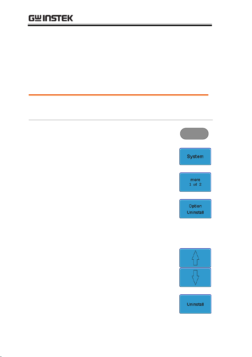
1. Press the Utility key.
Utility
2. Press System from the bottom
menu.
3. Press more 1 of 2 from the side
menu.
4. Press Option Uninstall on the side
menu.
5. Select the optional software packages that you
wish to uninstall from the side menu.
6. Use the Up and Down arrows on
the side menu to select an option to
uninstall.
7. Press Uninstall to uninstall the
option.
Uninstalling Optional Software
8
Page 9

QUICK REFERENCE
Options Menu Tree ......................................................... 10
Option Key ........................................................................... 10
Function Generator ............................................................. 10
Logic Analyzer ...................................................................... 11
Search - Logic ....................................................................... 11
Search - Bus .......................................................................... 12
Trigger - Bus ......................................................................... 13
Trigger - Logic ...................................................................... 14
Bus ......................................................................................... 14
Bus - UART .......................................................................... 15
Bus – I2C ............................................................................... 16
Bus – SPI ............................................................................... 17
Bus – Parallel ........................................................................ 18
QUICK REFERENCE
This chapter describes the menu tree for the
option software.
9
Page 10
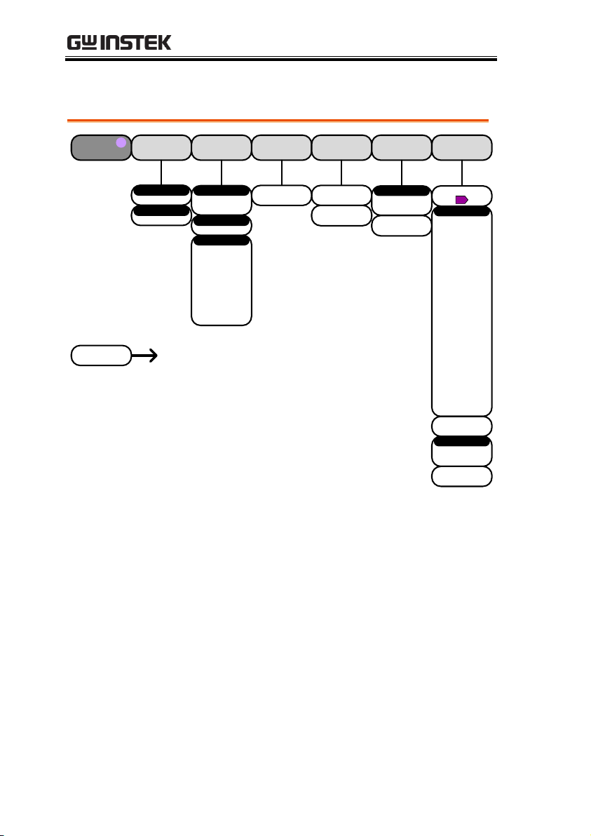
GDS-2000A Series Options Manual
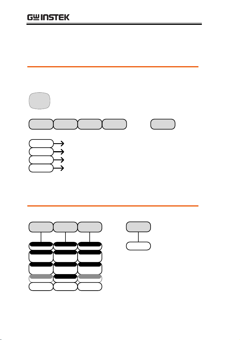
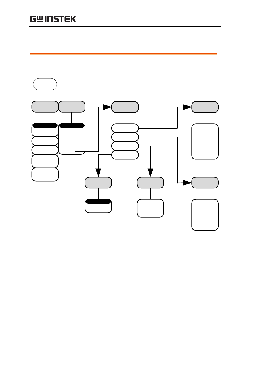
Accesses the functions in the Option menu.
Function
Gen 1
Function
Gen 2
I/O
Logic
Analyzer
Option
Logic
Analyzer
Function
Gen 1
Goes to the Logic Analyzer menu
Goes to the Function Generator menu
for the GEN 1 output
Function
Gen 2
Goes to the Function Generator
menu for the GEN 2 output
I/O
Goes to the options I/O menu
DVM
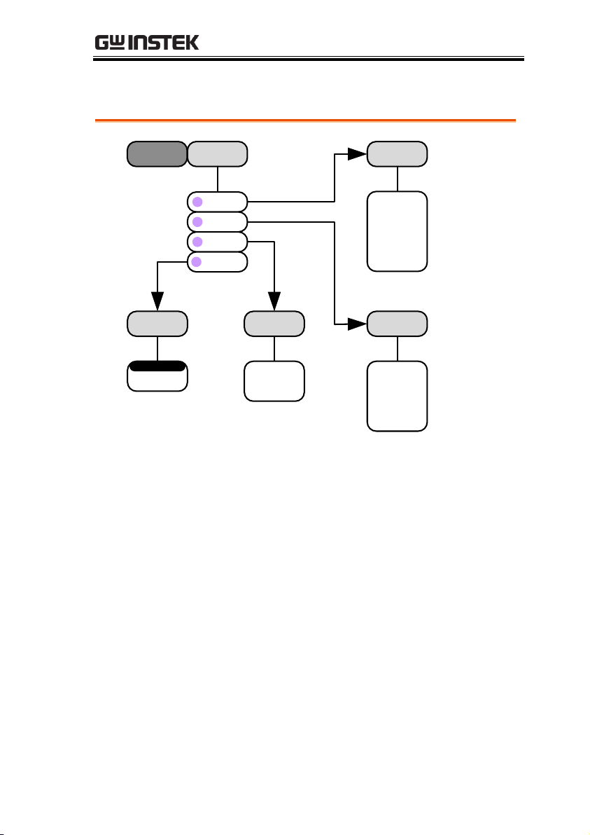
*Note: Any option that is not installed will be grayed-out.
Setup the Function Generator output.
Sine Square Triangle
0.1Hz ~ 5MHz
Frequency
30mVpp ~ 3Vpp
(into 50Ω)
Amplitude
±1.000V
(into 50Ω)
Offset
Dutycycle
Default
1kHz
0.1Hz ~ 5MHz
Frequency
30mVpp ~ 3Vpp
(into 50Ω)
Amplitude
±1.000V
(into 50Ω)
Offset
5% ~ 95%
Dutycycle
Default
1kHz
0.1Hz ~ 500kHz
Frequency
30mVpp ~ 3Vpp
(into 50Ω)
Amplitude
±1.000V
(into 50Ω)
Offset
Dutycycle
Default
1kHz
-20dB
ON
OFF
Options Menu Tree
Option Key
Function Generator
10
Page 11
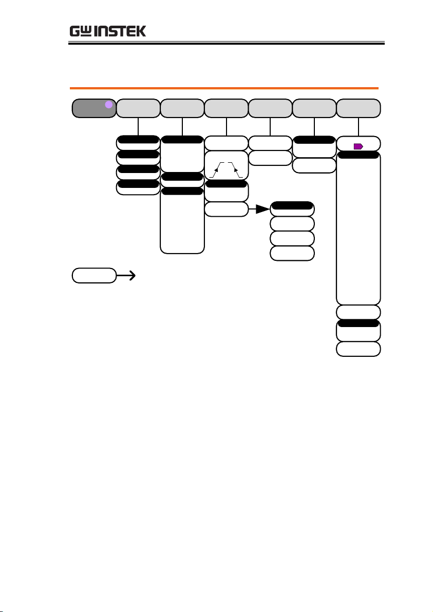
Logic Analyzer
Setup the Logic Analyzer inputs.
D15 – D0
On/Off
Thresholds
Analog
Waveform
Height
Sample Rate Go Back
D0 ~ D15
Select
On
Off
Set1~Set20
Filename.set
Display
On
Off
Turn On
Turn Off
Turn On
Turn Off
Display
D7~D0
D15~D8
Edit
Labels
D0~D3
D4~D7
D8~D11
D12~D15
Select
XX~XXV
Threshold
User
TTL
5.0V CMOS
3.3V CMOS
2.5V CMOS
ECL
PECL
0V
Choose Preset
Wave_A1
Wave_A2
Select
On
Off
Display
0.1~1.0 X
0.0~8.0 Div
Vertical
Edit
Labels
S
M
L
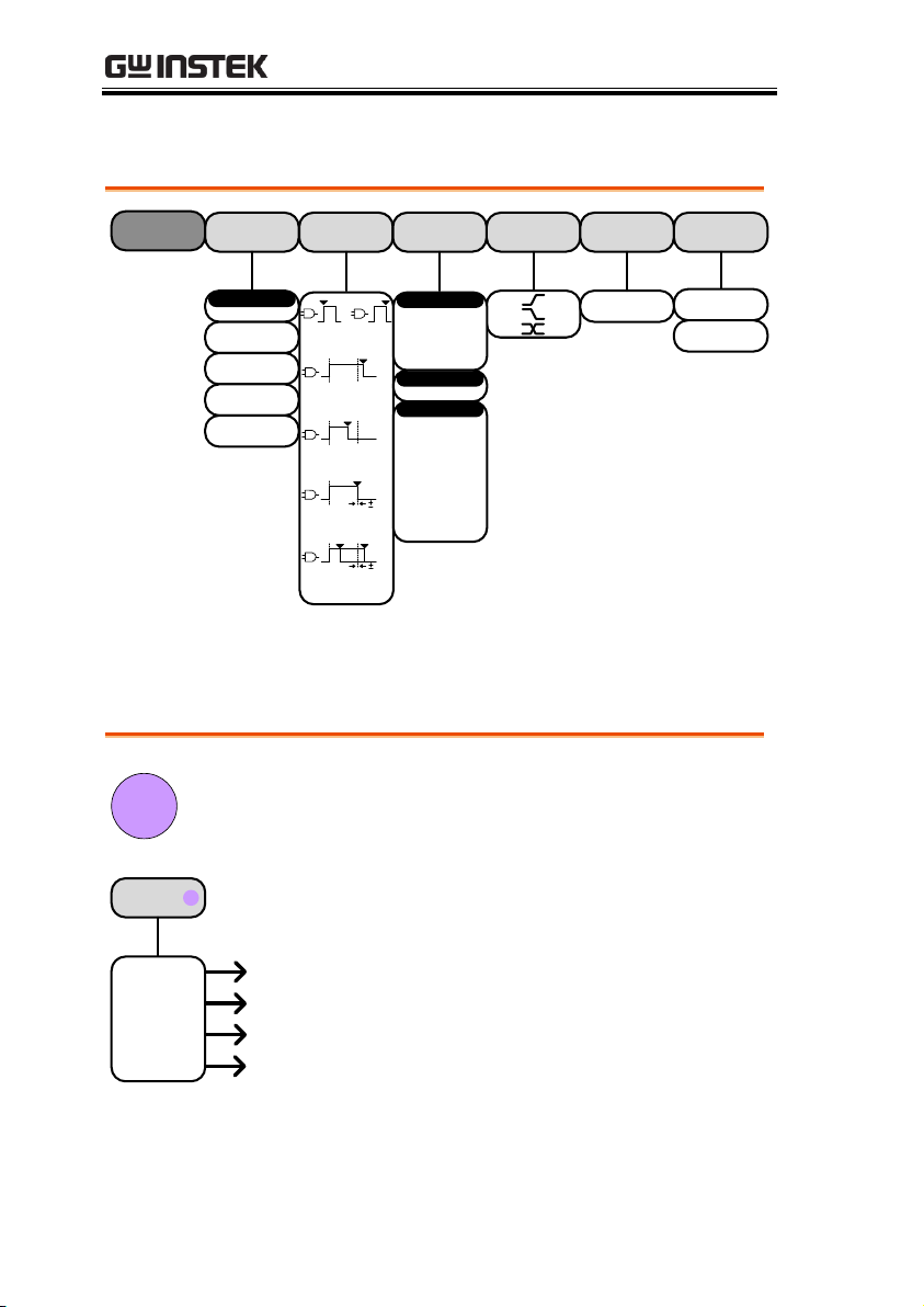
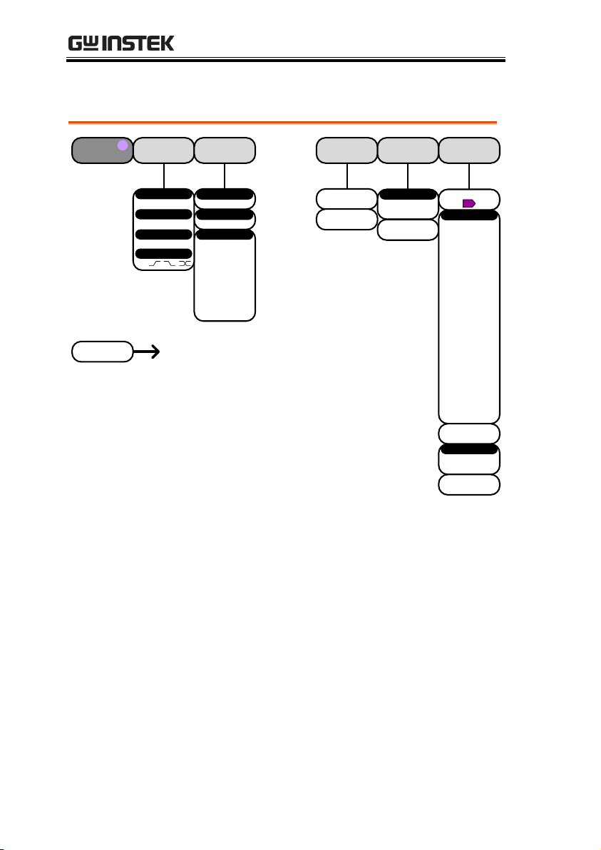
Set the Search function for logic events.
Edge
Pulse Width
Runt
Rise/Fall Time
Logic
Bus
Search
Clock EdgeWhen Threshold
Search
On
Off
Search
Save All
Marks
Clear All
Marks
Copy Trigger
Settings To
Search
Copy Search
Settings To
Trigger
Search Type
Define Inputs
Search
D0~D15
Select
Clock
High ( H )
Low ( L )
Don’t Care
( X )
5%
5%
Goes Goes
True False
Is True <
XXns
Is True =
XXns
Is True ≠
XXns
Is True >
XXns
D0~D3
D4~D7
D8~D11
D12~D15
Select
XX~XXV
Threshold
User
TTL
5.0V CMOS
3.3V CMOS
2.5V CMOS
ECL
PECL
0V
Choose Preset
Search - Logic
QUICK REFERENCE
11
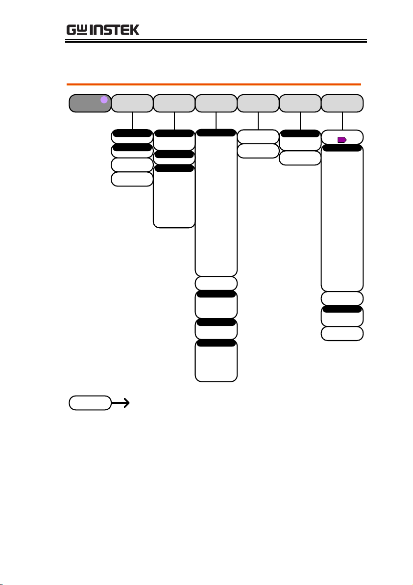
Page 12
Search - Bus
Set the Search function for bus events.
Note: The source bus is determined from the bus trigger settings.
Edge
Pulse Width
Runt
Rise/Fall Time
Logic
Bus
Search
Search On
Search
On
Off
Search
Save All
Marks
Clear All
Marks
Copy Trigger
Settings To
Search
Copy Search
Settings To
Trigger
Search Type
Source Bus
Search
UART*
I2C*
SPI*
Parallel*
Tx Start Bit
Rx Start Bit
Tx End of Packet
Rx End of Packet
Tx Data
Rx Data
Tx Parity Error
Rx Parity Error
Search On Search On
SS Active
MOSI
MISO
MOSI & MISO
Search On
Binary
Hex
Data
Start
Repeat Start
Stop
Missing Ack
Address
Data
Address/Data
*The source bus is determined from the bus trigger settings.
GDS-2000A Series Options Manual
12
Page 13
Trigger - Bus
Type
Bus
Source Bus
UART*
I2C*
SPI*
Parallel*
B
B
B
B
Search On
Tx Start Bit
Rx Start Bit
Tx End of Packet
Rx End of Packet
Tx Data
Rx Data
Tx Parity Error
Rx Parity Error
Trigger On
Start
Repeat Start
Stop
Missing Ack
Address
Data
Address/Data
Trigger On
SS Active
MOSI
MISO
MOSI & MISO
Trigger On
Binary
Hex
Data
*The source bus is set in the bus menu.
QUICK REFERENCE
13
Page 14
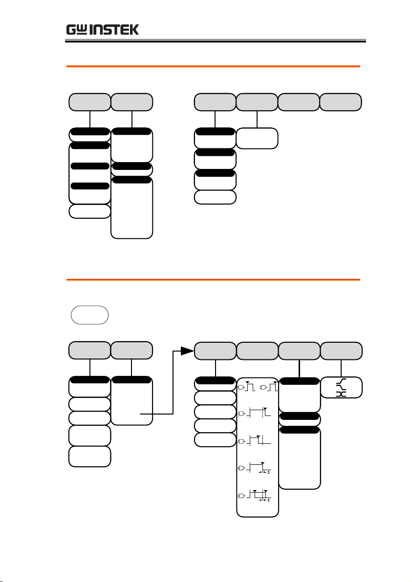
Trigger - Logic
Clock EdgeWhen Threshold
Define Inputs
D0~D15
Select
Clock
High ( H )
Low ( L )
Don’t Care
( X )
5%
5%
Goes Goes
True False
Is True <
XXns
Is True =
XXns
Is True ≠
XXns
Is True >
XXns
D0~D3
D4~D7
D8~D11
D12~D15
Select
XX~XXV
Threshold
User
TTL
5.0V CMOS
3.3V CMOS
2.5V CMOS
ECL
PECL
0V
Choose Preset
Type
Logic
Mode Holdof
Auto
Normal
10.0ns ~ 10.0s
Set to
Minimum
*The source bus is determined from the bus menu.
Bus
UART
I2C
SPI
Parallel
B
BUS
B
Goes to the UART bus menu
Goes to the I2C bus menu
Goes to the SPI bus menu
Goes to the Parallel bus menu
GDS-2000A Series Options Manual
Bus
14
Page 15
Define Inputs Threshold Configure
Bus Display
Event Table
Hex
Binary
Polarity Normal
(High = 0)
50, 75, 110,
134, 150, 300,
600, 1200,
1800, 2000,
2400, 3600,
4800, 7200,
9600, 14400,
15200, 19200,
28800, 19200,
28800, 31250,
38400, 56000,
57600, 76800,
115200,
128000,
230400,
460800,
921600,
1382400,
1843200,
2764800
Baud Rate
Edit Labels
Bus
UART
B
D0~D15
Tx Input
D0~D15
Rx Input
Polarity Inverted
(High = 1)
XX~XXV
Threshold
User
TTL
5.0V CMOS
3.3V CMOS
2.5V CMOS
ECL
PECL
0V
Choose Preset
Tx
Rx
Select
Data bits
8
Odd
Even
None
Parity
On
Off
Packets
00(NULL)
0A(LF)
0D(CR)
20(SP)
FF
End of Packet
On
Off
Event Table
Save
Event Table
ACK
AD0
ADDR
ANALOG
BIT
CAS
CLK
CLOCK
CLR
COUNT
DATA
DTACK
ENABLE
HALT
INT
IN
IRQ
LATCH
LOAD
NMI
User Preset
Edit Character
On
Off
Label Display
Label For
B
Go Back
Goes to the Keypad menuEdit Character
Bus - UART
QUICK REFERENCE
15
Page 16
Bus – I2C
Define Inputs Threshold
Include R/W
in address
Bus Display
Event Table
Hex
Binary
Edit Labels
Bus
I2C
B
D0~D15
SCLK
D0~D15
SDA
XX~XXV
Threshold
User
TTL
5.0V CMOS
3.3V CMOS
2.5V CMOS
ECL
PECL
0V
Choose Preset
SCLK
SDA
Select
On
Off
Event Table
Save
Event Table
ACK
AD0
ADDR
ANALOG
BIT
CAS
CLK
CLOCK
CLR
COUNT
DATA
DTACK
ENABLE
HALT
INT
IN
IRQ
LATCH
LOAD
NMI
User Preset
Edit Character
On
Off
Label Display
Label For
B
Go Back
Goes to the Keypad menuEdit Character
Yes
No
GDS-2000A Series Options Manual
16
Page 17
Bus – SPI
SCLK
SS
MOSI
MISO
Define Inputs Threshold Configure
Bus Display
Event Table
Hex
Binary
Edit Labels
Bus
SPI
B
D0~D15
SCLK Input
D0~D15
SS Input
XX~XXV
Threshold
User
TTL
5.0V CMOS
3.3V CMOS
2.5V CMOS
ECL
PECL
0V
Choose Preset
Select
On
Off
Event Table
Save
Event Table
ACK
AD0
ADDR
ANALOG
BIT
CAS
CLK
CLOCK
CLR
COUNT
DATA
DTACK
ENABLE
HALT
INT
IN
IRQ
LATCH
LOAD
NMI
User Preset
Edit Character
On
Off
Label Display
Label For
B
Go Back
Goes to the Keypad menuEdit Character
Yes
No
D0~D15
MOSI Input
D0~D15
MISO Input
more 1 of 2
SCLK
Active High
Active Low
SS
4~32 bits
Word Size
Bit Order
MS First
Bit Order
LS First
more 2 of 2
QUICK REFERENCE
17
Page 18
Bus – Parallel
Define Inputs Threshold
Bus Display
Event Table
Hex
Binary
Edit Labels
Bus
Parallel
B
XX~XXV
Threshold
User
TTL
5.0V CMOS
3.3V CMOS
2.5V CMOS
ECL
PECL
0V
Choose Preset
On
Off
Event Table
Save
Event Table
ACK
AD0
ADDR
ANALOG
BIT
CAS
CLK
CLOCK
CLR
COUNT
DATA
DTACK
ENABLE
HALT
INT
IN
IRQ
LATCH
LOAD
NMI
User Preset
Edit Character
On
Off
Label Display
Label For
B
Go Back
Goes to the Keypad menuEdit Character
Bit D0~D15
D0~D15
1~16
Off
Select Ch
Select Signal
Number of Bits
Clock Edge
D0~D15
Select
GDS-2000A Series Options Manual
18
Page 19

FUNCTION GENERATOR
Function Generator Operation ......................................... 20
Overview ............................................................................... 20
Function Generator Specifications ........................... 20
Using the Function Generator Option ............................. 21
Function Generator Calibration ......................................... 24
FUNCTION GENERATOR
19
Page 20
GDS-2000A Series Options Manual
Background
The DDS Function Generator module allows the
GDS-2000A to create basic sine, square and
triangle waveforms.
Note
The function generator option can only be used
with firmware version 1.13 or later. However it is
highly recommended that firmware version V1.16
or later be installed to access the full functionality
of the module. The instructions on the following
pages are based on V1.16 or later.
Please see the GW Instek website for the latest
firmware and the firmware installation procedure.
Waveforms
Sine, Square, Triangle
Frequency range
0.1Hz ~ 5MHz for sine
0.1Hz ~ 5MHz for square
0.1Hz ~ 500KHz for triangle
Frequency Stability
±50ppm
Frequency Accuracy
±50ppm (± 0.25Hz)
Aging
±5ppm/Year
Amplitude Range
60mVpp ~ 6Vpp (into 1MΩ)
30mVpp ~ 3Vpp (into 50Ω)
Amplitude Accuracy
±10%
Attenuator
-20dB
Impedance
50Ω
DC Offset
±2V (into 1MΩ)
±1V (into 50Ω)
Duty Control Range
5%(min) ~ 95%(max)
(Square wave only)
Rise or Fall Time
≤ 15ns (Square wave only)
Function Generator Operation
Overview
Function Generator Specifications
20
Page 21
FUNCTION GENERATOR
Background
This section will describe how to use the function
generator modules. To use the function generator
option, the DS2-FGN function generator module
must be installed. Please see page 6 for installation
details.
Note
The GDS-2000A can have two function generator
modules installed at the same time. Operating the
CDS-2000A using one or two function generator
modules is the same.
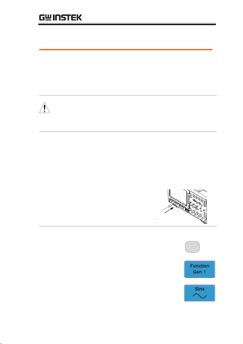
Connection
1. The function generator signal is output from
the GEN 1 or GEN 2 outputs on the front panel.
If the function generator module is installed in
slot one, then the signal is output from GEN 1,
and if the function generator is installed in slot
two, then the signal is output from GEN 2.
2. Connect a BNC cable
to the appropriate
output (GEN 1 or
GEN 2).
Panel Operation
1. Press the Option key.
Option
2. Press Function Gen 1 or Function
Gen 2 from the bottom menu.
3. Select Sine, Square or Triangle from
the bottom menu.
Using the Function Generator Option
21
Page 22

GDS-2000A Series Options Manual
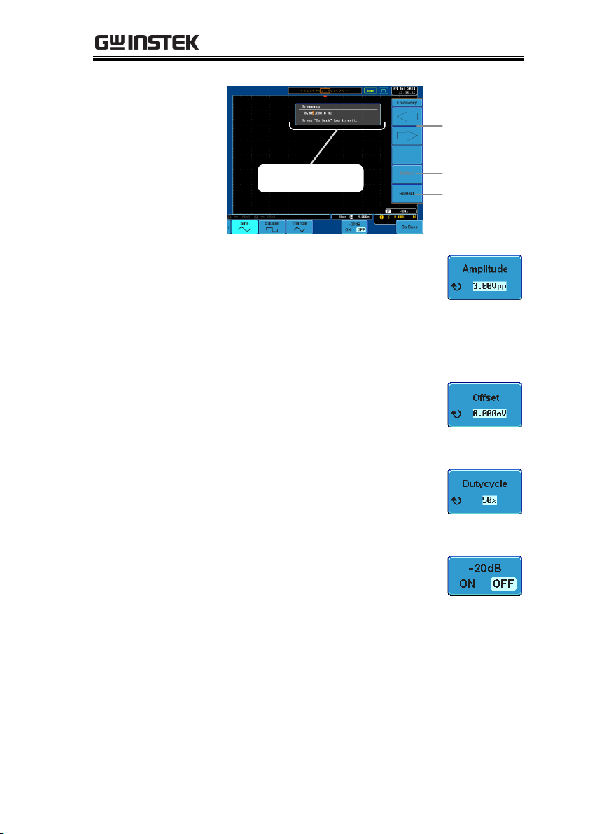
4. Press Frequency from
the side menu.
Use the Variable
knob to highlight
either User or a preset
frequency base unit.
The frequency can now be adjusted using fine
adjustment or coarse adjustment:
Range
100mHz ~ 5MHz (500kHz for
triangle)
COARSE ADJUSTMENT:
Press the Frequency soft-key again to reduce the
frequency menu.
Use the Variable knob to adjust the frequency
at the selected base unit.
The adjusted frequency will automatically be
saved to the User variable.
FINE ADJUSTMENT:
Press the Select key. The frequency can now be
adjusted one digit at a time.
Use the Left and Right soft-keys to select a
digit.
Use the Variable knob to adjust the digit.
Pressing the Default soft-key will return the
frequency back to the default base unit. (not
available for the User variable)
Press Go Back when you have finished
editing the frequency.
The adjusted frequency will automatically be
saved to the User variable.
22
Page 23
FUNCTION GENERATOR
Fine adjustment
mode
Left and
Right soft-
keys
Default
Go Back
5. Press the Amplitude key to set the
amplitude.
Range
300mVpp ~ 3Vpp (into 50Ω load)*.
*range depends on attenuation
settings.
6. Press the Offset key to set the DC
offset.
Range
±1.000V (into 50Ω load).
7. Press DutyCycle (Square wave
only) to set the duty cycle.
Range
5% to 95%.
8. Press -20dB to attenuate the output
by 20dB.
Range
ON, OFF
9. The signal will be output immediately from the
GEN 1 or GEN 2 outputs.
23
Page 24
GDS-2000A Series Options Manual
Background
The function generator module can also be
calibrated from the System menu. The calibration
function is only available for firmware version
V1.16 or later.
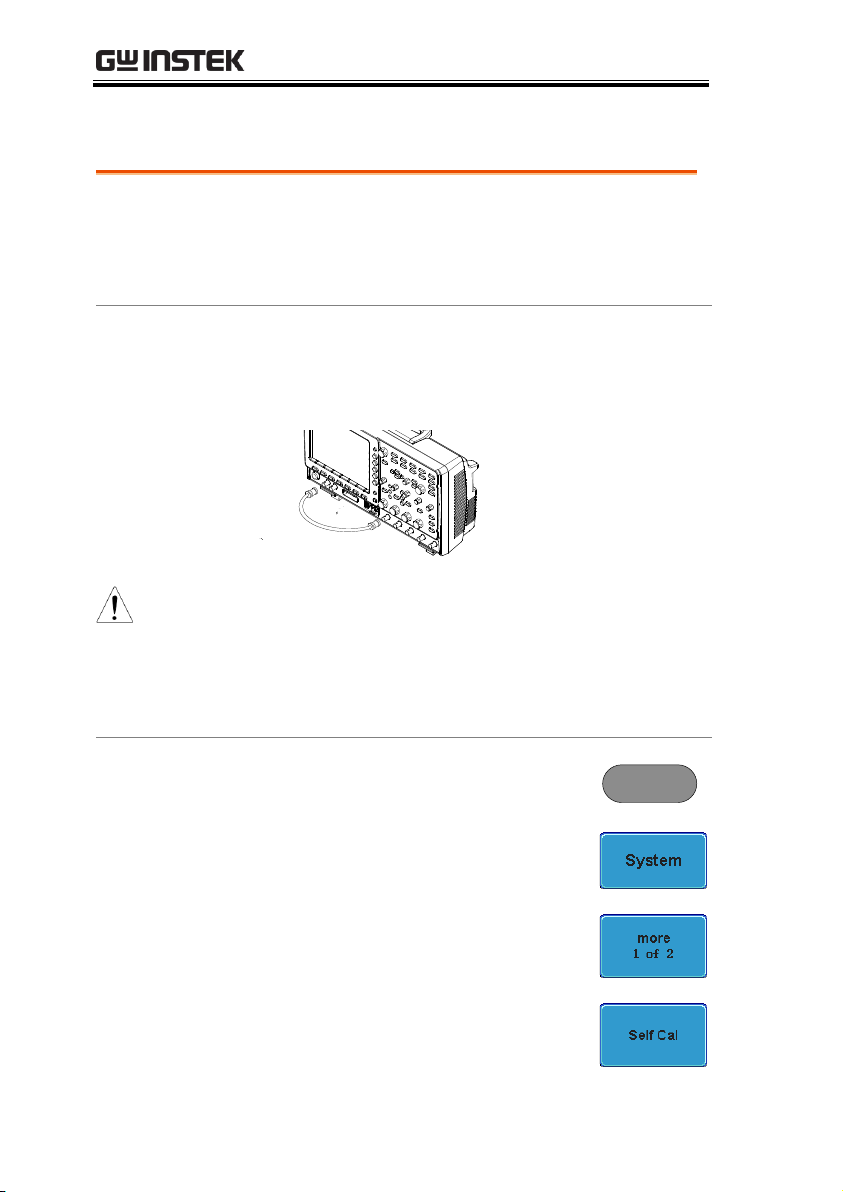
Connection
Connect the GEN 1 or GEN 2 output (depending
on which module slot the function generator is
installed in) to CH1 using a BNC cable.
CH1
GEN 1
or
GEN 2
Note
If two function generator modules are installed,
the system will automatically choose to calibrate
the function generator in module slot 1. If you
wish to calibrate the second function generator,
first select it from the Option menu (Option key >
Function Gen 2).
Panel Operation
1. Press the Utility key.
Utility
2. Press System from the bottom
menu.
3. Press More 1 of 2 from the side
menu.
4. Press Self CAL from the side menu.
Function Generator Calibration
24
Page 25
FUNCTION GENERATOR
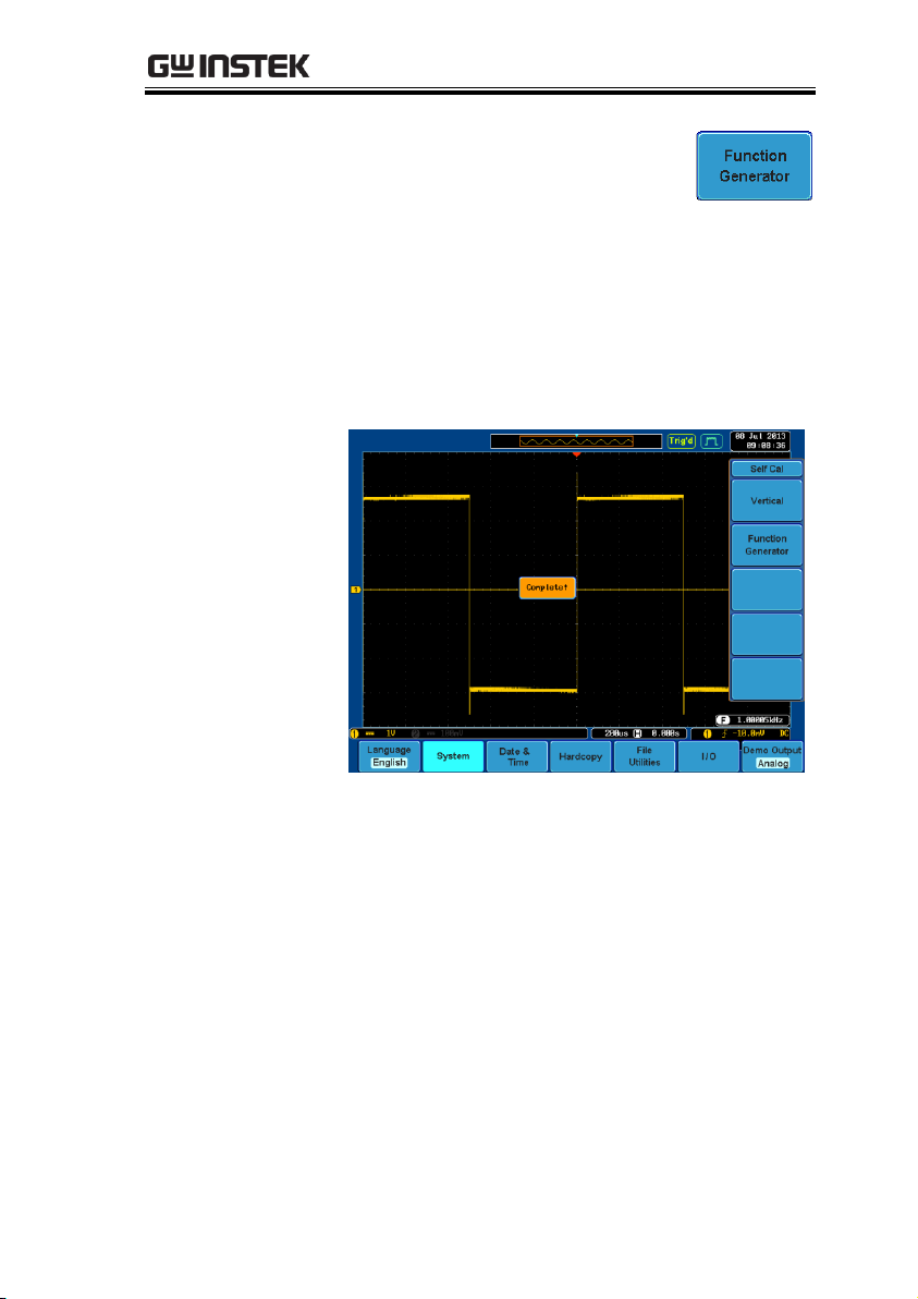
5. Press Function Generator from the
side menu.
Wait a few moments for the calibration to
finish. “Complete” will be displayed on the
screen when the calibration has completed.
If the calibration fails, please check the
connection and perform the calibration
procedure again.
25
Page 26

GDS-2000A Series Options Manual
Logic Analyzer Operation ................................................ 28
Overview ............................................................................... 28
Using the Logic Analyzer Probes ....................................... 29
Digital Display Overview .................................................... 30
Activating Digital Channels ................................................ 31
Activate Digital Channels as a Group ...................... 31
Activate Individual Channels .................................... 32
Moving the Digital Channels or Creating Digital
Channel Groups .......................................................... 33
Digital Channel Vertical Scale ............................................ 38
Digital Channel Threshold Levels ..................................... 38
Analog Waveform ................................................................ 40
Adding Labels to Digital Channels .................................... 41
Bus Key Configuration ..................................................... 44
Bus Display ........................................................................... 44
Parallel Bus ............................................................................ 46
Input Configuration ................................................... 46
Threshold Configuration ........................................... 47
Bus Encoding .............................................................. 48
Parallel Bus Event Table ............................................ 49
Adding a Label to the Parallel Bus ........................... 50
Serial Bus ............................................................................... 53
Serial Bus Overview ................................................... 53
UART Serial Bus Configuration ............................... 54
I2C Serial Bus Interface .............................................. 56
SPI Serial Bus Interface ............................................. 57
Bus Encoding .............................................................. 59
Threshold Configuration .................................................... 59
Serial Bus Event Tables ............................................. 61
Event Tables Format .................................................. 64
Adding a Label to the Serial Bus............................... 65
Using Cursors with the Serial Bus ............................ 67
LOGIC ANALYZER
26
Page 27

LOGIC ANALYZER
Trigger Settings ............................................................... 69
Serial Bus Trigger Settings .................................................. 69
UART BUS Trigger Settings ..................................... 69
I2C Bus Trigger Settings ............................................. 70
SPI Bus Trigger Settings ............................................ 73
Parallel Bus Trigger .............................................................. 74
Common Bus Trigger Settings ........................................... 75
Bus Trigger Mode ....................................................... 75
Logic Trigger ........................................................................ 76
Logic Trigger Mode .................................................... 79
Logic Trigger Holdoff ................................................ 79
27
Page 28

GDS-2000A Series Options Manual
Background
The Logic Analyzer inputs can only be used when
a Logic Analyzer option is installed (GW Instek
part no. DS2-8LA or DS2-16LA). Both the 8-chanel
and 16-channel models have a sample rate of
500MSa/s with bandwidth of 200MHz.
The logic analyzer inputs can be used to measure
discrete inputs or can be used to measure values
on a parallel or serial bus.
Supported Logic
Thresholds
TTL, CMOS,
ECL, PELC,
User- defined
The GDS-2000A supports common
logic thresholds and supports
user-defined thresholds of ± 10V if
the in-built threshold levels are
unsuitable.
Digital Trigger
Types
Edge, Pulse
Width, Rise and
Fall, Bus, Logic
As standard, the digital channels
support basic edge, pulse width,
rise and fall as well as bus and
logic triggers.
Logic Analyzer Operation
Overview
28
Page 29

LOGIC ANALYZER
Background
This section will describe how to connect the
digital channels to the device under test. To use the
digital channels the optional logic analyzer module
must be installed. Please see page 6 to install the
logic analyzer module.
Connection
1. Turn the DUT off to protect it from being short
circuited when the probes are attached.
2. Insert the Logic
Analyzer probe into
the Logic Analyzer
input.
3. Connect the ground lead from the logic
analyzer probe to the circuit ground on the
DUT.
GND
4. Connect another probe lead to a point of
interest on the circuit. Make note of which
probe lead is connected to which point.
5. Repeat step 3 with any remaining probes.
Signal 2
Signal 3
GND
Signal 1
….
Using the Logic Analyzer Probes
29
Page 30

GDS-2000A Series Options Manual
Analog
waveform
indicator
Digital
channel
indicators
Digital waveforms
Analog waveform
Digital
channel
group
Analog Waveform
Indicator
Used to show the position of the analog waveform
outputs.
Active analog
waveform
Activated analog
waveform
Digital Channel
Indicators
Used to show the position and grouping of the
digital channels.
Active digital channel
Activated digital
channel
Digital Channel
Group
When digital channels are grouped together,
they are shown as being pinned together.
When grouped, digital channels can moved
as a single group.
Digital Display Overview
30
Page 31

LOGIC ANALYZER
Background
The digital channels can be turned on or off in
groups of eight, D0~D7 and D8~D15.
Panel Operation
6. Press the Option key.
Option
7. Press Logic Analyzer from the
bottom menu.
8. Press D15 – D0 On/Off key.
9. Select which group of digital
inputs you want turned on or off
from the side menu.
Group1
D0~D7
Group2
D8~D15
10. The digital channels will appear on the
graticule.
Note
When all the digital channels are turned on, they
will appear as a single group.
Activating Digital Channels
The digital channels can be initially turned on in groups of 8 or
individually.
Activate Digital Channels as a Group
31
Page 32

GDS-2000A Series Options Manual
Background
Each digital channel or group can be turned on or
off individually.
Panel Operation
1. Press the Select soft-key.
2. Use the variable knob to highlight
a channel or a group.
VARIABLE
3. A 'tick' next to a particular channel or group
indicates that that channel or group is currently
on.
Channel 0~2 is off
Channel 3~15 is on
4. Press the Display soft-key or the
Select key to toggle the selected
channel or group on or off.
or
Select
Activate Individual Channels
32
Page 33

LOGIC ANALYZER
5. Press the Select soft-key again to
reduce the menu.
Note
Channels can also be selected just by turning the
variable knob when the mode is set to LA move mode.
In this mode the selected channel or group will be
shown on the Select soft-key. However this method
will only show those channels/groups that have
already been turned on. See page 33 for details.
Note
The digital channels must first be activated. See
page 31.
Background
The logic analyzer has two basic modes of
operation for selecting or moving digital channels.
LA Select mode: This mode is used to select digital
channels that have already been activated.
LA Move mode: This mode is used to move the
vertical position of the digital channels and to
group digital channels into groups.
The Select key is used to toggle between both
modes when in the D15~D0 On/Off menu.
Panel Operation
1. Press the D15~D0 On/Off key. The
scope will initially be in 'LA Select
mode'.
Moving the Digital Channels or Creating Digital Channel Groups
33
Page 34

GDS-2000A Series Options Manual
2. Use the variable knob to choose a
channel or group. The selected
channel/group will be shown on
the Select key. Only channels that
have been activated can be selected
this way.
VARIABLE
Below, channel 4 is selected.
Channel 4 is selected
Note: If the Variable knob cannot select a channel,
press the Select key to toggle the scope into 'LA
Select mode'.
3. Press the Select key. The mode
toggles from 'LA Select mode' to
'LA Move mode'.
A message will indicate which
mode is currently active.
Select
34
Page 35

LOGIC ANALYZER
The Move mode is used to move the digital
channel position on the graticule as well as to
group the channels. If you turned on all the
digital channels, you will notice that they are
already grouped as a single group.
You can tell when it is in move mode as the
selected channel/group flashes and the labels
for the other channels/groups become grayed
out.
Channel 4 is in the
'Move' mode and
the labels for the
other channels are
grayed out
4. Use the variable knob to position
the selected channel/group:
VARIABLE
If you position the channel indicator over the
next/previous channel, it will split the group
into 2.
Split the group above the selected channel:
Split the group below the selected channel:
35
Page 36

GDS-2000A Series Options Manual
If you continue to move the channel indicator
past the next/previous channel, it will move the
indicator anywhere within that group.
5. If you move the indicator outside of the group,
it will remove the selected channel from the
group.
36
Page 37

LOGIC ANALYZER
6. Press the Select key again. This will
return you to the LA Select mode.
You can tell when it is in the Select
mode as no channel will be grayed
out.
Select
37
Page 38

GDS-2000A Series Options Manual
Background
The digital channels have 3 preset scales, S, M, L.
Panel Operation
1. From the D15~D0 On/Off menu,
press Height to toggle the vertical
scale of the digital channels.
Height
S, M, L
Note
If more than 8 digital channels are active, the large (L)
option will be disabled.
Note
Threshold levels can be set to four groups of
digital channels: D0~D3, D4~7, D8~D11 and
D12~D15. Each group can have a different
threshold level.
The GDS-2000A has 4 preset threshold levels and a
user-defined threshold. A user-defined threshold
level can be set for each group. Any signal over the
threshold level corresponds to a high (1), any
signal under the threshold level is a low (0).
Panel Operation
1. From the D15~D0 On/Off menu,
press the Thresholds soft-key.
2. Press Select from the side menu
and choose a group of channels.
Digital Channel Vertical Scale
Digital Channel Threshold Levels
38
Page 39

LOGIC ANALYZER
3. Press Choose Preset to select a pre-
set logic threshold.
Logic Type
Threshold
TTL
1.4V
5.0V CMOS
2.5V
3.3V CMOS
1.65V
2.5V CMOS
1.25V
ECL
-1.3V
PECL
3.7V
0V
0V
4. Press Threshold to set a user
defined threshold for the currently
selected group.
Range
±10V
39
Page 40
GDS-2000A Series Options Manual
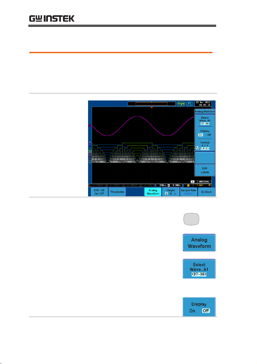
Background
The analog waveform function combines the
digital channel inputs into two 8-bit analog
waveforms. The analog waveforms are created
from the digital channel groups D0~7 and D8~15.
Example
Panel Operation
1. Press the Option key.
Option
2. Press the Analog Waveform key.
3. Press Select and select which
analog waveform you which to
display, Wave_A1 (D7~D0) or
Wave_A2 (D15~D8).
Display on Screen
4. Press Display to display the
selected waveforms on the screen.
Analog Waveform
40
Page 41

LOGIC ANALYZER
Set Vertical
Position
5. Press Vertical until div parameter is
highlighted. Use the Variable knob
to set the position.
Set Vertical Scale
6. Press Vertical until X scale
parameter is highlighted. Use the
Variable knob to set the scale.
Edit Labels
7. Press Edit Labels to edit the label
for the currently selected analog
waveform. See page 41 for details.
Note
Only one analog waveform can be displayed at a time.
Background
Digital labels can be added to each digital channel
or to one of the analog waveforms.
Panel Operation
1. To edit labels for the digital
channels, press the Edit Labels softkey from the D15~D0 On/Off
menu.
To edit labels for the analog
waveforms, press the Edit Labels
soft-key from the Analog Waveform
menu.
2. Press Label For and select a channel
or waveform.
Label For
D0~D15
A1, A2
Adding Labels to Digital Channels
41
Page 42

GDS-2000A Series Options Manual
3. To choose a preset label, Press User
Preset from the side menu and
choose a label.
Labels
ACK, AD0, ADDR, ANALOG,
BIT, CAS, CLK, CLOCK, CLR,
COUNT, DATA, DTACK,
ENABLE, HALT, INT, IN, IRQ,
LATCH, LOAD, NMI
Edit Label
4. Press Edit Character to edit the
current label.
5. The Edit Label window appears.
6. Use the Variable knob to highlight
a character.
VARIABLE
42
Page 43

LOGIC ANALYZER
Press Enter Character to select a
number or letter.
Press Back Space to delete a
character.
Press Editing Completed to create
the new label and return to the
previous menu.
Note: this key must be pressed to
create a label, even for a preset
label.
Press Cancel to cancel the editing
and return to the Edit Label
menu.
7. The label will appear next to corresponding
channel indicator.
Below, the label “LABEL_1” was created for
the D0 channel.
D0 is labeled as
LABEL_1
Remove Label
Press Label Display to toggle the
selected label on or off.
43
Page 44

GDS-2000A Series Options Manual
Bus indicator
Digital channel indicators
Trigger
configuration
Data Start bit Stop bit
Start Bit
The Start bit is shown as a open bracket (Serial bus
data only).
Stop Bit
The Stop bit is shown as an closed bracket (Serial
bus data only).
Data
Data packets can be shown in Hex or Binary. The
color of the packet is the same as the channel color.
Error Indicator
If there is an error in decoding the serial data, an
error indicator will be shown.
Bus Indicator
The Bus indicator shows the bus position. The
active bus is shown with a solid color. The Variable
knob can be used to horizontally position the Bus
indicator when it is active.
Active bus
(solid indicator)
Activated bus
(transparent indicator)
Bus Key Configuration
The Bus key is used to configure the Parallel and Serial bus inputs.
The Bus menu also features an event tables to track and save your
bus data.
Bus Display
44
Page 45

LOGIC ANALYZER
Trigger
Configuration
Shows the bus trigger (B) and the Trigger On
settings.
45
Page 46
GDS-2000A Series Options Manual
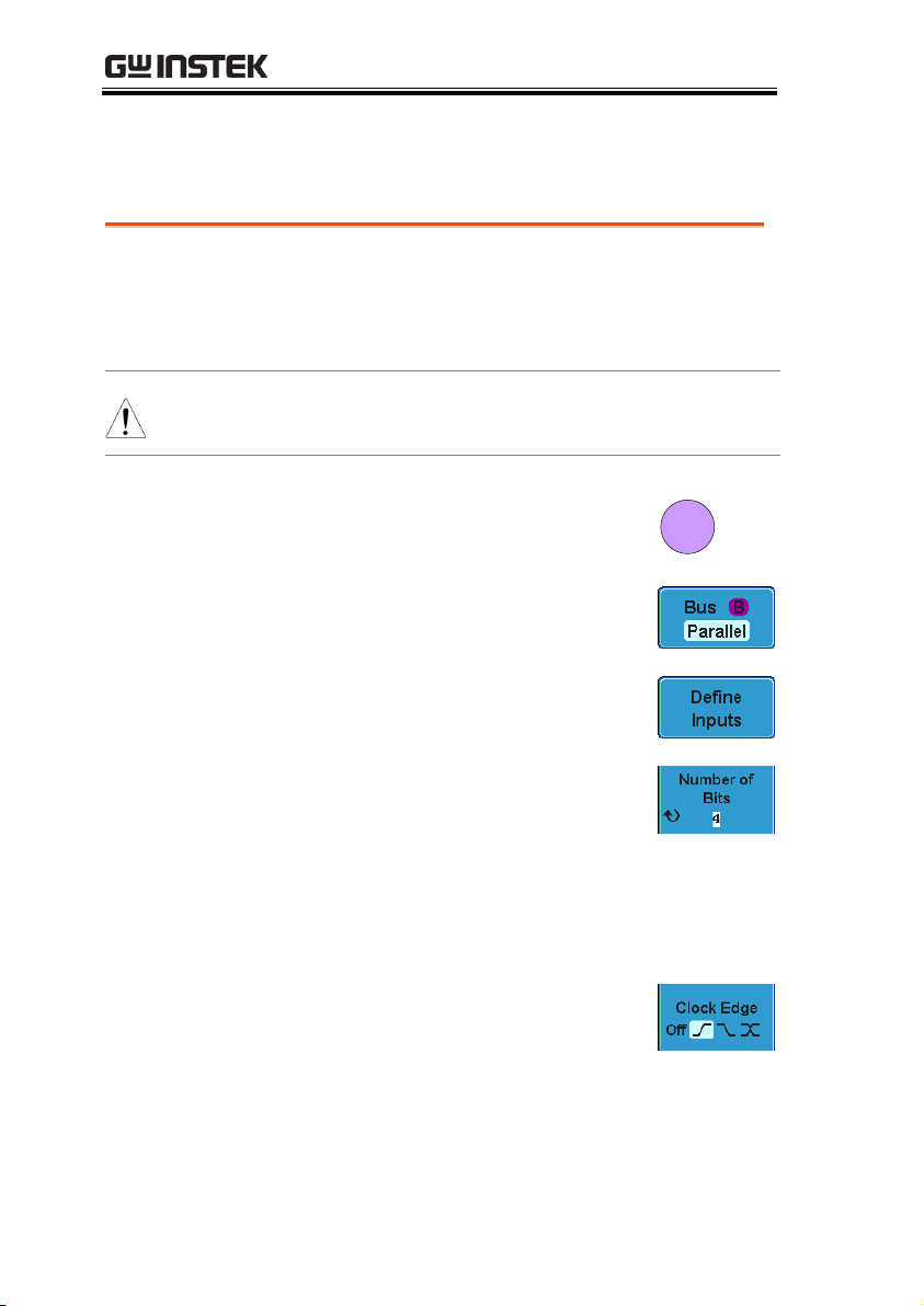
Background
The digital channels can be configured as a parallel
bus. The number of bits that define the bus as well
as which bit is used as the bus clock can also be
configured.
Note
The trigger should also be set to parallel bus.
Please see page 74 for details.
Panel Operation
1. Press the Bus key.
B
BUS
2. Press the Bus soft-key and select
Parallel from the side menu.
3. Press Define Inputs from the bottom
menu.
4. Press Number of Bits from the side
menu and select the number of bits
for the data bus.
By default the bus is assigned bits
D0, D1, D2 and so on up to the last
bit.
5. You may also assign a bit as a
clock. This bit will be one of the
bits in the bus. To add a clock bit,
press Clock Edge and select type of
clock edge. Selecting Off will
disable the clock bit.
Parallel Bus
Input Configuration
46
Page 47

LOGIC ANALYZER
6. If you wish to define which channels are
assigned to the bus, press Select Signal from the
side menu and select the bit that wish to assign.
Channel 1 is
currently
assigned to bit 1.
7. Next, press Select Ch and select
which channel is assigned to the
bit selected above.
8. Repeat steps 6 and 7 for any remaining bits and
for the clock, if enabled.
Background
The threshold levels for the parallel bus can be set
to either a user-defined threshold level or to preset threshold.
Operation
1. Press Thresholds from the bottom
menu.
2. Press Select from the side menu
and select a digital channel.
3. Press Choose Preset to select a pre-
set logic threshold for the selected
channel.
Logic Type
Threshold
TTL
1.4V
5.0V CMOS
2.5V
Threshold Configuration
47
Page 48

3.3V CMOS
1.65V
2.5V CMOS
1.25V
ECL
-1.3V
PECL
3.7V
0V
0V
4. Press Threshold to set a user
defined threshold for the selected
input.
Range
±10V
Note
Setting the threshold levels from the Bus menu will
also change the threshold levels set in the Logic
Analyzer menu (page 38).
Bus Encoding
Background
The bus that is displayed on the screen or in the
event tables can be set to either hex or binary
formats.
Operation
Press Bus Display from the Bus
menu and choose either Hex or
Binary from the side menu.
GDS-2000A Series Options Manual
48
Page 49

LOGIC ANALYZER
Event Table
The parallel bus event table lists when each data
event on the bus occurred. The data is displayed as
either hex or binary, depending on the bus display
settings.
Event tables can be saved to disk in a CSV format. The
files will be named “Event_TableXXXX.CSV”, where
XXXX is a number from 0000 to 9999. See page 64 for
details.
Operation
1. Press Event Table from the bottom
menu.
2. Press Event Table from the side
menu to turn the event table on or
off.
Event
On, Off
3. To save the event table, press Save
Event Table.
Use the variable knob to scroll through the
event table.
Parallel Bus Event Table
49
Page 50

GDS-2000A Series Options Manual
Example
Time of event
Event data
Background
A label can be added to the parallel bus.
Panel Operation
1. To add a label to the bus, press
Edit Labels from the Parallel Bus
menu.
2. To choose a preset label, Press User
Preset from the side menu and
choose a label.
Labels
ACK, AD0, ADDR, ANALOG,
BIT, CAS, CLK, CLOCK, CLR,
COUNT, DATA, DTACK,
ENABLE, HALT, INT, IN, IRQ,
LATCH, LOAD, NMI
Edit Label
3. Press Edit Character to edit the
current label.
Adding a Label to the Parallel Bus
50
Page 51

LOGIC ANALYZER
4. The Edit Label window appears.
5. Use the Variable knob to highlight
a character.
VARIABLE
Press Enter Character to select a
number or letter.
Press Back Space to delete a
character.
Press Editing Completed to create
the new label and return to the
previous menu.
Note: this key must be pressed to
save the label, even for the preset
labels.
51
Page 52
GDS-2000A Series Options Manual
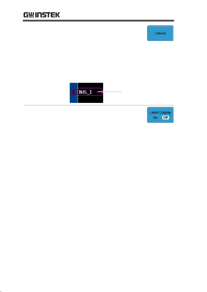
Press Cancel to cancel the editing
and return to the Edit Label
menu.
6. The label will appear next to the bus indicator.
Below, the label “BUS_1” was created for the
parallel bus.
The parallel bus is
labeled as BUS_1
Remove Label
Press Label Display to toggle the label
on or off.
52
Page 53

LOGIC ANALYZER
UART
Universal Asynchronous Receiver Transmitter.
The UART bus is able to accommodate a wide
range of various common UART serial
communications.
The UART serial bus software is suitable for a
number of RS-232 protocol variants.
Inputs
Tx, Rx
Threshold
Tx, Rx
Configuration
Baud rate, Parity, Packets, End of
packets, Input polarity
Trigger On
Tx Start Bit, Rx Start Bit, Tx End of
Packet, Rx End of Packet, Tx Data,
Rx Data, Tx Parity Error, Rx Parity
Error
I2C
Inter Integrated Circuit is a two line serial data
interface with a serial data line (SDA) and serial
clock line (SCLK). The R/W bit can be configured.
Inputs
SCLK, SDA
Threshold
SCLK, SDA
Configuration
Addressing mode, Read/Write in
address
Trigger On
Start, Repeat Start, Stop, Missing
Ack, Address, Data, Address/Data
Serial Bus
The Serial Bus for Logic Analyzer software includes support for 3
common serial interfaces, SPI, UART and I2C. Each interface is fully
configurable to accommodate variations in the basic protocols.
Each input can be displayed as binary or hexadecimal. An event
table can also be created to aid in debugging.
Serial Bus Overview
53
Page 54

GDS-2000A Series Options Manual
SPI
The SPI (Serial Interface Peripheral) bus is fully
configurable to accommodate the wide variety of
SPI interfaces. This bus is only available on 4
channel models.
Inputs
SCLK, SS, MOSI, MISO
Threshold
SCLK, SS, MOSI, MISO
Configuration
SCLK edge, SS logic level, Word
size, Bit order
Trigger On
SS Active, MOSI, MISO,
MOSI&MISO
Background
Basic RS-232 protocol uses single-ended data
transmissions. The signal voltage levels can be
high (±15V)* and employ active low signaling.
High speed variants of RS-232, such as RS-422 and
RS-485 use differential signaling and commonly
employ low voltage differential signals with active
high signaling.
Universal Asynchronous Receiver / Transmitter
(UART) or RS-232 driver/receiver ICs commonly
used for embedded applications typically use
active high signaling with standard IC signal
levels.
*Note: the GDS-2000A does not support ±15V
signaling for the Logic Analyzer inputs)
UART Serial Bus Configuration
The UART bus menu is designed to decode RS-232 and other
common RS-232 variants such as RS-422, RS-485. The software
configuration is also flexible enough to decode the many
proprietary protocols based on RS-232.
54
Page 55

LOGIC ANALYZER
Operation
1. Connect each of the bus signals (Tx, Rx) to one
of the logic analyzer inputs. Connect the
ground potential of the bus to the logic
analyzer’s ground probe line.
GND
Rx
Tx
2. Press the Bus key.
B
BUS
3. Press Bus from the bottom menu
and choose the UART serial bus on
the side menu.
Define Inputs
4. Press Define Inputs from the bottom
menu.
5. From the side menu choose the Tx
Input and the Rx
Input source and the signal
polarity.
Tx
OFF, D15~D0
Rx
OFF, D15~D0
Polarity
Normal (High = 0), Inverted (High
= 1)
Configuration
The Configure key sets the baud rate, number of data
bits and parity.
55
Page 56

GDS-2000A Series Options Manual
1. Press Configure from the bottom
menu.
2. From the side menu select the Baud rate, Data
bits, Parity, Packets and End of Packet bits.
Baud Rate
50, 75, 110, 134, 150, 300, 600, 1200,
1800, 2000, 2400, 3600, 4800, 7200,
9600, 14400, 15200, 19200, 28800,
31250, 38400, 56000, 57600, 76800,
115200, 128000, 230400, 460800,
921600, 1382400, 1843200, 2764800
Data Bits
8 (fixed)
Parity
Odd, Even, None
Packets
On, Off
End of
Packet
(Hex)
00(NUL), OA(LF), OD(CR), 20(SP),
FF
Panel operation
1. Connect each of the bus signals (SCLK, SDA) to
one of the logic analyzer inputs. Connect the
ground potential of the bus to the logic
analyzer’s ground probe line.
I2C Serial Bus Interface
The I2C bus is a 2 wire interface with a serial data line (SDA) and
serial clock line (SCLK). The I2C protocol supports 7 or 10 bit
addressing and multiple masters. The decode software will trigger
on any of the following conditions: a start/stop condition, a restart,
a missing acknowledge message, Address, Data or Address&Data
frames. The I2C trigger can be configured for 7 or 10 bit addressing
with the option to ignore the R/W bit as well as triggering on a
data value or a specific address and direction (read or write or
both).
56
Page 57

LOGIC ANALYZER
GND
SCLK
SDA
2. Press the Bus key.
B
BUS
3. Press Bus from the bottom menu
and choose I2C from the side menu.
Define Inputs
4. Press Define Inputs from the bottom
menu.
5. From the side menu choose the
SCLK input and the SDA Input.
SCLK
D15~D0
SDA
D15~D0
Include R/W in
address
To configure whether you want the
R/W bit to be included in the
address, press Include R/W in
address and set to Yes or No in the
side menu.
R/W Bit
Yes, No
SPI Serial Bus Interface
The serial peripheral interface (SPI) is a full duplex 4 wire
synchronous serial interface. The 4 signals lines: Serial clock line
(SCLK), slave select (SS), Master output/slave input (MOSI, or
57
Page 58
GDS-2000A Series Options Manual
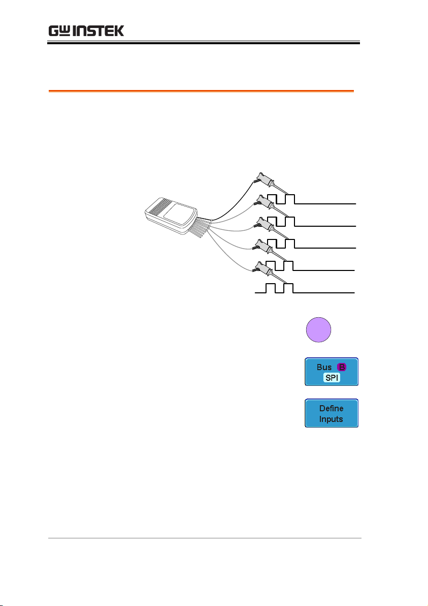
Panel operation
1. Connect each of the bus signals (SCLK, SS,
MOSI, MISO) to one of the logic analyzer
inputs. Connect the ground potential of the bus
to the logic analyzer’s ground probe line.
GND
SCLK
SS
MOSI
MISO
2. Press the Bus key.
B
BUS
3. Press Bus from the bottom menu
and choose the SPI serial bus.
Define Inputs
4. Press Define Inputs from the lower
menu.
5. From the side menu choose the
SCLK, SS, MOSI and MISO inputs.
SCLK
D15~D0
SS
D15~D0
MOSI
OFF, D15~D0
MISO
OFF, D15~D0
SIMO) and the Master input/slave output (MISO, or SOMI). The
word size is configurable from 4 to 32 bits. The SPI triggers on the
data pattern at the start of each framing period.
58
Page 59

Configuration
The Configure menu sets the data line logic level,
SCLK edge polarity, word size and bit order.
1. Press Configure from the bottom
menu.
2. From the side menu select SCLK edge, SS logic
level, word Size and Bit order.
SCLK
rising edge , falling edge
SS
Active High, Active Low
Word Size
4 ~ 32 bits
Bit Order
MS First, LS First
Bus Encoding
Background
The bus that is displayed on the screen or in the
event tables can be set to either hex or binary
formats.
Operation
Press Bus Display from the Bus
menu and choose either Hex or
Binary from the side menu.
Background
The threshold levels for the Serial buses can be set
to either a user-defined threshold level or to preset threshold.
Set the Threshold
1. Press Threshold from the bottom
menu.
LOGIC ANALYZER
Threshold Configuration
59
Page 60
GDS-2000A Series Options Manual
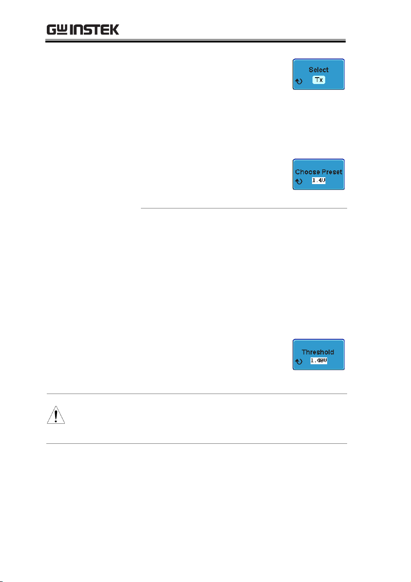
2. Press Select from the side menu
and choose a one of the serial bus
lines.
UART
Tx, Rx
I2C
SCLK, SDA
SPI
SCLK, SS, MOSI, MOSI
3. Press Choose Preset to select a pre-
set logic threshold.
Logic Type
Threshold
TTL
1.4V
5.0V CMOS
2.5V
3.3V CMOS
1.65V
2.5V CMOS
1.25V
ECL
-1.3V
PECL
3.7V
0V
0V
4. Press Threshold to set a user
defined threshold for the currently
selected group.
Range
± 10V
Note
Setting the threshold levels from the Bus menu will
also change the threshold levels set in the Logic
Analyzer menu (page 38).
60
Page 61

LOGIC ANALYZER
Background
The serial bus event tables list when each data
event on the bus occurred. The data is displayed as
either hex or binary, depending on the bus display
settings.
Event tables can be saved to disk in a CSV format.
The files will be named “Event_TableXXXX.CSV”,
where XXXX is a number from 0000 to 9999. See
page 64 for details.
Operation
1. Press Event Table from the bottom
menu.
2. Press Event Table from the side
menu to turn the event table on or
off.
Event
On, Off
Use the Variable knob to scroll through the
event table.
Data Detail
(I2C only)
3. To view the data at a particular
address in more detail, turn Data
Detail On. This is only available for
the I2C bus.
Detail
On, Off
Use the Variable knob to scroll through the
Data Detail event table.
Serial Bus Event Tables
61
Page 62

GDS-2000A Series Options Manual
Save Event Table
4. To save the event table, press Save
Event Table. The Event table will be
saved to the current file path in a
CSV format. See page 64 for
details.
Use the variable knob to scroll through the
event table.
Example:
UART Event table
Time of triggerTxRx
Errors
Select cursor
Example:
I2C Event table
Time of trigger
Repeat Start
Address
Data at address
Missing Ack
Select cursor
62
Page 63

LOGIC ANALYZER
Example:
I2C Data Detail
Time of trigger
Address
Data Detail
Select cursor
Note
Data Detail is only available with the 12C bus.
Example:
SPI Event table
Time of trigger
MOSI MISO
Select cursor
63
Page 64

GDS-2000A Series Options Manual
File Type
Each event table is saved as
Event_TableXXXX.CSV into the designated file
path. Each event table is numbered sequentially
from 0000 to 9999. For example the first event table
will be saved as Event_Table0000.CSV, the second
as Event_Table0001.CSV, and so on.
Event Table Data
Each event table saves a timestamp of each event
relative to the trigger as well as the data in each
frame/packet at the time of an event. The
frame/packet data is saved in HEX format.
The table below lists in order the data saved for
each event table.
UART
Time, Tx frame data, Rx frame data,
Errors.
I2C
Time, Repeat Start, Address, Data,
Missing Ack.
SPI
Time, MISO frame data, MOSI
frame data.
Event Tables Format
Each bus type (Parallel, UART, I2C, SPI) can have an event table
saved containing each bus event as a .CSV file. For serial buses, an
event is defined as the data on the bus when a Stop or End of
Packet (UART) is encountered. For parallel buses, an event
depends on the number of bits on the bus. The data associated with
each event and the time of each event is recorded.
64
Page 65

LOGIC ANALYZER
Example
Below shows the data associated with an SPI event
table in a spreadsheet.
Time MOSI MISO
-11.60us 0D87 0D87
-10.16us 06C0 06C0
-8.720us 8343 343
-7.282us 243 243
-5.840us 0C88 0C88
Background
A Label can be added to the serial buses. This label
will appear next to the bus indicator on the left
hand-side of the display.
Panel Operation
1. To add a label to the bus, press Edit
Labels from the Parallel Bus menu.
2. To choose a preset label, Press User
Preset from the side menu and
choose a label.
Labels
ACK, AD0, ADDR, ANALOG,
BIT, CAS, CLK, CLOCK, CLR,
COUNT, DATA, DTACK,
ENABLE, HALT, INT, IN, IRQ,
LATCH, LOAD, NMI
Edit Label
3. Press Edit Character to edit the
current label.
Adding a Label to the Serial Bus
65
Page 66

GDS-2000A Series Options Manual
4. The Edit Label window appears.
5. Use the Variable knob to highlight
a character.
VARIABLE
Press Enter Character to select a
number or letter.
Press Back Space to delete a
character.
Press Editing Completed to create
the new label and return to the
previous menu.
Note: this key must be pressed to
save the label, even for the preset
labels.
66
Page 67

LOGIC ANALYZER
Press Cancel to cancel the editing
and return to the Edit Label
menu.
6. The label will appear next to the bus indicator.
Below, the label “BUS_1” was created for the
bus.
The bus is labeled
as BUS_1
Remove Label
Press Label Display to toggle the label
on or off.
Background
The cursors can be used to read bus values at any
position.
Note
Ensure that one of the serial buses has been
selected and is activated.
Panel Operation
1. Press the Cursor key. Horizontal
cursors appear on the display.
Cursor
2. Press the H Cursor soft-key and
select which cursor(s) you wish to
position.
Range
Description
Left cursor ( ) movable, right
cursor position fixed
Right cursor ( ) movable, left
cursor position fixed
Using Cursors with the Serial Bus
67
Page 68

GDS-2000A Series Options Manual
Left and right cursor ( + )
movable together
3. The cursor position information appears on the
top left hand side of the screen.
Example: SPI cursors.
Cursor
Hor. position, Bus value(s)
Cursor
Hor. position, Bus value(s)
4. Use the Variable knob to move the
movable cursor(s) left or right.
VARIABLE
68
Page 69

LOGIC ANALYZER
Panel Operation
1. Set the Bus to UART in the bus
menu.
Page 54
2. Press the Trigger Menu key.
Menu
3. Press Type from the bottom menu.
4. Press Others from the side
menu and select Bus.
5. Press Trigger On and select the
triggering condition for the UART
bus.
Trigger On
Tx Start Bit, Rx Start Bit, Tx End of
Packet, Rx End of Packet, Tx Data,
Rx Data, Tx Parity Error, Rx Parity
Error
Trigger On – Tx
Data, Rx Data
If Tx Data or Rx Data was configured for the
Trigger On setting, then the number of bytes and
data can also be configured.
1. Press Data from the bottom menu.
Trigger Settings
Serial Bus Trigger Settings
UART BUS Trigger Settings
The UART bus trigger conditions can be set at any time after the
bus settings have been set to UART.
69
Page 70

GDS-2000A Series Options Manual
2. Press Number of Bytes from the side
menu and choose the number of
bytes for the data.
UART
1~10 Bytes
3. Press Data from the side menu to
edit the triggering data.
To edit the data, use the Variable
knob to highlight a binary or hex
digit and press Select. Use the
Variable knob to choose a value for
the digit and press Select to
confirm.
VARIABLE
Binary
0,1,X (don’t care)
Hex
0~F, X (don’t care)
ASCII
ASCII characters for
the equivalent Hex
characters 00 to FF
The Trigger on settings will be reflected on the
Trigger Configuration icon.
Panel Operation
1. Set the Bus to I
2
C in the bus menu.
Page 56
2. Press the Trigger Menu key.
Menu
3. Press Type from the bottom menu.
I2C Bus Trigger Settings
The I2C bus trigger conditions can be set at any time after the bus
settings has been set to 12C.
70
Page 71

LOGIC ANALYZER
4. Press Others from the side
menu and select Bus.
5. Press Trigger On and select the
triggering condition for the
selected bus.
Trigger On
Start, Repeat Start, Stop, Missing
Ack, Address, Data, Address/Data
Trigger On – Data
If Data or Address/Data was configured for
the Trigger On setting, then the number of
bytes, data and addressing mode (I2C) can be
configured.
6. Press Data from the bottom menu.
7. Press Number of Bytes from the side
menu and choose the number of
bytes for the data.
I2C
1~5 Bytes
8. Press Addressing Mode to toggle
between 7 and 10 bit addressing
modes.
9. Press Data from the side menu to
edit the triggering data.
To edit the data, use the Variable
knob to highlight a binary or hex
digit and press Select. Use the
Variable knob to choose a value for
the digit and press Select to
confirm.
VARIABLE
71
Page 72

GDS-2000A Series Options Manual
Binary
0,1,X (don’t care)
Hex
0~F, X (don’t care)
Trigger On Address
If Address or Address/Data was configured
for the Trigger On setting, then the triggering
address must be configured.
10. Press Address on the bottom menu.
11. Press Addressing Mode to toggle
between 7 and 10 bit addressing
modes.
12. To choose a preset address as the
default address, press Choose Preset
and select a preset address.
Address
Description
0000 000 0
General Call
0000 000 1
START Byte
0000 1XX X
Hs-mode
1010 XXX X
EEPROM
0000 001 X
CBUS
Press Apply Preset to set the default
address to the preset.
Note
Presets are not available for Trigger On
Address/Data.
13. Press Address from the side menu
to manually edit the triggering
address.
To edit the address, use the
72
Page 73

LOGIC ANALYZER
Variable knob to highlight a binary
or hex digit and press Select. Use
the Variable knob to choose a value
for the digit and press Select to
confirm.
VARIABLE
Binary
0,1, X (don’t care)
Hex
0~F, X (don’t care)
Direction
14. Press Direction on the bottom menu
and choose the direction from the
side menu.
Direction
Write, Read, Read or Write
Panel Operation
1. Set the Bus to SPI in the bus menu.
Page 57
2. Press the Trigger Menu key.
Menu
3. Press Type from the bottom menu.
4. Press Others from the side
menu and select Bus.
5. Press Trigger On and select the
triggering condition for the SPI
bus.
SPI
SS Active, MOSI, MISO,
MOSI&MISO
SPI Bus Trigger Settings
The SPI bus trigger conditions can be set at any time after the bus
setting has been set to SPI.
73
Page 74

GDS-2000A Series Options Manual
Trigger On – Data
If MOSI, MISO or MISO/MOSI was
configured for the Trigger On setting, then the
number of words and the data can be
configured.
6. Press Data from the bottom menu.
7. Press Number of Words from the
side menu and choose the number
of words for the data.
SPI
1~32 Words
8. Press MOSI or MISO from the side
menu to edit the triggering data.
To edit the data, use the Variable
knob to highlight a binary or hex
digit and press Select. Use the
Variable knob to choose a value for
the digit and press Select to
confirm.
VARIABLE
Binary
0,1,X (don’t care)
Hex
0~F, X (don’t care)
Background
The parallel bus can be set up to trigger on a
specified data pattern.
Panel Operation
1. Press the Trigger Menu key.
Menu
2. Press Type from the bottom menu.
Parallel Bus Trigger
74
Page 75

LOGIC ANALYZER
3. Select Others → Bus from
the side menu. The Bus
indicator appears at the
bottom of the display.
From left: Bus trigger, Data source
4. Press Data from the bottom menu.
5. Press Data from the side menu to
edit the triggering data.
To edit the data, use the Variable
knob to highlight a binary or hex
digit and press Select. Use the
Variable knob to choose a value for
the digit and press Select to
confirm.
VARIABLE
Binary
0,1,X (don’t care)
Hex
0~F, X (don’t care)
6. The bus will now trigger when the specified
data appears on the bus.
Trigger Mode
1. Like the other trigger configurations, the Bus
Trigger mode can be set to Auto (Untriggered
Roll) and Normal.
This applies to the serial and parallel buses.
Common Bus Trigger Settings
Bus Trigger Mode
75
Page 76

2. Press Mode from the bottom menu
to change the triggering mode.
3. Use the side panel to select Auto or
Normal triggering modes.
Range
Auto, Normal
Logic Trigger
Background
The digital channels can be set up to trigger on
specified logic levels and for a specified clock edge.
For example the digital channels can be set to
trigger on the rising edge of the clock signal when
bit 1 (D1) is high and all other channels are
ignored.
Panel Operation
1. Press the Trigger Menu key.
Menu
2. Press Type from the bottom menu.
3. Select Others → Logic from
the side menu. The Logic
indicator appears at the
bottom of the display.
From left: Bits D15~D0
4. Press Define inputs from the
bottom menu.
GDS-2000A Series Options Manual
76
Page 77

LOGIC ANALYZER
5. Press Select on
the side menu
and select a
channel.
6. Next, select a
logic level for
the selected
channel, or set
the selected
channel as the
clock signal.
Logic
Clock, High (H), Low (L), Don’t
Care (X)
7. If Clock was selected, press Clock
Edge from the bottom menu and
select a clock transition.
8. Repeat steps 5 to 7 for the remaining channels.
9. The chosen logic levels will be reflected in the
trigger indicator at the bottom of the screen.
The color of each channel, if active will also be
displayed. If a channel is not turned on, it will
be grayed-out.
Example
D15 ~ D0
D0 clock edge
D1 = High
D2 = don’t care
D3 = don’t care
D15 ~ D4 = turned off
10. The bus will now trigger when the specified
logic appears on the bus.
77
Page 78

GDS-2000A Series Options Manual
Trigger Threshold
Levels
The trigger threshold levels for the can assigned
from a selected number of preset logic levels or a
user-defined threshold level can be set.
Note
The threshold levels set with the logic bus menu
will replace the logic levels that are set in the Logic
Analyzer menu (page 38).
1. Press Thresholds from the bottom
menu.
2. Press Select from the side menu
and choose a group of channels.
Group
D0~D3, D4~D7, D8~D11,
D12~D15
3. Press Choose Preset to select a pre-
set logic threshold.
Logic Type
Threshold
TTL
1.4V
5.0V CMOS
2.5V
3.3V CMOS
1.65V
2.5V CMOS
1.25V
ECL
-1.3V
PECL
3.7V
0V
0V
4. Press Threshold to set a user
defined threshold.
Range
± 10V
78
Page 79

LOGIC ANALYZER
Background
Like the other trigger configurations, the Logic
Trigger can be set to Auto (Untriggered Roll) and
Normal.
1. Press Mode from the bottom menu
to change the triggering mode.
2. Use the side panel to select Auto or
Normal triggering modes.
Range
Auto, Normal
Background
The holdoff function defines the waiting period
before the GDS-2000A starts triggering again after
a trigger point. Please see the user manual for
further details.
1. To set the Holdoff time, press the
Holdoff menu button on the bottom
menu.
2. Use the side menu to set the
Holdoff time.
Range
10ns~10s
Pressing Set to Minimum sets the
Holdoff time to the minimum,
10ns.
Logic Trigger Mode
Logic Trigger Holdoff
79
Page 80

INDEX
INDEX
Digital channels
activation ....................................... 31
analog waveform .......................... 40
grouping ........................................ 33
labels ............................................... 41
position ........................................... 33
threshold ........................................ 38
vertical scale .................................. 38
Display
Bus ................................................... 44
logic analyzer ................................ 30
Event table format ..................... 64
Function generator
operation .................................. 21, 24
overview ........................................ 20
Install optional software ............. 7
Logic Analyzer
overview ........................................ 28
probes ............................................. 29
Logic bus
trigger settings
mode .......................................... 79
trigger settings .............................. 76
Module installation ..................... 6
Parallel bus
configuration ................................. 46
encoding ......................................... 48
event table ...................................... 49
labels ............................................... 50
threshold ........................................ 47
trigger settings .............................. 74
mode .......................................... 75
Serial bus
cursors ............................................ 67
encoding ......................................... 59
event tables .................................... 61
labels ............................................... 65
overview ........................................ 53
threshold ........................................ 59
trigger settings
holdoff ....................................... 79
I2C ............................................... 70
mode .......................................... 75
SPI .............................................. 73
UART ......................................... 69
Serial Bus .................................... 53
I2C .................................................... 56
SPI ................................................... 58
UART .............................................. 54
Uninstall optional software ........ 8
80
 Loading...