

Page 1

Digital Storage Oscilloscope
GDS-1000 Series
PROGRAMMING MANUAL
GW INSTEK PART NO.
ISO-9001 CERTIFIED MANUFACTURER
October 2007 edition
This manual contains proprietary information which is protected by
copyright. All rights are reserved. No part of this manual may be
photocopied, reproduced or translated to another language without
prior written consent of Good Will Corporation.
The information in this manual was correct at the time of printing.
However, Good Will continues to improve products and reserves the
right to change specifications, equipment, and maintenance
procedures at any time without notice.
Windows is a registered trademark of Microsoft Corporation in the United States and other countries.
Good Will Instrument Co., Ltd.
No. 7-1, Jhongsing Rd., Tucheng City, Taipei County 236, Taiwan.
Page 2
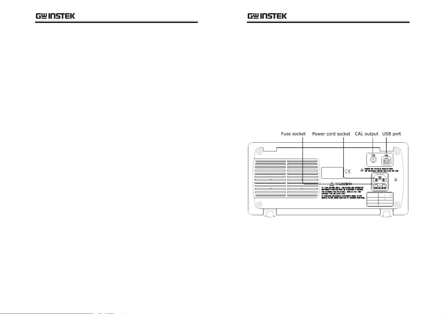
TABLE OF CONTENTS
Table of Contents
GDS-1000 Programming Manual
INTERFACE OVERVIEW ..................................................... 4
Rear Panel Overview .................................. 4
Configuring the USB Interface ................... 5
COMMAND OVERVIEW .................................................... 6
Command Syntax ....................................... 6
List of Command in Functional Order........ 7
List of Command in Alphabetical Order ... 10
COMMAND DETAILS ...................................................... 12
System command .................................... 13
Acquisition Command.............................. 15
Autoset Command ................................... 18
Channel / Math Command....................... 19
Cursor Command..................................... 24
Display Command.................................... 28
Measure command .................................. 31
Save/Recall Command ............................. 16H40
Time (Horizontal) command ................... 17H45
Trigger command..................................... 18H48
INTERFACE OVERVIEW
This manual describes how to use the GDS-1000’s
remote command functionality and lists the
command details. The Overview chapter describes
how to configure the GDS-1000 USB remote
control interface.
0BRear Panel Overview
LI NE VOLTAGE
AC 100 240V
RANGE
FREQUENCY
50 60Hz
FUSE RATI NG
T1A 250V
POWER MAX.
18W 40VA
3
4
Page 3

INTERFACE OVERVIEW
Configuring the USB Interface
USB connection
PC side connector
Type A, host
GDS-1000 Programming Manual
GDS-1000 side
connector
Speed
Panel operation
1. Connect the USB cable to
the USB slave port on the
rear.
2. When the PC asks for the USB driver, select
dso_cdc_1000.inf which is downloadable from
the GW website, www.gwinstek.com.tw
1000 product corner.
3. On the PC, activate a terminal application such
as MTTTY (Multi-Threaded TTY). To check the
COM port No., see the Device Manager in the
PC. For WindowsXP, select Control panel →
System → Hardware tab.
4. Run this query command via the terminal
application.
*idn?
This command should return the manufacturer,
model number, serial number, and firmware
version in the following format.
GW, GDS-1022, 000000001, V1.00
5. Configuring the command interface is
completed. Refer to the other chapters for more
details.
• Page6: list of commands and command syntax
• Page12: details of each command
Type B, slave
1.1/2.0 (full speed)
, GDS-
COMMAND OVERVIEW
The Command overview chapter lists all GDS1000 commands in functional order as well as
alphabetical order. The command syntax section
shows you the basic rules you have to apply when
using commands.
Command Syntax
Compatible
standard
Command format
Parameter Type Description Example
<Boolean>
<NR1>
<NR2>
<NR3>
<NRf>
Message
terminator
LF
<dab>^END
Note
• IEEE488.2, 1992 (fully compatible)
• SCPI, 1994 (partially compatible)
trig:del:mod <NR1>LF
1234
boolean logic 0, 1
integers 0, 1, 2, 3
decimal numbers 0.1, 3.14, 8.5
floating point 4.5e-1, 8.25e+1
any of NR1, 2, 3 1, 1.5, 4.5e-1
LF^END
Commands are non-case sensitive.
line feed code (hexadecimal 0A)
with END message
line feed code
last data byte with END message
1: command header
2: single space
3: parameter
4: message terminator
5
6
 Loading...