


Dual Measurement Multimeter
GDM-9060/9061
USER MANUAL
REV. C
ISO-9001 CERTIFIED MANUFACTURER

This manual contains proprietary information, which is protected by
copyrights. All rights are reserved. No part of this manual may be
photocopied, reproduced or translated to another language without
prior written consent of Good Will company.
The information in this manual was correct at the time of printing.
However, Good Will continues to improve products and reserves the
right to change specifications, equipment, and maintenance
procedures at any time without notice.
Good Will Instrument Co., Ltd.
No. 7-1, Jhongsing Rd., Tucheng Dist., New Taipei City 236, Taiwan (R.O.C.).

Table of Contents
Table of Contents
SAFETY INSTRUCTIONS .................................................... 5
Safety Symbols .................................................................... 5
Safety Guidelines ................................................................. 6
GETTING STARTED .......................................................... 10
Characteristics ..................................................................... 11
Front Panel Overview .......................................................... 13
Rear Panel Overview ............................................................ 18
Status Bar ............................................................................ 21
Set Up.................................................................................. 24
BASIC MEASUREMENT .................................................... 26
Basic Measurement Overview ............................................. 27
AC/DC Voltage Measurement .............................................. 30
AC/DC Current Measurement ............................................. 37
2W/4W Resistance Measurement ........................................ 41
Continuity Test .................................................................... 44
Diode Measurement ............................................................ 47
Frequency/Period Measurement .......................................... 48
Capacitance Measurement .................................................. 53
Temperature Measurement ................................................. 56
DUAL MEASUREMENT .................................................... 66
Dual Measurement .............................................................. 67
ADVANCED MEASUREMENT ........................................... 77
Advanced Measurement Overview ...................................... 78
Relative Value Measurement ............................................... 79
Hold Measurement ............................................................. 81
Trigger Setting ..................................................................... 84
Filter Setting ........................................................................ 90
Math Measurement ............................................................. 93
DIGITAL I/O ................................................................... 117
Digital I/O Overview ........................................................... 118
3

GDM-906X Series User Manual
Application: Compare Mode ............................................... 120
Application: 4094 / User Mode ........................................... 127
Application: External Trigger ............................................... 135
SYSTEM & FIRMWARE ................................................... 137
View System Info ................................................................ 138
Firmware Update ................................................................ 139
MENU SETTING ............................................................. 141
Configure System ............................................................... 142
Configure Display ............................................................... 160
SCREENSHOT & LOG .................................................... 179
Capture ............................................................................... 180
Save Reading ...................................................................... 183
DISPLAY SETTING .......................................................... 187
Digit .................................................................................... 188
Display ................................................................................ 190
REMOTE CONTROL ....................................................... 209
Configure Interface ............................................................. 210
Web Control Interface ......................................................... 243
Command Syntax ................................................................ 248
Command Set ..................................................................... 251
Status system ..................................................................... 337
APPENDIX ...................................................................... 341
Fuse Replacement ............................................................... 342
Battery Replacement ........................................................... 346
Factory Default Parameters ................................................ 348
Specifications ..................................................................... 352
GDM-9061 Section ............................................................. 353
GDM-9060 Section ............................................................. 364
Declaration of Conformity .................................................. 376
INDEX ............................................................................ 377
4

SAFETY INSTRUCTIONS
WARNING
Warning: Identifies conditions or practices that could
result in injury or loss of life.
CAUTION
Caution: Identifies conditions or practices that could
result in damage to the GDM-9060/9061 or to other
property.
DANGER High Voltage
Attention Refer to the Manual
Protective Conductor Terminal
Earth (ground) Terminal
Do not dispose electronic equipment as unsorted
municipal waste. Please use a separate collection facility
or contact the supplier from which this instrument was
purchased.
SAFETY INSTRUCTIONS
This chapter contains important safety instructions that
you must follow when operating the GDM-9060/9061
and when keeping it in storage. Read the following
before any operation to insure your safety and to keep
the GDM-9060/9061 in the best possible condition.
Safety Symbols
These safety symbols may appear in this manual or on the GDM-9060/9061.
5

GDM-906X Series User Manual
General Guideline
CAUTION
Make sure that the voltage input level does not exceed
DC1000V/AC750V.
Make sure the current input level does not exceed 10A.
Do not place any heavy object on the instrument.
Avoid severe impact or rough handling that can lead to
damaging the instrument.
Do not discharge static electricity to the instrument.
Use only mating connectors, not bare wires, for the
terminals.
Do not block or obstruct the cooling fan vent opening.
Do not perform measurement at the source of a
low-voltage installation or at building installations
(Note below).
Do not disassemble the instrument unless you are
qualified as service personnel.
Make sure that the Sense LO terminal to Input LO is
limited to 2Vpk, the Sense HI to Sense LO terminals
are limited to 200Vpk and the Input LO to earth is
limited to 500Vpk.
(Note) EN 61010-1:2010 specifies the measurement categories and
their requirements as follows. The GDM-9060/9061 falls under
category II 300V.
Measurement category IV is for measurement performed at the source
of low-voltage installation.
Measurement category III is for measurement performed in the
building installation.
Measurement category II is for measurement performed on the circuits
directly connected to the low voltage installation.
Power Supply
WARNING
AC Input voltage: 100/120/220/240 V AC ±10%,
50Hz / 60Hz / 400Hz ±10%
The power supply voltage should not fluctuate more
than 10%.
Connect the protective grounding conductor of the
AC power cord to an earth ground, to avoid electrical
shock.
Safety Guidelines
6

SAFETY INSTRUCTIONS
WARNING
(GDM-9061 only)
Due to the fact that the Front/Rear Input Switch on
the front panel is not proposed as an active
multiplexer, do Not change the input switch when
signals are present on either rear or front set of
terminals. Intrument damage and risk of electric shock
may occur if switching the input switch when high
voltage or current is present.
Fuse
WARNING
Fuse type: T0.25A 100/120 VAC
T0.125A 220/240 VAC
Make sure the correct type of fuse is installed before
power up.
To avoid risk of fire, replace the fuse only with the
specified type and rating.
Disconnect the power cord before fuse replacement.
Make sure the cause of a fuse blowout is fixed before
fuse replacement.
Cleaning the
Instrument
Disconnect the power cord before cleaning.
Use a soft cloth dampened in a solution of mild
detergent and water. Do not spray any liquid into the
GDM-9060/9061.
Do not use chemicals or cleaners containing harsh
material such as benzene, toluene, xylene, and acetone.
Operation
Environment
Location: Indoor, no direct sunlight, dust free, almost
non-conductive pollution (Note below)
Temperature: Full accuracy for 0°C to 55°C.
Humidity:
< 30°C: < 80%RH (non-condensing)
30°C~40°C: <70%RH (non-condensing)
>40°C: <50%RH (non-condensing)
Altitude: <2000m
7

GDM-906X Series User Manual
(Note) EN 61010-1:2010 specifies the pollution degrees and their
requirements as follows. The GDM-9060/9061 falls under degree 2.
Pollution refers to “addition of foreign matter, solid, liquid, or
gaseous (ionized gases), that may produce a reduction of dielectric
strength or surface resistivity”.
Pollution degree 1: No pollution or only dry, non-conductive pollution
occurs. The pollution has no influence.
Pollution degree 2: Normally only non-conductive pollution occurs.
Occasionally, however, a temporary conductivity caused by
condensation must be expected.
Pollution degree 3: Conductive pollution occurs, or dry, non-conductive
pollution occurs which becomes conductive due to condensation which
is expected. In such conditions, equipment is normally protected
against exposure to direct sunlight, precipitation, and full wind pressure,
but neither temperature nor humidity is controlled.
Storage
Environment
Location: Indoor
Temperature: −40°C to 70°C
Humidity: <90%RH(non-condensing)
Disposal
Do not dispose this instrument as unsorted municipal
waste. Please use a separate collection facility or contact
the supplier from which this instrument was purchased.
Please make sure discarded electrical waste is properly
recycled to reduce environmental impact.
8

SAFETY INSTRUCTIONS
Green/ Yellow:
Earth
Blue:
Neutral
Brown:
Live (Phase)
Power cord for the United Kingdom
When using the GDM-9060/9061 in the United Kingdom, make sure the
power cord meets the following safety instructions.
NOTE: This lead / appliance must only be wired by competent persons
WARNING: THIS APPLIANCE MUST BE EARTHED
IMPORTANT: The wires in this lead are coloured in accordance with the
following code:
As the colours of the wires in main leads may not correspond with the
coloured marking identified in your plug/appliance, proceed as follows:
The wire which is coloured Green & Yellow must be connected to the Earth
terminal marked with either the letter E, the earth symbol or coloured
Green/Green & Yellow.
The wire which is coloured Blue must be connected to the terminal which is
marked with the letter N or coloured Blue or Black.
The wire which is coloured Brown must be connected to the terminal marked
with the letter L or P or coloured Brown or Red.
If in doubt, consult the instructions provided with the equipment or contact
the supplier.
This cable/appliance should be protected by a suitably rated and approved
HBC mains fuse: refer to the rating information on the equipment and/or
user instructions for details. As a guide, a cable of 0.75mm2 should be
protected by a 3A or 5A fuse. Larger conductors would normally require 13A
types, depending on the connection method used.
Any exposed wiring from a cable, plug or connection that is engaged in a live
socket is extremely hazardous. If a cable or plug is deemed hazardous, turn
off the mains power and remove the cable, any fuses and fuse assemblies. All
hazardous wiring must be immediately destroyed and replaced in accordance
to the above standard.
9

GDM-906X Series User Manual
GETTING STARTED
This chapter describes the GDM-9060/9061 in a nutshell,
including an Overview of its main features and front /
rear panel introduction. After going through the
Overview, follow the Power-up sequence to properly
setup the GDM-9060/9061.
Please note the information in this manual was correct at
the time of printing. However as GW Instek continues to
improve its products, changes can occur at any time
without notice. Please see the GW Instek website for the
latest information and content.
Characteristics .................................................................... 11
Accessories ............................................................................... 12
Front Panel Overview .......................................................... 13
Measurement Keys (basic) ........................................................ 15
Measurement Keys (advanced) ................................................. 17
Rear Panel Overview ........................................................... 18
Status Bar ........................................................................... 21
Set Up ................................................................................. 24
Horizontal/Tilt/Vertical Applications ........................................ 24
Power Up .................................................................................. 25
10

GETTING STARTED
Performance
The highest DCV accuracy:
GDM-9061: 35ppm
GDM-9060: 75ppm
The highest current:
GDM-9061: 10A
GDM-9060: 3A
The highest voltage: 1000V
The highest ACV frequency response: 300 kHz
The fastest sampling rate:
1k Readings/sec (GDM-9060)
10k Readings/sec (GDM-9061)
Internal memory:
10k read memory (GDM-9060)
100k read memory (GDM-9061)
Data Logging to USB
Features
6
2
1
digits
Multi functions: ACV, DCV, ACI, DCI, 2W/4W R, Hz,
Temp, Continuity, Diode, Period, Capacitance test,
REL, dBm, Hold, MX+B, 1/X, REF%, dB, Compare
and Statistics.
Manual or Auto ranging
AC true RMS
Built-in DC Ratio function
Standard SCPI command set in emulation compatible
with Agilent 34401A
Up to 3 temerature measurements: RTD, Thermistor
and Thermocouples (Cold-Junction Compensation)
Graph Display: BarMeter, TrendChart, Histogram
Interface
USB device/RS232/GPIB(optional)/LAN for remote
control
9-pin Digital I/O port
USB device port supports USBCDC and USBTMC
USB Host
Software
Excel Addins
DMM-VIEWER2
Characteristics
The GDM-9060/9061 is a portable, dual-display digital
multimeter suitable for a wide range of applications, such
as production testing, research, and field verification.
11

GDM-906X Series User Manual
Standard
Accessories
Part number
Description
CD-ROM
UM, Software, Driver
82DM-90610M01
Safety Instruction Sheet
GTL-217
Test leads
GTL-246
USB Cable, USB 2.0, A-B type, 1200mm
Optional
Accessories
Part number
Description
11DM-90610101
GDM-9060/9061 GPIB Card
GTL-234
RS-232 Cable , 2000mm
GTL-205A
Temperature Probe Adapter with Thermal
Coupling (K-type)
GTL-308
4W+Shield Test leads, 1.5M
GDM-TL1
Test leads with sharp probe and SMT
grabber with miniature grabber accessory
Accessories
12

GETTING STARTED
1
2
3
4
5 8 7 0 A B
6 9 C D
Item
Description
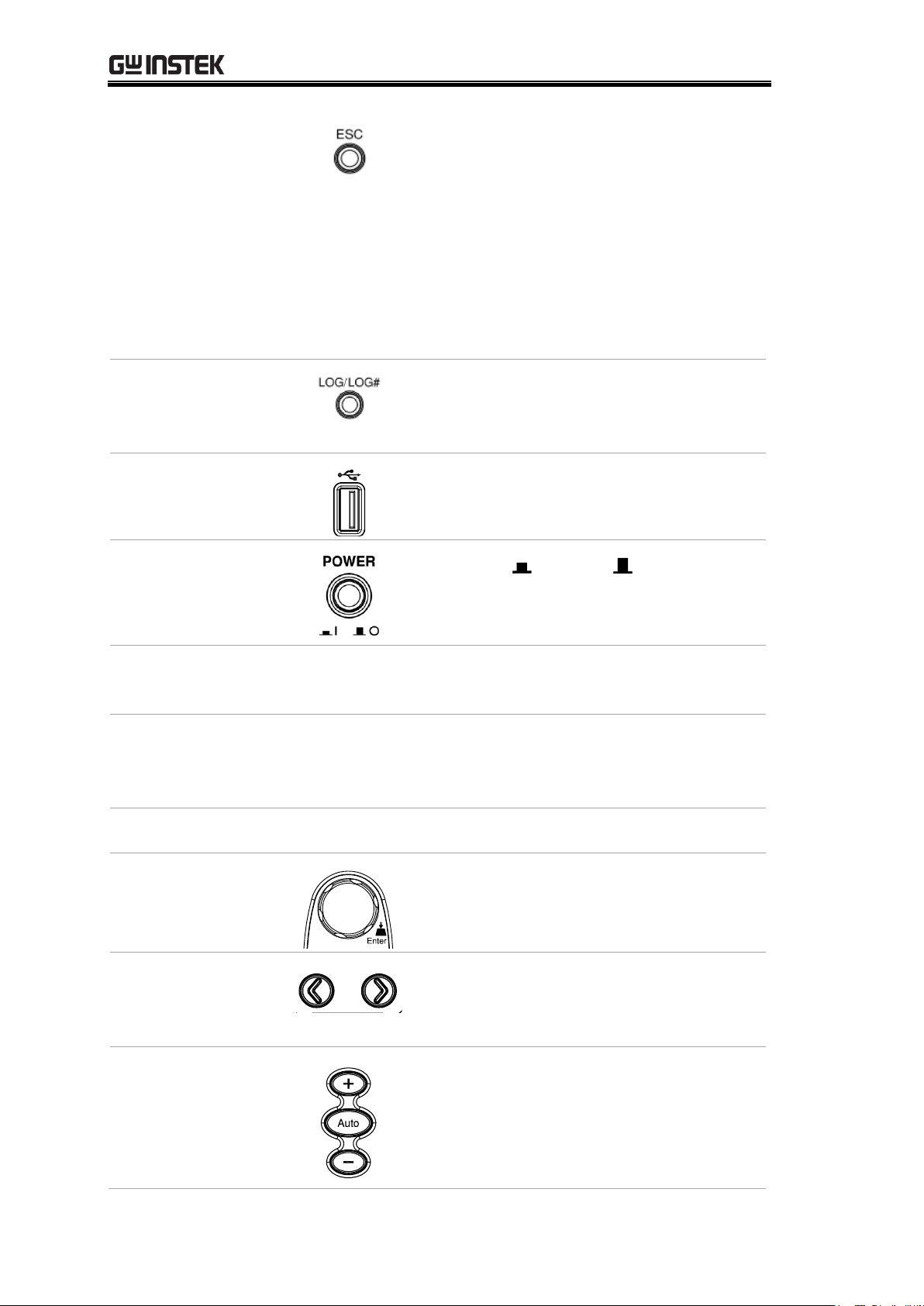
1
ESC (Escape) Key
2
Print screen / Data log Key
3
USB Host Port
4
Power Switch
5
Main Display
6
Function keys (F1 through F6, functions vary per modes)
7
Knob key
8
Arrow Keys
9
Measurement Keys
0
Range Selection Keys
A
HI and LO Sense Terminals
B
HI and LO Input Terminals
C
AC/DC Current Input Terminals (10 A terminal available on
GDM-9061 only)
D
Front/Rear Input Switch (GDM-9061 only)
Front Panel Overview
13
GDM-906X Series User Manual
ESC (Escape) Key
Single press to escape from current page.
Presses and holds the ESC key for 2
seconds to toggle between full display
and simple display, which conceals the
status bar, math display as well as
additional info for lightweight use.
Refer to page 21, page 167 and page 175
for more details of status bar, math
display and additional info, respectively.
Screenshot / Data
Log Saving Key
Captures the current screenshot or saves
the data log for reading. For details, refer
to page 179.
USB Host Port
Connects with USB flash drive for data
storage.
Power Switch
Turns On or Off the main
power. For the power up sequence, see
page 25.
Main Display
The 4.3”TFT LCD shows measurement results and
parameters. For display configurations, see page 160.
Measurement
Keys
There are 4 rows in total of both basic and advanced
measurement keys deployed on the front panel. For the
details, refer to page 15 and page 17.
Function Keys
The 6 keys have varied functions per different settings.
Knob Key
Scrolls the knob to select parameters in
various setting pages. Press the key until
click to confirm setting.
Arrow Keys
Presses the left or right arrow keys to
move parameter cursor rightward or
leftward per requirement.
Range Selection
Keys
Presses the Auto key to activate
auto-range mode, whilst clicking “+” or
“–“ key can increase or decrease range
parameter, respectively.
14

GETTING STARTED
DC/AC 3A
Terminal
DC/AC current input
DC: 100μA~3A
AC: 100μA~3A
For details see page 37.
For the fuse replacement procedure, see
page 343.
Sense LO
Terminal
Accepts LO sense line in 4W resistance
measurement. For details, see page 41.
Sense HI
Terminal
Accepts HI sense line in 4W resistance
measurement. For details, see page 41.
Input LO
Terminal
Accepts ground (COM) line in all
measurements except the sense line in
4W Resistance (page 41).
The maximum withstand voltage
between this terminal and earth is
500Vpk.
Input HI
Terminal
Used as an input port for all
measurements except for DC/AC
Current measurements.
DC/AC 10A
Terminal
(GDM-9061 only)
Accepts DC/AC Current input.
For DCI or ACI details, see page 37.
Background
The upper 2 rows of measurement keys are used for
basic GDM-9060/9061 measurements such as voltage,
current, resistance, continuity, diode, frequency, period,
capacitance and temperature. Each key has a primary
and secondary function individually. The secondary
function is accessed in conjunction with the Shift key.
Measurement Keys (basic)
15

GDM-906X Series User Manual
Shift
The Shift key is used to select the
secondary functions assigned to each
front panel key. When pressed, the
Shift indicator appears in the display.
Local
For the Local key, it helps release
from the remote control and
returns the instrument to local
panel operation (page 210).
ACV
Measures AC Voltage (page 30).
Shift → ACV (ACI)
Measures AC Current (page 37).
DCV
Measures DC Voltage (page 30).
Shift → DCV (DCI)
Measures DC Current (page 37).
Ω2W (Resistance)
Measures 2-wire Resistance (page
41).
Shift → Ω2W (Ω4W
Resistance)
Measures 4-wire Resistance (page
41 ).
(Continuity)
Tests Continuity (page 44).
Shift →
(Diode )
Tests Diode (page 47).
FREQ (Frequency)
Measures Frequency (page 48).
Shift + FREQ
(Capacitance )
Measures Capacitance (page 53).
TEMP
(Temperature)
Measures Temperature (page 56).
16

GETTING STARTED
Background
The lower 2 rows of measurement keys are used for
more advanced functions. Each key has a primary and
secondary function. The secondary function is accessed
in conjunction with the Shift key.
REL
Measures the Relative value (page
79).
Shift → REL
(REL#)
Manually sets the reference value for
the Relative value measurement
(page 79).
Hold
Activates the Hold function (page
81).
Shift → Hold
(Hold#)
Manually sets the parameters for the
Hold measurement (page 81).
TRIG (Trigger)
Activates the Trigger function (page
84).
Shift → TRIG
(TRIG#)
Manually sets the parameters for the
Trigger function (page 84).
Menu
Enters the setting pages in various
Menus (page 142).
Shift → Menu
(Filter)
Manually sets the parameters for the
Filter function (page 90).
DISP
Display settings (page 187).
Shift → DISP
(Math)
The Math functions including dB,
dBm, Compare, MX+B, 1/X and
Percent manually (page 93).
Measurement Keys (advanced)
17

GDM-906X Series User Manual
1
240
2 5 9 0 A
4 3 6 7 8 B
Item
Description
1
HI and LO Sense Terminals (GDM-9061 only)
2
HI and LO Input Terminals (GDM-9061 only)
3
3 A Current Terminal (GDM-9061 only)
4
3 A Current Terminal Fuse
5
DIGITAL I/O Connector
6
RS-232 Interface Connector
7
USB Interface Connector (B Type)
8
Ethernet (LAN) Connector
9
Fan Vents
0
AC Mains Input (Power Cord Socket)
A
AC Mains Line Voltage Selector and Fuse Socket
B
GPIB Connector (optional)
Rear Panel Overview
18

GETTING STARTED
Power Cord Socket
Accepts the power cord. AC
100/120/220/240V ±10%,
50Hz / 60Hz /400Hz ±10%.
For power on sequence, see page
25.
Fuse Socket
Holds the main fuse:
100/120 VAC: T0.25A
220/240 VAC: T0.125A
For fuse replacement details, see
page 342.
RS-232C port
Accepts an RS-232C cable for
remote control; DB-9 male
connector.
For remote control details, see
page 214.
USB device port
Accepts a USB device cable for
remote control; Type B, female
connector.
For remote control details, see
page 211.
LAN port
Accepts a LAN for remote
control;
For remote control details, see
page 227.
Digital I/O port
Accepts a digital I/O cable for the
Hi/Lo limit tests; DB-9 pin,
female connector.
For digital I/O details, see page
117.
Optional GPIB port
Accepts an optional GPIB card.
For GPIB details, see page 223.
19

GDM-906X Series User Manual
Fan Vents
For heat ventilation when machine
is under operation.
Sense LO Terminal
(GDM-9061 only)
Accepts LO sense line in 4W
resistance measurement. For
details, see page 41.
Sense HI Terminal
(GDM-9061 only)
Accepts HI sense line in 4W
resistance measurement. For
details, see page 41.
Input LO Terminal
(GDM-9061 only)
Accepts ground (COM) line in all
measurements except the sense
line in 4W Resistance (page 41).
The maximum withstand voltage
between this terminal and earth is
500Vpk.
Input HI
Terminal
(GDM-9061 only)
Used as an input port for all
measurements except for DC/AC
Current measurements.
DC/AC 3A Terminal
(GDM-9061 only)
DC/AC current input
DC: 100μA~3A
AC: 100μA~3A
For details see page 37.
DC/AC 3.15A Input
Current Fuse
Holds the current fuse: T3.15A,
500V , 5*20mm
For fuse replacement details, see
page 343.
20

GETTING STARTED
Background
Identify each icon within the top status bar.
Status Bar
Display
1 2 3 4 5 6 7 8 9 0
A
Item
Description
1
Local/Remote control icon
2
RS-232/USB-CDC/USB-TMC/LAN/GPIB interface icon
3
Error icon for commands from remote control
4
Rear panel switch icon
5
Shift key identification icon
6
The first and second function menu switch icon
7
Digital I/O mode icon (User/4094)
8
USB flash drive connection icon
9
Beep/Key Sound setting icon
0
Internet connection status icon
A
Time display
Status Bar
21

GDM-906X Series User Manual
Local Control
It indicates the unit is under local
control mode.
Remote Control
It indicates the unit is under remote
control. Refer to page 209 for details.
RS-232
It indicates RS-232 interface is activated.
Refer to page 214 for details.
USB - CDC
It indicates USB - CDC interface is
activated. Refer to page 214 for details.
USB - TMC
It indicates USB - TMC interface is
activated. Refer to page 214 for details.
LAN
It indicates LAN interface is activated.
Refer to page 227 for details.
GPIB
It indicates GPIB interface is activated.
Refer to page 223 for details.
ERROR
It indicates error occurs in commands.
To erase the error icon, it is required to
read or sweep the error by remote
control commands or reboot action.
Refer to page 323 for details.
Rear Panel
It indicates rear panel control. When the
icon appears, only rear panel is available;
otherwise, use front panel for
measurement. Refer to page 18 for details.
Shift
It indicates the shift key is being pressed
ready for in conjunction with other keys
for additional functions. Refer to page
15 for details.
First function
menu
It indicates the active bottom menu
corresponding to function keys is the
first menu. Click the Knob key (Enter)
to switch to the second function menu.
22

GETTING STARTED
Second function
menu
It indicates the active bottom menu
corresponding to functional keys is the
second menu. Click the Knob key (Enter)
to switch to the first function menu.
Digital I/O –
4094 mode
It indicates Digital I/O – 4094 mode is
enabled. Refer to page 127 for details.
Digital I/O –
User mode
It indicates Digital I/O – User mode is
enabled. Refer to page 127 for details.
Flash Drive –
Capture
It indicates the Capture mode is ready
for the connected flash drive. Refer to
the page 179 for details of Capture.
Flash Drive –
Save Reading
It indicates the Save Reading mode is
ready for the connected flash drive. Refer
to page 183 for details of Save Reading.
Flash Drive –
Failure
It indicates something error occurs and
thus flash drive fails to connect to unit.
Sound – Beep
It indicates sound of beep is enabled.
Refer to page 142 for details.
Sound - Key
It indicates sound of key is enabled.
Refer to page 143 for details.
Sound – All
It indicates sounds of beep and key are
both enabled.
Sound – Off
It indicates sounds of beep and key are
both disabled.
Internet On
It indicates internet connection is
established. Refer to page 227 for details.
Internet Off
It indicates internet connection is Not
well established.
Time Display
It indicates the time display. For detailed
setting, refer to page 145.
23

GDM-906X Series User Manual
Pull out the handle sideways and rotate it clockwise for the applications below.
Horizontal
Tilt
Place the unit horizontally.
Rotate the handle for tilt stand.
Vertical
Place the handle vertically for hand carry.
Set Up
Horizontal/Tilt/Vertical Applications
24

Power Up
Steps
1. Ensure the correct line voltage is
clearly shown on the fuse socket
(240V in the right figure for
example). If not, see page 342 to
set the proper line voltage and fuse.
2. Connect the power
cord to the AC
Voltage input.
Note
Make sure the ground connector on the power cord is
connected to a safety ground. This will affect the
measurement accuracy.
3. Push the power button
until click to turn on the
main power switch on
the front panel.
4. The screen firstly shows the logo brand of
GWINSTEK followed by the message “Load the
default parameter” indicating default parameter is loaded
in the initial startup.
GETTING STARTED
25

GDM-906X Series User Manual
BASIC MEASUREMENT
Basic Measurement Overview ............................................ 27
Refresh Rate .............................................................................. 27
Automatic (Internal)/Single Triggering ..................................... 29
AC/DC Voltage Measurement ............................................. 30
Select Voltage Range ................................................................. 31
General Voltage Setting ............................................................. 32
Voltage Conversion Table .......................................................... 35
Crest Factor Table ...................................................................... 36
AC/DC Current Measurement ............................................ 37
Select Current Range ................................................................. 39
General Current Setting ............................................................ 40
2W/4W Resistance Measurement ....................................... 41
Select Resistance Range ............................................................ 42
General Resistance Setting ....................................................... 43
Continuity Test .................................................................... 44
Set Continuity Threshold ........................................................... 45
Diode Measurement ........................................................... 47
Frequency/Period Measurement ......................................... 48
Frequency/Period In-Depth Setting ........................................... 51
Capacitance Measurement ................................................. 53
Cable Open Function ................................................................. 54
Select Capacitance Range .......................................................... 55
Temperature Measurement ................................................. 56
General Temperature Setting .................................................... 57
Thermocouple Sensor Type ....................................................... 58
Reference Junction Temperature (SIM Temperature) ................ 58
Thermocouple Setting ............................................................... 59
RTD 2W/4W Setting .................................................................. 60
Set User Type of RTD 2W/4W .................................................... 61
Thermistor 2W/4W Setting ....................................................... 63
Set User Type of Thermistor 2W/4W ......................................... 64
26

BASIC MEASUREMENT
Background
Basic measurement refers to the several types of measurements
assigned to the upper 2 row keys on the front panel.
Measurement
type
ACV
AC Voltage
DCV
DC Voltage
ACI
AC Current
DCI
DC Current
Ω 2W/ Ω 4W
2-wire and 4-wire Resistance
Continuity/Diode
FREQ
Frequency/Capacitance
TEMP
Temperature
Advanced
measurement
Advanced measurement (page 75) mainly refers to the
operation using the result obtained from one or more of the
basic measurements.
Background
Refresh rate defines how frequently the GDM-9060/9061
captures and updates measurement data. A faster refresh rate
yields a lower accuracy and resolution. A slower refresh rate
yields a higher accuracy and resolution. Consider these
tradeoffs when selecting the refresh rate.
Measurement Type
Refresh Rate Available
DCV/DCI/ 2W/4W
5/s
20/s
60/s
100/s
400/s
1k/s*1
1.2k/s*2
2.4k/s*2
4.8k/s*2
7.2k/s*2
10k/s*2
ACV/ACI
1/s
5/s
20/s
Continuity / Diode
60/s
100/s
400/s
Frequency & Period
1s
100ms
10ms
Capacitance
2/s
Temperature
5/s
20/s
60/s
Note
*1
is applicable to GDM-9060, whilst *2 is specifically for GDM-9061.
Basic Measurement Overview
Refresh Rate
27
GDM-906X Series User Manual
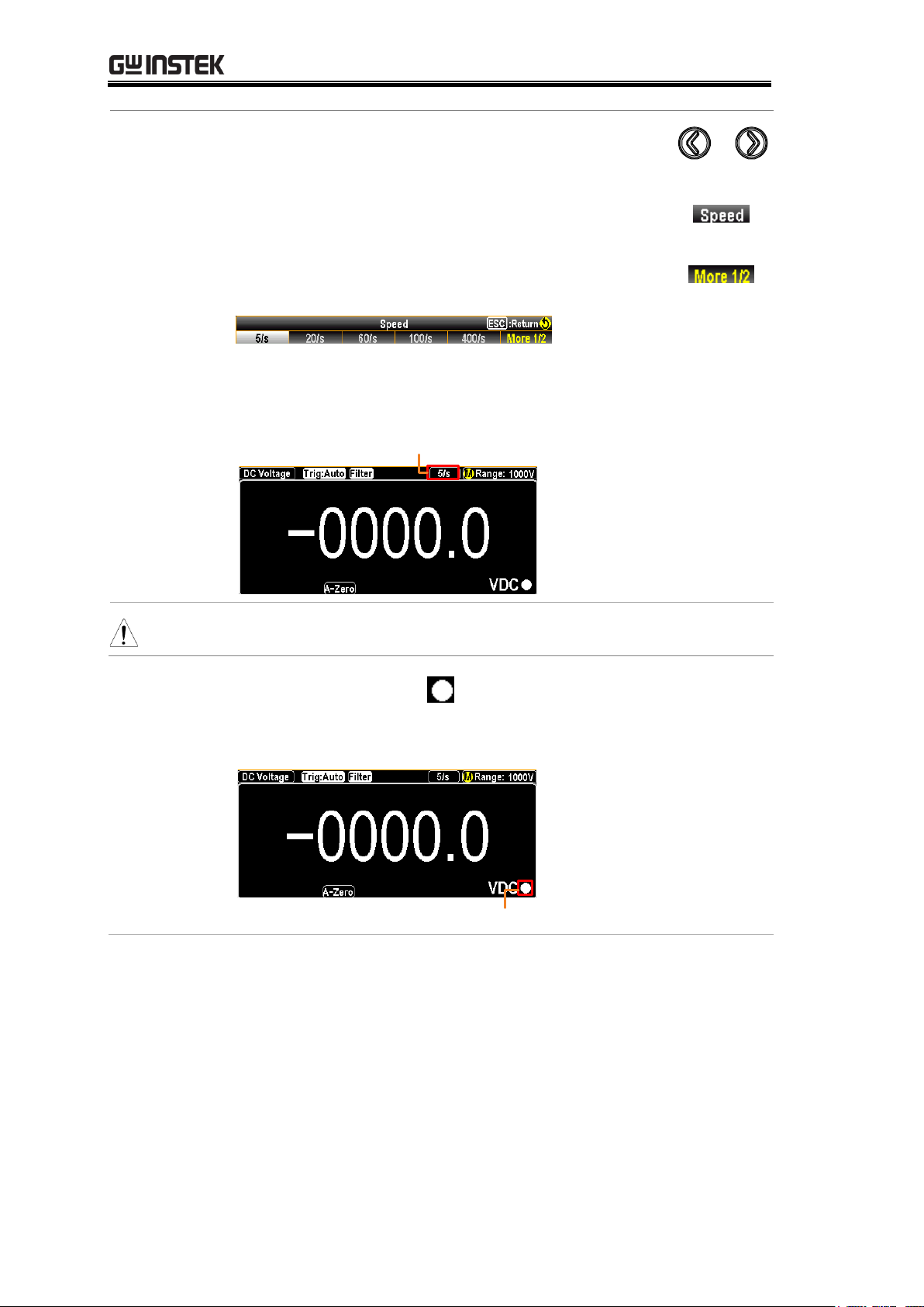
Selection
Procedure
Press the left or right arrow keys to change the
refresh rate.
You can also press the F2 (Speed) key to select a
desired rate for measurement. Press corresponding
function key in accord with the desired option on
screen display. Also, the F6 (More ½) key shows
when available options are more than single page.
The refresh rate will be shown at the upper right
corner of the display. See the example below.
Active Refresh Rate
Note
The refresh rate cannot be set for capacitance measurement.
Reading
indicator
The reading indicator , which is located in the lower-right
corner of display, flashes according to the defined refresh rate
setting.
Reading Indicator
28

BASIC MEASUREMENT
Overview
By default, the GDM-9060/9061 automatically triggers
according to the refresh rate. See the previous page for refresh
rate setting details. The TRIG key, on the other hand, is used to
manually trigger once per click.
Single Trigger
Simply press the TRIG key to Single trigger
measurement. Pressing once stands for trigger for
single time. See the figure below for example.
Indicator Single Trigger Mode
Automatic
(Internal)
Trigger
Press and hold the TRIG key for 2 seconds to
return to the Automatic (Internal) Trigger.
Indicator Auto (Internal)
Trigger Mode
(Press & hold
for 2 seconds)
Note
Single triggering is not supported for capacitance
measurements.
Automatic (Internal)/Single Triggering
29

GDM-906X Series User Manual
Voltage type
AC
0 ~ 750V
DC
0 ~ 1000V
Activate ACV/
DCV
Press the ACV key or DCV key to
measure AC or DC voltage,
respectively.
or
ACV/DCV mode
display appears
The mode will switch to ACV, DCV mode immediately.
See the figure below for example.
DC or AC Voltage
Indicates DC or AC Voltage mode
5/s
Indicates the active refresh rate
Indicates Automatic range selection
Range: 100mV
Indicates the available range of Voltage
+000.1066 mVDC
Indicates the exact measured value
Connect the test
lead and measure
Connect the test lead between the
Input HI and Input LO terminals.
The display updates the reading.
AC/DC Voltage Measurement
30
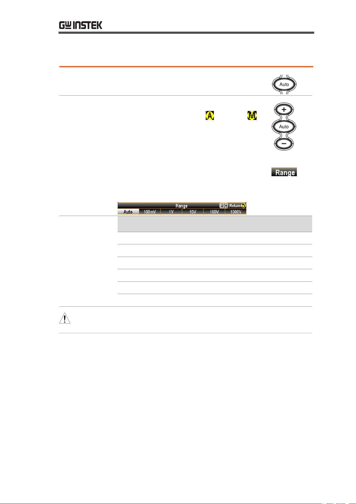
BASIC MEASUREMENT
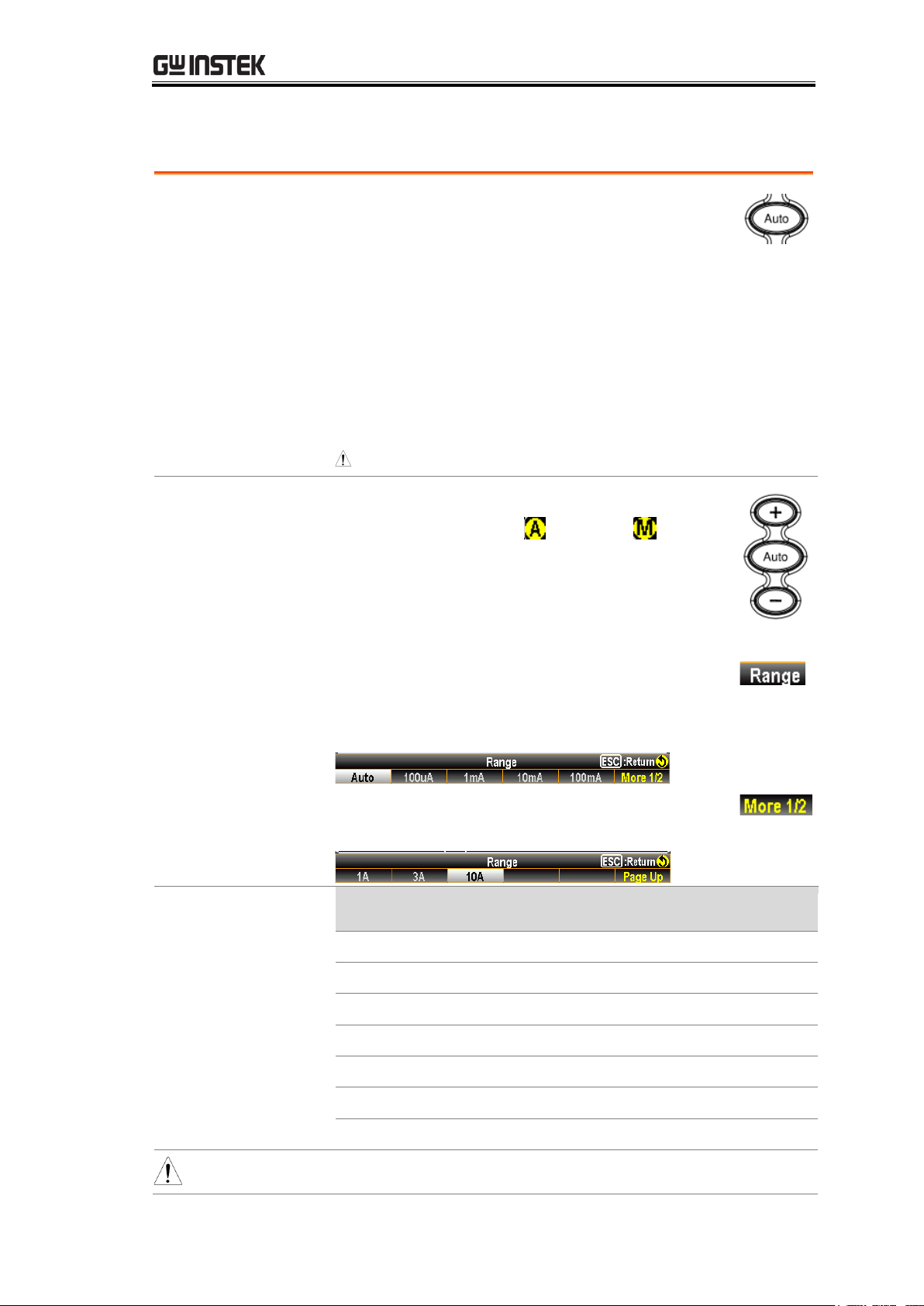
Auto range
To turn the automatic range selection
On/Off, press the Auto key.
Manual range
Press the “+” or the “-” key to select the
range. The Auto indicator turns to
indicating Manual range selection.
If the appropriate range is unknown,
select the highest range.
You can also press the F1 (Range) key to
select a range for the measurement.
Press the F1 ~ F6 key to select a desired
range for the voltage measurement.
Selection list
Range
Resolution
Full scale
100mV
0.1μV
119.9999mV
1V
1 μV
1.199999 V
10V
10 μV
11.99999 V
100V
100 μV
119.9999 V
750V (AC)
1mV
787.500 V
1000V (DC)
1mV
1050.000 V
Note
For more detailed parameters, see the specifications on
page 353.
Select Voltage Range
31

GDM-906X Series User Manual
General Voltage Setting
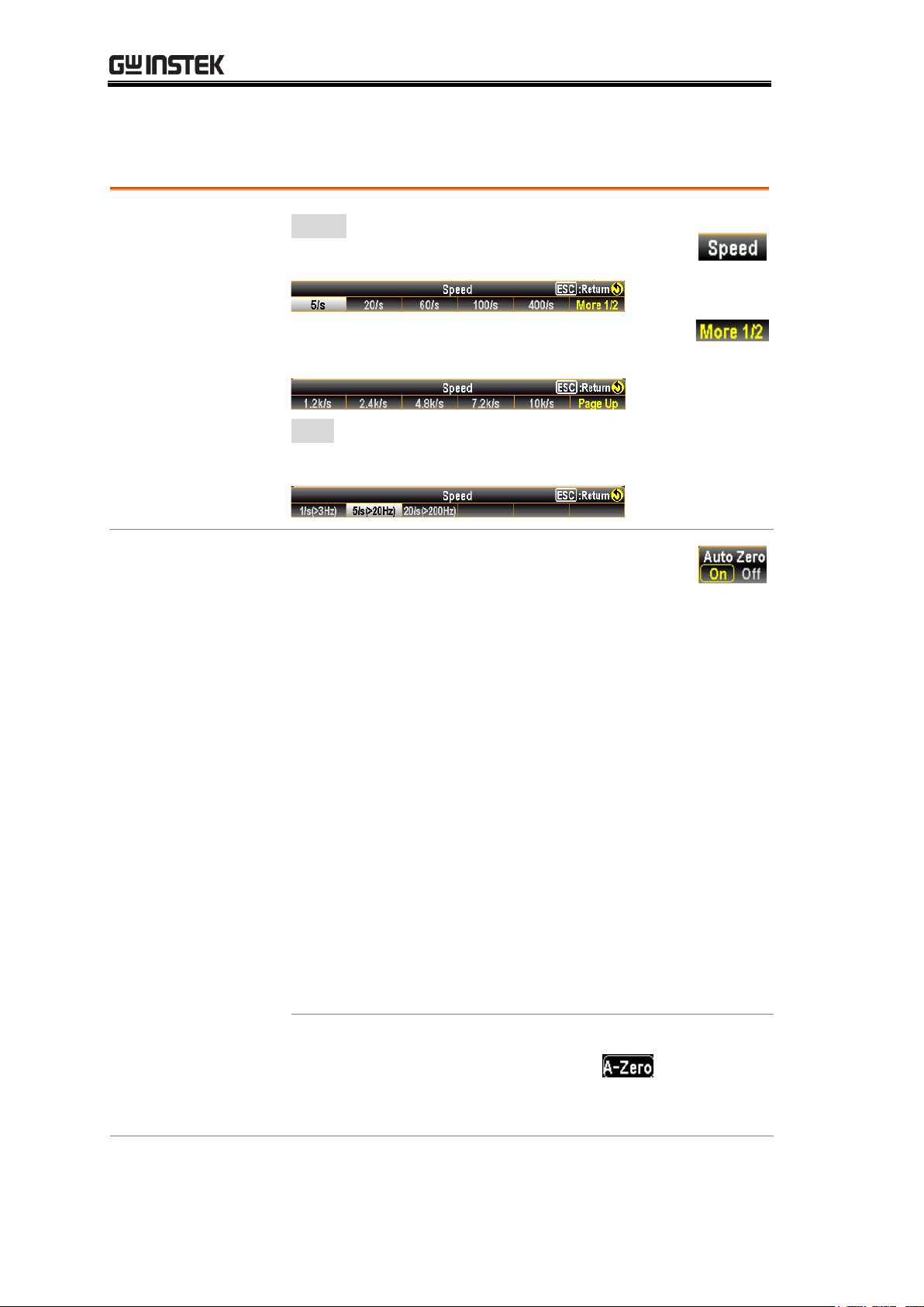
F2 (Speed) key
to select refresh
rate
DCV:
Press the F1 ~ F5 key to select the desired rate
Press the F6 (More 1/2) key for next page with
more options as the figure shown below.
ACV:
Press the F1 ~ F3 key to select the desired rate
F3 (Auto Zero)
key to enable
Auto Zero (DCV
mode only)
Background
Autozero provides the most
accurate measurements, but requires
additional time to perform the zero
measurement. With autozero
enabled (On), the GDM-9060/9061
internally measures the offset
following each measurement. It then
subtracts that measurement from
the preceding reading. This prevents
offset voltages present on the
GDM-9060/9061’s input circuitry
from affecting measurement
accuracy. With autozero disabled
(Off), the GDM-9060/9061
measures the offset once and
subtracts the offset from all
subsequent measurements.
Display
When turning On the Auto Zero, the display
shows an icon indicating the Auto
Zero mode is currently being activated.
32

BASIC MEASUREMENT
F4 (Input R) key
to select input
resistance
Background
Specify the input impedance to the
test leads (Input R). This specifies
the measurement terminal input
impedance, which is either Auto or
10 MΩ.
The Auto mode selects high
impedance (Hi-Z) for the 100
mV, 1 V and 10 V ranges, and 10
MΩ for the 100 V and 1000 V
ranges. In most situations, 10 MΩ
is high enough to not load most
circuits, but low enough to make
readings stable for high impedance
circuits. It also leads to readings with
less noise than the (Hi-Z) option,
which is included for situations
where the 10 MΩ load is
significant.
Vs = ideal voltage of DUT
Rs = input impedance of DUT
Ri = input impedance of
GDM-9060/9061 (either 10M or
10G available (Hi-Z))
Deviation (%) = Rs/(Rs+Ri) * 100
Display
When “Auto” is selected, the display shows
an icon indicating the Auto mode is
currently being activated.
33

F5 (DCV Ratio)
key to enable
DCV Ratio
Background
The GDM-9060/9061 is able to
calculate DCV ration by measuring
input voltage from the Input
terminals and the reference voltage
from the Sense terminals. Before
activating the DCV Ration, it is
required to wire test leads as the
following illustration.
The equation of DCV ratio is like
the following mathematical
calculation:
See the above equation from which
DC Reference Voltage indicates the
measured voltage from the Sense
terminals.
Display
DCV Ratio
Reading
Input Voltage
Reading
Reference
Voltage Reading
From the screenshot above for example, the
INP: +00.86308V (input voltage) is divided
by the REF: +00.85414V (reference voltage),
and the result turns out the DCV ratio:
+1.010457 shown in giant reading clearly.
GDM-906X Series User Manual
34
BASIC MEASUREMENT
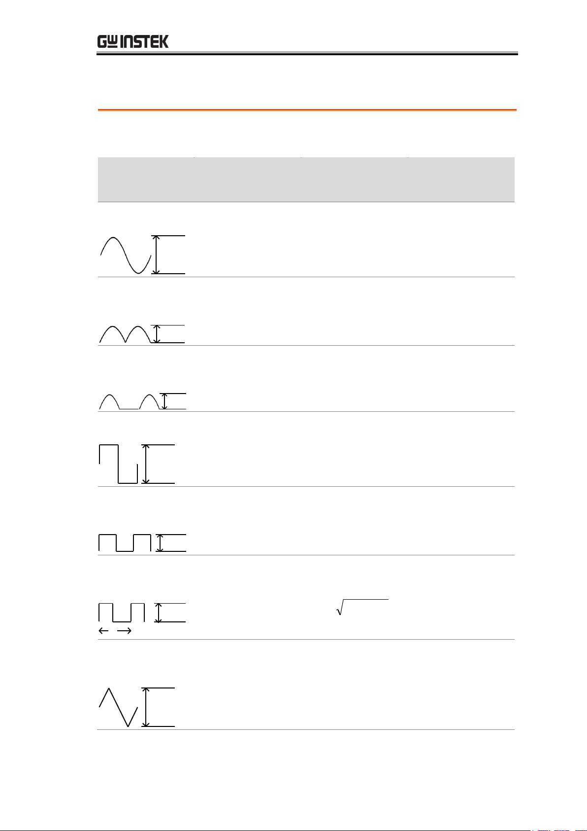
Background
This table shows the relationship between AC and DC
reading in various waveforms.
Waveform
Peak to Peak
AC
(True RMS)
DC
Sine
PK-PK
2.828
1.000
0.000
Rectified Sine
(full wave)
PK-PK
1.414
0.435
0.900
Rectified Sine
(half wave)
PK-PK
2.000
0.771
0.636
Square
PK-PK
2.000
1.000
0.000
Rectified
Square
PK-PK
1.414
0.707
0.707
Rectangular
Pulse
PK-PK
X
Y
2.000
2K
K=
)2
( DD
D=X/Y
2D
D=X/Y
Triangle
Sawtooth
PK-PK
3.464
1.000
0.000
Voltage Conversion Table
35

GDM-906X Series User Manual
Background
Crest factor is the ratio of the peak signal amplitude to the
RMS value of the signal. It determines the accuracy of AC
measurement. If the crest factor is less than 3.0, voltage
measurement will not result in error due to dynamic range
limitations at full scale. If the crest factor is more than 3.0,
it usually indicates an abnormal waveform as seen from the
below table.
Waveform
Shape
Crest factor
Square wave
1.0
Sine wave
1.414
Triangle
sawtooth
1.732
Mixed
frequencies
1.414 ~ 2.0
SCR output
100% ~ 10%
1.414 ~ 3.0
White noise
3.0 ~ 4.0
AC Coupled
pulse train
>3.0
Spike
>9.0
Crest Factor Table
36

BASIC MEASUREMENT
Background
The GDM-9061, with front/rear input terminals, has two
input terminals for current measurement: the 3A terminal
for current less than 3A and a 10A terminal for
measurements up to 10A, which can measure between 3
~ 10A for both AC and DC current. On the other hand,
for the GDM-9060, which has no rear input terminals,
nor 10A terminal, it offers merely a 3A terminal for
current measurement less than 3A.
Current type
GDM-9060
AC/DC 3A
GDM-9061
AC/DC 3A/10A
Activate ACI/ DCI
Measure
Press the Shift → ACV or Shift →
DCV key to measure AC or DC
current, respectively.
+
or
ACI/DCI mode
display appears
The measurement will switch to ACI, DCI mode
immediately. See the figure below for example.
AC or DC Current
Indicates DC or AC Current mode
5/s
Indicates the active refresh rate
Indicates Automatic range selection
Range: 100mA
Indicates the available range of Current
000.03 mAAC
Indicates the exact measured value
AC/DC Current Measurement
37

GDM-906X Series User Manual
Connect the test
lead and measure
Connect the test lead between the
3A terminal and the Input LO
terminal or DC/AC 10A terminal
and the Input LO terminal,
depending on the input current.
The display updates the reading.
For current ≤ 3A use the 3.15A
terminal.
For current up to 12A use the 10A
terminal.
38
BASIC MEASUREMENT
Auto range
To turn the automatic range selection On/Off,
press the AUTO key. The most appropriate
range for the currently used input jack will be
automatically selected. The GDM-9060/9061 is
able to do this by remembering the last manually
selected range and using that information to
determine the smallest current range that the
auto-range function will switch to. When the
current input is switched to another terminal, the
range must be manually set.
Auto Range not allowed on 10A
Manual range
Press the “+” or the “-” key to select the range.
The AUTO indicator turns to
indicating Manual range selection.
If the appropriate range is unknown, select the
highest range.
You can also press F1 (Range) key to select a
range for the measurement.
Press the F1 ~ F5 key to select a desired range
for the measurement.
Press the F6 (More 1/2) key for next page with
more options as the figure shown below.
Selectable Current
Ranges
Range
Resolution
Full scale
INJACK
100µA
0.1nA
119.9999 µA
3A
1mA
1nA
1.199999 mA
3A
10mA
10nA
11.99999 mA
3A
100mA
100nA
119.9999mA
3A
1A
1μA
1.199999 A
3A
3A
1μA
3.150000 A
3A
10A
10μA
10.50000 A
10A
Note
For further details, see the specifications on page 353.
Select Current Range
39
GDM-906X Series User Manual
General Current Setting
F2 (Speed) key to
select the rate
DCI:
Press the F1 ~ F5 key to select the desired rate
Press the F6 (More 1/2) key for next page with
more options as the figure shown below.
ACI:
Press the F1 ~ F3 key to select the desired rate
F3 (Auto Zero) key
to enable Auto Zero
(DCI mode only)
Background
Autozero provides the most
accurate measurements, but
requires additional time to
perform the zero measurement.
With autozero enabled (On), the
GDM-9060/9061 internally
measures the offset following
each measurement. It then
subtracts that measurement from
the preceding reading. This
prevents offset voltages present
on the GDM-9060/9061’s input
circuitry from affecting
measurement accuracy. With
autozero disabled (Off), the
GDM-9060/9061 measures the
offset once and subtracts the
offset from all subsequent
measurements.
Display
When turning On the Auto Zero, the
display shows an icon indicating
the Auto Zero mode is currently being
activated.
40

BASIC MEASUREMENT
Measurement
type
2-wire OHM
Uses the standard Input HI-LO terminals.
Recommended for measuring resistances
larger than 1kΩ.
4-wire OHM
Compensates the test lead effect using the
4W compensation terminals
(SENSE HI/LO terminals), in addition to
the standard Input HI-LO terminals.
Recommended for measuring sensitive
resistances smaller than 1kΩ.
Activate 2W or
4W Measurement
Press the Ω2W key to activate 2W
resistance measurement.
Press the Shift Ω2W key to
activate 4W resistance measurement.
+
2W/4W resistance
mode display
appears
The mode will switch to the selected resistance mode
immediately. Press the Shift Ω2W key on the front
panel as figure shown below.
2 or 4-Wire OHM
Indicates 2W or 4W Resistance mode
5/s
Indicates the active refresh rate
Indicates Automatic range selection
Range: 100 Ω
Indicates the available range of Resistance
000.0651 Ω
Indicates the exact measured value
2W/4W Resistance Measurement
41

GDM-906X Series User Manual
Connect the test
lead and measure
For 2W measurement, connect the test leads between the
Input HI terminal and the LO terminal.
For 4W measurement, connect the test leads between the
Input HI terminal and the LO terminal, as the way to 2W
measurement. Also, connect another sense leads between
the SENSE LO and HI terminals.
Auto range
To turn the automatic range selection On/Off,
press the Auto key.
Manual range
Press the “+” or the “-” key to select the range.
The Auto indicator turns to indicating
Manual range selection. If the appropriate range
is unknown, select the highest range.
You can also press the F1 (Range) key to select a
range for the measurement.
Press the F1 ~ F5 key to select a desired range
for the measurement.
Press the F6 (More 1/2) key for next page with
more options as the figure shown below.
Selectable
Resistance Ranges
Range
Resolution
Full scale
100Ω
0.1mΩ
119.9999Ω
1kΩ
1mΩ
1.199999kΩ
10kΩ
10mΩ
11.99999kΩ
Select Resistance Range
42

BASIC MEASUREMENT
100kΩ
100mΩ
119.9999kΩ
1MΩ
1Ω
1.199999MΩ
10MΩ
10Ω
11.99999MΩ
100MΩ
100Ω
119.9999MΩ
Note
For more details, see the specifications on page 353.
General Resistance Setting
F2 (Speed) key to
select the rate
Press the F1 ~ F5 key to select the desired rate
Press the F6 (More 1/2) key for next page with
more options as the figure shown below.
F3 (AutoZero) key
to enable Auto Zero
Background
Autozero provides the most
accurate measurements, but
requires additional time to
perform the zero measurement.
With autozero enabled (On), the
GDM-9060/9061 internally
measures the offset following
each measurement. It then
subtracts that measurement from
the preceding reading. This
prevents offset voltages present
on the GDM-9060/9061’s input
circuitry from affecting
measurement accuracy. With
autozero disabled (Off), the
GDM-9060/9061 measures the
offset once and subtracts the
offset from all subsequent
measurements.
Display
When turning On the Auto Zero, the
display shows an icon indicating
the Auto Zero mode is currently being
activated.
43
GDM-906X Series User Manual
Background
The continuity test checks that the resistance in the DUT is
low enough to be considered continuous (of a conductive
nature).
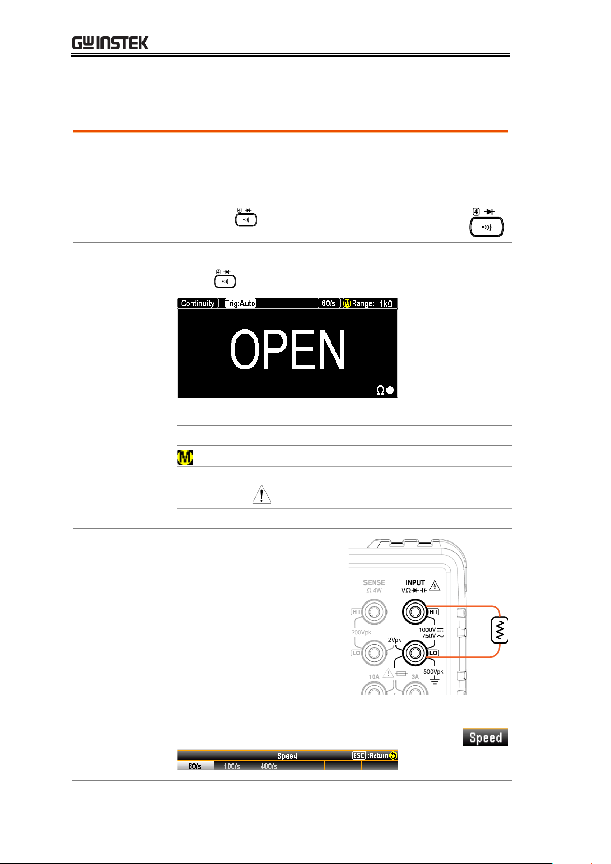
Activate
continuity test
Press the key to activate continuity testing.
Continuity mode
display appears
The mode will switch to continuity testing immediately.
Press on the front panel as figure shown below.
Continuity
Indicates Continuity measurement
60/s
Indicates the active refresh rate
Indicates Manual range selection
1kΩ
Indicates the available range of Continuity
Note: the range selection is fixed in 1kΩ
OPEN Ω
Indicates the currently measured result
Connect the test
lead and measure
Connect the test lead between
the Input HI terminal and the
LO terminal. The display
updates the reading.
F2 (Speed) key to
select the rate.
Press the F1 ~ F3 key to select the desired rate
Continuity Test
44

BASIC MEASUREMENT
F3 (Auto Zero)
key to enable Auto
Zero
Background
Autozero provides the most
accurate measurements, but
requires additional time to
perform the zero measurement.
With autozero enabled (On), the
GDM-9060/9061 internally
measures the offset following each
measurement. It then subtracts
that measurement from the
preceding reading. This prevents
offset voltages present on the
GDM-9060/9061’s input circuitry
from affecting measurement
accuracy. With autozero disabled
(Off), the GDM-9060/9061
measures the offset once and
subtracts the offset from all
subsequent measurements.
Display
When turning On the Auto Zero, the display
shows an icon indicating the Auto
Zero mode is currently being activated.
F4 (BeepVol) key
to select the Vol
Press the F2 ~ F4 key to select the volume level
or press the F1 key to set Beep volume off
Background
The continuity threshold defines the maximum resistance
allowed in the DUT when testing the continuity.
Threshold Range
Threshold
1 to 1000Ω (Default Threshold:10Ω)
Resolution
1Ω
Set Continuity Threshold
45

GDM-906X Series User Manual
Procedure
Press the F5 key to enter the Threshold of
Continuity menu as the figure below shown.
Set the continuity threshold level.
1. Use the Left/Right arrow keys to move cursor
and scroll the Knob key or press Number
keys to enter the desired value.
2. Press the F6 (Enter) key or the Knob key until
click to confirm the threshold settings.
Display
46

BASIC MEASUREMENT
Background
The diode test checks the forward bias characteristics of a
diode by running a constant forward bias current of
approximately 1mA through the DUT.
Activate diode
test
Press the Shift+ key to activate
diode measurement.
+
Diode mode
display appears
The screen will switch to Diode mode immediately as the
figure shown below.
Diode
Indicates the Diode measurement
60/s
Indicates the active refresh rate
Indicates Manual range selection
5V Indicates the available range of Diode
Note: the range selection is fixed in 5V
0.449395 VDC
Indicates the exact measured value
Connect the test
lead and measure
Connect the test lead between
the Input HI terminal and the
LO terminal; Anode-V,
Cathode-COM. The display
updates the reading.
F2 (Speed) key to
select the rate.
Press the F1 ~ F3 key to select the desired rate
Diode Measurement
47

GDM-906X Series User Manual
F3 (Auto Zero)
key to enable Auto
Zero
Background
Autozero provides the most
accurate measurements, but
requires additional time to
perform the zero measurement.
With autozero enabled (On), the
GDM-9060/9061 internally
measures the offset following each
measurement. It then subtracts
that measurement from the
preceding reading. This prevents
offset voltages present on the
GDM-9060/9061’s input circuitry
from affecting measurement
accuracy. With autozero disabled
(Off), the GDM-9060/9061
measures the offset once and
subtracts the offset from all
subsequent measurements.
Display
When turning On the Auto Zero, the display
shows an icon indicating the Auto
Zero mode is currently being activated.
Description
The GDM-9060/9061 can be used to measure the frequency or
period of an input signal.
Range
Frequency
3Hz ~1MHz
Period
1.0μs ~333ms
Activate
frequency or
period test
To measure Frequency, press the FREQ key
followed by clicking the F3 (Measure) key to enter
the Measure menu. Click the F1 (Frequency) key
and the measured frequency will be displayed on
the primary screen with the period value displayed
on the sub section beneath.
Frequency/Period Measurement
48

BASIC MEASUREMENT
To measure Period, press the FREQ key followed
by clicking the F3 (Measure) key to enter the
Measure menu. Click the F2 (Period) key and the
measured period will be displayed on the primary
screen with the frequency value displayed on the
sub section beneath.
Display
Frequency Mode
Indicator Frequency Mode
Period Value in Sub Section
Frequency
Value
Period Mode
Indicator Period Mode
Frequency Value in Sub Section
Period
Value
Frequency
mode display
appears
The mode will switch to the Frequency or Period mode
immediately. Press on the front panel followed by
clicking F3 key to choose Frequency as shown below.
Frequency
Indicates Frequency measurement
100ms
Indicates the active refresh rate
Indicates Manual range selection
49

GDM-906X Series User Manual
100 mV
Indicates the available range of Voltage
59.96609 Hz
Indicates the exactly measured Frequency value
16.67609ms
Indicates the exactly measured Period value
Connection
Depending on different inputs, connect test lead to varied terminals.
In terms of voltage, connect test leads between the Input HI
terminal and the LO terminal. The display updates the reading.
In terms of current, connect test leads between the 3A terminal
and the LO terminal or DC/AC 10A terminal (GDM-9061 only)
and the LO terminal. The display updates the reading.
50

BASIC MEASUREMENT
Background
The input voltage/current range for frequency/period
measurements can be set to Auto range or to manual. By
default, the voltage/current range is set to Auto for both
the period and frequency.
Auto range
Press the Auto/Enter key. Auto will be
displayed on the upper right corner.
F2 (Gate Time) key
to select gate time
Background
It is the threshold to recalculate
frequency/period. Slower the gate time,
e.g., 1s, more accurate the reading value.
Press the F2 key to enter gate time menu. Click
the F1 – F3 key for the desired gate time. See
the figure below with available options.
F4 (InJack) key to
select voltage or
current
Background
In accordance with the target inputs,
choose the corresponding selection per
condition. E.g., select “3A” when the
input current is below 3A amplitude.
Press the F4 (InJack) key to determine whether
the voltage or current 3A or current 10A
(GDM-9061 only) to be measured. Press the F1 –
F3 key to select desired option. See the figure
shown below with options available.
F5 (Time Out) key
to select timeout
Background
It defines the exact value for timeout,
which means measurement will be
suspended after reaching the set timeout
value when none of input is detected.
Frequency/Period In-Depth Setting
51

GDM-906X Series User Manual
Press the F5 key to enter timeout menu. Click
the F1 – F2 key for the desired timeout setting.
See the figure below with available options.
Note: When selecting “Auto”, the timeout
setting will fully sync with the gate time value.
F1 (AC Range) key
to manually select
range setting
Press the “+” or the “-” key to promptly
select the range. The Auto indicator
turns to indicating Manual range
selection. If the appropriate range is
unknown, select the highest range.
You can also press the F1 (AC Range) key to
select a range for the measurement.
Depending on the InJack setting, the
available options vary. See examples below.
When InJack is Voltage:
Press the F1 ~ F6 key to select a desired
range for the measurement.
When InJack is 3A:
Press the F1 ~ F5 key to select a desired
range for the measurement.
Press the F6 (More 1/2) key for next page
with more options as figure shown below.
When InJack is 10A (GDM-9061 only):
Press the F1 ~ F2 key to select a desired
parameter for the measurement.
52

BASIC MEASUREMENT
Background
The capacitance measurement function checks the
capacitance of a component.
Activate
capacitance test
Press the Shift → to activate
capacitance measurement.
+
Capacitance
mode display
appears
The screen will switch to capacitance mode immediately.
Press + on the front panel as shown below.
Capacitance
Indicates the Capacitance measurement
2/s
Indicates the active refresh rate
Note: refresh rate of Capacitance is fixed in 2/s.
Indicates Automatic range selection
Range: 100nF
Indicates the available range of Capacitance
105.0 nF
Indicates the exact measured value
Connect the test
lead and measure
Connect the test lead between
the Input HI terminal and the
LO terminal; Positive-HI,
Negative-LO. The display
updates the reading.
Capacitance Measurement
53

GDM-906X Series User Manual
Background
Cable open function will be activated when capacitance
range is between 1nF and 10nF. It is required to proceed
to Cable Open function when capacitance is between 1nF
and 10nF in which test leads connected will result in
measuring capacity in small scale.
Display
Range 1nF
or 10nF
Cable
Open (F3)
Activate cable open
function
Connect test leads followed by pressing the F3
(Cable Open) key to proceed to Cable Open
function. The measured value will be rectified and
returned to zero as the figure shown below.
Connect the test
lead and measure
Follow the connection method of capacitance
measurement to measure and obtain
precise-prone value.
Note
Except for 1nF/10nF, all are Not applicable to Cable
Open function.
Cable Open Function
54

BASIC MEASUREMENT
Auto range
To turn the automatic range selection On/Off,
press the Auto key.
Manual range
Press the “+” or the “-” key to select the range.
The Auto indicator turns to indicating
Manual range selection. If the appropriate range
is unknown, select the highest range.
You can also press the F1 (Range) key to select a
range for the measurement.
Press the F1 ~ F5 key to select a desired range
for the measurement.
Press the F6 (More 1/2) key for next page with
more options as the figure shown below.
Selectable
Capacitance Ranges
Range
Resolution
Full scale
1nF
1pF
1.199nF
10nF
10pF
11.99nF
100nF
100pF
119.9nF
1μF
1nF
1.199μF
10μF
10nF
11.99μF
100μF
100nF
119.9μF
Note
For further details, please see the specifications on page
363.
Note
The refresh rate settings and the EXT trigger cannot be
used in the capacitance mode.
Select Capacitance Range
55

GDM-906X Series User Manual
Background
The GDM-9060/9061 can measure temperature utilizing
several devices including Thermocouple, RTD
(Resistance Temperature Detector) as well as Thermistor.
To measure temperature, the GDM-9060/9061 accepts a
device input and calculates the temperature from the
voltage fluctuation.
Temperature
Range
Thermocouple
-200°C ~ +1820°C (vary by sensor types)
RTD
-200°C ~ +630°C
Thermistor
-80°C ~ +150°C
Activate
temperature
measurement
Press the TEMP key to activate
temperature measurement.
Temperature mode
display appears
Temperature
Indicates Temperature measurement
+ 0214.552 °C
Indicates the exact measured value
T Couple
Indicates the active Probe
Type R
Indicates the active Type
Connect the test
lead and measure
Connect the sensor lead
between the Input HI
terminal and the LO
terminal. The display
updates the reading.
Temperature Measurement
56

BASIC MEASUREMENT
F2 (Speed) key
to select the rate
Press the F1 ~ F3 key to select the desired rate
F3 (Auto Zero)
key to enable
Auto Zero
Background
Autozero provides the most
accurate measurements, but requires
additional time to perform the zero
measurement. With autozero
enabled (On), the GDM-9060/9061
internally measures the offset
following each measurement. It then
subtracts that measurement from
the preceding reading. This prevents
offset voltages present on the
GDM-9060/9061’s input circuitry
from affecting measurement
accuracy. With autozero disabled
(Off), the GDM-9060/9061
measures the offset once and
subtracts the offset from all
subsequent measurements.
Display
When turning On the Auto Zero, the display
shows an icon indicating the Auto
Zero mode is currently being activated.
F4 (Unit) key to
select unit of
temperature
Press the F4 (Unit) key to enter the Temperature
Unit menu followed by clicking the F1 – F3 key to
choose desired temperature unit. See the figure
shown below.
General Temperature Setting
57

GDM-906X Series User Manual
Background
The GDM-9060/9061 accepts thermocouple inputs and
calculates the temperature from the voltage difference of
two dissimilar metals. Thermocouple sensor type is one
of the main factors to be considered.
Parameter
Thermocouple
Sensor Type
Measurement
Range
Resolution
J
-210 to +1200˚C
0.002 °C
K
-200 to +1372˚C
0.002 °C
N
-200 to +1300˚C
0.003 °C
R
-50 to +1768˚C
0.01 °C
S
-50 to +1768˚C
0.01 °C
T
-200 to +400°C
0.002 °C
B
+250 to +1820˚C
0.01 °C
E
-200 to +1000°C
0.002 °C
Background
(Thermocouple
only)
When a thermocouple is connected to the
GDM-9060/9061, the temperature difference between
the thermocouple lead and the GDM-9060/9061 input
terminal should be taken into account and be cancelled
out; otherwise an erroneous temperature might be added.
The value of the reference junction temperature should
be determined by the user.
Type
Range
Resolution
SIM
(simulated)
-20°C ~ +80°C
0.01°C
The terminal temperature is manually defined by user.
Default value: Auto
Thermocouple Sensor Type
Reference Junction Temperature (SIM Temperature)
58

Procedure
1. Press the F1 (Probe) key to enter the Temperature
Probe menu followed by clicking the F1 (TCouple) key
to activate Thermocouple mode. See the figure
shown below.
2. Press the F5 (Type) key to enter the Sensor Type
menu as the figure shown below. Click the F1 – F5 key to
select a desired sensor type per situations.
3. Press the F6 (More 1/2) key to enter the next
page with more sensor types available for selection.
4. Further press the F6 (Simulated) key after
returning to the previous menu page. You can select either
the default fixed “23.00” or the “Auto” option for the so-called
“Reference Junction Temperature” as following.
When selecting “23.00” by F1 (23.00) key , the display
shows an icon indicating the simulated baseline is 23°C.
If choosing “Auto” by F2 (Auto) key , the subset menu
appears with additional option. Press the F3 (ADJ:+00.00) key
followed by inputting a desired parameter as the following
figure (+10 for example).
5. Press the F6 (Enter) key or the Knob key to
confirm the setting. The icon appears on display
indicating the simulated 34.5 °C, which derives from the input
terminal temperature plus the defined +10 degrees. That is, the
input terminal temperature is 34.5 – 10 = 24.5 °C.
BASIC MEASUREMENT
Thermocouple Setting
59

GDM-906X Series User Manual
Background
The GDM-9060/9061 supports 2 or 4 wire RTD. It is
important to specify the type of temperature sensor used.
Parameter
RTD type
Range
Resolution
All (based on PT100)
-200~630°C
0.001°C
Procedure
1. Press the F1 (Probe) key to enter the Temperature
Probe menu followed by clicking either the F2 (RTD 2W)
or F3 (RTD 4W) key to activate RTD
2W/4W mode. See the figure shown below.
2. Press the F5 (Type) key to enter the Sensor Type menu
as the figure shown below. Click the F1 – F5 key to select a
desired sensor type per your requirement.
3. The display shows the latest setting. See the example of the
figure below where RTD 2W: PT100 is currently activated by
user.
Probe: RTD 2W
Type: PT100
Temperature
Measurement
R0 Value
RTD 2W/4W Setting
60

BASIC MEASUREMENT
Background
The User Type allows any customized RTD sensor coefficients
to be used. The User Type is available for user to configure the
alpha, beta, delta and R0 coefficients individually, as defined by
the Callendar–Van Dusen equation.
Type
Coefficient
Alpha (α)
Beta (β)
Delta (δ)
PT100
0.00385
0.10863
1.49990
D100
0.00392
0.10630
1.49710
F100
0.00390
0.11000
1.49589
PT385
0.00385
0.11100
1.50700
PT3916
0.00392
0.11600
1.50594
Equation
-200°C to 0°C
range
-0°C to 630°C
range
Operate
Procedure
1. Press the F5 (Type) key to enter the Sensor Type
menu followed by pressing the F6 (User) key to
activate User Type.
Set User Type of RTD 2W/4W
61

GDM-906X Series User Manual
2. Press the F6 (User Type) key to enter the User
Type Setup menu where α, β, δ and R0 coefficients can be
set up respectively.
3. Click the F1 (α:0.003850) key to enter the RTD Alpha
Setup page as the figure shown below. Use the Left/Right arrow
keys to move cursor and scroll the Knob key or press
Number keys to enter the desired value.
α default: 0.00385
α range: 0 ~ 9.999999
4. Press the F6 (Enter) key or the Knob key to confirm
the input α value and repeat the previous steps 2 - 4 to set
up the β (Beta), δ (Delta) and R0 coefficients individually.
β default: 00.10863, δ default: 1.49990, R0 default: 100
β, δ range: 0 ~ 9.999999, R0 range: 80 ~ 120
RTD Beta Setup
RTD Delta Setup
RTD R0 Setup
5. After returning to the User Type Setup page, if necessary,
press the F6 (PT100 DEF) key to restore to the
default coefficients’ setting based on the PT100 sensor type.
62

BASIC MEASUREMENT
Background
The GDM-9060/9061 supports 2 or 4 wire Thermistor. It is
important to specify the type of temperature sensor used.
Parameter
Type
Range
Resolution
All
-80~150°C
0.001°C
Procedure
1. Press the F1 (Probe) key to enter the Temperature
Probe menu followed by clicking either the F4 (Therm2W)
or F5 (Therm4W) key to activate
Therm 2W/4W mode. See the figure shown below.
2. Press the F5 (Type) key to enter the Sensor Type
menu as the figure shown below. Click the F1 – F3 key to
select a desired sensor type per your requirement.
3. The display shows the latest setting. See the example of the
figure below where Thermistor 2W: 10kΩ is currently
activated by user.
Probe: Therm2W
Type: 10kΩ
Temperature
Measurement
Thermistor 2W/4W Setting
63

GDM-906X Series User Manual
Background
The User Type allows any customized Thermistor sensor
coefficients to be used. The User Type is available for user to
configure the A, B and C coefficients individually as defined by
the Steinhart–Hart equation.
Type
Coefficient
A B C
2.2k
0.0014733
0.0002372
1.07E-07
5k
0.0012880
0.0002356
9.56E-08
10k
0.0010295
0.0002391
1.57E-07
Equation
Operate
Procedure
1. Press the F5 (Type) key to enter the Sensor Type
menu followed by pressing the F4 (User) key to
activate User Type.
2. Press the F6 (User Type) key to enter the User
Type Setup menu where A, B, and C coefficients can be set up
respectively.
Click the F1 (A:1.2880E-03) key to enter the
THERM A Setup page as the figure shown below. Use the
Left/Right arrow keys to move cursor and scroll the Knob
key or press Number keys to enter the desired value.
A range: 0 ~ 9.9999 (default: 1.2880E-03)
Set User Type of Thermistor 2W/4W
64

BASIC MEASUREMENT
3. Press the F6 (Enter) key or the Knob key to
confirm the input α value and repeat the previous steps 2 - 4
to set up the B and C coefficients individually.
B range: 0 ~ 9.9999 (default :2.35600E-04)
C range: 0 ~ 9.9999 (default :9.55700E-08)
THERM B Setup
THERM C Setup
4. After returning to the User Type Setup page, if necessary,
press the F6 (5 kΩ DEF) key to restore to the
default coefficients’ setting based on the 5 kΩ sensor type.
65

GDM-906X Series User Manual
DUAL MEASUREMENT
Dual Measurement ............................................................. 67
Refresh Rate .............................................................................. 70
Connect the Test Leads ............................................................. 71
The error influence on V+I Dual Measurement ......................... 74
The error of current shunt ......................................................... 75
66

DUAL MEASUREMENT
Background
The dual measurement mode allows you to use the 2nd
display to show another item, thus viewing two different
measurement results at once.
When the multimeter is used in dual measurement mode,
both displays are updated from either a single
measurement or from two separate measurements. If the
primary and secondary measurement modes have the
same range, rate and rely on the same fundamental
measurement, then a single measurement is taken for
both displays; such as ACV and frequency/period
measurements. If the primary and secondary displays use
different measurement functions, ranges or rates, then
separate measurements will be taken for each display. For
example, ACV and DCV measurements.
Most of the basic measurement functions, except for
resistance/continuity/diode/capacitance can be used in
the dual measurement mode.
The following table shows the available measurement
combinations.
Primary Display
Secondary Display
ACV
DCV
ACI
DCI
FREQ
Temp
ACV
X ● ● ● ●
X
DCV
● X ● ● X
●
ACI
● ● X ● ●
X
DCI
● ● ● X X
●
FREQ
● X ● X X
X
Note
When two different measurements are taken, there is a
switching delay between the first measurement and the
second measurement.
Dual Measurement
67

GDM-906X Series User Manual
1st Measurement
item setting
Choose one of the basic
measurement functions from the
table above to set the measurement
mode for the primary display.
For example, press DCV to set the
first display to DCV measurement.
2nd Measurement
item setting
To set a measurement mode for the second display, press
the F6 (2ND) key and the 2ND Function options appear
subsequently.
For example, press the F2 (ACV) key to select ACV
measurement for the second display.
Display
1ST Display
Shows the DCV measurement
2ND Display
Shows the ACV measurement
in orange
Indicates that 1ST display is the
currently active display.
Editing 1st or 2nd
measurement item
settings
After the secondary measurement function has been
activated, the rate, range and measurement item can be
edited for either the primary or secondary display. Note,
however, it is more practical to configure the first or
second measurement items before activating dual
measurement mode.
To edit measurement parameters in dual measurement
mode, you must first set which display is the active
display. The orange outline covering either 1ST or 2ND
icon indicates the active display.
68

DUAL MEASUREMENT
1. Select active
display
Toggle the active display between
the 1ST and 2ND display by
pressing the Knob key:
Primary display: 1ST highlighted in
orange outline.
Secondary display: 2ND highlighted
in orange outline.
Display
1ST in active display:
2ND in active display:
2. Edit active
display settings
Edit the range, rate or measurement
item for the active display in the
same way as for single measurement
operation. See the Basic
Measurement on page 26 for details.
Turn Off 2nd
Measurement
To turn Off the 2ND measurement,
first toggle in 1ST active display
followed by pressing the F6 (2ND)
key. Click the F6 (OFF) key again to
disable the 2ND measurement.
69

Refresh Rate
Background
Refresh rate defines how frequently the
GDM-9060/9061 captures and updates measurement
data. A faster refresh rate yields a lower accuracy and
resolution. A slower refresh rate yields a higher accuracy
and resolution. Consider these tradeoffs when selecting
the refresh rate.
Measurement Type
Refresh Rate
DCV/DCI
5/s
20/s
60/s
100/s
400/s
1k/s*1
1.2k/s*2
2.4k/s*2
4.8k/s*2
7.2k/s*2
10k/s*2
ACV/ACI
1/s
5/s
20/s
Frequency/Period
1s
100ms
10ms
Note
*1
is applicable to GDM-9060, whilst *2 is specifically for GDM-9061.
Selection steps
1. Toggle the active display between the 1ST
and 2ND display by pressing the Knob
key until click.
2. Press the F2 (Speed) key to select a
desired rate for measurement. Press the
corresponding function key (F1 – F5) in
accord with the desired option on screen
display. Also, press the F6 (More 1/2) key
to enter the next page with more options
when available.
3. The refresh rate will be shown at the left
side of each display. See the figure below
shown.
1ST Display
Refresh Rate
2ND Display
Refresh Rate
GDM-906X Series User Manual
70

DUAL MEASUREMENT
Reading
Indicator
The reading indicator flashes according to the defined
refresh rate setting of the active display.
Reading
Indicator
Connect the Test Leads
Connect the test
leads and measure
When using the dual measurement function, the
connection method and number of test leads required
depends on the measurement combination. Use the
connect diagrams below as guide when taking dual
measurements.
Voltage and
Frequency/Period
Measurement
71

GDM-906X Series User Manual
Voltage/Frequency/
Period and Current
Measurement
Note
DC Current measurements will be displayed as a
negative value as the polarity of the current leads has
been reversed.
Please take into account the resistance of the test leads
and internal resistance of the current connection as it
is in series with the test circuit.
The above measuring configuration is used to measure
the voltage present on the resistance under test and the
current through the resistance under test when using
the DCI/DCV or ACI/ACV dual measurement
function.
When dual measurement (DCI/DCV or ACI/ACV) is
underway, the input impedance will change, thus
resulting in load deviation due to the fluctuation of
different measuring range.
DC Voltage and
Temperature
Measurement
(Sense HI/LO
connects to K-Type
+/-, whilst Input
HI/LO connects
DCV source)
72

DUAL MEASUREMENT
DC Current and
Temperature
Measurement
(Sense HI/LO
connects to K-Type
+/-, whilst Input
3A/LO connects
DCI source)
73

GDM-906X Series User Manual
Background
While dual measurement of voltage and current is being
executed, the route from DMM internal circuit to the
LO terminal circuit for measuring voltage is totally
identical with that for measuring current, and thus the
resistor within the route is commonly shared by the two
measuring circuits. While measuring current, the resistor
within the circuit will generate a voltage drop. When the
internal resistor of LO terminal is added to the external
load resistor within the circuit, the accuracy of voltage
reading will be influenced.
Diagram
Fuse
Rshunt
Rline
3A
Rline
HI
LO
DMM INPUT
Example
Vs = Voltage source
RLoad = Load under test
Rint = Current terminal total impedance containing
Rshunt + Fuse + Rline
+ Rline
When different current range for measurement is
selected, Rshunt will vary accordingly.
For example,
Vs = 10V, Rload = 10 Ω, Vs = 10V, Rload = 10 Ω
If the total impedance passing through current
terminal is Rint = 0.5Ω, the ideal measured voltage will
be 10V regardless of impact on load from voltmeter
input impedance. The calculation for actual measured
value is 10V * = 9.52381V.
Error (%) = * 100, this error is
applicable to not only DC but AC measurement as
well. The influence will be probably more serious
depending on varied actual conditions.
The error influence on Dual Measurement (V & I)
74

DUAL MEASUREMENT
Background
The principle of current measuring is to obtain current
via the voltage proportionated by the measured shunt
resistor and the current under test. The circuit is
basically designed by high impedance (0.01Ω~100Ω
approximately) and with shortcoming of voltage drop
by shunt. There will be obvious error occurred while
measuring low current due to the measurable voltage
generated by a larger shunt.
An ideal ammeter never changes flowing route of
current, and thus it owns the characteristics of both
zero-input resistor and zero-input voltage drop. In
practice, however, ammeter always generates an input
voltage drop while measuring, which is known as
burden voltage in series.
Diagram
Fuse
Rshunt
Rline
3A
Rline
HI
LO
DMM INPUT
The error of current shunt
75

GDM-906X Series User Manual
Example
Vs = Voltage source
RLoad = Load under test
Rint = Current terminal total impedance containing
Rshunt + Fuse + Rline
+ Rline
When different current range for measurement is
selected, Rshunt will vary accordingly.
For example,
Vs = 10V, Rload = 10 Ω, Rint = total impedance
flowing through current terminal 0.5Ω
The theoretical value for current reading should be
= 1A in that the DMM internal resistor
Rint, which contains Shunt, Rline
, Rline
and Fuse,
will cause impact on the measuring reading.
The measured value is I =
= 0.952381 A.
Error (%) = * 100
This error is applicable to not only DC but AC
measurement, and the burden voltage, per varied
current measuring range, is generally within the range
of several hundreds mV.
DC Current
Range
Shunt
Burden Voltage
100 μA
100 Ω
<0.011 V
1 mA
100 Ω
<0.11 V
10 mA
1 Ω
<0.04 V
100 mA
1 Ω
<0.4 V
1 A
0.1 Ω
<0.7 V
3 A
0.1 Ω
<2 V
10 A
10m Ω
<0.5 V
The above table indicates the maximum burden voltage caused
by the maximum current within the applicable range.
76

ADVANCED MEASUREMENT
ADVANCED
MEASUREMENT
Advanced Measurement Overview ...................................... 78
Relative Value Measurement ............................................... 79
Hold Measurement ............................................................. 81
Trigger Setting ..................................................................... 84
Automatic/Single Triggering ...................................................... 84
Use External Trigger .................................................................. 85
Set Trigger Delay ....................................................................... 88
Filter Setting ........................................................................ 90
Digital Filter Overview ............................................................... 90
Digital Filter Setting .................................................................. 91
Math Measurement ............................................................. 93
dBm/dB/Watt Measurement ...................................................... 93
Compare Mode .......................................................................... 103
MX+B Measurement .................................................................. 109
1/X Measurement ...................................................................... 112
Measure Percent ........................................................................ 114
77

GDM-906X Series User Manual
Background
Advanced measurement mainly refers to the type of
measurement which uses the result obtained by one of the
basic measurements: ACV, DCV, ACI, DCI, 2/4W,
Diode/Continuity, Frequency/Period, and Temperature.
Advanced
Measurement
Basic Measurement
AC/DCV
AC/DCI
2/4W
Hz/P
TEMP
Relative
● ● ● ● ● — —
Hold
● ● ● ● ● — —
Trigger
● ● ● ● ● ● —
Filter
● ● ● ● ● — —
dB
● — — — — — —
dBm
● — — — — — —
Compare
● ● ● ● ● — —
MX+B
● ● ● ● ● — —
1/X
● ● ● ● ● — —
Percent
● ● ● ● ● — —
Advanced Measurement Overview
78

ADVANCED MEASUREMENT
Applicable to
Background
Relative measurement stores a value, typically the data at the moment,
as the reference. The following measurement is shown as the delta
between the references. The reference value will be cleared upon exit.
REL, basically, is to subtract a certain value in the following
measurement. The value is fixed and remains its effect even user exits
and returns back to this function again.
One of the most seen purposes of REL is to eliminate impedance of
test lead from measurement. Before operating impedance
measurement, short circuit the test lead followed by pressing the
[REL] button. For other measurements, press the [REL] button after
putting test lead in a null circuit.
Alternatively, user can modify the value by pressing the [REL#]
button followed by using the knob or number keys to enter a
specified value. Press the [REL] button again to disable null
operation.
Activate
Relative
measurement
Press the REL key. The measurement
reading at the moment becomes the
reference value.
Relative
measurement
display appears
Indicator Relative
Measurement
Relative
Reference Value
REL Delta Value
REL
Indicates Relative value measurement
REL: +000.5711mV
Shows the stored reference value
+000.2653
Shows the delta between the current
measurement data and the reference value
Relative Value Measurement
79

GDM-906X Series User Manual
Manually set
the reference
value
To set the reference (REL) value manually,
press the Shift key followed by the REL key.
The setting appears.
First use function keys to decide unit value.
Then use the Left/Right arrow keys to move
cursor and scroll the Knob key or press
Number keys to enter the desired value.
Press the F6 (Enter) key or the Knob key
until click to confirm the relative value
setting.
or
Deactivate
Relative
measurement
To cancel the Relative measurement, press
the REL key again, or simply activate
another measurement.
80

ADVANCED MEASUREMENT
Applicable to
Background
The Hold Measurement function retains the current
measurement data and updates it only when it exceeds the set
threshold (as a percentage of the retained value).
Activate Hold
measurement
Press the Hold key to activate Hold
measurement.
Hold
measurement
display
appears
Indicator Hold
Measurement
The Latest
Hold Value
Hold
Indicates Hold measurement
+000.6801 mVDC
Shows the latest hold value
Enter hold
settings
Press the Shift + Hold key to activate detailed
setting menu of Hold mode as the figure
below.
F5 (Percent)
key to define
threshold
Press the F5 (Percent) key to show the setting
menu of Hold Percent as the figure below.
Press F1 ~ F4 key to select desired hold
percent. For example, once the measured
value is beyond 10%, which corresponds to
the selected 10% option here, the latest hold
value will be updated on the main reading.
Hold Measurement
81

GDM-906X Series User Manual
F4 (BeepVol)
key to define
beep volume
Press the F4 (BeepVol) key to show the menu
of Volume level of Beep as the following.
Press the F2 - F4 key to select volume level.
Once the latest hold value is updated, the
beep sounds based on the defined volume.
Press the F1 key to set Beep volume off.
F2 (MathDisp)
key to show
STAT & Math
Press the F2 (MathDisp) key to show the
option menu as the figure below shown.
Proceed to the F2 (STAT) or F3 (Math)
display in accord with the following
chapters.
Show STAT
result
Background
The STAT page in MathDisp allows you to make
statistical calculations for several measurements
including Minimum, Maximum, Average
Peak-Peak, Standard Deviation and Count.
Operation
Press the F2 (STAT) key to show the
statistical data immediately as the figure below.
View Data
-000.9716
mVDC
Indicates the latest hold value
Minimum
Indicates the minimum data value
Maximum
Indicates the maximum data value
Average
Indicates the mean (average) value
Peak-Peak
Indicates the peak to peak data
STDEV
Indicates the standard deviation of the data
Count
Indicates the latest counts of hold
82

ADVANCED MEASUREMENT
Show Math
result
Background
The Math page in MathDisp allows you to view
mathematical calculations for several parameters.
Operation
Press the F3 (Math) key to show the
mathematical analysis instantly as below.
View Data
+000.7098
mVDC
Indicates the latest hold value
Measure:
+000.7326mV
Indicates the originally measured mV
value
5 hold values in
blue
Indicates the latest 5 counts of hold
values
F6
(HoldValue)
key to restart
Press the F6 (HoldValue) key to simply
Restart the hold value.
83

GDM-906X Series User Manual
Applicable to
Automatic
triggering
(default)
By default, the GDM-9060/9061 triggers according to the
refresh rate automatically. See the previous page for refresh
rate setting details. The figure below shows the screen of
Automatic Trigger measurement.
Auto Trigger Mode
Single
triggering
Press the TRIG key to Single trigger
measurement. See below for details.
Single Trigger Mode
Trigger Setting
Automatic/Single Triggering
84

ADVANCED MEASUREMENT
Change mode
Under Single Trigger mode, press and hold the
TRIG button for at least 2 second to return to
Auto Trigger mode.
Under Auto Trigger mode, simply press the
TRIG button to return to Single Trigger mode.
Background
The GDM-9060/9061 uses the internal trigger by default, for
example to count the frequency and the period. Using an
external trigger allows customized triggering conditions.
Signal
connection
Connect the external trigger signal to the Digital I/O port
located on the rear panel.
DB-9, female
Digital I/O
pin
assignment
Use External Trigger
85

GDM-906X Series User Manual
Activate
external
trigger
Press the Shift + TRIG key to activate setting
menu of trigger.
Press the F1 (TrigSource) key to enter the
trigger source menu followed by pressing the
F3 (EXT) to select External Trigger mode.
The “EXT” indicator appears on the display.
External Trigger Mode
Set sample
count
1. Under the setting menu of trigger, press
the F2 (SampCount) key to enter the
ensuing setting of Sample Count. Use the
Left/Right arrow keys to move cursor and
scroll the Knob key or press Number keys
to enter the desired counts.
2. Push the Knob key (Enter) or press the F6
(Enter) key to confirm the input value.
Range: 1 ~ 1,000,000
or
Set Trigger
Signal
Background
When utilizing external trigger, select either
positive or negative terminal as the main trigger
source in light of the actual applications.
Press the F5 (TrigSignal) key to toggle between
Positive and Negative mode for Trigger Signal.
86

ADVANCED MEASUREMENT
Set EOM
OUT
Background
It indicates EOM (End Of Measurement) output
signal. Select Positive or Negative as the output
signal for extension applications when necessary.
Press the F6 (EOM OUT) key to toggle
between Positive and Negative mode for EOM
OUT setting.
Reading
indicator
The reading indicator does not flash before triggering (can
be on or off). After triggering, the indicator flashes according to
the external signal trigger timing.
Exit external
trigger
Press the F1 (TrigSource) key to reenter the
TrigSource menu followed by pressing the F1
(Auto) or the F2 (Single) key to switch to other
trigger modes.
Alternatively, it is viable to simply click the
TRIG button to change to Trig:SIN mode or
click and hold the TRIG button for 2 seconds
to enter the Trig:Auto mode.
87

GDM-906X Series User Manual
Background
Trigger delay defines the time delay between triggering and
measurement start. The default is set at 200us.
Manual
trigger delay
1. Press the Shift + TRIG key to activate
setting menu of trigger.
2. Press the F3 (1ST Delay) key to enter the
Trigger Delay (1ST) menu. The Trigger
Delay setting appears as the figure below.
Note: the F4 (2ND Delay) key is only
available when 2ND measurement is activated.
3. Press the F4 (AutoDelay) key to switch
to the manual delay time setting.
4. Use F1 – F3 keys to decide unit value.
Then use the Left/Right arrow keys to
move cursor and scroll the Knob key or
press Number keys to enter the desired
value.
5. Push the Knob key (Enter) or press the
F6 (Enter) key to confirm the input
value.
Range: 0 ~ 3600s, 1us resolution
or
Set Trigger Delay
88

ADVANCED MEASUREMENT
Auto trigger
delay
1. Repeat the steps 1 – 2 of manual trigger
delay first, and press the F4 (AutoDelay)
key to switch the display as the following.
2. Press the ESC key to return to the
previous page and have the auto trigger
delay setting take effect. The 1ST display
will be shown like the following figure.
89

GDM-906X Series User Manual
Applicable to
Filter basics
The GDM-9060/9061 internal digital filter converts the
analog input signal into digital format before passing it to
internal circuits for processing. The filter affects the
amount of noise included in the measurement result.
Filter type
The digital filter averages a specific number of input
signal samples to generate one reading. The filter type
defines the averaging method. The following diagrams
highlight the differences between the Moving and
Repeating filter using 4 samples per reading.
Moving
(default)
The Moving filter takes in one new
sample and discards the oldest sample
per reading. This is the default behavior
when the digital filter is not specified,
and is recommended for most
applications.
1Sample #
1st reading Sample 1 - 4
2nd reading Sample 2 - 5
32 4 5 6 7 8 9 10 11 12
3rd reading Sample 3 - 6
Repeating
The Repeating filter renews a whole
group of samples per reading. This
method is recommended when using
the optional scanner.
1Sample #
1st reading
Sample 1 - 4
2nd reading
Sample 5 - 8
32 4 5 6 7 8 9 10 11 12
3rd reading
Sample 9 - 12
Filter Setting
Digital Filter Overview
90

ADVANCED MEASUREMENT
Filter count
Filter count defines the number of samples to be
averaged per reading. More samples offer low noise but
a long delay. Less samples offer high noise but a short
delay.
Range
2 ~ 100
Filter window
Filter window defines the threshold for when the digital
filter data is updated again. When the AD data falls in the
range between TH and TL, the filter keeps processing.
When the AD data falls out of the range between TH
and TL, the filter will restart. When measuring unstable
signals, appropriately setting the filter window can
improve the measurement speed.
Time
AD data
TH
TL
TH
TL
TH
TL
Filter
Filter
Filter
Restart
Restart
TH: Threshold High, TL: Threshold Low
Filter window
Formula
Measure:
Previous Meas*(1-window)< threshold< Previous
Meas*(1+window).
Range:
Previous Measure + (Range * window)< threshold
<Previous Measure + (Range * window)
There are 5 windows range settings that can be chosen:
10%, 1%, 0.1%, 0.01% and none
Filter
setting
Press the Shift key + Menu (Filter) key. The Filter
setting menu shows as the figure below.
Digital Filter Setting
91

GDM-906X Series User Manual
Select
display
Press the F1 (Setup) key to toggle between the
1ST and the 2ND measurement to be setup for
filter setting.
Note: only when 2ND measurement is
enabled, you are able to toggle options here.
Otherwise, only the 1ST is available for setup.
Turn on
filter
Press the F2 (Filter) key to turn On or Off filter
function. The Filter indicator appears on the
display.
Indicator Filter On
Choose
filter type
Press the F3 (FilterType) key to enter the
subsequent menu. Press the F1 or F2 keys to
select desired filter type.
Define
filter
count
Press the F4 (FilterCount) key to enter the
subsequent menu. Use the Left/Right arrow keys
to move cursor and scroll Knob key or press
Number keys to enter the desired value.
Press the F6 (Enter) key or the Knob key until
click to confirm the filter count settings.
Range: 2 ~100
or
Set filter
window
method
Select the Filter Window Method by clicking the
F5 (WinMethod) key. The display changes
accordingly as the figure below shown. Press the
F1 or F2 keys to choose desired Filter Window
Method.
92

ADVANCED MEASUREMENT
Define
filter
window
Press the F6 (Window) key to enter the
subsequent menu. Press the F1 – F5 keys to
choose desired Filter Window percentage.
Range
0.01%, 0.1%, 1%, 10%, None
Turn off
Filter
Press the Shift key + the Menu (Filter) key. Press
the F2 (Filter) key to turn Off Filter function.
The Filter indicator will disappear from display.
Applicable to
Background
Math measurement runs 6 types of mathematical
operations, dBm, dB, Compare, MX+B, 1/X and Percent,
based on the other measurement results.
Math Equation
dBm
10 x log10 (1000 x Vreading2 / Rref)
dB
dBm – dBmref
Compare
Checks and updates if measurement data
stays between the specified upper (high)
and lower (low) limit.
MX+B
Multiplies the reading (X) by the factor (M)
and adds/subtracts offset (B).
1/X
Divides 1 by the reading (X).
Percentage
Runs the following equation.
(ReadingX – Reference)
x 100%
Reference
Applicable to
Math Measurement
dBm/dB/Watt Measurement
93

GDM-906X Series User Manual
Background
Using the ACV or DCV measurement result, the
GDM-9060/9061 calculates the dBm, dB or Watt value
based on a reference resistance value in the following way.
Equation
dBm
10 x log10 (1000 x Vreading2 / Rref)
dB
dBm – dBmref
Watt
Vreading2/Rref
Parameters
Vreading
Input Voltage, ACV or DCV
Rref
Reference resistance simulating an
output load
dBmref
Reference dBm value
Applicable to
Equation
dBm
10 x log10 (1000 x Vreading2 / Rref)
Watt
Vreading2/Rref
Parameters
Vreading
Input Voltage, ACV or DCV
Rref (REF Ω)
Reference resistance simulating an output load
Activate dBm
Press the Shift key + Math key to
activate Math setting menu as the
following figure shown.
Further press the F1 (Function) key
to enter the Math Function menu as
the figure shown below.
Press F3 (dBm) key to enable the
dBm function. The screen, after
activation, will appear as figure below.
Measure dBm/Watt
94

ADVANCED MEASUREMENT
Indicator dBm On
Measured
dBm Value
Select reference
resistance (REF
Ω)
To change the reference resistance,
press the F3 (REF Ω) key to enter the
setting menu. Scroll the Knob key or
press Number keys to enter the
desired value of reference resistance.
Push the Knob key (Enter) or press
the F6 (Enter) key to confirm the
input reference resistance.
or
Resistance List
2 4 8
16
50
75
93 110
124
125
135
150
250
300
500
600
800
900
1000
1200
8000
View result in
Watt
When the reference resistance is less than
50Ω, it is possible to calculate the watt value.
If the reference resistance is greater than 50Ω,
please ignore this step.
To calculate the Watt power, press the F1
(Function) key followed by clicking the F3
(dBm) key again.
95
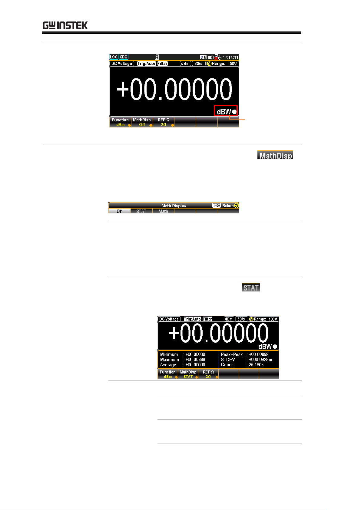
GDM-906X Series User Manual
Watt result
appears
Shows measured
dBW (Watt) value
F2 (MathDisp) key
to show STAT &
Math
Press the F2 (MathDisp) key to show the
Math Display menu as the figure below
shown. Proceed to the F2 (STAT) or F3
(Math) display in accord with the
following chapters.
Show STAT result
Background
The STAT page in MathDisp allows you to
make statistical calculations for several
measurements including Minimum,
Maximum, Average Peak-Peak, Standard
Deviation and Count.
Operation
Press the F2 (STAT) key to show
the statistical data immediately as the figure
below.
View Data
+00.00000 dBW
Indicates the latest dBW value
Minimum
Indicates the minimum data
value
Maximum
Indicates the maximum data
value
96

ADVANCED MEASUREMENT
Average
Indicates the mean (average)
value
Peak-Peak
Indicates the peak to peak data
STDEV
Indicates the standard deviation
of the data
Count
Indicates the latest counts of
dBm
Show Math result
Background
The Math page in MathDisp allows you to
view mathematical calculations for several
parameters.
Operation
Press the F3 (Math) key to show
the mathematical analysis instantly as
below.
View Data
+00.00000 dBW
Indicates the latest dBW value
Measure:
+000.0006V
Indicates the originally
measured Voltage value
RefΩ
Indicates the defined reference
Ω value.
Deactivate
dBm/dBW
measurement
To cancel the dBm/dBW measurement, press
the F1 (Function) key followed by clicking F1
(OFF) key to deactivate or simply activate
another measurement.
Applicable to
Equation
dB
dBm – dBmref
dBm
10 x log10 (1000 x Vreading2 / Rref)
Measure dB
97

GDM-906X Series User Manual
Parameters
dBmref
Reference dBm value
Background
dB is, specifically, defined as [dBm−dBmref]. When the
dB measurement is activated, the GDM-9060/9061
calculates the dBm using the reading at the first moment
and stores it as dBmref.
Activate dB
Press the Shift + Math key to
activate Math setting menu as the
following figure shown.
Further press the F1 (Function) key
to enter the Math Function menu as
the figure shown below.
Press F2 (dB) key to enable the dB
function. The screen, after activation,
will appear as figure below.
dB result appears
Measured
dB Value
Indicator dB On
F3 (REF Ω) to
select reference
resistance
To change the reference resistance,
press the F3 (REF Ω) key to enter the
setting menu. Scroll the Knob key or
press Number keys to enter the
desired value of reference resistance.
Push the F6 (Enter) key or the
Knob key (Enter) to confirm the
input reference resistance.
or
98

ADVANCED MEASUREMENT
Resistance List
2 4 8
16
50
75
93
110
124
125
135
150
250
300
500
600
800
900
1000
1200
8000
F4 (Ref Method)
to select dB
reference method
Reference method involves the ways to
calculate dB value. When dBm option is
selected, user can specify a definite dBm value
for dB calculation. If selecting Voltage
option, system regards the defined voltage
value as the Vreading parameter for dBm
calculation, thus resulting in different dB
value than the previous option.
Press the F4 (RefMethod) key to enter the dB
Ref Method menu followed by clicking the
F1 (Voltage) or F2 (dBm) key to determine
which method of calculation to proceed to.
F5 (Ref Value) to
define reference
value (voltage or
dBm)
In order to define either voltage or dBm
reference value, both of which are
corresponding to the previous F4 (Ref
Method) option, press the F5 (Ref Value) to
enter the dB Ref Value menu, and use the
Left/Right arrow keys to move cursor
followed by scrolling the Knob key or
pressing Number keys to enter the desired
Ref value. Press the F6 (Enter) key or Knob
key to confirm the input value.
Note: when setting voltage Ref value, press
the function keys to promptly define the unit.
99

GDM-906X Series User Manual
F6 (Ref Value) key
to set the dBm
reference
Press the F6 (Ref Value_Current) key to
instantly make the current dBm value, which is
calculated by the current input voltage with
the equation, as the Ref dBm (dBm reference).
F2 (MathDisp) key
to show STAT &
Math
Press the F2 (MathDisp) key to show the
option menu as the figure below shown.
Proceed to the F2 (STAT) or F3 (Math)
display in accord with the following
chapters.
100
 Loading...