


Dual Measurement Multimeter
GDM-9060/9061
USER MANUAL
GW INSTEK PART NO. 82DM-90610E01
ISO-9001 CERTIFIED MANUFACTURER

This manual contains proprietary information, which is protected by
copyrights. All rights are reserved. No part of this manual may be
photocopied, reproduced or translated to another language without
prior written consent of Good Will company.
The information in this manual was correct at the time of printing.
However, Good Will continues to improve products and reserves the
right to change specifications, equipment, and maintenance
procedures at any time without notice.
Good Will Instrument Co., Ltd.
No. 7-1, Jhongsing Rd., Tucheng Dist., New Taipei City 236, Taiwan (R.O.C.).

Table of Contents
Table of Contents
SAFETY INSTRUCTIONS .................................................... 5
Safety Symbols .................................................................... 5
Safety Guidelines ................................................................. 6
GETTING STARTED .......................................................... 10
Front Panel Overview .......................................................... 13
Rear Panel Overview ............................................................ 18
Status Bar ............................................................................ 21
Set Up.................................................................................. 24
BASIC MEASUREMENT .................................................... 26
Basic Measurement Overview ............................................. 27
AC/DC Voltage Measurement .............................................. 30
AC/DC Current Measurement ............................................. 37
2W/4W Resistance Measurement ........................................ 41
Continuity Test .................................................................... 44
Diode Measurement ............................................................ 46
Frequency/Period Measurement .......................................... 47
Capacitance Measurement .................................................. 51
Temperature Measurement ................................................. 54
DUAL MEASUREMENT .................................................... 64
Dual Measurement .............................................................. 64
ADVANCED MEASUREMENT ........................................... 70
Advanced Measurement Overview ...................................... 71
Relative Value Measurement ............................................... 72
Hold Measurement ............................................................. 74
Trigger Setting ..................................................................... 77
Filter Setting ........................................................................ 83
Math Measurement ............................................................. 86
DIGITAL I/O ................................................................... 110
Digital I/O Overview ........................................................... 111
3

GDM-906X Series User Manual
Application: Compare Mode ............................................... 113
Application: 4094 / User Mode ........................................... 120
Application: External Trigger ............................................... 128
SYSTEM & FIRMWARE ................................................... 130
View System Info ................................................................ 131
Firmware Update ................................................................ 132
MENU SETTING ............................................................. 134
Configure System ............................................................... 135
Configure Display ............................................................... 153
SCREENSHOT & LOG .................................................... 171
Capture ............................................................................... 172
Save Reading ...................................................................... 175
DISPLAY SETTING .......................................................... 179
Digit .................................................................................... 180
Display ................................................................................ 181
REMOTE CONTROL ....................................................... 200
Configure Interface ............................................................. 201
Web Control Interface ......................................................... 233
Command Syntax ................................................................ 238
Command Set ..................................................................... 241
Status system ..................................................................... 327
APPENDIX ...................................................................... 331
Fuse Replacement ............................................................... 332
Battery Replacement ........................................................... 336
Factory Default Parameters ................................................ 338
Specifications ..................................................................... 342
GDM-9061 Section ............................................................. 343
GDM-9060 Section ............................................................. 354
Declaration of Conformity .................................................. 366
INDEX ............................................................................ 367
4
SAFETY INSTRUCTIONS
WARNING
Warning: Identifies conditions or practices that could
result in injury or loss of life.
CAUTION
Caution: Identifies conditions or practices that could
result in damage to the GDM-9060/9061 or to other
property.
DANGER High Voltage
Attention Refer to the Manual
Protective Conductor Terminal
Earth (ground) Terminal
Do not dispose electronic equipment as unsorted
municipal waste. Please use a separate collection facility
or contact the supplier from which this instrument was
purchased.
SAFETY INSTRUCTIONS
This chapter contains important safety instructions that
you must follow when operating the GDM-9060/9061
and when keeping it in storage. Read the following
before any operation to insure your safety and to keep
the GDM-9060/9061 in the best possible condition.
Safety Symbols
These safety symbols may appear in this manual or on the GDM-9060/9061.
5
GDM-906X Series User Manual
General Guideline
CAUTION
Make sure that the voltage input level does not exceed
DC1000V/AC750V.
Make sure the current input level does not exceed 10A.
Do not place any heavy object on the instrument.
Avoid severe impact or rough handling that can lead to
damaging the instrument.
Do not discharge static electricity to the instrument.
Use only mating connectors, not bare wires, for the
terminals.
Do not block or obstruct the cooling fan vent opening.
Do not perform measurement at the source of a
low-voltage installation or at building installations
(Note below).
Do not disassemble the instrument unless you are
qualified as service personnel.
Make sure that the Sense LO terminal to Input LO is
limited to 2Vpk, the Sense HI to Sense LO terminals
are limited to 200Vpk and the Input LO to earth is
limited to 500Vpk.
(Note) EN 61010-1:2010 specifies the measurement categories and
their requirements as follows. The GDM-9060/9061 falls under
category II 300V.
Measurement category IV is for measurement performed at the source
of low-voltage installation.
Measurement category III is for measurement performed in the
building installation.
Measurement category II is for measurement performed on the circuits
directly connected to the low voltage installation.
Power Supply
WARNING
AC Input voltage: 100/120/220/240 V AC ±10%,
50Hz / 60Hz / 400Hz ±10%
The power supply voltage should not fluctuate more
than 10%.
Connect the protective grounding conductor of the
AC power cord to an earth ground, to avoid electrical
shock.
Safety Guidelines
6
SAFETY INSTRUCTIONS
WARNING
(GDM-9061 only)
Due to the fact that the Front/Rear Input Switch on
the front panel is not proposed as an active
multiplexer, do Not change the input switch when
signals are present on either rear or front set of
terminals. Intrument damage and risk of electric shock
may occur if switching the input switch when high
voltage or current is present.
Fuse
WARNING
Fuse type: T0.25A 100/120 VAC
T0.125A 220/240 VAC
Make sure the correct type of fuse is installed before
power up.
To avoid risk of fire, replace the fuse only with the
specified type and rating.
Disconnect the power cord before fuse replacement.
Make sure the cause of a fuse blowout is fixed before
fuse replacement.
Cleaning the
Instrument
Disconnect the power cord before cleaning.
Use a soft cloth dampened in a solution of mild
detergent and water. Do not spray any liquid into the
GDM-9060/9061.
Do not use chemicals or cleaners containing harsh
material such as benzene, toluene, xylene, and acetone.
Operation
Environment
Location: Indoor, no direct sunlight, dust free, almost
non-conductive pollution (Note below)
Temperature: Full accuracy for 0°C to 55°C.
Humidity:
< 30°C: < 80%RH (non-condensing)
30°C~40°C: <70%RH (non-condensing)
>40°C: <50%RH (non-condensing)
Altitude: <2000m
7

GDM-906X Series User Manual
(Note) EN 61010-1:2010 specifies the pollution degrees and their
requirements as follows. The GDM-9060/9061 falls under degree 2.
Pollution refers to “addition of foreign matter, solid, liquid, or
gaseous (ionized gases), that may produce a reduction of dielectric
strength or surface resistivity”.
Pollution degree 1: No pollution or only dry, non-conductive pollution
occurs. The pollution has no influence.
Pollution degree 2: Normally only non-conductive pollution occurs.
Occasionally, however, a temporary conductivity caused by
condensation must be expected.
Pollution degree 3: Conductive pollution occurs, or dry, non-conductive
pollution occurs which becomes conductive due to condensation which
is expected. In such conditions, equipment is normally protected
against exposure to direct sunlight, precipitation, and full wind pressure,
but neither temperature nor humidity is controlled.
Storage
Environment
Location: Indoor
Temperature: −40°C to 70°C
Humidity: <90%RH(non-condensing)
Disposal
Do not dispose this instrument as unsorted municipal
waste. Please use a separate collection facility or contact
the supplier from which this instrument was purchased.
Please make sure discarded electrical waste is properly
recycled to reduce environmental impact.
8
SAFETY INSTRUCTIONS
Green/ Yellow:
Earth
Blue:
Neutral
Brown:
Live (Phase)
Power cord for the United Kingdom
When using the GDM-9060/9061 in the United Kingdom, make sure the
power cord meets the following safety instructions.
NOTE: This lead / appliance must only be wired by competent persons
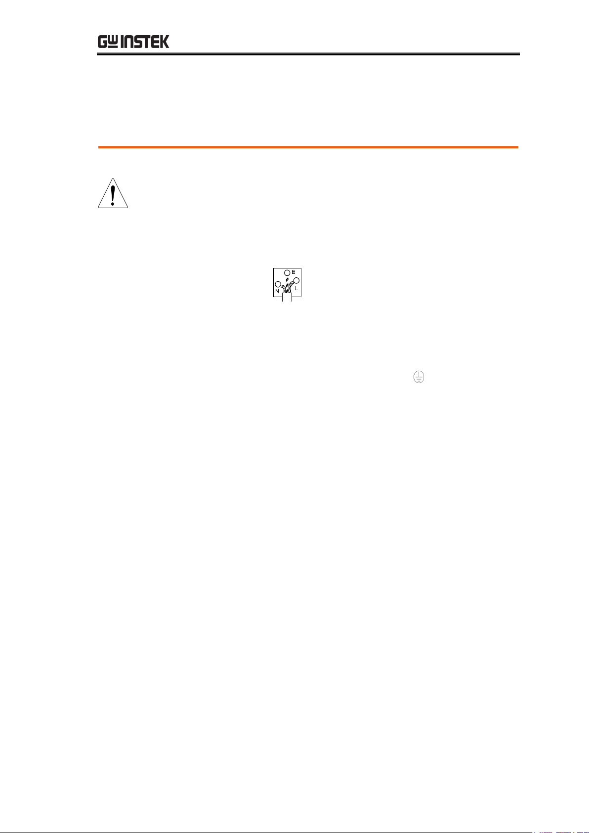
WARNING: THIS APPLIANCE MUST BE EARTHED
IMPORTANT: The wires in this lead are coloured in accordance with the
following code:
As the colours of the wires in main leads may not correspond with the
coloured marking identified in your plug/appliance, proceed as follows:
The wire which is coloured Green & Yellow must be connected to the Earth
terminal marked with either the letter E, the earth symbol or coloured
Green/Green & Yellow.
The wire which is coloured Blue must be connected to the terminal which is
marked with the letter N or coloured Blue or Black.
The wire which is coloured Brown must be connected to the terminal marked
with the letter L or P or coloured Brown or Red.
If in doubt, consult the instructions provided with the equipment or contact
the supplier.
This cable/appliance should be protected by a suitably rated and approved
HBC mains fuse: refer to the rating information on the equipment and/or
user instructions for details. As a guide, a cable of 0.75mm2 should be
protected by a 3A or 5A fuse. Larger conductors would normally require 13A
types, depending on the connection method used.
Any exposed wiring from a cable, plug or connection that is engaged in a live
socket is extremely hazardous. If a cable or plug is deemed hazardous, turn
off the mains power and remove the cable, any fuses and fuse assemblies. All
hazardous wiring must be immediately destroyed and replaced in accordance
to the above standard.
9

GDM-906X Series User Manual
GETTING STARTED
This chapter describes the GDM-9060/9061 in a nutshell,
including an Overview of its main features and front /
rear panel introduction. After going through the
Overview, follow the Power-up sequence to properly
setup the GDM-9060/9061.
Please note the information in this manual was correct at
the time of printing. However as GW Instek continues to
improve its products, changes can occur at any time
without notice. Please see the GW Instek website for the
latest information and content.
Front Panel Overview .......................................................... 13
Measurement Keys (basic) ........................................................ 15
Measurement Keys (advanced) ................................................. 17
Rear Panel Overview ........................................................... 18
Status Bar ........................................................................... 21
Set Up ................................................................................. 24
Horizontal/Tilt/Vertical Applications ........................................ 24
Power Up .................................................................................. 25
10

GETTING STARTED
Performance
The highest DCV accuracy:
GDM-9061: 35ppm
GDM-9060: 75ppm
The highest current:
GDM-9061: 10A
GDM-9060: 3A
The highest voltage: 1000V
The highest ACV frequency response: 300 kHz
The fastest sampling rate:
1k Readings/sec (GDM-9060)
10k Readings/sec (GDM-9061)
Internal memory:
10k read memory (GDM-9060)
100k read memory (GDM-9061)
Data Logging to USB
Features
6
2
1
digits
Multi functions: ACV, DCV, ACI, DCI, 2W/4W R, Hz,
Temp, Continuity, Diode, Period, Capacitance test,
REL, dBm, Hold, MX+B, 1/X, REF%, dB, Compare
and Statistics.
Manual or Auto ranging
AC true RMS
Built-in DC Ratio function
Up to 3 temerature measurements: RTD, Thermistor
and Thermocouples (Cold-Junction Compensation)
Graph Display: BarMeter, TrendChart, Histogram
Interface
USB device/RS232/GPIB(optional)/LAN for remote
control
9-pin Digital I/O port
USB device port supports USBCDC and USBTMC
USB Host
GDM-9060/9061 Characteristics
The GDM-9060/9061 is a portable, dual-display digital
multimeter suitable for a wide range of applications, such
as production testing, research, and field verification.
11

GDM-906X Series User Manual
Optional Items
GPIB card
GTL-207A
GTL-234
GTL-246
GTL-205
GTL-308
Test leads
RS-232 Cable , 2000mm
USB Cable, USB 2.0, A-B type, 1200mm
Temperature Probe Adapter with
Thermal Coupling (K-type)
4W+Shield Test leads , 1.5M
12
GETTING STARTED
1
2
3
4
5 8 7 0 A B
6 9 C D
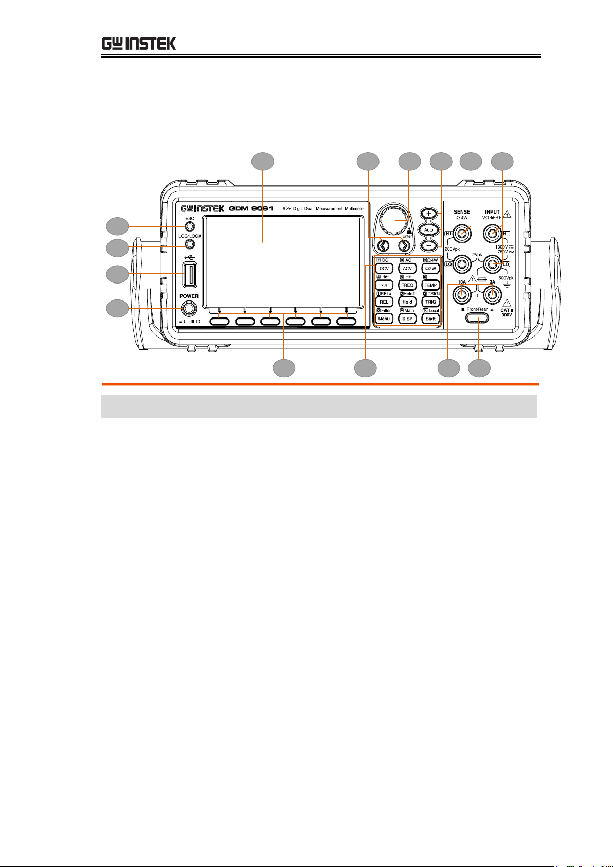
Item
Description
1
ESC (Escape) Key
2
Print screen / Data log Key
3
USB Host Port
4
Power Switch
5
Main Display
6
Function keys (F1 through F6, functions vary per modes)
7
Knob key
8
Arrow Keys
9
Measurement Keys
0
Range Selection Keys
A
HI and LO Sense Terminals
B
HI and LO Input Terminals
C
AC/DC Current Input Terminals (10 A terminal available on
GDM-9061 only)
D
Front/Rear Input Switch (GDM-9061 only)
Front Panel Overview
13
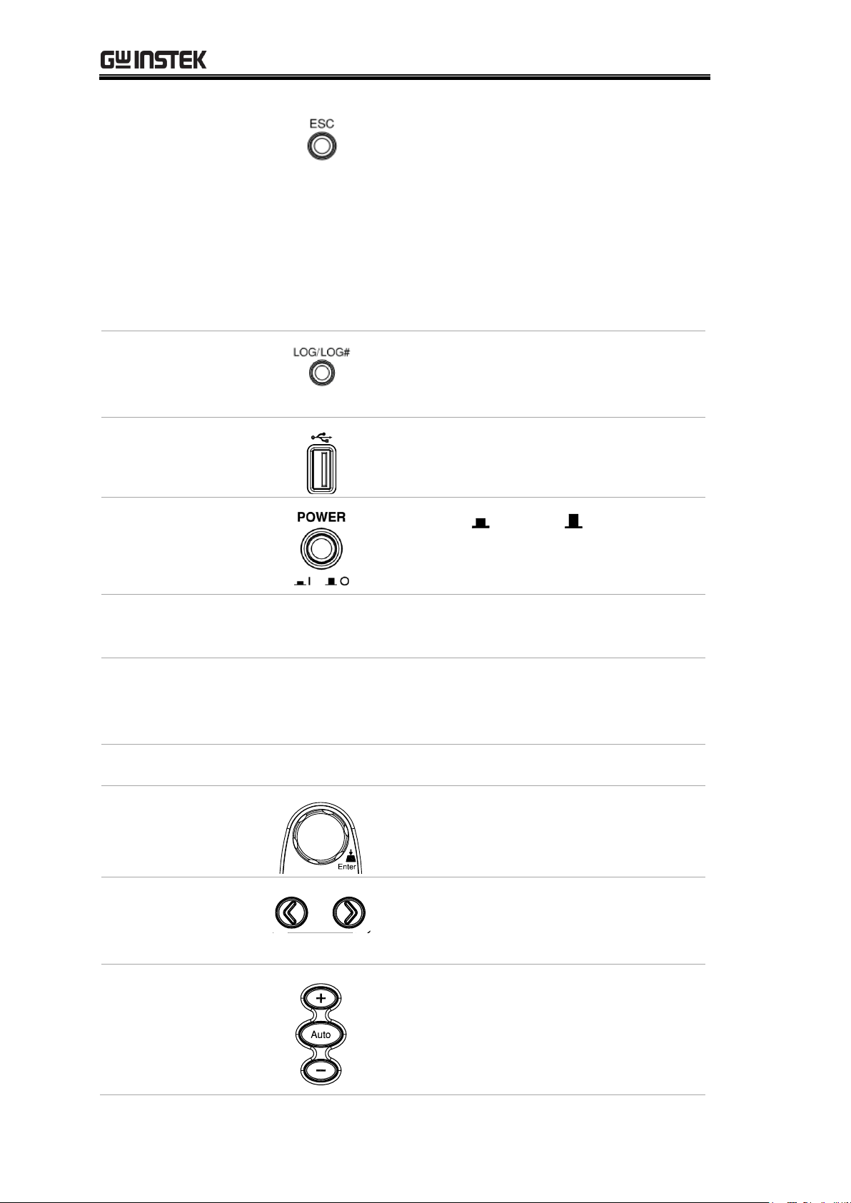
GDM-906X Series User Manual
ESC (Escape) Key
Single press to escape from current page.
Presses and holds the ESC key for 2
seconds to toggle between full display
and simple display, which conceals the
status bar, math display as well as
additional info for lightweight use.
Refer to page 21, page 160 and page 168
for more details of status bar, math
display and additional info, respectively.
Screenshot / Data
Log Saving Key
Captures the current screenshot or saves
the data log for reading. For details, refer
to page 171.
USB Host Port
Connects with USB flash drive for data
storage.
Power Switch
Turns On or Off the main
power. For the power up sequence, see
page 25.
Main Display
The 4.3”TFT LCD shows measurement results and
parameters. For display configurations, see page 153.
Measurement
Keys
There are 4 rows in total of both basic and advanced
measurement keys deployed on the front panel. For the
details, refer to page 15 and page 17.
Function Keys
The 6 keys have varied functions per different settings.
Knob Key
Scrolls the knob to select parameters in
various setting pages. Press the key until
click to confirm setting.
Arrow Keys
Presses the left or right arrow keys to
move parameter cursor rightward or
leftward per requirement.
Range Selection
Keys
Presses the Auto key to activate
auto-range mode, whilst clicking “+” or
“–“ key can increase or decrease range
parameter, respectively.
14
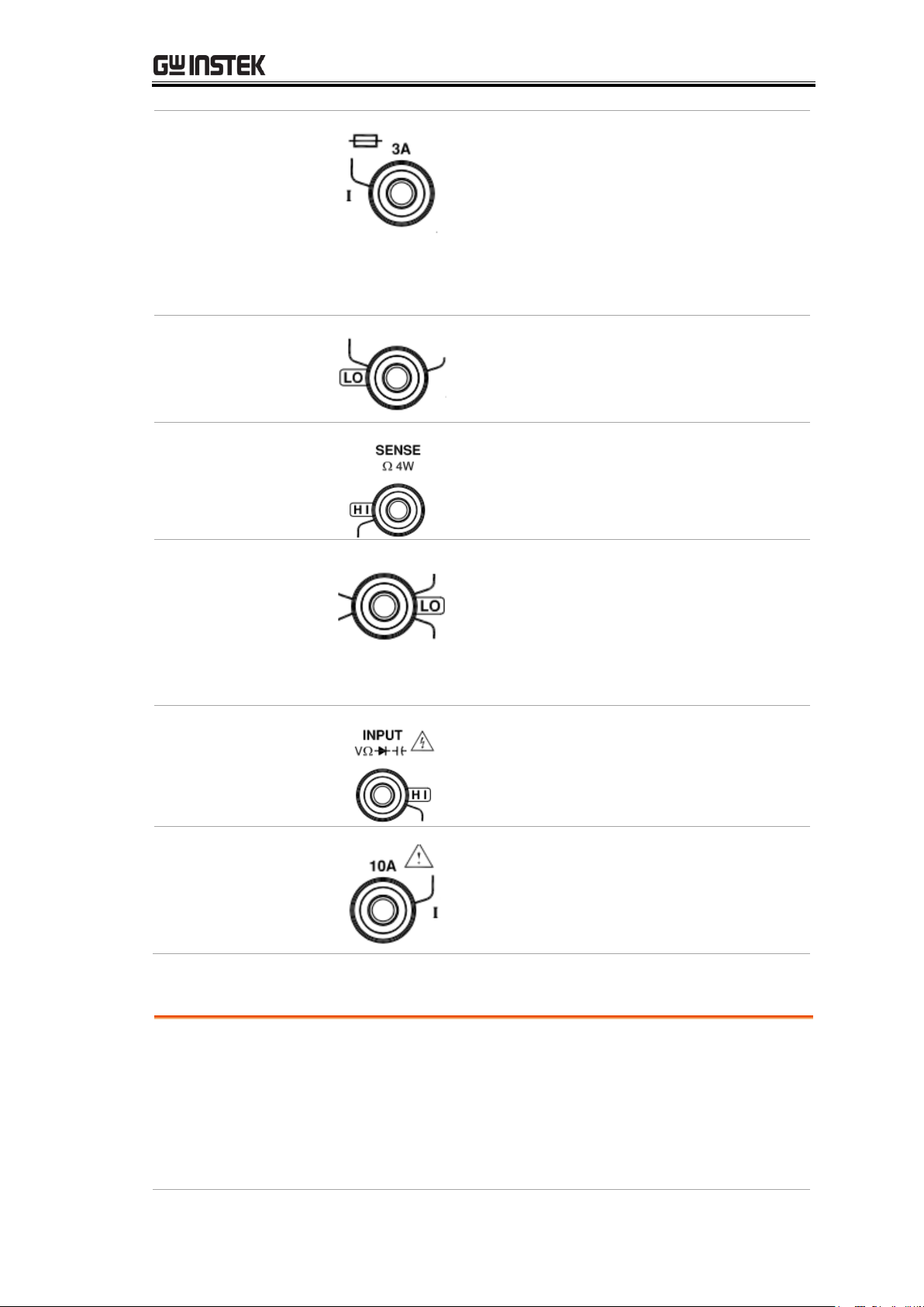
GETTING STARTED
DC/AC 3A
Terminal
DC/AC current input
DC: 100μA~3A
AC: 100μA~3A
For details see page 37.
For the fuse replacement procedure, see
page 333.
Sense LO
Terminal
Accepts LO sense line in 4W resistance
measurement. For details, see page 41.
Sense HI
Terminal
Accepts HI sense line in 4W resistance
measurement. For details, see page 41.
Input LO
Terminal
Accepts ground (COM) line in all
measurements except the sense line in
4W Resistance (page 41).
The maximum withstand voltage
between this terminal and earth is
500Vpk.
Input HI
Terminal
Used as an input port for all
measurements except for DC/AC
Current measurements.
DC/AC 10A
Terminal
(GDM-9061 only)
Accepts DC/AC Current input.
For DCI or ACI details, see page 37.
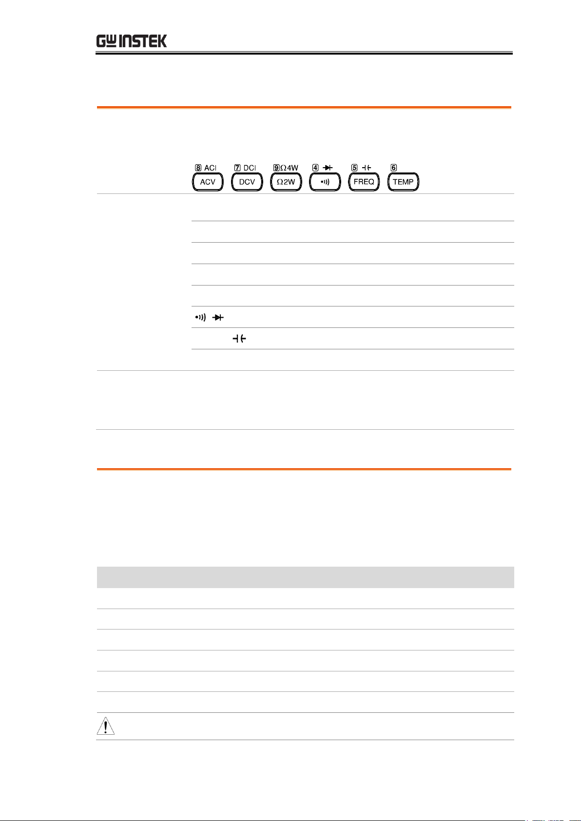
Background
The upper 2 rows of measurement keys are used for
basic GDM-9060/9061 measurements such as voltage,
current, resistance, continuity, diode, frequency, period,
capacitance and temperature. Each key has a primary
and secondary function individually. The secondary
function is accessed in conjunction with the Shift key.
Measurement Keys (basic)
15
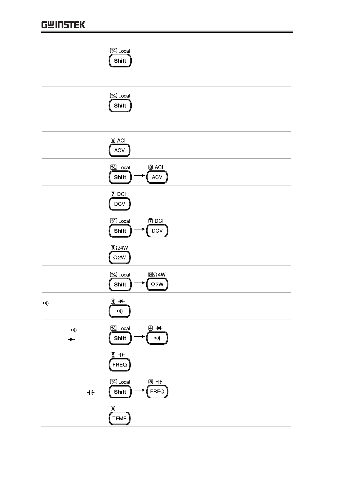
GDM-906X Series User Manual
Shift
The Shift key is used to select the
secondary functions assigned to each
front panel key. When pressed, the
Shift indicator appears in the display.
Local
For the Local key, it helps release
from the remote control and
returns the instrument to local
panel operation (page 201).
ACV
Measures AC Voltage (page 30).
Shift → ACV (ACI)
Measures AC Current (page 37).
DCV
Measures DC Voltage (page 30).
Shift → DCV (DCI)
Measures DC Current (page 37).
Ω2W (Resistance)
Measures 2-wire Resistance (page
41).
Shift → Ω2W (Ω4W
Resistance)
Measures 4-wire Resistance (page
41 ).
(Continuity)
Tests Continuity (page 44).
Shift →
(Diode )
Tests Diode (page 46).
FREQ (Frequency)
Measures Frequency (page 47).
Shift + FREQ
(Capacitance )
Measures Capacitance (page 51).
TEMP
(Temperature)
Measures Temperature (page 54).
16
GETTING STARTED
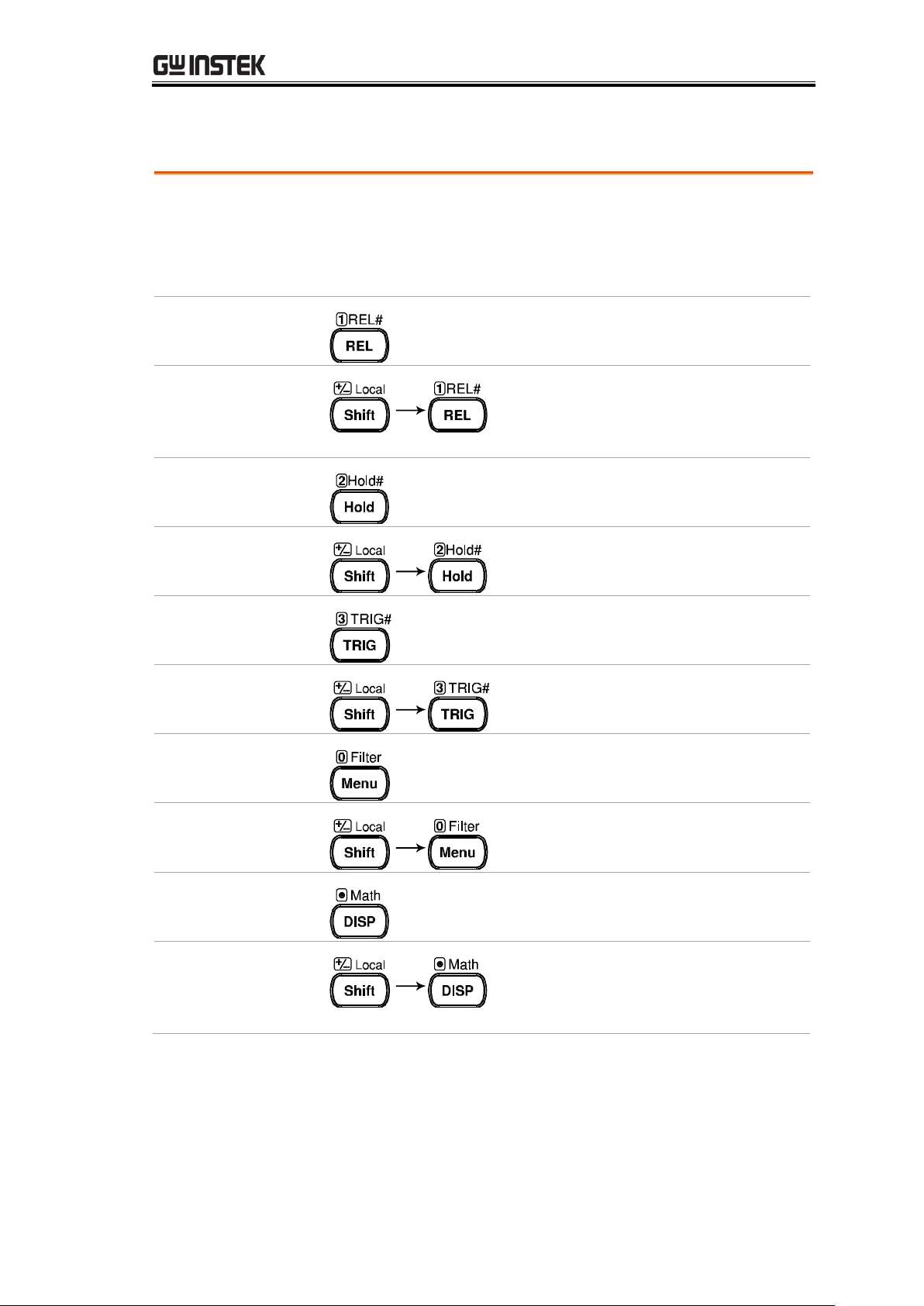
Background
The lower 2 rows of measurement keys are used for
more advanced functions. Each key has a primary and
secondary function. The secondary function is accessed
in conjunction with the Shift key.
REL
Measures the Relative value (page
72).
Shift → REL
(REL#)
Manually sets the reference value for
the Relative value measurement
(page 72).
Hold
Activates the Hold function (page
74).
Shift → Hold
(Hold#)
Manually sets the parameters for the
Hold measurement (page 74).
TRIG (Trigger)
Activates the Trigger function (page
77).
Shift → TRIG
(TRIG#)
Manually sets the parameters for the
Trigger function (page 77).
Menu
Enters the setting pages in various
Menus (page 134).
Shift → Menu
(Filter)
Manually sets the parameters for the
Filter function (page 83).
DISP
Display settings (page 179).
Shift → DISP
(Math)
The Math functions including dB,
dBm, Compare, MX+B, 1/X and
Percent manually (page 86).
Measurement Keys (advanced)
17
GDM-906X Series User Manual
1
240
2 5 9 0 A
4 3 6 7 8 B
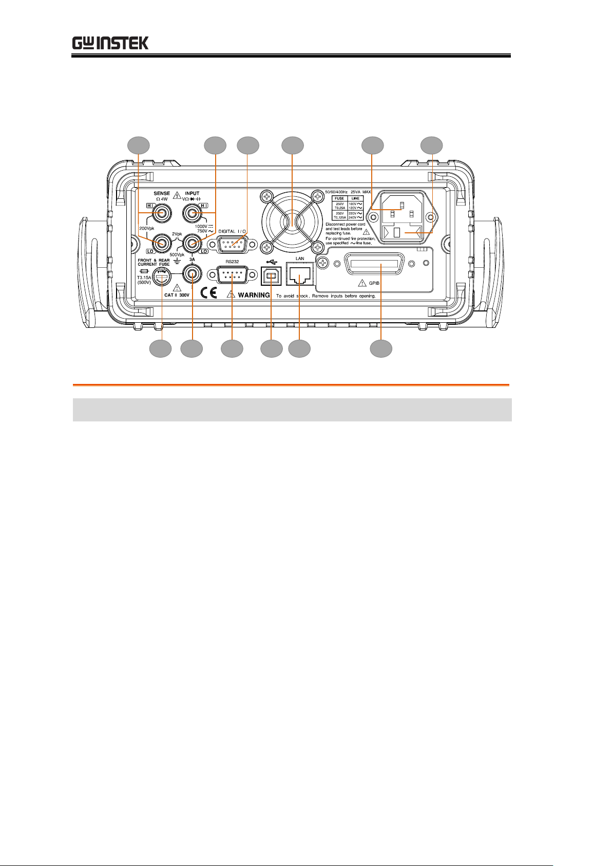
Item
Description
1
HI and LO Sense Terminals (GDM-9061 only)
2
HI and LO Input Terminals (GDM-9061 only)
3
3 A Current Terminal (GDM-9061 only)
4
3 A Current Terminal Fuse
5
DIGITAL I/O Connector
6
RS-232 Interface Connector
7
USB Interface Connector (B Type)
8
Ethernet (LAN) Connector
9
Fan Vents
0
AC Mains Input (Power Cord Socket)
A
AC Mains Line Voltage Selector and Fuse Socket
B
GPIB Connector (optional)
Rear Panel Overview
18
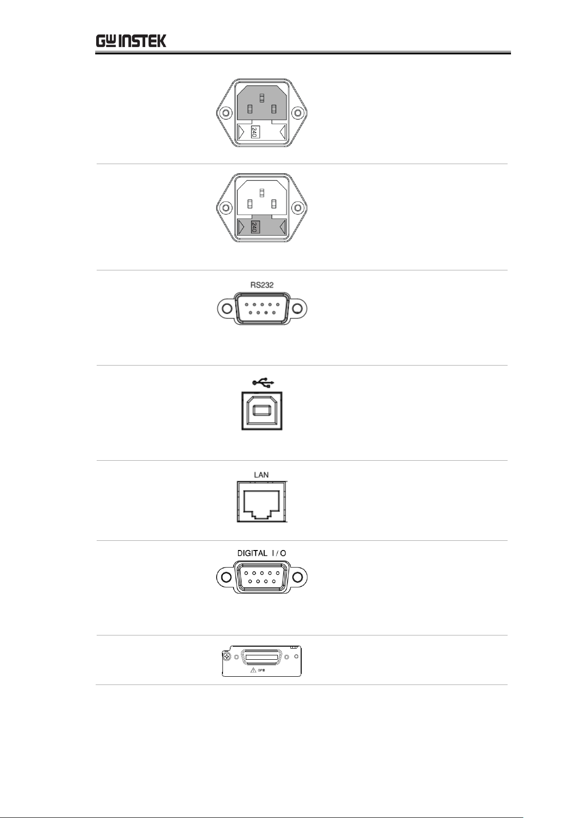
GETTING STARTED
Power Cord Socket
Accepts the power cord. AC
100/120/220/240V ±10%,
50Hz / 60Hz /400Hz ±10%.
For power on sequence, see page
25.
Fuse Socket
Holds the main fuse:
100/120 VAC: T0.25A
220/240 VAC: T0.125A
For fuse replacement details, see
page 332.
RS-232C port
Accepts an RS-232C cable for
remote control; DB-9 male
connector.
For remote control details, see
page 205.
USB device port
Accepts a USB device cable for
remote control; Type B, female
connector.
For remote control details, see
page 202.
LAN port
Accepts a LAN for remote
control;
For remote control details, see
page 216.
Digital I/O port
Accepts a digital I/O cable for the
Hi/Lo limit tests; DB-9 pin,
female connector.
For digital I/O details, see page
110.
Optional GPIB port
Accepts an optional GPIB card.
For GPIB details, see page 213.
19
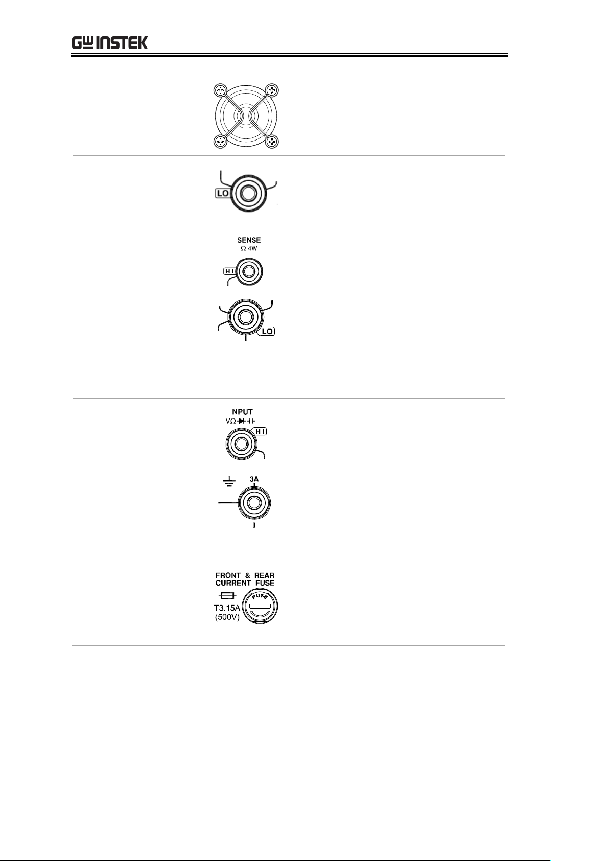
GDM-906X Series User Manual
Fan Vents
For heat ventilation when machine
is under operation.
Sense LO Terminal
(GDM-9061 only)
Accepts LO sense line in 4W
resistance measurement. For
details, see page 41.
Sense HI Terminal
(GDM-9061 only)
Accepts HI sense line in 4W
resistance measurement. For
details, see page 41.
Input LO Terminal
(GDM-9061 only)
Accepts ground (COM) line in all
measurements except the sense
line in 4W Resistance (page 41).
The maximum withstand voltage
between this terminal and earth is
500Vpk.
Input HI
Terminal
(GDM-9061 only)
Used as an input port for all
measurements except for DC/AC
Current measurements.
DC/AC 3A Terminal
(GDM-9061 only)
DC/AC current input
DC: 100μA~3A
AC: 100μA~3A
For details see page 37.
DC/AC 3.15A Input
Current Fuse
Holds the current fuse: T3.15A,
500V , 5*20mm
For fuse replacement details, see
page 333.
20
GETTING STARTED
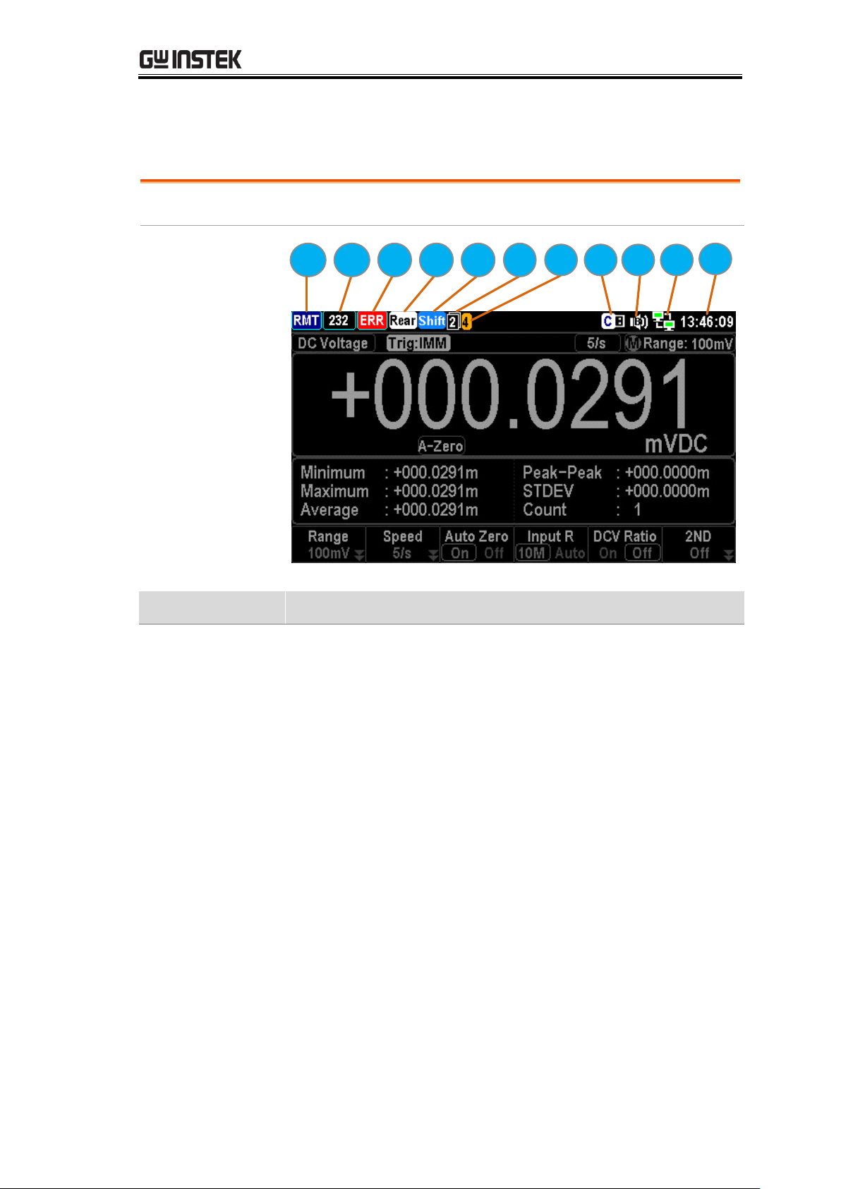
Background
Identify each icon within the top status bar.
Status Bar
Display
1 2 3 4 5 6 7 8 9 0
A
Item
Description
1
Local/Remote control icon
2
RS-232/USB-CDC/USB-TMC/LAN/GPIB interface icon
3
Error icon for commands from remote control
4
Rear panel switch icon
5
Shift key identification icon
6
The first and second function menu switch icon
7
Digital I/O mode icon (User/4094)
8
USB flash drive connection icon
9
Beep/Key Sound setting icon
0
Internet connection status icon
A
Time display
Status Bar
21
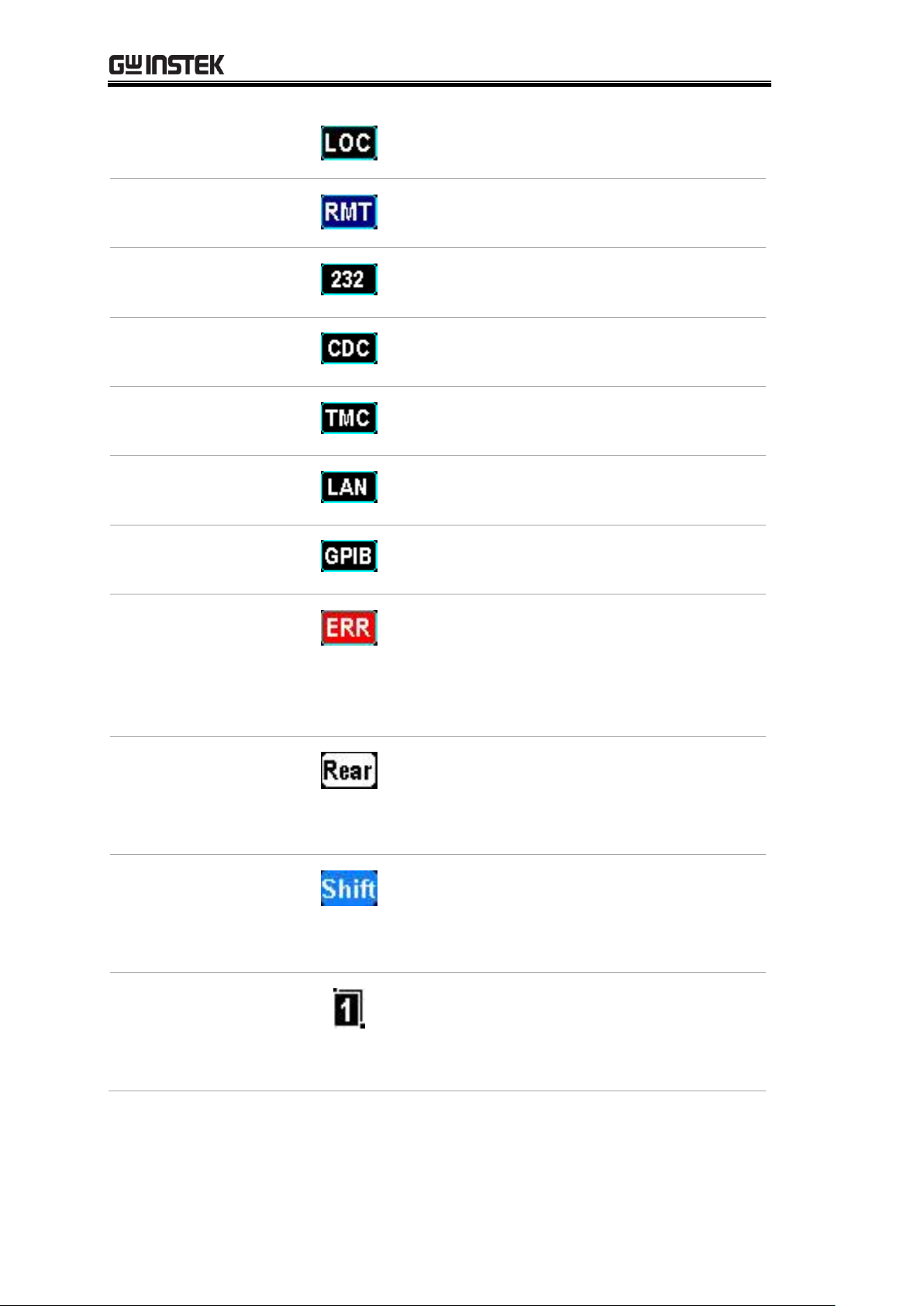
GDM-906X Series User Manual
Local Control
It indicates the unit is under local
control mode.
Remote Control
It indicates the unit is under remote
control. Refer to page 200 for details.
RS-232
It indicates RS-232 interface is activated.
Refer to page 205 for details.
USB - CDC
It indicates USB - CDC interface is
activated. Refer to page 205 for details.
USB - TMC
It indicates USB - TMC interface is
activated. Refer to page 205 for details.
LAN
It indicates LAN interface is activated.
Refer to page 216 for details.
GPIB
It indicates GPIB interface is activated.
Refer to page 213 for details.
ERROR
It indicates error occurs in commands.
To erase the error icon, it is required to
read or sweep the error by remote
control commands or reboot action.
Refer to page 313 for details.
Rear Panel
It indicates rear panel control. When the
icon appears, only rear panel is available;
otherwise, use front panel for
measurement. Refer to page 18 for details.
Shift
It indicates the shift key is being pressed
ready for in conjunction with other keys
for additional functions. Refer to page
15 for details.
First function
menu
It indicates the active bottom menu
corresponding to function keys is the
first menu. Click the Knob key (Enter)
to switch to the second function menu.
22
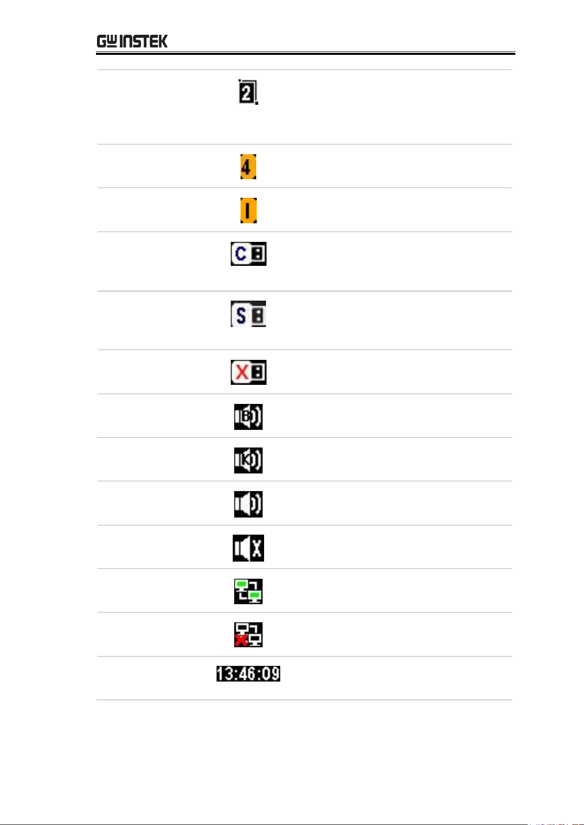
GETTING STARTED
Second function
menu
It indicates the active bottom menu
corresponding to functional keys is the
second menu. Click the Knob key (Enter)
to switch to the first function menu.
Digital I/O –
4094 mode
It indicates Digital I/O – 4094 mode is
enabled. Refer to page 120 for details.
Digital I/O –
User mode
It indicates Digital I/O – User mode is
enabled. Refer to page 120 for details.
Flash Drive –
Capture
It indicates the Capture mode is ready
for the connected flash drive. Refer to
the page 171 for details of Capture.
Flash Drive –
Save Reading
It indicates the Save Reading mode is
ready for the connected flash drive. Refer
to page 175 for details of Save Reading.
Flash Drive –
Failure
It indicates something error occurs and
thus flash drive fails to connect to unit.
Sound – Beep
It indicates sound of beep is enabled.
Refer to page 135 for details.
Sound - Key
It indicates sound of key is enabled.
Refer to page 136 for details.
Sound – All
It indicates sounds of beep and key are
both enabled.
Sound – Off
It indicates sounds of beep and key are
both disabled.
Internet On
It indicates internet connection is
established. Refer to page 216 for details.
Internet Off
It indicates internet connection is Not
well established.
Time Display
It indicates the time display. For detailed
setting, refer to page 138.
23
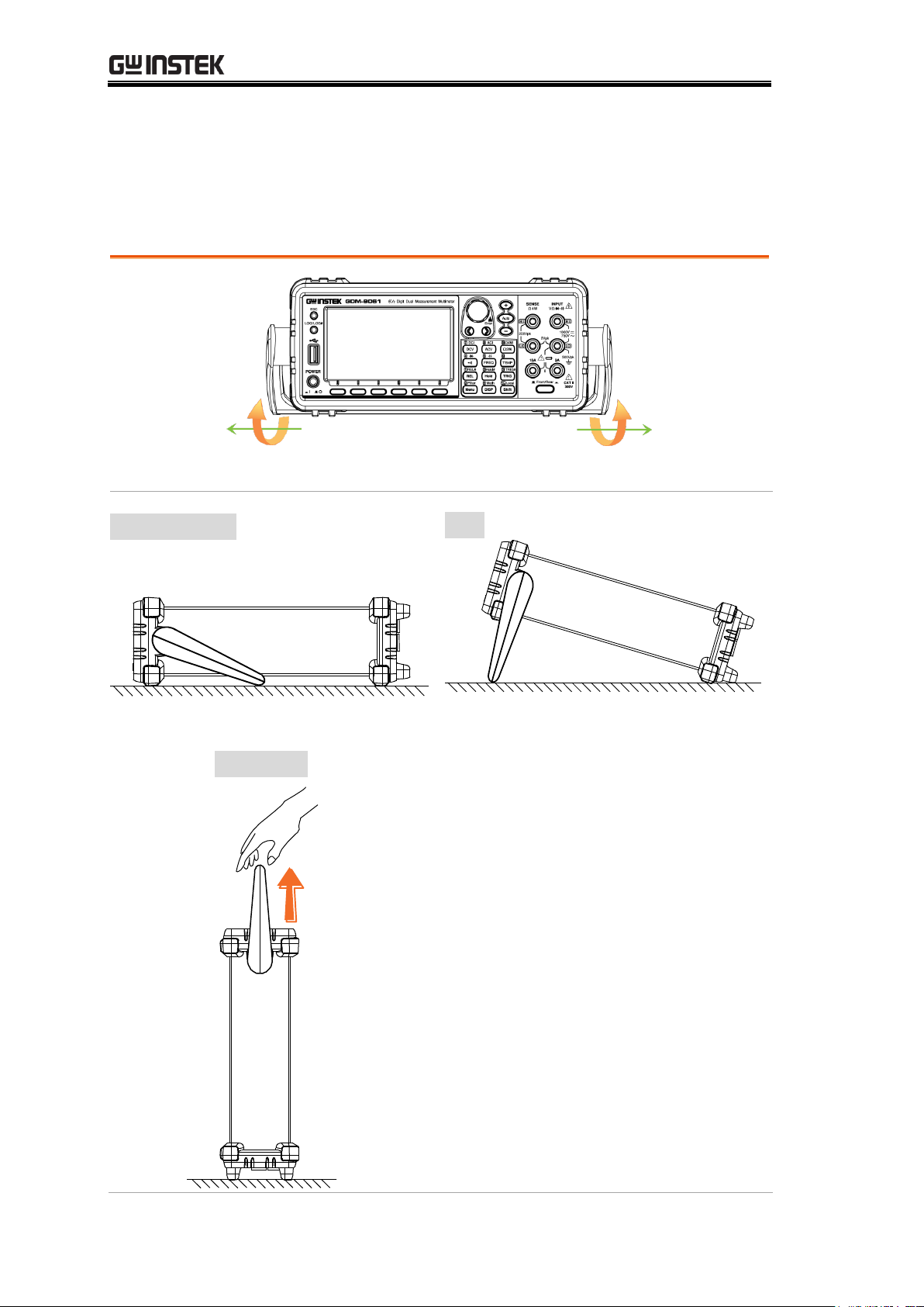
GDM-906X Series User Manual
Pull out the handle sideways and rotate it clockwise for the applications below.
Horizontal
Tilt
Place the unit horizontally.
Rotate the handle for tilt stand.
Vertical
Place the handle vertically for hand carry.
Set Up
Horizontal/Tilt/Vertical Applications
24
Power Up
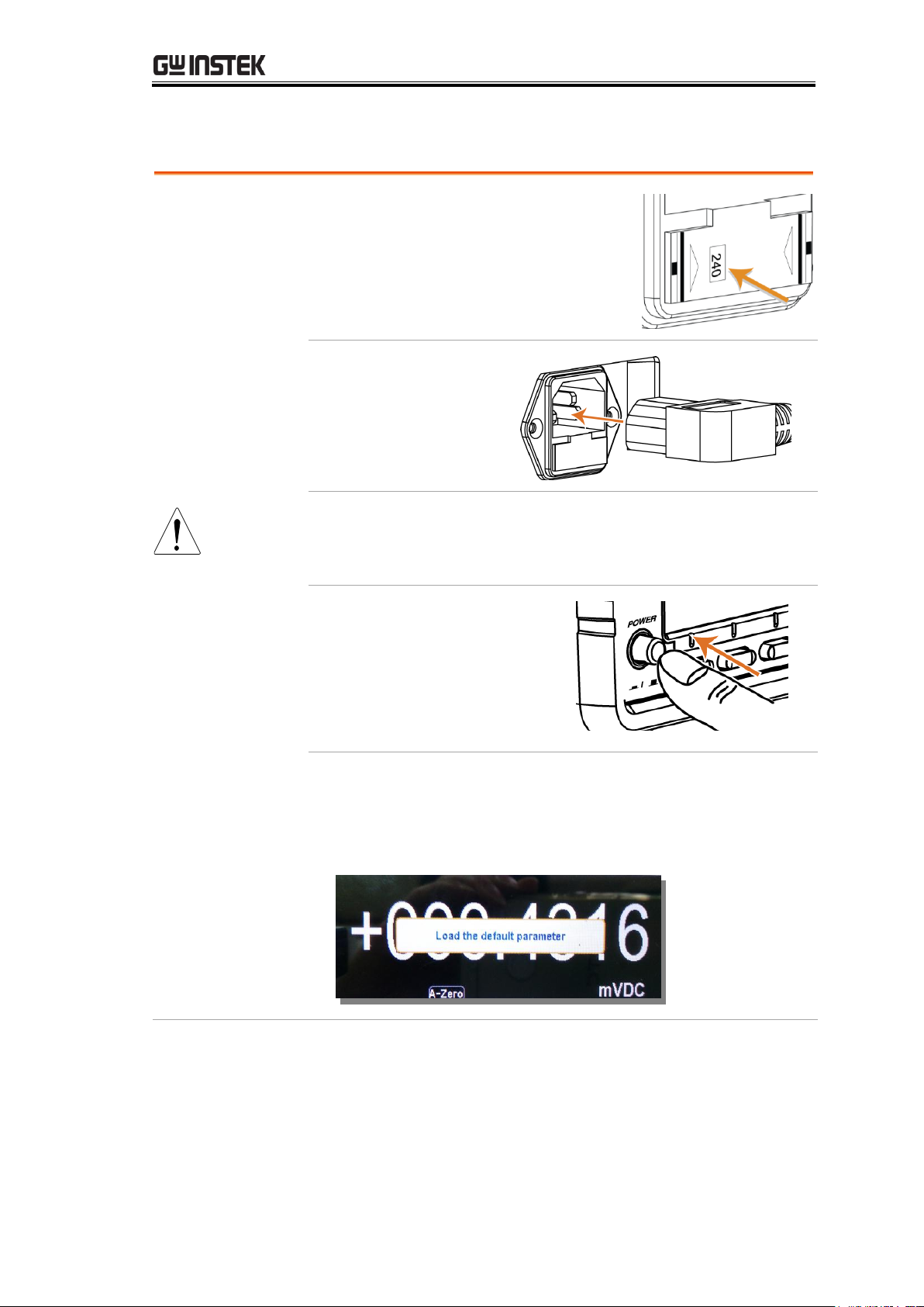
Steps
1. Ensure the correct line voltage is
clearly shown on the fuse socket
(240V in the right figure for
example). If not, see page 332 to
set the proper line voltage and fuse.
2. Connect the power
cord to the AC
Voltage input.
Note
Make sure the ground connector on the power cord is
connected to a safety ground. This will affect the
measurement accuracy.
3. Push the power button
until click to turn on the
main power switch on
the front panel.
4. The screen firstly shows the logo brand of
GWINSTEK followed by the message “Load the
default parameter” indicating default parameter is loaded
in the initial startup.
GETTING STARTED
25

GDM-906X Series User Manual
BASIC MEASUREMENT
Basic Measurement Overview ............................................ 27
Refresh Rate .............................................................................. 27
Automatic (Internal)/Single Triggering ..................................... 29
AC/DC Voltage Measurement ............................................. 30
Select Voltage Range ................................................................. 31
General Voltage Setting ............................................................. 32
Voltage Conversion Table .......................................................... 35
Crest Factor Table ...................................................................... 36
AC/DC Current Measurement ............................................ 37
Select Current Range ................................................................. 39
General Current Setting ............................................................ 40
2W/4W Resistance Measurement ....................................... 41
Select Resistance Range ............................................................ 42
General Resistance Setting ....................................................... 43
Continuity Test .................................................................... 44
Set Continuity Threshold ........................................................... 45
Diode Measurement ........................................................... 46
Frequency/Period Measurement ......................................... 47
Frequency/Period In-Depth Setting ........................................... 49
Capacitance Measurement ................................................. 51
Cable Open Function ................................................................. 52
Select Capacitance Range .......................................................... 53
Temperature Measurement ................................................. 54
General Temperature Setting .................................................... 55
Thermocouple Sensor Type ....................................................... 56
Reference Junction Temperature (SIM Temperature) ................ 56
Thermocouple Setting ............................................................... 57
RTD 2W/4W Setting .................................................................. 58
Set User Type of RTD 2W/4W .................................................... 59
Thermistor 2W/4W Setting ....................................................... 61
Set User Type of Thermistor 2W/4W ......................................... 62
Dual Measurement ............................................................. 64
Refresh Rate .............................................................................. 67
Connect the Test Leads ............................................................. 68
26
BASIC MEASUREMENT
Background
Basic measurement refers to the several types of measurements
assigned to the upper 2 row keys on the front panel.
Measurement
type
ACV
AC Voltage
DCV
DC Voltage
ACI
AC Current
DCI
DC Current
Ω 2W/ Ω 4W
2-wire and 4-wire Resistance
Continuity/Diode
FREQ
Frequency/Capacitance
TEMP
Temperature
Advanced
measurement
Advanced measurement (page 70) mainly refers to the
operation using the result obtained from one or more of the
basic measurements.
Background
Refresh rate defines how frequently the GDM-9060/9061
captures and updates measurement data. A faster refresh rate
yields a lower accuracy and resolution. A slower refresh rate
yields a higher accuracy and resolution. Consider these
tradeoffs when selecting the refresh rate.
Measurement Type
Refresh Rate Available
DCV/DCI/ 2W/4W
5/s
20/s
60/s
100/s
400/s
1k/s*1
1.2k/s*2
2.4k/s*2
4.8k/s*2
7.2k/s*2
10k/s*2
ACV/ACI
1/s
5/s
20/s
Continuity / Diode
60/s
100/s
400/s
Frequency & Period
1s
100ms
10ms
Capacitance
2/s
Temperature
5/s
20/s
60/s
Note
*1
is applicable to GDM-9060, whilst *2 is specifically for GDM-9061.
Basic Measurement Overview
Refresh Rate
27
GDM-906X Series User Manual
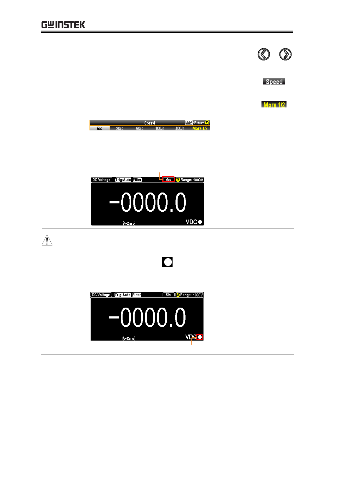
Selection
Procedure
Press the left or right arrow keys to change the
refresh rate.
You can also press the F2 (Speed) key to select a
desired rate for measurement. Press corresponding
function key in accord with the desired option on
screen display. Also, the F6 (More ½) key shows
when available options are more than single page.
The refresh rate will be shown at the upper right
corner of the display. See the example below.
Active Refresh Rate
Note
The refresh rate cannot be set for capacitance measurement.
Reading
indicator
The reading indicator , which is located in the lower-right
corner of display, flashes according to the defined refresh rate
setting.
Reading Indicator
28
BASIC MEASUREMENT
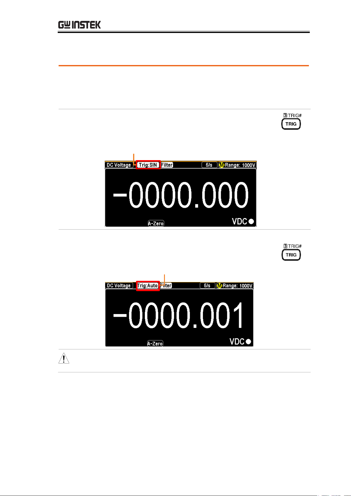
Overview
By default, the GDM-9060/9061 automatically triggers
according to the refresh rate. See the previous page for refresh
rate setting details. The TRIG key, on the other hand, is used to
manually trigger once per click.
Single Trigger
Simply press the TRIG key to Single trigger
measurement. Pressing once stands for trigger for
single time. See the figure below for example.
Indicator Single Trigger Mode
Automatic
(Internal)
Trigger
Press and hold the TRIG key for 2 seconds to
return to the Automatic (Internal) Trigger.
Indicator Auto (Internal)
Trigger Mode
(Press & hold
for 2 seconds)
Note
Single triggering is not supported for capacitance
measurements.
Automatic (Internal)/Single Triggering
29
GDM-906X Series User Manual
Voltage type
AC
0 ~ 750V
DC
0 ~ 1000V
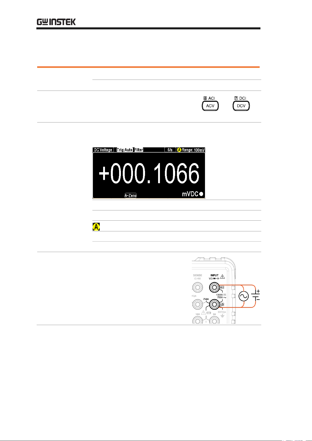
Activate ACV/
DCV
Press the ACV key or DCV key to
measure AC or DC voltage,
respectively.
or
ACV/DCV mode
display appears
The mode will switch to ACV, DCV mode immediately.
See the figure below for example.
DC or AC Voltage
Indicates DC or AC Voltage mode
5/s
Indicates the active refresh rate
Indicates Automatic range selection
Range: 100mV
Indicates the available range of Voltage
+000.1066 mVDC
Indicates the exact measured value
Connect the test
lead and measure
Connect the test lead between the
Input HI and Input LO terminals.
The display updates the reading.
AC/DC Voltage Measurement
30
 Loading...