


Digital Multimeter
GDM-8200 Series
USER MANUAL
GW INSTEK PART NO. 82DM-82550M01
ISO-9001 CERTIFIED MANUFACTURER
This manual contains proprietary information, which is protected by
copyrights. All rights are reserved. No part of this manual may be
photocopied, reproduced or translated to another language without
prior written consent of Good Will company.
The information in this manual was correct at the time of printing.
However, Good Will continues to improve products and reserves
the rights to change specification, equipment, and maintenance
procedures at any time without notice.
Good Will Instrument Co., Ltd.
No. 7-1, Jhongsing Rd., Tucheng City, Taipei County 236, Taiwan.

Table of Contents
3
Table of Contents
SAFETY INSTRUCTIONS ................................................... 5
Safety Symbols ....................................................5
Safety Guidelines ................................................6
GETTING STARTED........................................................... 9
GDM-8200 Series Lineup ..................................10
GDM-8200 Series Characteristics ..................... 11
Front Panel Overview ........................................12
Rear Panel Overview ......................................... 17
Set Up ...............................................................19
BASIC MEASUREMENT ....................................................21
Basic Measurement Overview ...........................22
AC/DC/AC+DC Voltage Measurement .............. 24
AC/DC/AC+DC Current Measurement ..............28
2W/4W Resistance Measurement ..................... 30
Diode Test .........................................................32
Continuity Test ..................................................33
Frequency/Period Measurement .......................36
Temperature Measurement ...............................37
ADVANCED MEASUREMENT...........................................40
Advanced Measurement Overview .................... 41
dBm/dB Measurement......................................43
Max/Min Measurement.....................................45
Relative Value Measurement............................. 46
Hold Measurement ...........................................48
Compare Measurement.....................................49
Math Measurement...........................................52
Dual Display Measurement............................... 56
SYSTEM/DISPLAY CONFIGURATION ..............................57
Refresh Rate Setting..........................................58
Trigger Setting...................................................59
GDM-8200 Series User Manual
4
Digital Filter Setting ..........................................62
Display Light Setting .........................................64
STORE/RECALL ............................................................... 65
Store Measurement Record...............................65
Recall Measurement Record..............................66
Recall Factory Installed Setup ...........................67
SCANNER (OPTIONAL) .................................................. 68
Scanner Installation ..........................................69
Setup Scan ........................................................76
Run Scan ...........................................................82
DIGITAL I/O.................................................................... 85
Digital I/O Terminal Configuration ...................86
REMOTE CONTROL ........................................................ 90
Configure Interface............................................91
Command Syntax ..............................................95
Command Set.................................................... 96
FAQ ................................................................................104
Appendix ........................................................................105
System Information.........................................105
Fuse Replacement ...........................................107
Specification....................................................109
EC Declaration of Conformity..........................115
INDEX ............................................................................116
SAFETY INSTRUCTIONS
5
SAFETY INSTRUCTIONS
This chapter contains important safety instructions that
you must follow when operating GDM-8200 series and
when keeping it in storage. Read the following before any
operation to insure your safety and to keep the best
condition for GDM-8200 series.
Safety Symbols
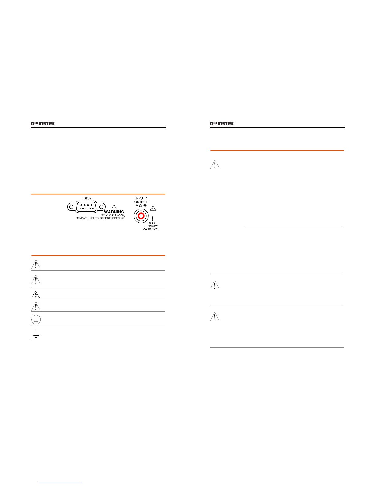
These safety symbols may appear in this manual or on GDM-8200 series.
WARNING
Warning: Identifies conditions or practices that could
result in injury or loss of life.
CAUTION
Caution: Identifies conditions or practices that could
result in damage to GDM-8200 series or to other
properties.
DANGER High Voltage
Attention Refer to the Manual
Protective Conductor Terminal
Earth (ground) Terminal
GDM-8200 Series User Manual
6
Safety Guidelines
• Make sure that the voltage input level does not exceed
DC1000V/AC750V.
• Make sure the current input level does not exceed 10A.
• Do not place any heavy object on GDM-8200 series.
• Avoid severe impacts or rough handling that leads to
damaging GDM-8200 series.
• Do not discharge static electricity to GDM-8200 series.
• Use only mating connectors, not bare wires, for the
terminals.
• Do not block or obstruct the cooling fan vent opening.
• Do not perform measurement at the source of
low-voltage installation or at building installations
(Note below).
• Do not disassemble GDM-8200 series unless you are
qualified as service personnel.
General Guideline
CAUTION
(Note) EN 61010-1:2001 specifies the measurement categories and
their requirements as follows. GDM-8200 series falls under
category I or II.
• Measurement category IV is for measurement performed at the
source of low-voltage installation.
• Measurement category III is for measurement performed in the
building installation.
• Measurement category II is for measurement performed on the
circuits directly connected to the low voltage installation.
• Measurement category I is for measurements performed on circuits
not directly connected to Mains.
Power Supply
WARNING
• AC Input voltage: 100–240 V AC, 50–60Hz
• The power supply voltage should not fluctuate more
than 10%.
• Connect the protective grounding conductor of the
AC power cord to an earth ground, to avoid electrical
shock.
Fus e
WARNING
• Fuse type: T3.15A/ 250V, 20VA
• Make sure the correct type of fuse is installed before
power up.
• To ensure fire protection, replace the fuse only with
the specified type and rating.
• Disconnect the power cord before fuse replacement.
• Make sure the cause of fuse blowout is fixed before
fuse replacement.
SAFETY INSTRUCTIONS
7
Cleaning
GDM-8200 series
• Disconnect the power cord before cleaning.
• Use a soft cloth dampened in a solution of mild
detergent and water. Do not spray any liquid into
GDM-8200 series.
• Do not use chemical or cleaner containing harsh
material such as benzene, toluene, xylene, and acetone.
• Location: Indoor, no direct sunlight, dust free, almost
non-conductive pollution (Note below)
• Relative Humidity: < 75%
• Altitude: < 2000m
• Temperature: 0°C to 40°C (operation), 18°C to 28°C
(full accuracy)
Operation
Environment
(Note) EN 61010-1:2001 specifies the pollution degrees and their
requirements as follows. GDM-8200 series falls under degree 2.
Pollution refers to “addition of foreign matter, solid, liquid, or
gaseous (ionized gases), that may produce a reduction of dielectric
strength or surface resistivity”.
• Pollution degree 1: No pollution or only dry, non-conductive pollution
occurs. The pollution has no influence.
• Pollution degree 2: Normally only non-conductive pollution occurs.
Occasionally, however, a temporary conductivity caused by
condensation must be expected.
• Pollution degree 3: Conductive pollution occurs, or dry,
non-conductive pollution occurs which becomes conductive due to
condensation which is expected. In such conditions, equipment is
normally protected against exposure to direct sunlight, precipitation,
and full wind pressure, but neither temperature nor humidity is
controlled.
Storage
Environment
• Location: Indoor
• Relative Humidity: < 75% (0~35°C), <50% (35~50°C)
• Tem pera tur e: −10°C to 70°C
GDM-8200 Series User Manual
8
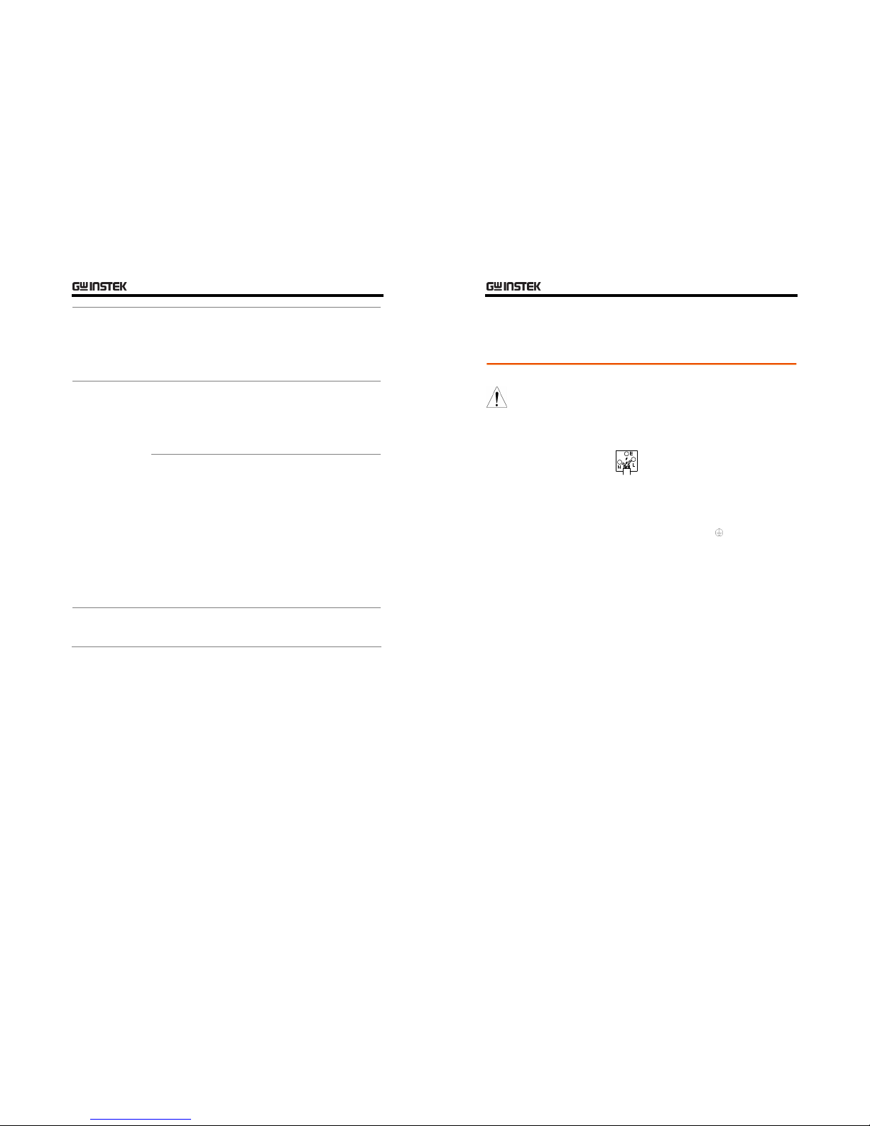
Power cord for the United Kingdom
When using GDM-8200 series in the United Kingdom, make sure the power
cord meets the following safety instructions.
NOTE: This lead / appliance must only be wired by competent persons
WARNING: THIS APPLIANCE MUST BE EARTHED
IMPORTANT: The wires in this lead are coloured in accordance with the
following code:
Green/ Yellow: Earth
Blue: Neutral
Brown: Live (Phase)
As the colours of the wires in main leads may not correspond with the
colours marking identified in your plug/appliance, proceed as follows:
The wire which is coloured Green & Yellow must be connected to the Earth
terminal marked with the letter E or by the earth symbol
or coloured Green
or Green & Yellow.
The wire which is coloured Blue must be connected to the terminal which is
marked with the letter N or coloured Blue or Black.
The wire which is coloured Brown must be connected to the terminal marked
with the letter L or P or coloured Brown or Red.
If in doubt, consult the instructions provided with the equipment or contact
the supplier.
This cable/appliance should be protected by a suitably rated and approved
HBC mains fuse: refer to the rating information on the equipment and/or
user instructions for details. As a guide, cable of 0.75mm2 should be
protected by a 3A or 5A fuse. Larger conductors would normally require 13A
types, depending on the connection method used.
Any moulded mains connector that requires removal /replacement must be
destroyed by removal of any fuse & fuse carrier and disposed of immediately,
as a plug with bared wires is hazardous if a engaged in live socket. Any
re-wiring must be carried out in accordance with the information detailed on
this label.
GETTING STARTED
9
GETTING STARTED
This chapter describes GDM-8200 series in a nutshell,
including its main features, package contents, and front /
rear / display panel introduction. After going through
the overview, follow the Power-up sequence and
Functionality check section to properly setup GDM-8200
series.
Characteristics GDM-8200 Series Lineup .......................................10
GDM-8200 Series Characteristics...........................11
Panel Overview Front Panel Overview .............................................12
Measurement keys (Upper row) .............................13
Measurement keys (Lower row) .............................15
Rear Panel Overview...............................................17
Setup Tilt Stand................................................................19
Power Up................................................................20
GDM-8200 Series User Manual
10
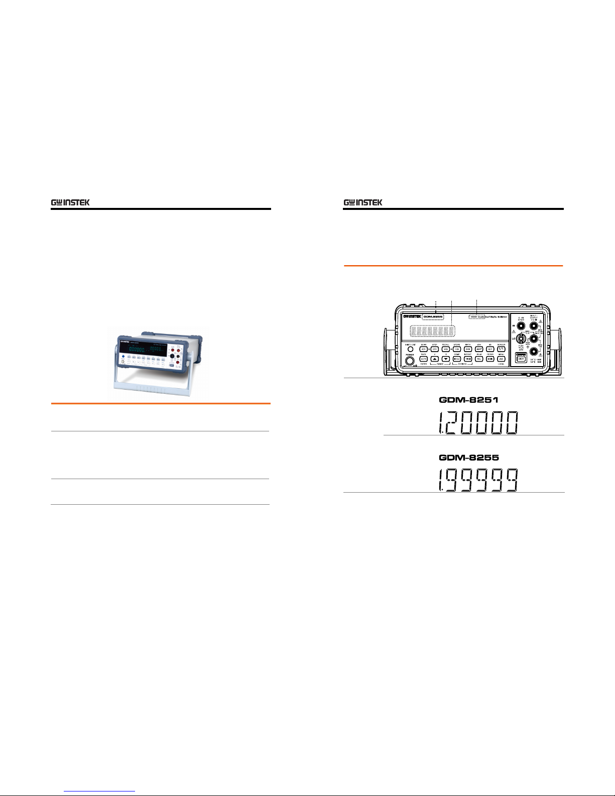
GDM-8200 Series Lineup
GDM-8200 series consists of two models: GDM-8251
and GDM-8255.
Appearance
Both two models are identical except for the model name and
the meter count of the 1
st
display.
Model Name
1st Display
Models GDM-8251
1st display meter: 120,000 counts
GDM-8255
1st display meter: 199,999 counts
GETTING STARTED
11
GDM-8200 Series Characteristics
GDM-8200 series are portable, dual-display digital
multimeters suitable for wide range of applications, such
as production testing, research, and field verification.
Performance
• High DCV accuracy: 0.012%
• High current range: 10A
• High Voltage range: 1000V
• High ACV frequency response: 100kHz
Feat ures
• 120000 meter count (GDM-8251)
• 199999 meter count (GDM-8255)
• Multi functions: ACV, DCV, ACA, DCA, 2W/4W R,
Hz, Continuity, Diode test, MAX/MIN, REL, dBm,
HOLD, AutoHold, Compare.
• Manual or Auto ranging
• AC true RMS or AC + DC true RMS
• Auto recall of the setting upon power On
Interface
• Voltage/Resistance/Diode/Temperature input
• Current input
• 4W sense input
• USB host/RS232/GPIB(optional) for remote control
• 9-pin digital I/O
• 16 channel scanner x2 (optional)
Optional Items
• GPIB module
• 16 channel scanner x 2
GDM-8200 Series User Manual
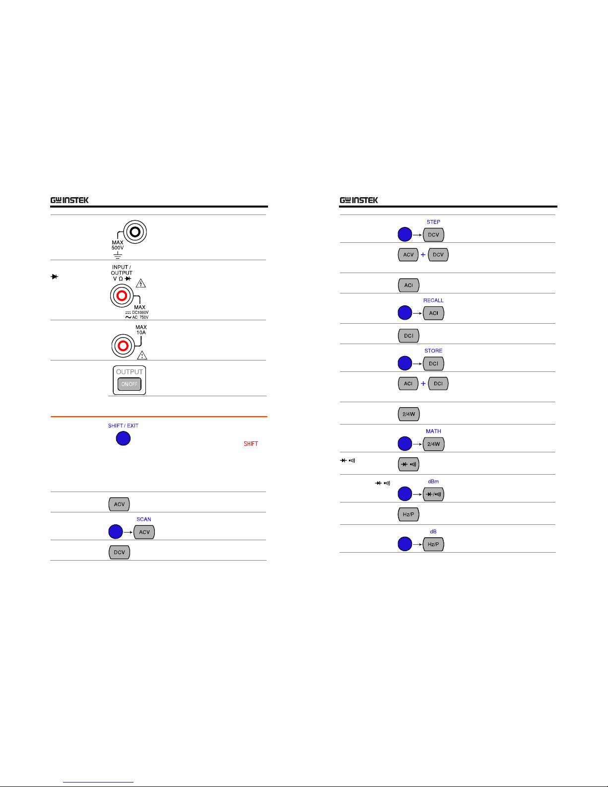
12
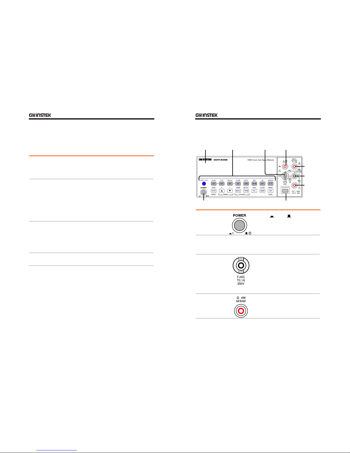
Front Panel Overview
Measurement
key
Main
Terminal
4W Ohm
Terminal
Fuse
Power Switch
Main
Display
DCI/ACI
Terminal
Output
On/Off key
COM
Terminal
Power Switch
Turns O n or Off the main power.
For power up sequence, see page20.
Main Display
Shows measurement results and parameters.
For display configuration details, see page64 (light
setting).
Input fuse / 4W
Ω sense LO
terminal
As a fuse, protects the instrument from
over-current. Rating: T0.1A, 250V.
For fuse replacement procedure, see
page108.
As a sense terminal, accepts 4W Ω
measurement LO connection. For
details, see page30.
4W Ω Sense HI
Term in al
Accepts HI sense line in 4W resistance
measurement. For details, see page30.
GETTING STARTED
13
COM Terminal
Accepts ground (COM) line in all
measurements except the sense line in
4W Resistance (page30).
Voltag e/ 2W Ω /
(Diode)
Term in al
Accepts input in all measurements
except for DC/AC Current and 4W
Resistance sense line.
Current Terminal
Accepts DC/AC Current input.
For DCI/ACI details, see page28.
Output On/Off
key (Reserved)
Reserved for the future use in the
optional Power source module.
Measurement keys (Upper row)
SHIFT/EXIT
As the Shift key, selects the second
functionality assigned to each front
panel key. When pressed, the
indicator appears in the display.
As the Exit key, gets out of the
parameter configuration mode and
goes back to the measurement result
display mode.
ACV
Measures AC Voltage (page24).
SHIFT → ACV
(SCAN)
Starts the optional scan measurement
(page76).
DCV
Measures DC Voltage (page24).
GDM-8200 Series User Manual
14
SHIFT → DCV
(STEP)
Starts the step measurement (page76)
using the optional scanner.
ACV + DCV
When the ACV key and the DCV key
are pressed together, they measure
AC+DC Voltage (page24).
ACI
Measures AC Current (page28).
SHIFT → ACI
(RECALL)
Recalls a normal measurement result
(page66) or a scan measurement
result (page83).
DCI
Measures DC Current (page28).
SHIFT → DCI
(STORE)
Stores a measurement result
(page65).
ACI + DCI
When the ACI key and the DCI key
are pressed together, they measure
AC+DC Current (page28).
2/4W
(Resistance)
Measures 2-wire or 4-wire Resistance
(page30).
SHIFT → 2/4W
(MATH)
Enters the Math measurement mode
(page52).
/
(Diode/
Continuity)
/
Tests Diode (page32) or Continuity
(page33).
SHIFT → /
(dBm)
Measures dBm (page43).
Hz/P (Frequency/
Period)
Measures Frequency or Period
(page36).
SHIFT + Hz/P
(dB)
Measures dB (page44).
GETTING STARTED
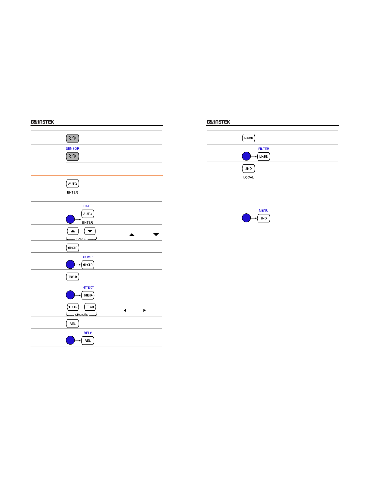
15
°C/°F
(Temperature)
Measures Temperature (page37).
SHIFT + °C/°F
(SENSOR)
Selects the type of thermocouple
used in the Temperature
measurement (page38).
Measurement keys (Lower row)
AUTO/ENTER
As the AUTO key, selects the
measurement range automatically.
As the ENTER key, confirms the
entered value.
SHIFT → AUTO
(RATE)
Selects the measurement update rate:
Slow, Medium, or Fast (page22).
Up/Down
Selects the parameter in various
occasions: higher (
) or lower ( ).
HOLD
Activates the Hold function (page48).
SHIFT → HOLD
(COMPare)
Activates the Compare measurement
(page49).
TRIG (Trigger)
Triggers sample acquisition manually
(page59).
SHIFT → TRIG
(Int/Ext Trigger)
Selects the Internal or the External
trigger source (page59).
Left/Right
Selects the parameter in various
occasions: left (
) or right ( ).
REL
Measures the Relative value (page46).
SHIFT → REL
(RELative base)
Manually sets the reference value for
the Relative value measurement
(page46).
GDM-8200 Series User Manual
16
MX/MN
(MAX/ MIN)
Measures the Maximum or the
Minimum value (page45).
SHIFT →
MX/MN (FILTER)
Selects the digital filter type for the
signal sampling (page62).
2ND (Display) /
LOCAL
As the 2nd key, selects the
measurement item on the 2
nd
display
(page56). Pressing and holding for
more than 1 second turns off the 2
nd
display.
As the Local key, releases the remote
control and goes back to the local
panel operation (page91).
SHIFT → 2ND
(Menu)
Enters the configuration mode.
Configures or displays the following
items: Display (page57), Beep
(page35), Continuity threshold
(page34), Scanner (page76), Digital
I/O (page85), and System
information (page105).
GETTING STARTED
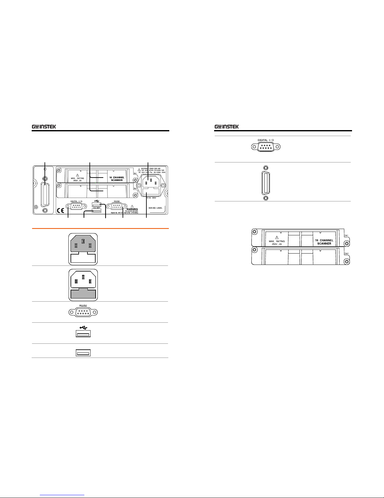
17
Rear Panel Overview
GPIB Port
(Optional)
RS-232C
Port
Optional Item
Slot x2
Power Cord
Socket
Fuse
T3.15A/250V
CAL Key
Port
Digital I/O
Port
USB Host
Port
Power Cord
Socket
Accepts the power cord. AC
100–240V, 50–60Hz.
For power on sequence, see page20.
Fuse Socket
Holds the main fuse: T3.15A 250V,
20VA.
For fuse replacement details, see
page107.
RS-232C port
Accepts an RS-232C cable for remote
control; DB-9 male connector.
For remote control details, see page92.
USB host port
Accepts a USB host cable for remote
control; Type A, male connector.
For remote control details, see page91.
CAL key port
CAL KEY
Reserved for internal uses as in
firmware update and calibration.
GDM-8200 Series User Manual
18
Digital I/O port
Accepts a digital I/O cable for the
Hi/Lo limit test; DB-9 pin, female
connector.
For digital I/O details, see page86.
GPIB port
(optional)
Factory installed optional GPIB
interface. Accepts a GPIB cable for
remote control; 24 pin, female.
For remote control details, see page93.
Optional slot x2
Accepts up to two optional scanner modules. 16
channels are available per scanner. When two modules
are used, maximum 32 channels are available.
For scanner details, see page68.
GETTING STARTED
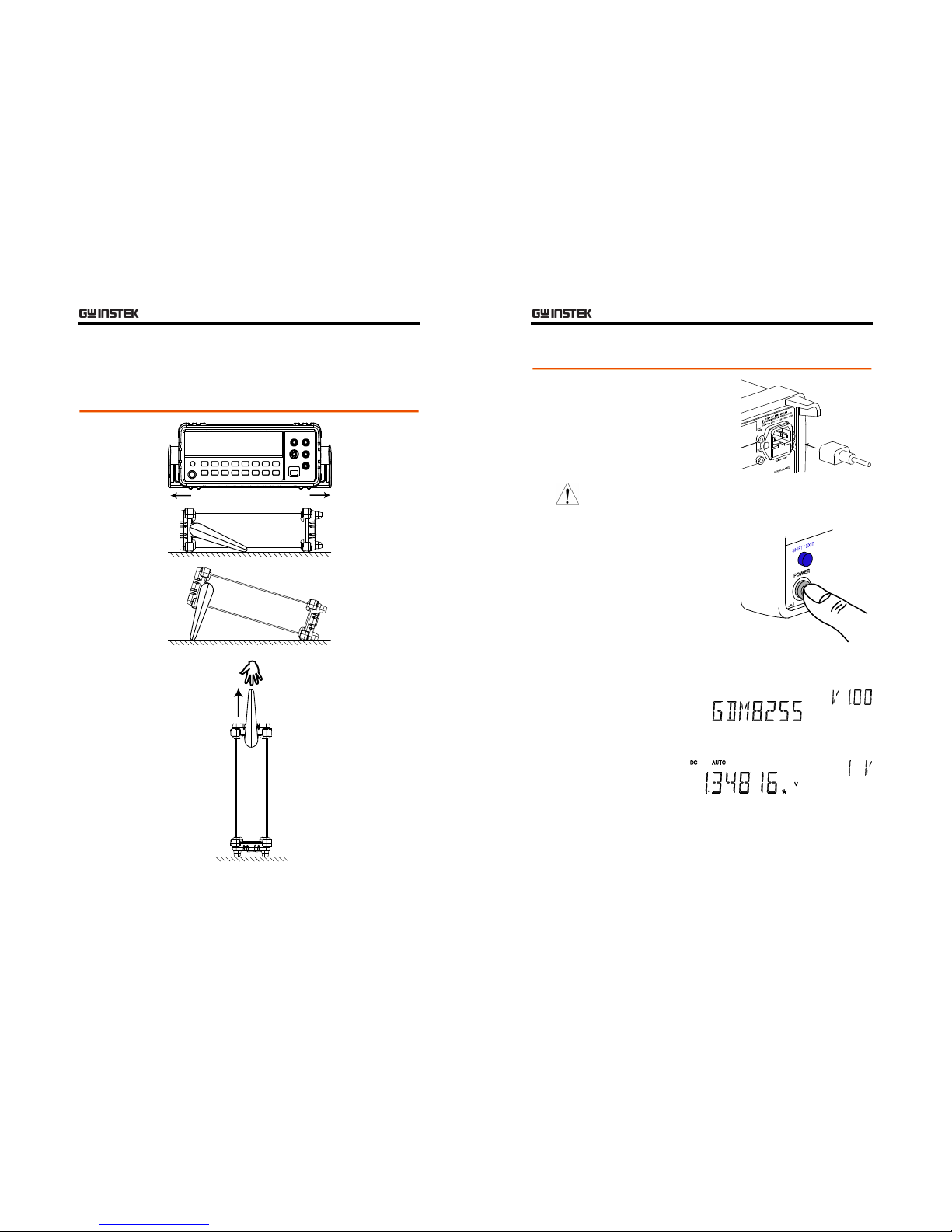
19
Set Up
Tilt Stand
Tilt stand steps
Pull out the
handle sideways
and rotate it.
Place the unit
horizontally,
Or in the tilt
stand position.
Place the handle
vertically for hand
carry.
GDM-8200 Series User Manual
20
Power Up
Power up steps
1. Connect the power
cord to the AC
Voltage input.
Note
Make sure the ground connector of the power cord
is connected to a safety ground. This will affect the
measurement accuracy.
2. Push and turn On the
main power switch on
the front panel.
3. The display shows the model name and the version
for a few seconds.
Example: GDM-8255, V1.0
4. Then the default setting appears.
Example: DCV, Auto, 1V range
BASIC MEASUREMENT
21
BASIC MEASUREMENT
Overview Basic Measurement Overview ................................22
Common attribute: refresh rate..............................22
Common attribute: reading indicator .....................23
Common attribute: manual/automatic triggering ..23
Voltage AC/DC/AC+DC Voltage Measurement....................24
Select Voltage range...............................................25
Voltage conversion table ........................................26
Crest factor table....................................................27
Current AC/DC/AC+DC Current Measurement ...................28
Select Current range...............................................29
Resistance 2W/4W Resistance Measurement...........................31
Diode Diode Test ..............................................................33
Continuity Continuity Test .......................................................33
Set continuity threshold .........................................34
Select beeper setting ..............................................35
Freque ncy/
Period
Frequency/Period Measurement.............................36
Temperature Temperature Measurement ....................................37
Select thermocouple type .......................................38
Set reference junction temperature ........................39
GDM-8200 Series User Manual
22
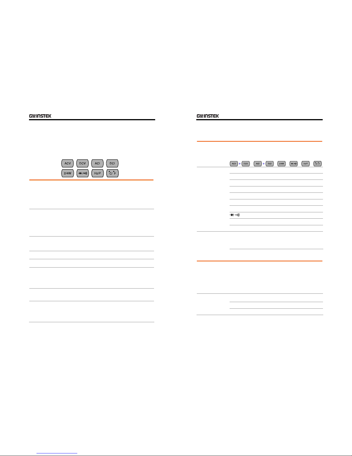
Basic Measurement Overview
Background
Basic measurement refers to the eight types of
measurements assigned to the upper row keys on the
front panel.
Measurement type ACV
AC Voltage
DCV
DC Voltage
ACV+DCV
AC+DC Voltage
ACI
AC Current
DCI
DC Current
ACI+DCI
AC+DC Current
2/4W
2-wire and 4-wire Resistance
Diode/Continuity
Hz/P
Frequency/Period
°C/°F
Celsius/Fahrenheit Temperature
Advanced
measurement
Advanced measurement (page40) mainly refers to the
operation using the result obtained from one or more of
the basic measurement.
Common attribute: refresh rate
Background
Refresh rate defines how frequently GDM-8200 series
captures and updates the measurement data. Faster
refresh rate yields better accuracy but lower resolution.
Slower refresh rate yields lower accuracy but higher
resolution. Consider these trade-offs when selecting the
refresh rate.
Range S
5 ½ digits
M
4 ½ digits
F
3 ½ digits
BASIC MEASUREMENT
23
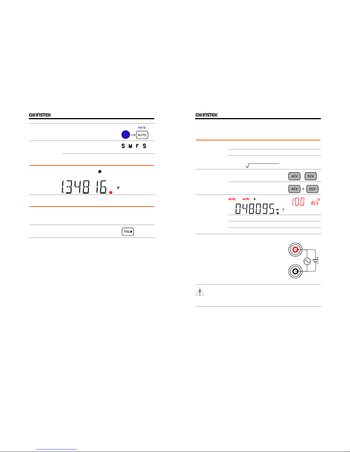
Selection step
1. Press the Shift key followed by
the AUTO (RATE) key. The
refresh rate switches to the next.
2. The refresh rate indicator shows
the current status.
→ → →
Common attribute: reading indicator
Background
The reading indicator next to the 1st display flashes
according to the refresh rate setting.
Common attribute: manual/automatic triggering
Automatic
triggering
(default)
GDM-8200 series triggers according to the refresh rate.
See the previous page for refresh rate setting details.
Manual
triggering
Press the TRIG key to trigger
measurement manually.
GDM-8200 Series User Manual
24
AC/DC/AC+DC Voltage Measurement
Vol tage typ e AC (true RM S)
0 ~ 750V
DC
0 ~ 1000V
AC+DC
0 ~ 1000V
(AC RMS)2+(DC)
2
*AC+DC=
1. Activate ACV/
DCV
Press the ACV (AC Voltage) key or
DCV (DC Voltage) key.
or
For AC+DC Voltage, press the ACV
key and the DCV key together.
2. ACV/DCV
mode display
appears
AC(DC) + V Indicates AC, DC, AC+DC Voltage
AUTO Indicates Automatic range selection
100mV 2nd display shows the Voltage range
3. Connect the
test lead and
measure
Connect the test lead between the V
and the COM port. The display
updates the reading.
V
COM
Note
When measuring in1000V (maximum) range immediately
followed by 100uV (minimum) range, an error might
occur due to extreme range switching. In such case, take
at least one minute in between as an interval.
BASIC MEASUREMENT
25
Select Voltage range
Auto range
To turn the automatic range selection
On/Off, press the AUTO key.
Manual range
Press the Up or the Down key to select
the range. AUTO indicator turns Off
automatically. If the appropriate range
is unknown, select the highest range.
Resolution / Full scale @ slow rate Selection list Range
Resolution Full scale
(GDM-8251)
Full scale
(GDM-8255)
100mV
1µV 120.000mV 199.999mV
1V
10µV 1.20000V 1.99999V
10V
100µV 12.0000V 19.9999V
100V
1mV 120.000V 199.999V
750V (AC)
10mV 750.0V 750.0V
1000V
(DC, AC+DC)
10mV 1000.0V 1000.0V
Note
For more detailed parameters, see the specification at
page109.
GDM-8200 Series User Manual
26
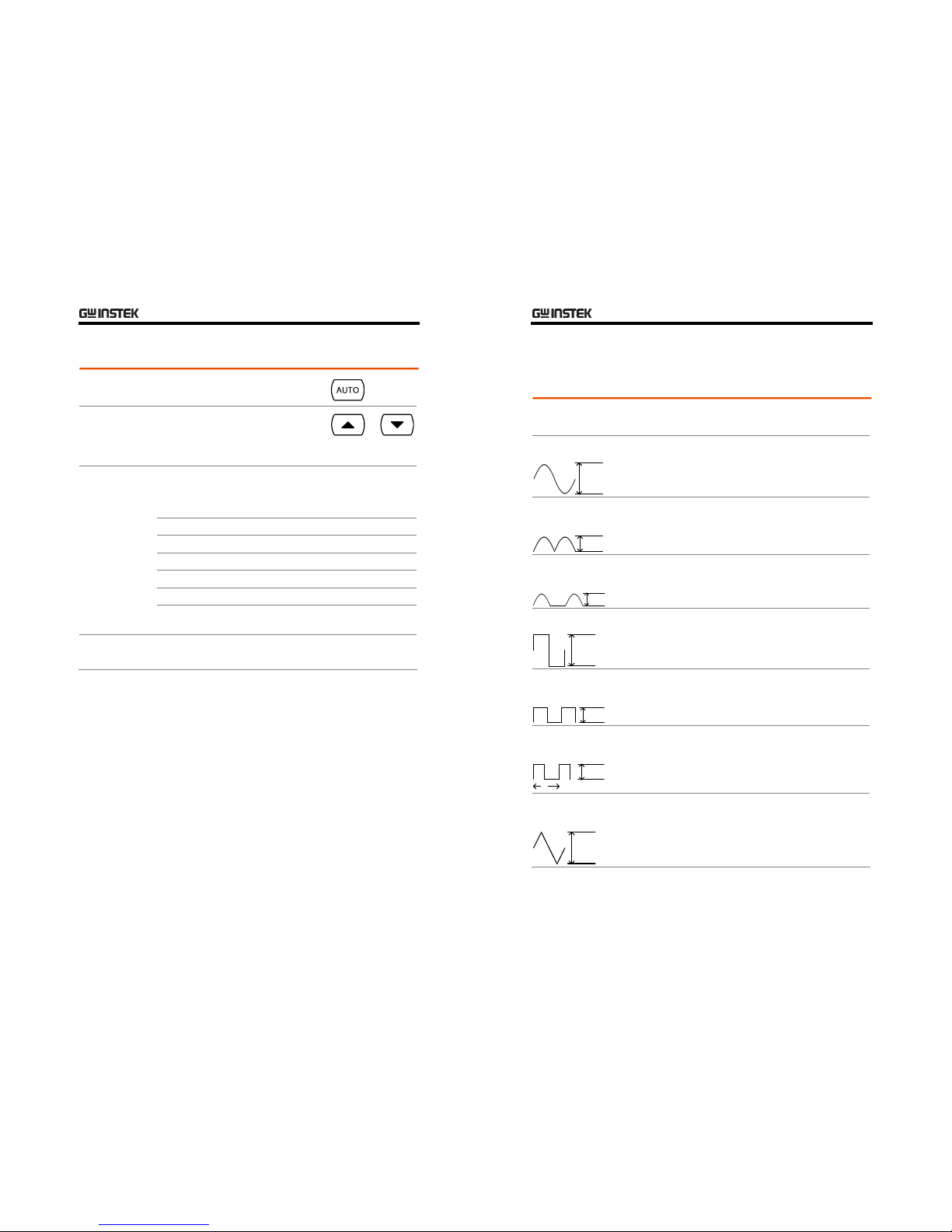
Voltage conversion table
This table shows the relationship between AC, DC, and AC+DC reading in
various wavefor ms.
Waveform Peak to Peak AC
(True RMS)
DC AC + DC
(True RMS)
Sine
PK-PK
2.828 1.000 0.000 1.000
Rectified Sine
(full wave)
PK-PK
1.414 0.435 0.900 1.000
Rectified Sine
(half wave)
PK-PK
2.000 0.771 0.636 1.000
Square
PK-PK
2.000 1.000 0.000 1.000
Rectified
Square
PK-PK
1.414 0.707 0.707 1.000
Rectangular
Pulse
PK-PK
X
Y
2.000 2K
K=√( D-D
2
)
D=X/Y
2D
D=X/Y
2√D
D=X/Y
Tria ng le
Sawtooth
PK-PK
3.464 1.000 0.000 1.000
BASIC MEASUREMENT
27
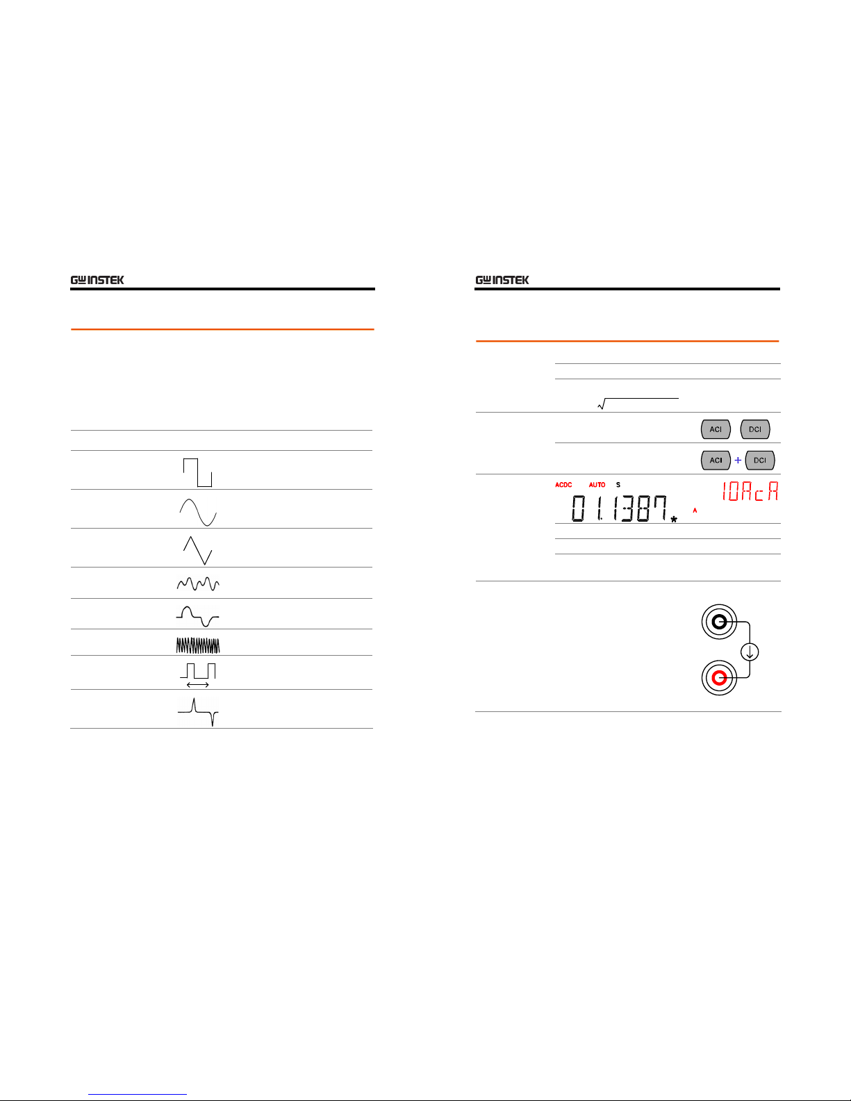
Crest factor table
Background
Crest factor is the ratio of the peak signal amplitude to the
RMS value of the signal. It determines the accuracy of AC
measurement.
If the crest factor is less than 3.0, voltage measurement will
not result in error due to dynamic range limitations at full
scale.
If the crest factor is more than 3.0, it usually indicates
abnormal waveform as seen from the below table.
Waveform Shape Crest factor
Square wave
1.0
Sine wave
1.414
Tr ia ng le
sawtooth
1.732
Mixed
frequencies
1.414 ~ 2.0
SCR output
100% ~ 10%
1.414 ~ 3.0
White noise
3.0 ~ 4.0
AC Coupled
pulse train
3.0
Spike
>9.0
GDM-8200 Series User Manual
28
AC/DC/AC+DC Current Measurement
Current type AC (true RMS)
0 ~ 10A
DC
0 ~ 10A
AC+DC
0 ~ 10A
(AC RMS)2+(DC)
2
*AC+DC=
1. Activate ACV/
DCV
Press the ACI (AC Current) key or
the DCI (DC Current) key.
or
For AC+DC Current, press the ACI
key and the DCI key together.
2. ACI/DCI mode
display appears
AC(DC) + A Indicates AC, DC, AC+DC Current
AUTO Indicates Automatic range selection
10acA 2nd display shows the Current range
10A breaks into 10acA (AC) or 10dcA (DC)
3. Connect the
test lead and
measure
Connect the test lead between the A
and COM port. The display updates
the reading.
A
COM
BASIC MEASUREMENT
29
Select Current range
Auto range
To turn the automatic range selection
On/Off, press the AUTO key.
Manual range
Press the Up or the Down key to select
the range. AUTO indicator turns Off
automatically. If the appropriate range
is unknown, select the highest range.
Resolution / Full scale @ slow rate Selection list Range
Resolution Full scale
(GDM-8251)
Full scale
(GDM-8255)
10mA
0.1µA 12.0000mA 19.9999mA
100mA
1µA 100.000mA 100.000mA
10A
100µA 10.0000A 10.0000A
Note
*10A range is not available for AC+DC Current.
For more detailed range, see the specification at page111.
GDM-8200 Series User Manual
30
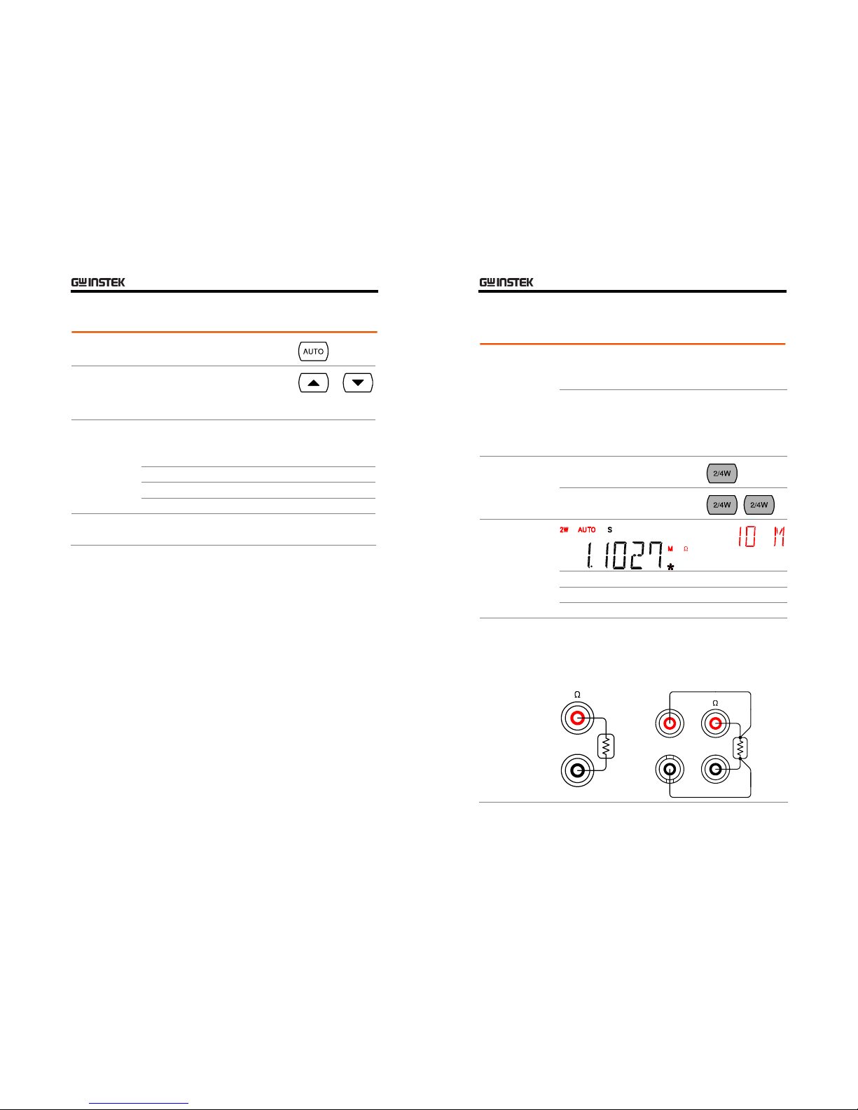
2W/4W Resistance Measurement
Measurement
type
2-wire
Uses the standard V-COM ports.
Recommended for measuring resistances
larger than 1kΩ.
4-wire
Compensates the test lead effect using the
4W compensation ports,, in addition to the
standard V-COM ports.
Recommended for measuring sensitive
resistances smaller than 1kΩ.
For 2-wire resistance measurement,
press the 2W/4W key once.
1. Activate
resistance
measurement
For 4-wire resistance measurement,
press the 2W/4W key twice.
2. 2W resistance
mode display
appears
2W(4W) + Ω
Indicates 2W(4W) Resistance
AUTO Indicates Automatic range selection
10M 2nd display shows the Resistance range
3. Connect the
test lead and
measure
Connect the test lead. For 2-wire resistance, use the V
and the COM port. For 4-wire resistance, use the V and
the COM port, plus the 4W sense, and LO port for
sensing. The display updates the reading.
2W connection
COM
4W connection
COM
4W
SENSE
LO
BASIC MEASUREMENT
31
Select Resistance range
Auto range
To turn the automatic range selection
On/Off, press the AUTO key.
Manual range
Press the Up or the Down key to select
the range. AUTO indicator turns Off
automatically. If the range is unknown,
select the highest range.
Selection list Range Full scale @ slow rate
GDM-8251 GDM-8255
100Ω
120.000Ω 199.999Ω
1kΩ
1.2000kΩ 1.9999kΩ
10kΩ
12.0000kΩ 19.9999kΩ
100kΩ
120.000kΩ 199.999kΩ
1MΩ
1.20000MΩ 1.99999MΩ
10MΩ
12.0000MΩ 19.9999MΩ
100MΩ
120.000MΩ 199.999MΩ
Note
For more detailed range, see the specification at page112.
GDM-8200 Series User Manual
32
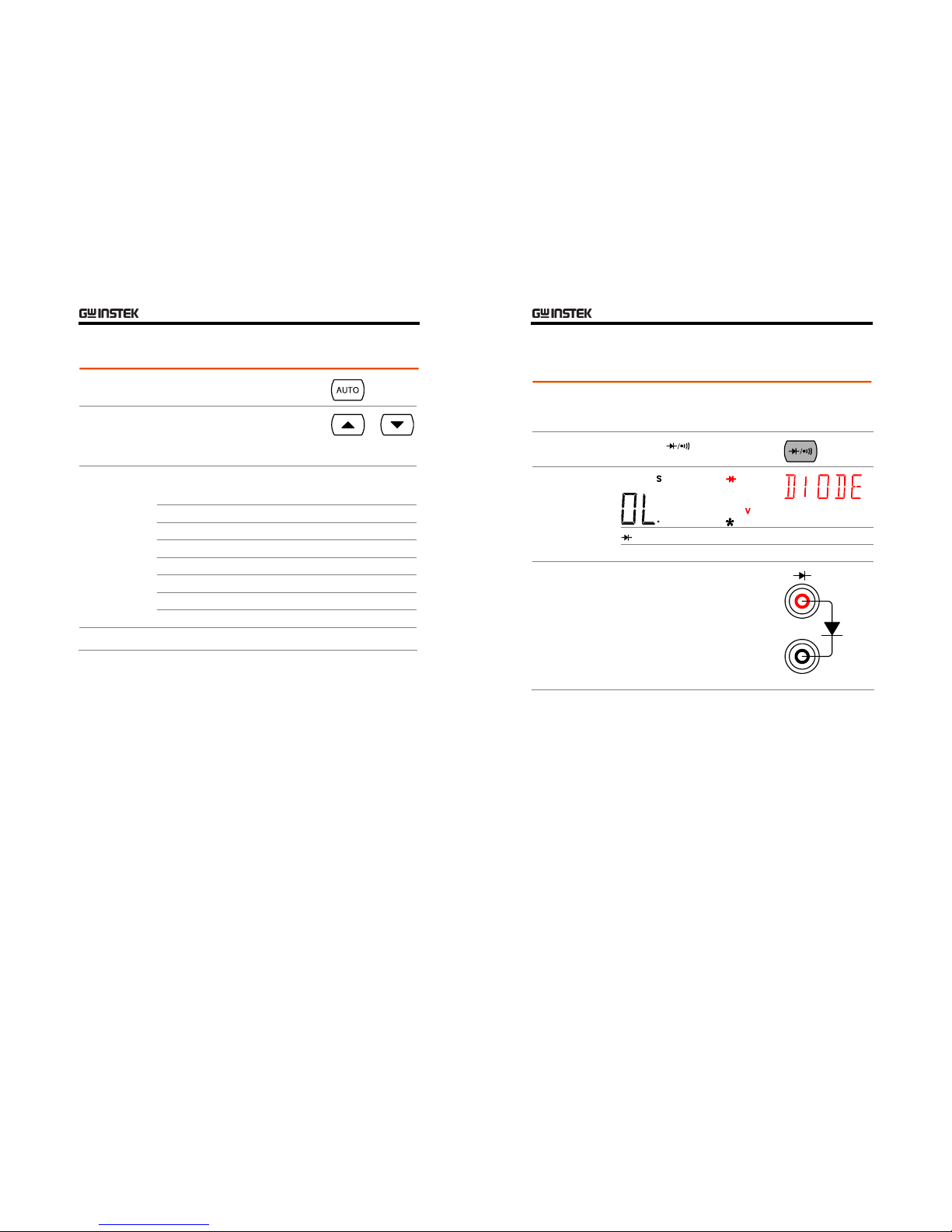
Diode Test
Background
Diode test checks the forward bias characteristics of a
diode by running a constant forward bias current, 2mA,
through the DUT.
1. Activate diode
test
Press the key once.
2. Diode mode
display appears
+ V Indicates Diode test
DIODE 2nd display shows the title
3. Connect the
test lead and
measure
Connect the test lead between the V
and COM port; Anode-V,
Cathode-COM. The display updates
the reading.
COM
BASIC MEASUREMENT
33
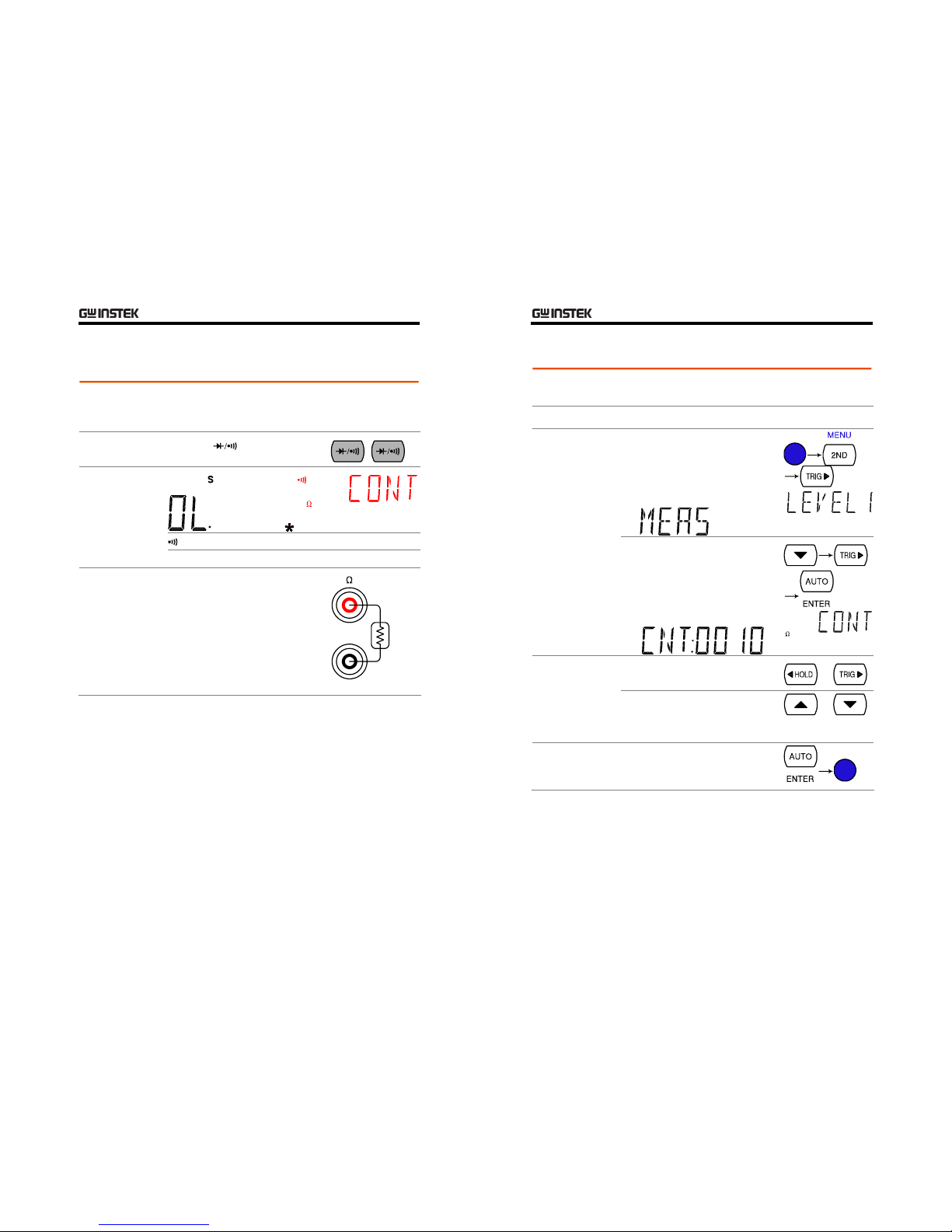
Continuity Test
Background
Continuity test checks that the resistance in the DUT is
low enough to be considered continuous (of conductive
nature).
1. Activate
continuity test
Press the key twice.
2. Continuity
mode display
appears
+ Ω
Indicates Continuity test
CONT 2nd display shows the title
3. Connect the
test lead and
measure
Connect the test lead between the V
and the COM port. The display
updates the reading.
COM
GDM-8200 Series User Manual
34
Set continuity threshold
Background
Continuity threshold defines the maximum resistance
allowed in the DUT when testing the continuity.
Threshold Range
0 ~ 1000Ω, 1Ω resolution, 10Ω default
1. Activate
threshold setting
1. Press the Shift key, the 2ND key,
the Right key. The measurement
menu appears.
2. Press the Down key, the Right
key, the Enter key. The
continuity threshold setting
appears.
2. Edit threshold
1. Move the cursor (the flashing
digit) using the Left/Right key.
2. Change the value using the
Up/Down key.
Range:
1 ~ 1000Ω, 1Ω resolution, default 10Ω
3. Go back to the
default display
Press the Enter key to confirm the
edited threshold. Press the Exit key
to go back to the default display.
BASIC MEASUREMENT
35
Select beeper setting
Background
Beeper setting defines how GDM-8200 series notifies the
continuity test result to the user.
Pass
Beeps when the test result is pass
Beeper
parameter
Fai l
Beeps when the test result is fail
Off
Beep function is turned Off
1. Activate
beeper setting
menu
1. Press the Shift key followed by
the 2nd (Menu) key. The system
menu appears.
2. Press the Down key followed by
the Right key. The beep menu
appears.
3. Press the Down key. The beep
setting appears.
2. Select the
beep setting
To change the setting, press the
Left/Right key.
Beeper type:
Pass (beep when pass), Fail (beep when
fail, default), Off (beep off)
3. Go back to the
default display
Press the Enter key to confirm.
Press the Exit key to go back to the
default display.
GDM-8200 Series User Manual
36
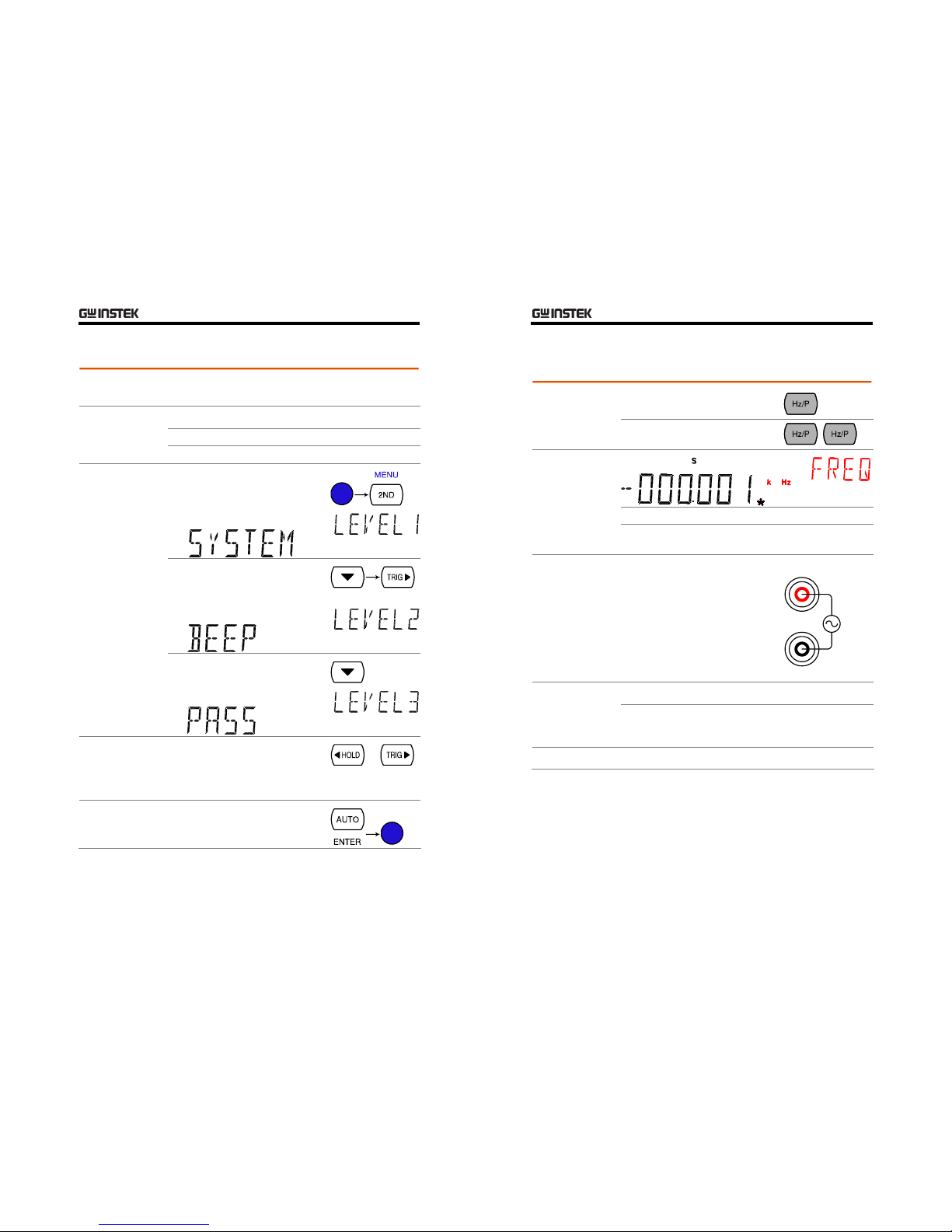
Frequency/Period Measurement
To measure Frequency, press the
Hz/P key once.
1. Activate
frequency/period
measurement
To measure Period, press the Hz/P
key twice.
2. Frequency
(Period) mode
display appears
Hz (S) Indicates Frequency (period) measurement
FREQ
(PERIOD)
2nd display shows the title
3. Connect the
test lead and
measure
Connect the test lead between the V
and the COM port. The display
updates the reading.
V
COM
10Hz ~ 800kHz
Frequency range
Sensitivity 10Hz ~ 100kHz: >0.1V
100kHz ~ 600kHz: >1.0V
600kHz ~ 800kHz: >2.5V
Period Range
1.25µs ~ 0.1s
 Loading...