

Page 1

Digital Multimeter
GDM-8200A Series
USER MANUAL
GW INSTEK PART NO. 82DM-8255AE E1
ISO-9001 CERTIFIED MANUFACTURER
Page 2

March 2013
This manual contains proprietary information, which is protected by
copyrights. All rights are reserved. No part of this manual may be
photocopied, reproduced or translated to another language without
prior written consent of Good Will company.
The information in this manual was correct at the time of printing.
However, Good Will continues to improve products and reserves
the right to change specifications, equipment, and maintenance
procedures at any time without notice.
Good Will Instrument Co., Ltd.
No. 7-1, Jhongsing Rd., Tucheng Dist., New Taipei City 236, Taiwan.
Page 3

Table of Contents
Table of Contents
SAFETY INSTRUCTIONS .................................................... 5
Safety Symbols .................................................... 5
Safety Guidelines ................................................ 6
GETTING STARTED ............................................................ 9
GDM-8200A Series Lineup ................................ 10
GDM-8200A Series Characteristics ................... 11
Front Panel Overview ........................................ 12
Rear Panel Overview ......................................... 17
Set Up ............................................................... 19
BASIC MEASUREMENT .................................................... 21
Basic Measurement Overview ........................... 22
AC/DC/AC+DC Voltage Measurement .............. 24
AC/DC/AC+DC Current Measurement .............. 28
2W/4W Resistance Measurement ..................... 30
Diode Test ......................................................... 32
Continuity Test .................................................. 33
Frequency/Period Measurement ....................... 36
Temperature Measurement ............................... 37
ADVANCED MEASUREMENT ........................................... 40
Advanced Measurement Overview .................... 41
dBm/dB Measurement ...................................... 43
Max/Min Measurement..................................... 45
Relative Value Measurement ............................. 46
Hold Measurement ........................................... 48
Compare Measurement ..................................... 49
Math Measurement ........................................... 52
Dual Display Measurement ............................... 55
SYSTEM/DISPLAY CONFIGURATION .............................. 57
Refresh Rate Setting .......................................... 58
Trigger Setting ................................................... 59
3
Page 4

GDM-8200A Series User Manual
Digital Filter Setting .......................................... 62
Display Setting .................................................. 64
STORE/RECALL ............................................................... 66
Store Measurement Record ............................... 67
Recall Measurement Record .............................. 68
Save Instrument Settings .................................. 69
Recall Instrument Settings ................................ 70
SCANNER (OPTIONAL) .................................................. 71
GDM-SC1 Scanner Specifications ..................... 72
Scanner Installation .......................................... 72
Setup Scan ........................................................ 80
Run Scan ........................................................... 87
DIGITAL I/O .................................................................... 90
Digital I/O Terminal Configuration ................... 91
REMOTE CONTROL ........................................................ 95
Configure Interface ............................................ 96
Command Syntax .............................................. 99
Command Set .................................................. 100
FAQ ................................................................................ 109
APPENDIX ...................................................................... 110
Firmware Version ............................................ 111
Fuse Replacement ........................................... 112
Specifications .................................................. 114
EC Declaration of Conformity .......................... 121
INDEX ............................................................................ 122
4
Page 5
SAFETY INSTRUCTIONS
WARNING
Warning: Identifies conditions or practices that could
result in injury or loss of life.
CAUTION
Caution: Identifies conditions or practices that could
result in damage to the GDM-8200A series or to other
properties.
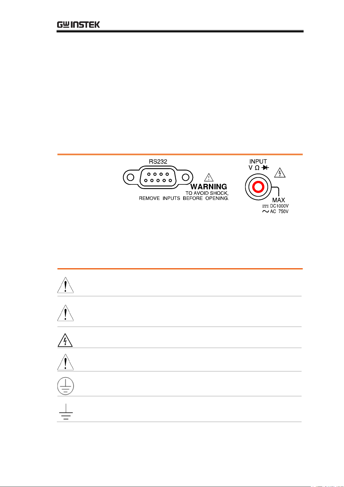
DANGER High Voltage
Attention Refer to the Manual
Protective Conductor Terminal
Earth (ground) Terminal
SAFETY INSTRUCTIONS
This chapter contains important safety instructions that
you must follow when operating the GDM-8200A series
and when keeping them in storage. Read the following
before any operation to insure your safety and to keep
the best condition for the GDM-8200A series.
Safety Symbols
These safety symbols may appear in this manual or on the GDM-8200A
series.
5
Page 6
GDM-8200A Series User Manual
General Guideline
CAUTION
Make sure that the voltage input level does not exceed
DC1000V/AC750V.
Make sure the current input level does not exceed 10A.
Do not place any heavy object on the GDM-8200A
series.
Avoid severe impacts or rough handling that leads to
damaging the GDM-8200A series.
Do not discharge static electricity to the GDM-8200A
series.
Use only mating connectors, not bare wires, for the
terminals.
Do not block or obstruct the cooling fan vent opening.
Do not perform measurement at the source of
low-voltage installation or at building installations
(Note below).
Do not disassemble the GDM-8200A series unless you
are qualified as service personnel.
(Note) EN 61010-1:2001 specifies the measurement categories and
their requirements as follows. The GDM-8200A series fall under
category I or II.
Measurement category IV is for measurement performed at the
source of low-voltage installation.
Measurement category III is for measurement performed in the
building installation.
Measurement category II is for measurement performed on the
circuits directly connected to the low voltage installation.
Measurement category I is for measurements performed on circuits
not directly connected to Mains.
Power Supply
WARNING
AC Input voltage: 100–240 V AC, 50–60Hz
The power supply voltage should not fluctuate more
than 10%.
Connect the protective grounding conductor of the
AC power cord to an earth ground, to avoid electrical
shock.
Safety Guidelines
6
Page 7

SAFETY INSTRUCTIONS
Fuse
WARNING
Fuse type: T3.15A/ 250V
Make sure the correct type of fuse is installed before
power up.
To ensure fire protection, replace the fuse only with
the specified type and rating.
Disconnect the power cord before fuse replacement.
Make sure the cause of fuse blowout is fixed before
fuse replacement.
Cleaning the
GDM-8200A series
Disconnect the power cord before cleaning.
Use a soft cloth dampened in a solution of mild
detergent and water. Do not spray any liquid into the
GDM-8200A series.
Do not use chemical or cleaner containing harsh
material such as benzene, toluene, xylene, and acetone.
Operation
Environment
Location: Indoor, no direct sunlight, dust free, almost
non-conductive pollution (Note below)
Relative Humidity: < 75%
Altitude: < 2000m
Temperature: 0°C to 40°C (operation), 18°C to 28°C
(full accuracy)
(Note) EN 61010-1:2001 specifies the pollution degrees and their
requirements as follows. the GDM-8200A series falls under degree
2.
Pollution refers to “addition of foreign matter, solid, liquid, or
gaseous (ionized gases), that may produce a reduction of dielectric
strength or surface resistivity”.
Pollution degree 1: No pollution or only dry, non-conductive pollution
occurs. The pollution has no influence.
Pollution degree 2: Normally only non-conductive pollution occurs.
Occasionally, however, a temporary conductivity caused by
condensation must be expected.
Pollution degree 3: Conductive pollution occurs, or dry,
non-conductive pollution occurs which becomes conductive due to
condensation which is expected. In such conditions, equipment is
normally protected against exposure to direct sunlight, precipitation,
and full wind pressure, but neither temperature nor humidity is
controlled.
Storage
Environment
Location: Indoor
Relative Humidity: < 75% (0~35°C), <50% (35~50°C)
Temperature: −10°C to 70°C
7
Page 8
GDM-8200A Series User Manual
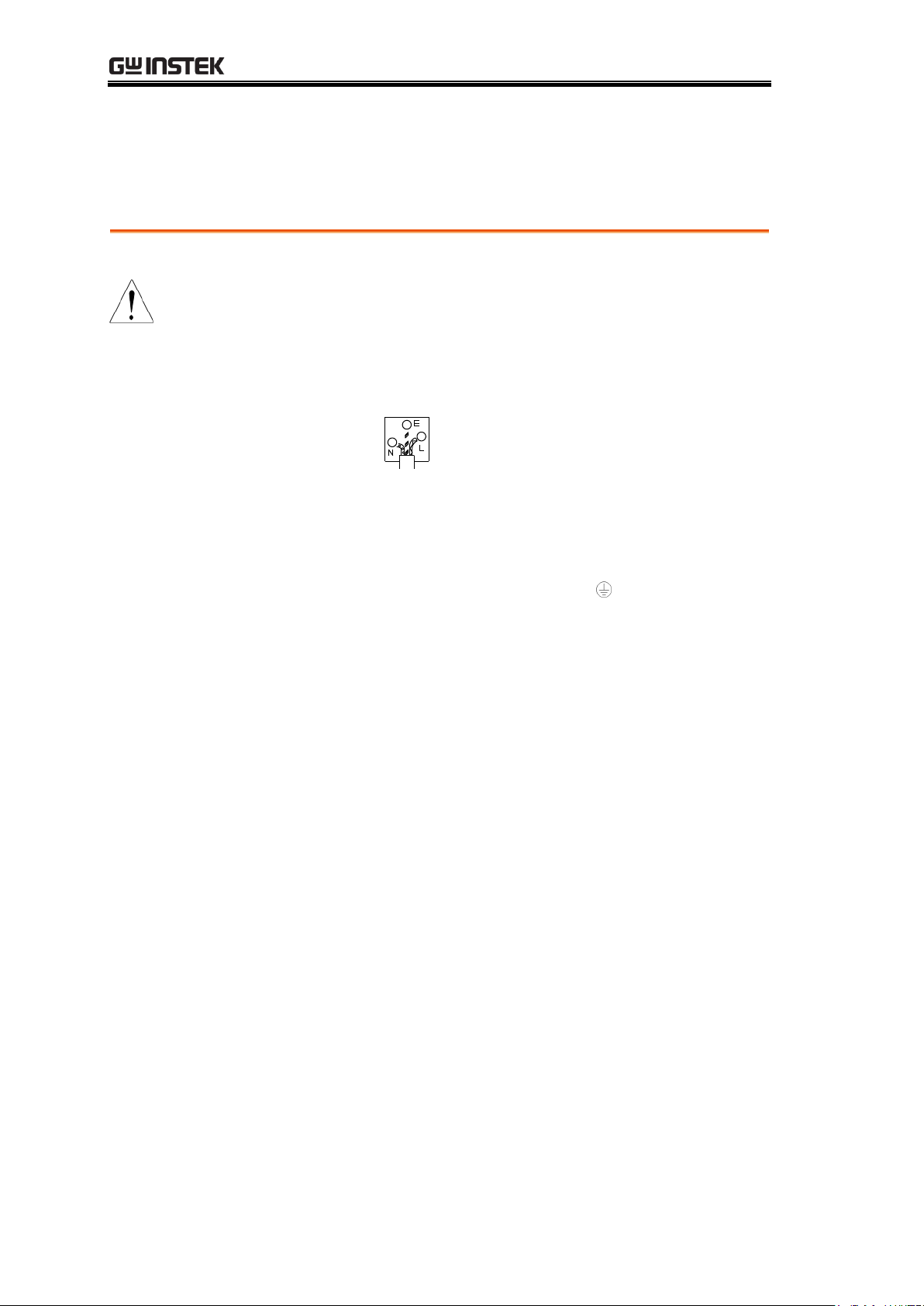
Green/ Yellow:
Earth
Blue:
Neutral
Brown:
Live (Phase)
Power cord for the United Kingdom
When using the GDM-8200A series in the United Kingdom, make sure the
power cord meets the following safety instructions.
NOTE: This lead / appliance must only be wired by competent persons
WARNING: THIS APPLIANCE MUST BE EARTHED
IMPORTANT: The wires in this lead are coloured in accordance with the
following code:
As the colours of the wires in main leads may not correspond with the
colours marking identified in your plug/appliance, proceed as follows:
The wire which is coloured Green & Yellow must be connected to the Earth
terminal marked with the letter E or by the earth symbol or coloured Green
or Green & Yellow.
The wire which is coloured Blue must be connected to the terminal which is
marked with the letter N or coloured Blue or Black.
The wire which is coloured Brown must be connected to the terminal marked
with the letter L or P or coloured Brown or Red.
If in doubt, consult the instructions provided with the equipment or contact
the supplier.
This cable/appliance should be protected by a suitably rated and approved
HBC mains fuse: refer to the rating information on the equipment and/or
user instructions for details. As a guide, cable of 0.75mm2 should be protected
by a 3A or 5A fuse. Larger conductors would normally require 13A types,
depending on the connection method used.
Any moulded mains connector that requires removal /replacement must be
destroyed by removal of any fuse & fuse carrier and disposed of immediately,
as a plug with bared wires is hazardous if a engaged in live socket. Any
re-wiring must be carried out in accordance with the information detailed on
this label.
8
Page 9
GETTING STARTED
Characteristics
GDM-8200A Series Lineup ..................................... 10
GDM-8200A Series Characteristics ......................... 11
Panel Overview
Front Panel Overview ............................................. 12
Measurement keys (Upper row) ............................. 13
Measurement keys (Lower row) ............................. 15
Rear Panel Overview .............................................. 17
Setup
Tilt Stand ................................................................ 19
Power Up ................................................................ 20
GETTING STARTED
This chapter describes the GDM-8200A series in a
nutshell, including its main features, package contents,
and front / rear / display panel introduction. After going
through the overview, follow the Power-up sequence and
Functionality check section to properly setup the
GDM-8200A series.
Please note the information in this manual was correct at
the time of printing. However as GWInstek continues to
improve its products, changes can occur at any time
without notice. Please see the GWInstek website for the
latest information and content.
9
Page 10
GDM-8200A Series User Manual
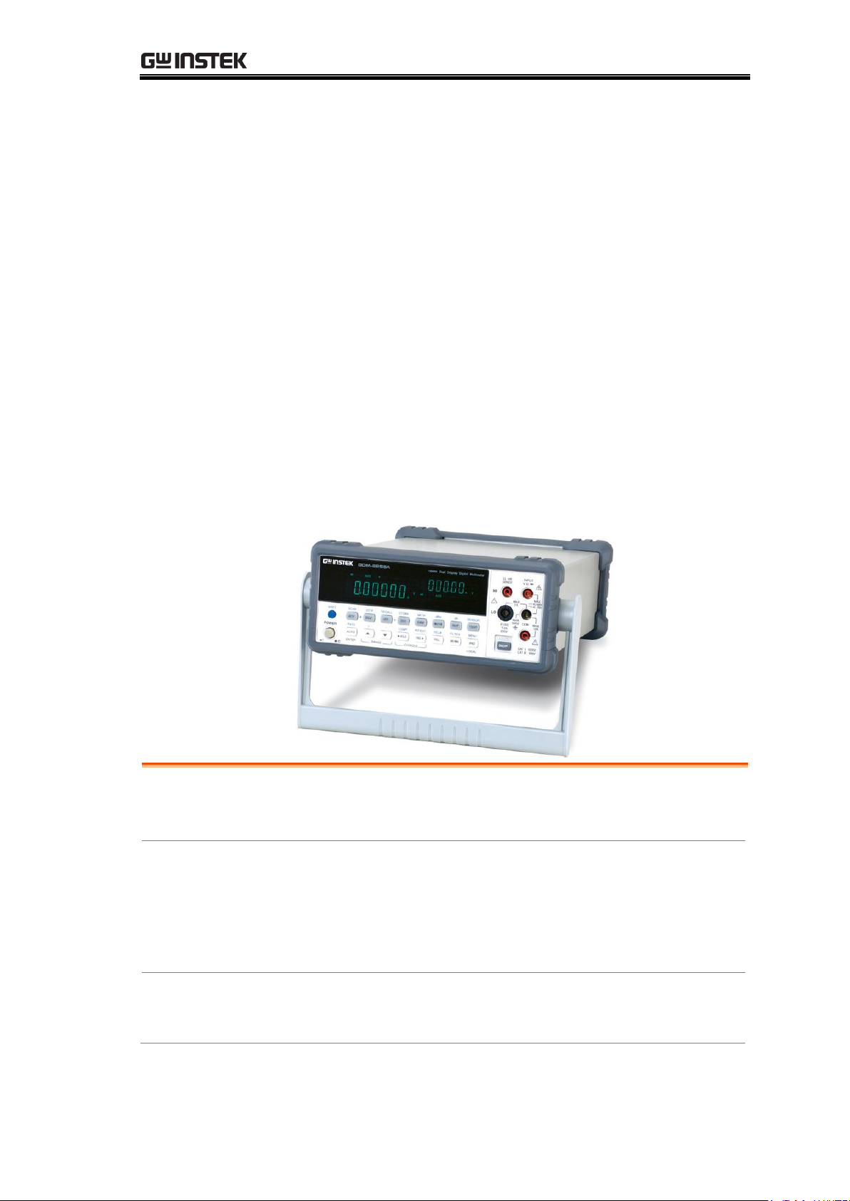
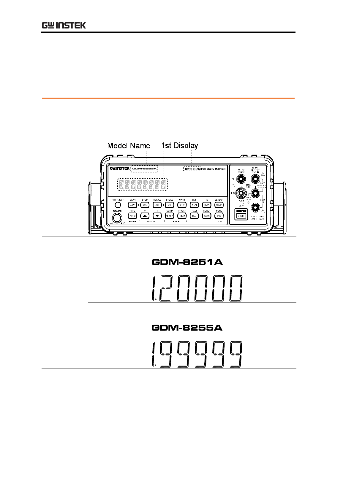
Appearance
Both two models are identical except for the model name and
the meter count of the 1st display.
Models
GDM-8251A
1st display meter: 120,000 counts
GDM-8255A
1st display meter: 199,999 counts
GDM-8200A Series Lineup
The GDM-8200A series consists of two models:
GDM-8251A and GDM-8255A.
10
Page 11

GETTING STARTED
Performance
High DCV accuracy: 0.012%
High current range: 10A
High Voltage range: 1000V
High ACV frequency response: 100kHz
Features
120000 meter count (GDM-8251A)
199999 meter count (GDM-8255A)
Multi functions: ACV, DCV, ACI, DCI, 2W/4W R, Hz,
Continuity, Diode test, MAX/MIN, REL, dBm,
HOLD, AutoHold, Compare.
Manual or Auto ranging
AC true RMS or AC + DC true RMS
Interface
Voltage/Resistance/Diode/Temperature input
Current input
4W sense input
USB device/RS232 for remote control
9-pin digital I/O
16 channel scanner x2 (optional)
Optional Items
16 channel scanner x 2
GDM-8200A Series Characteristics
The GDM-8200A series are portable, dual-display digital
multimeters suitable for wide range of applications, such
as production testing, research, and field verification.
11
Page 12
GDM-8200A Series User Manual
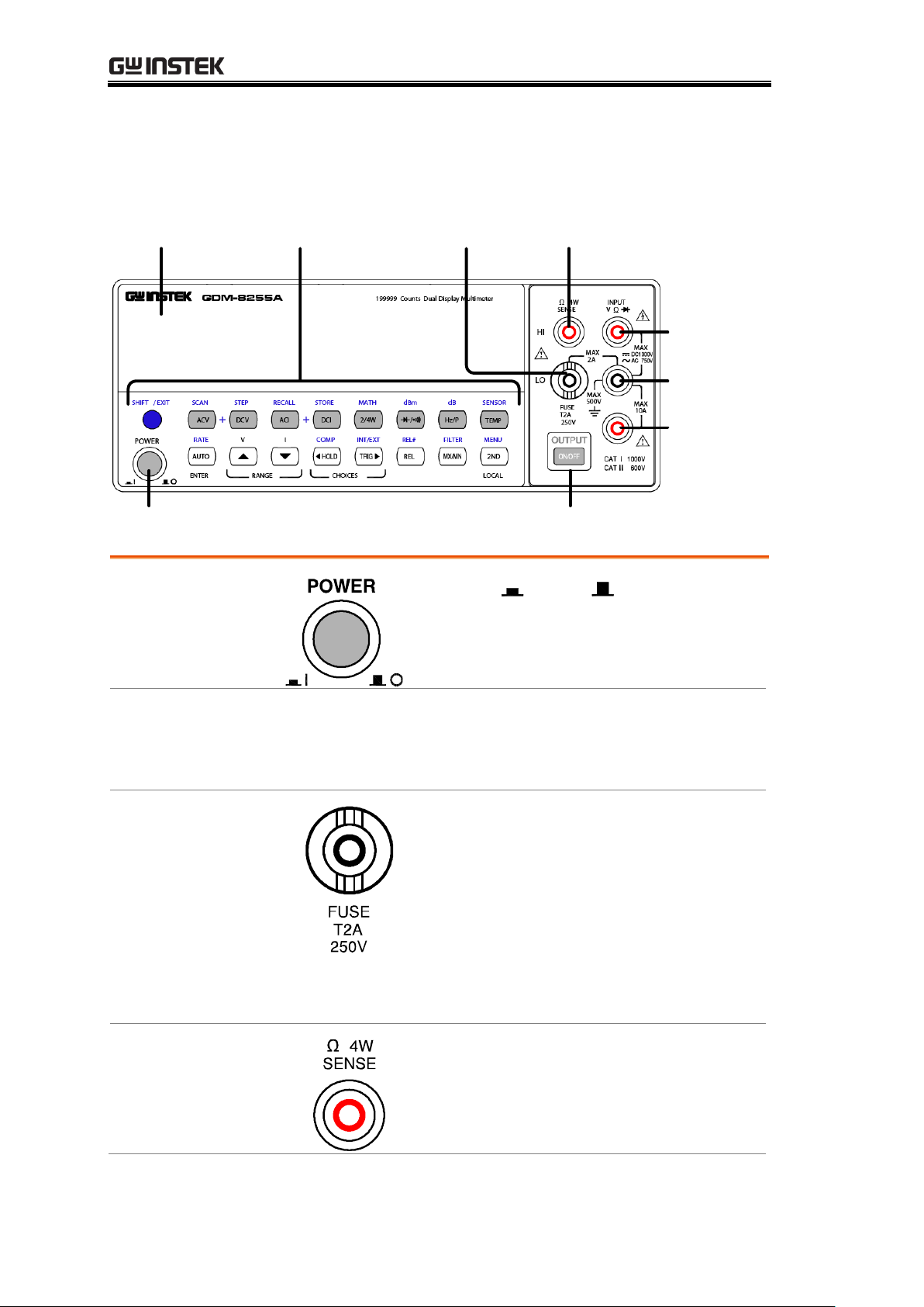
Measurement
keys
Main
Terminal
4W Ohm
Terminal
Fuse
Power Switch
Main
Display
DCI/ACI
Terminal
Output On/
Off key
COM
Terminal
Power Switch
Turns On or Off the main power.
For power up sequence, see page20.
Main Display
Shows measurement results and parameters.
For display configuration details, see page64 (light
setting).
Input fuse / 4W
Ω sense LO
terminal
As a fuse, protects the instrument from
over-current. Rating: T2A, 250V.
For fuse replacement procedure, see
page113.
As a sense terminal, accepts 4W Ω
measurement LO connection. Also
accepts current input less than 2A. For
details, see page30.
4W Ω Sense HI
Terminal
Accepts HI sense line in 4W resistance
measurement. For details, see page30.
Front Panel Overview
12
Page 13
GETTING STARTED
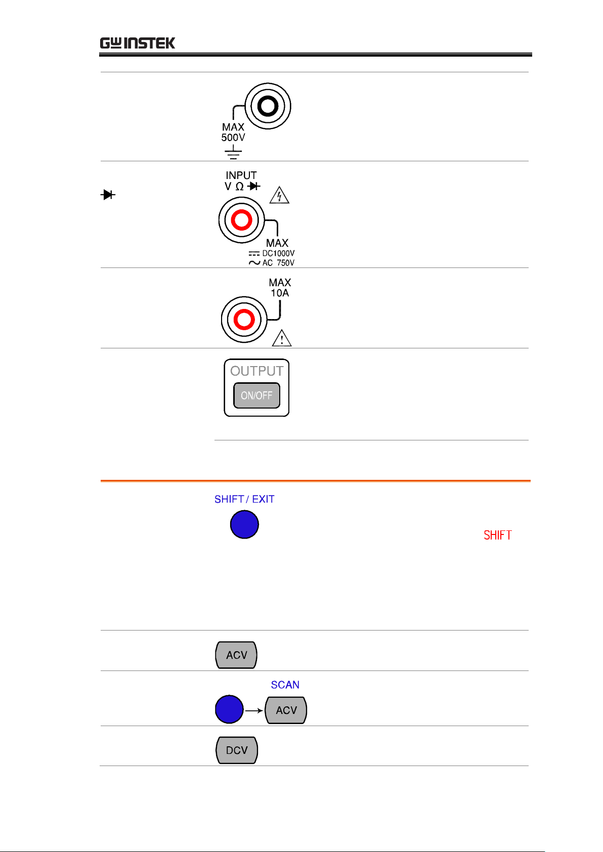
COM Terminal
Accepts ground (COM) line in all
measurements except the sense line in
4W Resistance (page30).
Voltage/ 2W Ω /
(Diode)
Terminal
Accepts input in all measurements
except for DC/AC Current and 4W
Resistance sense line.
Current Terminal
Accepts DC/AC Current input.
For DCI/ACI details, see page28.
Output On/Off
key
Turns the display on or off. When the
display is turned off, all panel keys
except the Output On/Off key become
disabled. The Output On/Off key is On
by default.
SHIFT/EXIT
As the Shift key, selects the second
functionality assigned to each front
panel key. When pressed, the
indicator appears in the display.
As the Exit key, gets out of the
parameter configuration mode and
goes back to the measurement result
display mode.
ACV
Measures AC Voltage (page24).
SHIFT → ACV
(SCAN)
Starts the optional scan measurement
(page80).
DCV
Measures DC Voltage (page24).
Measurement keys (Upper row)
13
Page 14
GDM-8200A Series User Manual
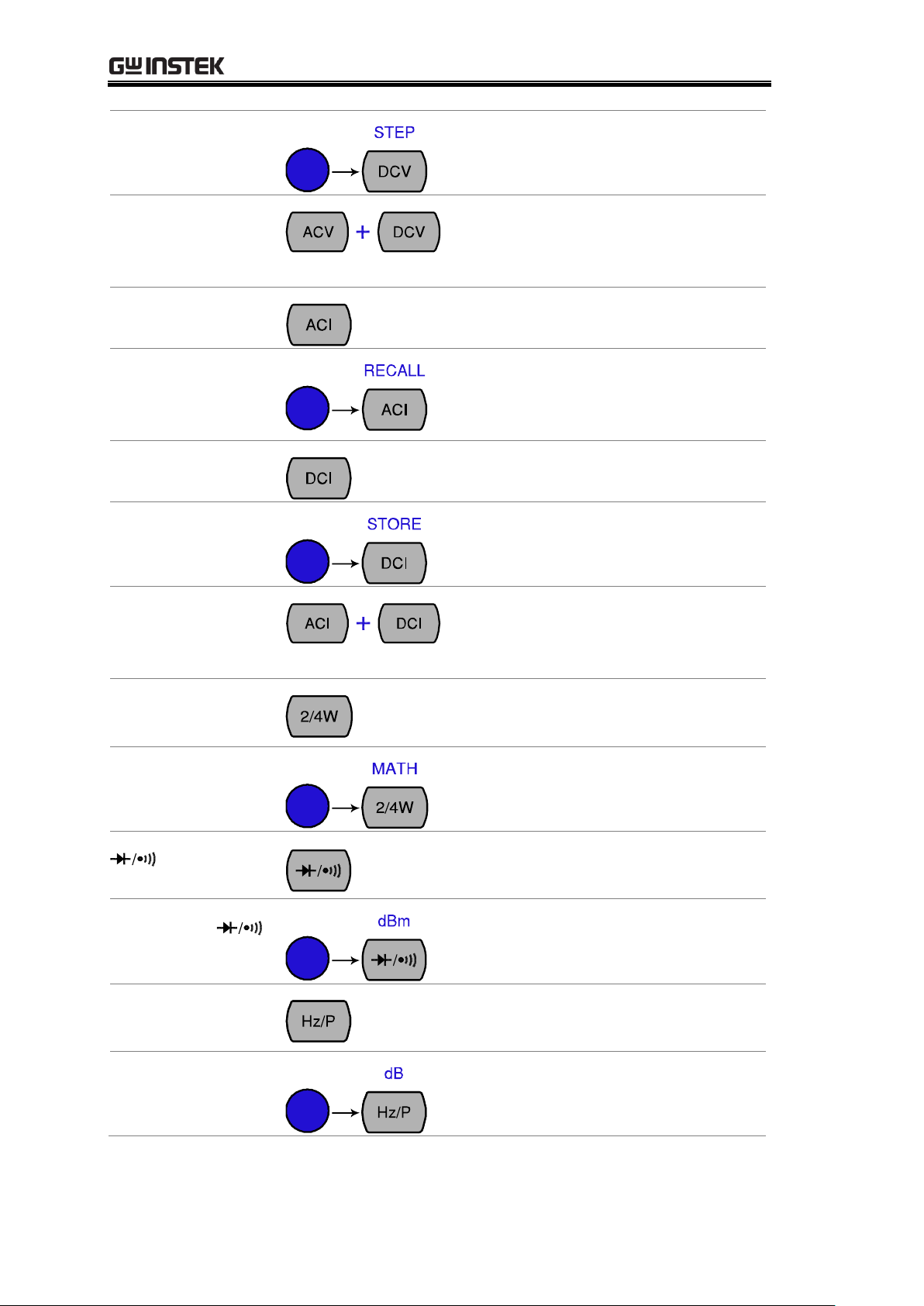
SHIFT → DCV
(STEP)
Starts the step measurement (page80)
using the optional scanner.
ACV + DCV
When the ACV key and the DCV key
are pressed together, they measure
AC+DC Voltage (page24).
ACI
Measures AC Current (page28).
SHIFT → ACI
(RECALL)
Recalls a normal measurement result
(page68) or a scan measurement
result (page88).
DCI
Measures DC Current (page28).
SHIFT → DCI
(STORE)
Stores a measurement result
(page67).
ACI + DCI
When the ACI key and the DCI key
are pressed together, they measure
AC+DC Current (page28).
2/4W
(Resistance)
Measures 2-wire or 4-wire Resistance
(page30).
SHIFT → 2/4W
(MATH)
Enters the Math measurement mode
(page52).
(Diode/
Continuity)
Tests Diode (page32) or Continuity
(page33).
SHIFT →
(dBm)
Measures dBm (page43).
Hz/P (Frequency/
Period)
Measures Frequency or Period
(page36).
SHIFT + Hz/P
(dB)
Measures dB (page44).
14
Page 15
GETTING STARTED
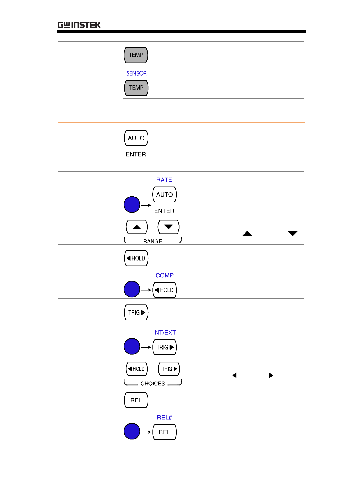
(Temperature)
Measures Temperature (page37).
SHIFT + TEMP
(SENSOR)
Selects the type of thermocouple
used in the Temperature
measurement (page38).
AUTO/ENTER
As the AUTO key, selects the
measurement range automatically.
As the ENTER key, confirms the
entered value.
SHIFT → AUTO
(RATE)
Selects the measurement update rate:
Slow, Medium, or Fast (page22).
Up/Down
Selects the parameter in various
occasions: higher ( ) or lower ( ).
HOLD
Activates the Hold function (page48).
SHIFT → HOLD
(COMPare)
Activates the Compare measurement
(page49).
TRIG (Trigger)
Triggers sample acquisition manually
(page59).
SHIFT → TRIG
(Int/Ext Trigger)
Selects the Internal or the External
trigger source (page59).
Left/Right
Selects the parameter in various
occasions: left ( ) or right ( ).
REL
Measures the Relative value (page46).
SHIFT → REL
(RELative base)
Manually sets the reference value for
the Relative value measurement
(page46).
Measurement keys (Lower row)
15
Page 16
GDM-8200A Series User Manual
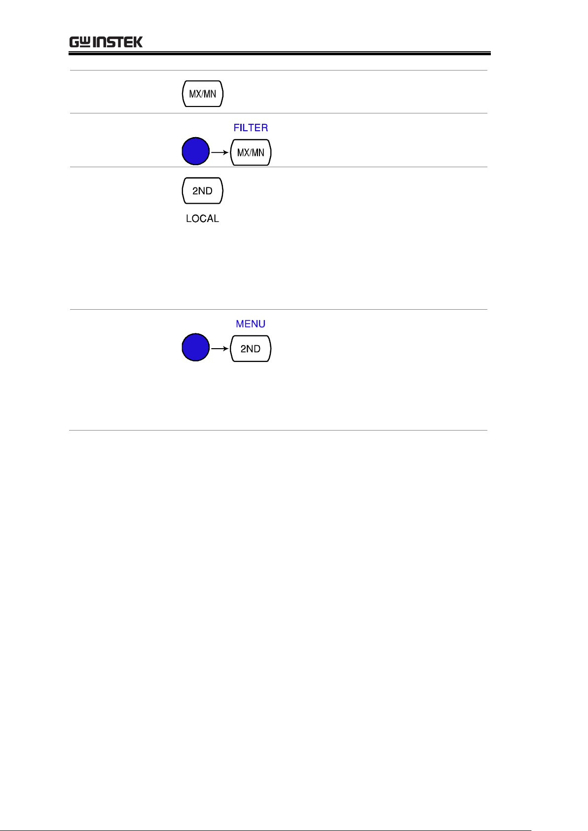
MX/MN
(MAX/ MIN)
Measures the Maximum or the
Minimum value (page45).
SHIFT →
MX/MN (FILTER)
Selects the digital filter type for the
signal sampling (page62).
2ND (Display) /
LOCAL
As the 2nd key, selects the
measurement item on the 2nd display
(page55). Pressing and holding for
more than 1 second turns off the 2nd
display.
As the Local key, releases the remote
control and goes back to the local
panel operation (page96).
SHIFT → 2ND
(Menu)
Enters the configuration mode.
Configures or displays the following
items: Display (page57), Beep
(page35), Continuity threshold
(page34), Scanner (page80), Digital
I/O (page90), and System
information (page110).
16
Page 17
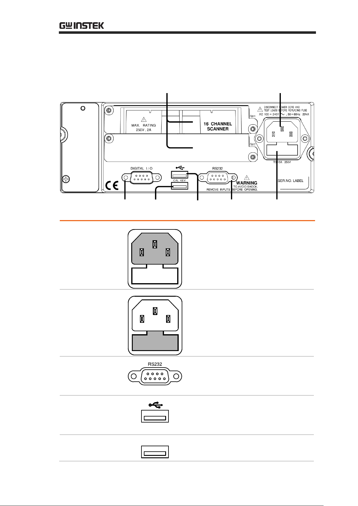
GETTING STARTED
RS-232C
Port
Optional Item
Slot x2
Power Cord
Socket
Fuse
T3.15A/250V
CAL Key
Port
Digital I/O
Port
USB Device
Port
Power Cord
Socket
Accepts the power cord. AC
100–240V, 50–60Hz.
For power on sequence, see page20.
Fuse Socket
Holds the main fuse: T3.15A 250V,
20VA.
For fuse replacement details, see
page112.
RS-232C port
Accepts an RS-232C cable for remote
control; DB-9 male connector.
For remote control details, see page97.
USB device port
Accepts a USB device cable for remote
control; Type A, female connector.
For remote control details, see page96.
CAL key port
CAL KEY
Reserved for internal uses as in
firmware update and calibration.
Rear Panel Overview
17
Page 18
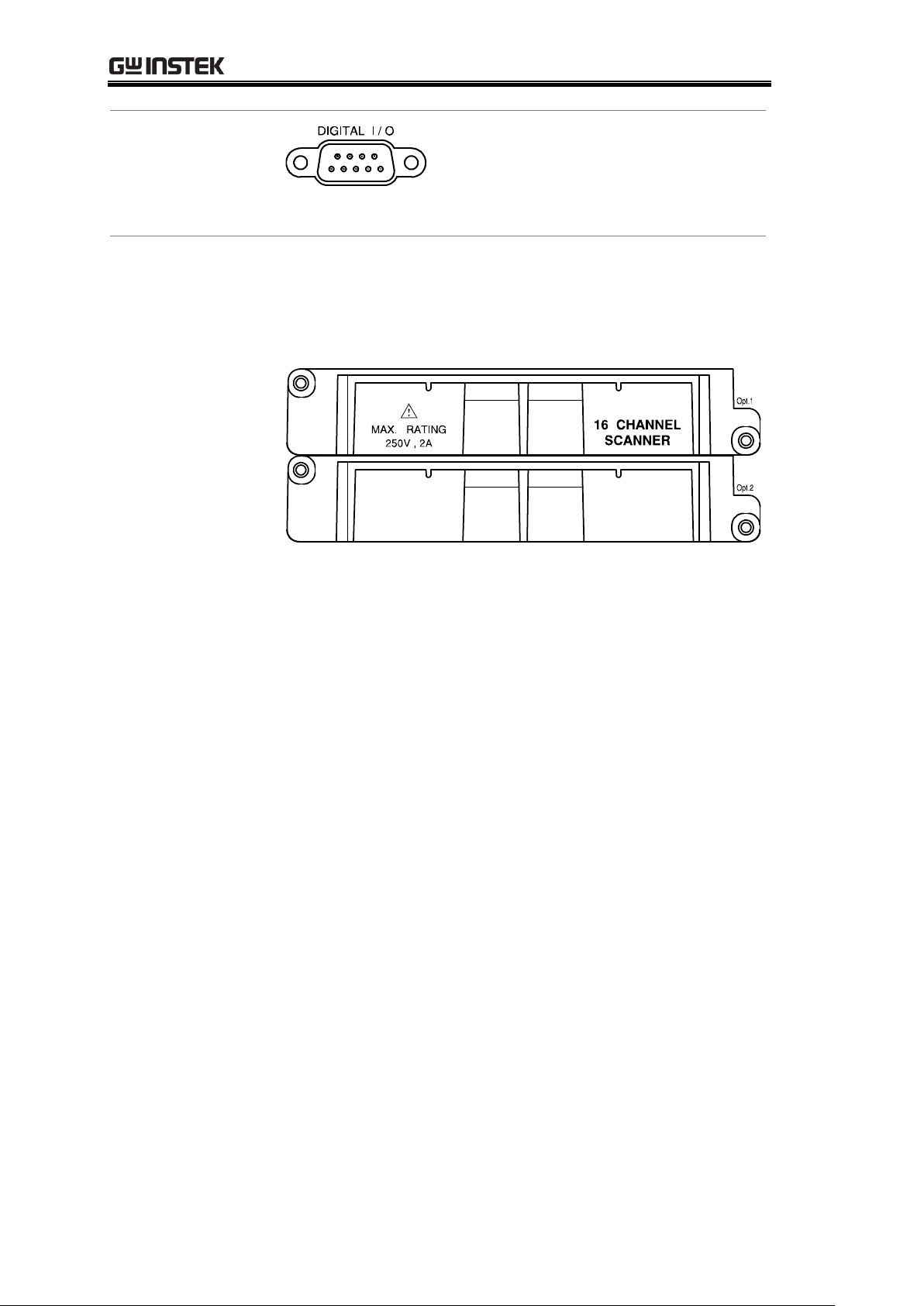
GDM-8200A Series User Manual
Digital I/O port
Accepts a digital I/O cable for the
Hi/Lo limit test; DB-9 pin, female
connector.
For digital I/O details, see page91.
Optional slot x2
Accepts up to two optional scanner modules. 16
channels are available per scanner. When two modules
are used, maximum 32 channels are available.
For scanner details, see page71.
18
Page 19
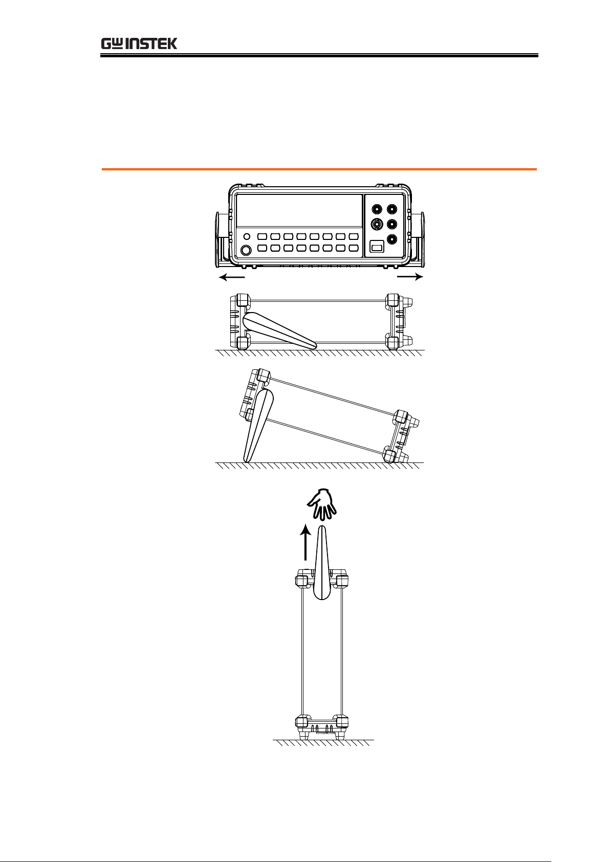
Set Up
Tilt stand steps
Pull out the
handle sideways
and rotate it.
Place the unit
horizontally,
Or in the tilt
stand position.
Place the handle
vertically for hand
carry.
Tilt Stand
GETTING STARTED
19
Page 20
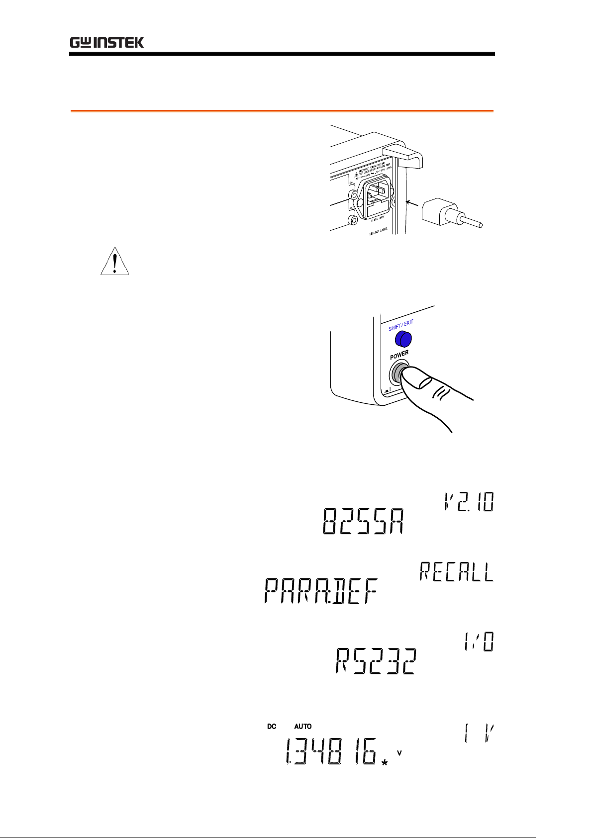
Power Up
Power up steps
1. Connect the power
cord to the AC
Voltage input.
Note
Make sure the ground connector of the power cord
is connected to a safety ground. This will affect the
measurement accuracy.
2. Push to turn On the
main power switch on
the front panel.
3. The display shows the model name and the version
for a few seconds.
Example: GDM-8255A, V2.10
4. Followed by the default measurement settings.
5. And the interface I/O settings.
6. Then the default setting appears.
Example: DCV, Auto, 1V range
GDM-8200A Series User Manual
20
Page 21
BASIC MEASUREMENT
Overview
Basic Measurement Overview ................................ 22
Common attribute: refresh rate .............................. 22
Common attribute: reading indicator ..................... 23
Common attribute: manual/automatic triggering .. 23
Voltage
AC/DC/AC+DC Voltage Measurement .................... 24
Select Voltage range ............................................... 25
Voltage conversion table ........................................ 26
Crest factor table .................................................... 27
Current
AC/DC/AC+DC Current Measurement ................... 28
Select Current range ............................................... 29
Resistance
2W/4W Resistance Measurement ........................... 30
Select Resistance range .......................................... 31
Diode
Diode Test .............................................................. 32
Continuity
Continuity Test ....................................................... 33
Set continuity threshold ......................................... 34
Select beeper setting .............................................. 35
Frequency/
Period
Frequency/Period Measurement ............................ 36
Temperature
Temperature Measurement .................................... 37
Select thermocouple type ....................................... 38
Set reference junction temperature ........................ 39
BASIC MEASUREMENT
21
Page 22
GDM-8200A Series User Manual
Background
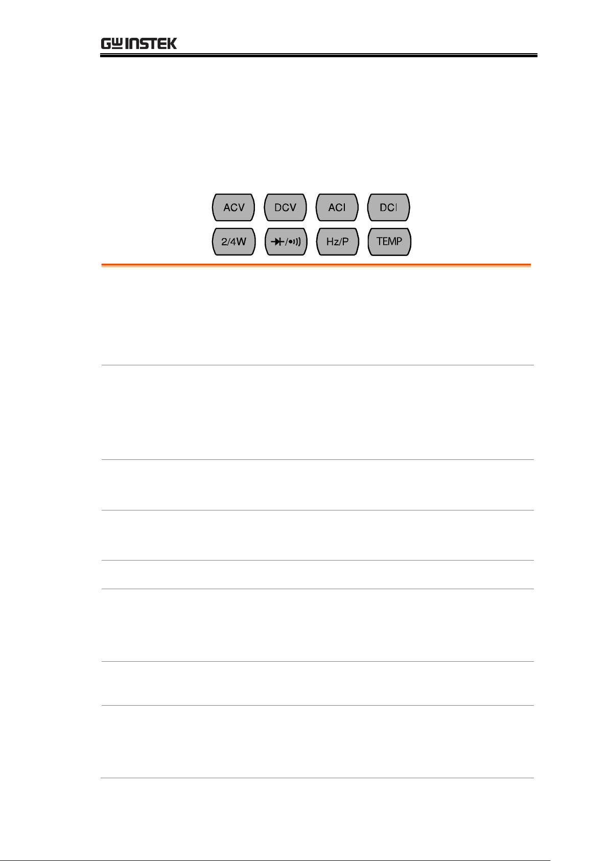
Basic measurement refers to the eight types of
measurements assigned to the upper row keys on the front
panel.
Measurement
type
ACV
AC Voltage
DCV
DC Voltage
ACV+DCV
AC+DC Voltage
ACI
AC Current
DCI
DC Current
ACI+DCI
AC+DC Current
2/4W
2-wire and 4-wire Resistance
Diode/Continuity
Hz/P
Frequency/Period
TEMP
Celsius/Fahrenheit Temperature
Advanced
measurement
Advanced measurement (page40) mainly refers to the
operation using the result obtained from one or more of
the basic measurement.
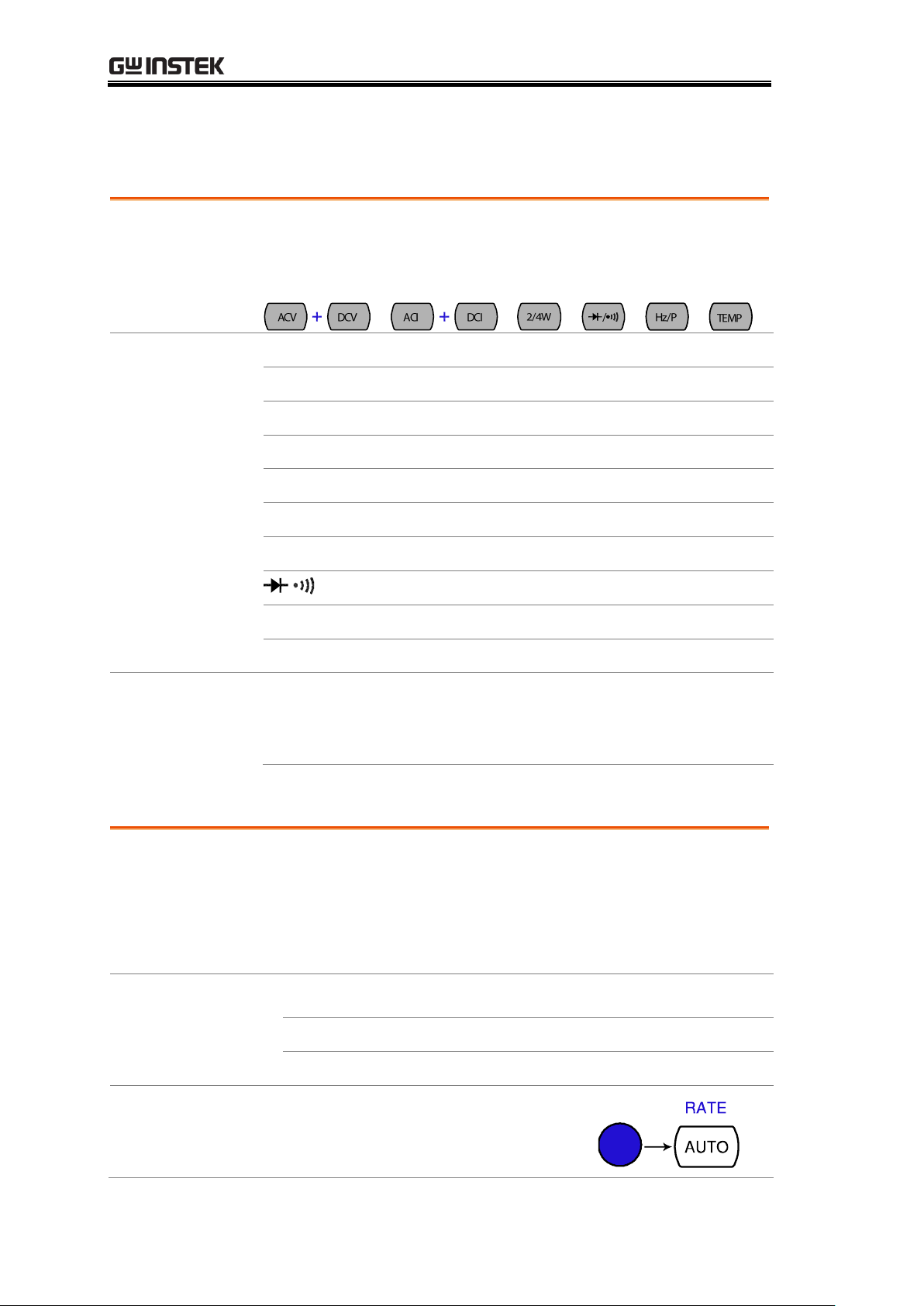
Background
Refresh rate defines how frequently the GDM-8200A
series captures and updates the measurement data. Faster
refresh rate yields lower accuracy and resolution. Slower
refresh rate yields higher accuracy and resolution.
Consider these trade-offs when selecting the refresh rate.
Range
S
5 ½ digits
M 4 ½ digits
F 3 ½ digits
Selection step
1. Press the Shift key followed by
the AUTO (RATE) key. The
refresh rate switches to the next.
Basic Measurement Overview
Common attribute: refresh rate
22
Page 23
BASIC MEASUREMENT
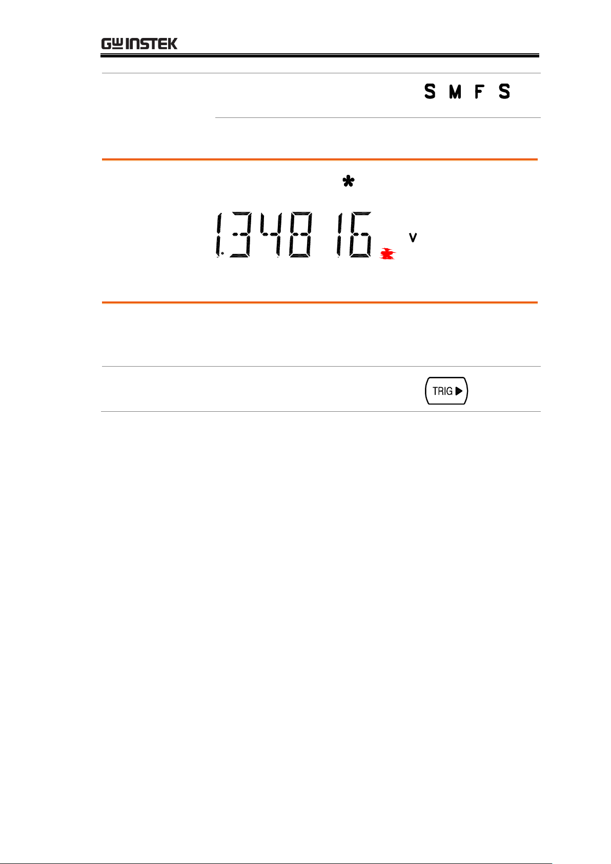
2. The refresh rate indicator shows
the current status.
→ → →
Background
The reading indicator next to the 1st display flashes
according to the refresh rate setting.
Automatic
triggering
(default)
The GDM-8200A series triggers according to the refresh
rate. See the previous page for refresh rate setting details.
Manual
triggering
Press the TRIG key to trigger
measurement manually.
Common attribute: reading indicator
Common attribute: manual/automatic triggering
23
Page 24
GDM-8200A Series User Manual
Voltage type
AC
0 ~ 750V
DC
0 ~ 1000V
AC+DC
0 ~ 1000V
AC2+DC
2
*AC+DC=
(AC = true RMS)
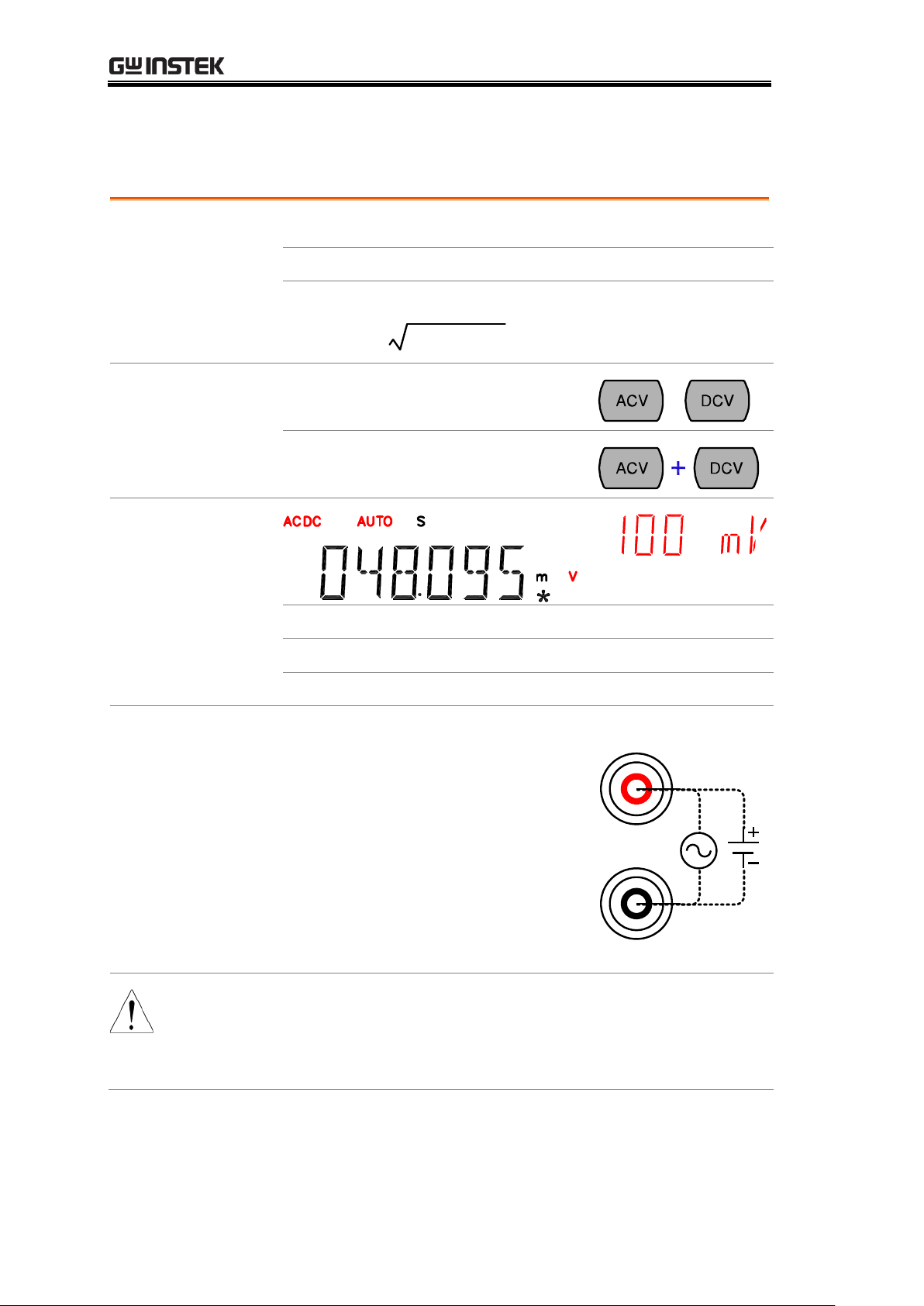
1. Activate ACV/
DCV
Press the ACV (AC Voltage) key or
DCV (DC Voltage) key.
or
For AC+DC Voltage, press the ACV
key and the DCV key together.
2. ACV/DCV
mode display
appears
AC(DC) + V
Indicates AC, DC, AC+DC Voltage
AUTO
Indicates Automatic range selection
100mV
2nd display shows the Voltage range
3. Connect the
test lead and
measure
Connect the test lead between the V
and the COM port. The display
updates the reading.
V
COM
Note
When measuring in1000V (maximum) range immediately
followed by 100mV (minimum) range, an error might
occur due to extreme range switching. In such case, take
at least one minute in between as an interval.
AC/DC/AC+DC Voltage Measurement
24
Page 25

BASIC MEASUREMENT
Auto range
To turn the automatic range selection
On/Off, press the AUTO key.
Manual range
Press the Up or the Down key to select
the range. AUTO indicator turns Off
automatically. If the appropriate range
is unknown, select the highest range.
Selection list
Range
Resolution / Full scale @ slow rate
Resolution
Full scale
(GDM-8251A)
Full scale
(GDM-8255A)
100mV
1µV
120.000mV
199.999mV
1V
10µV
1.20000V
1.99999V
10V
100µV
12.0000V
19.9999V
100V
1mV
120.000V
199.999V
750V (AC)
10mV
750.00V
750.00V
1000V
(DC, AC+DC)
10mV
1000.0V
1000.0V
Note
For more detailed parameters, see the specifications at
page114.
Select Voltage range
25
Page 26
GDM-8200A Series User Manual
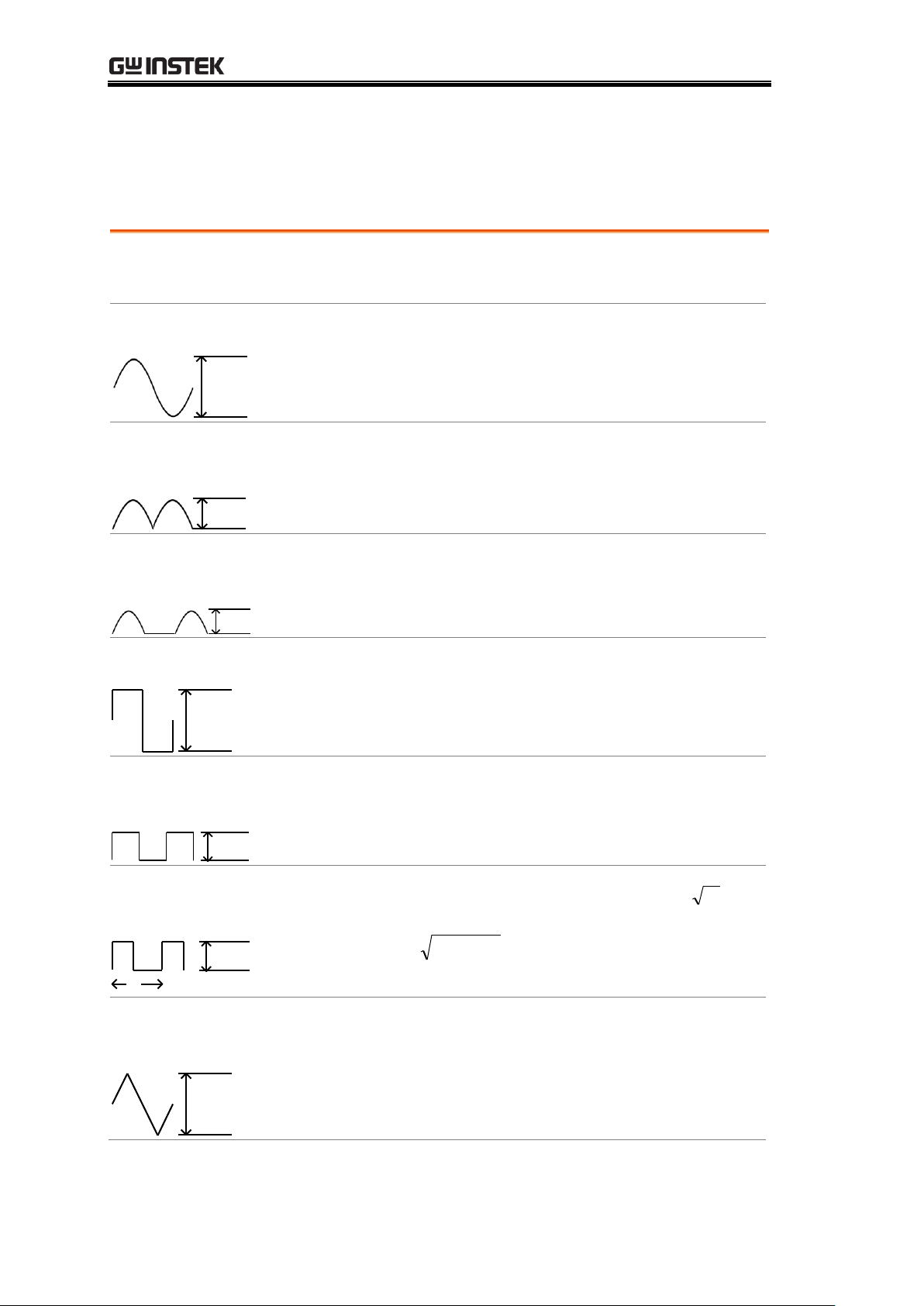
Waveform
Peak to Peak
AC
(True RMS)
DC
AC + DC
(True RMS)
Sine
PK-PK
2.828
1.000
0.000
1.000
Rectified Sine
(full wave)
PK-PK
1.414
0.435
0.900
1.000
Rectified Sine
(half wave)
PK-PK
2.000
0.771
0.636
1.000
Square
PK-PK
2.000
1.000
0.000
1.000
Rectified
Square
PK-PK
1.414
0.707
0.707
1.000
Rectangular
Pulse
PK-PK
X
Y
2.000
2K
K=
)2
( DD
D=X/Y
2D
D=X/Y
2
D
D=X/Y
Triangle
Sawtooth
PK-PK
3.464
1.000
0.000
1.000
Voltage conversion table
This table shows the relationship between AC, DC, and AC+DC reading in
various waveforms.
26
Page 27
BASIC MEASUREMENT
Background
Crest factor is the ratio of the peak signal amplitude to the
RMS value of the signal. It determines the accuracy of AC
measurement.
If the crest factor is less than 3.0, voltage measurement will
not result in error due to dynamic range limitations at full
scale.
If the crest factor is more than 3.0, it usually indicates
abnormal waveform as seen from the below table.
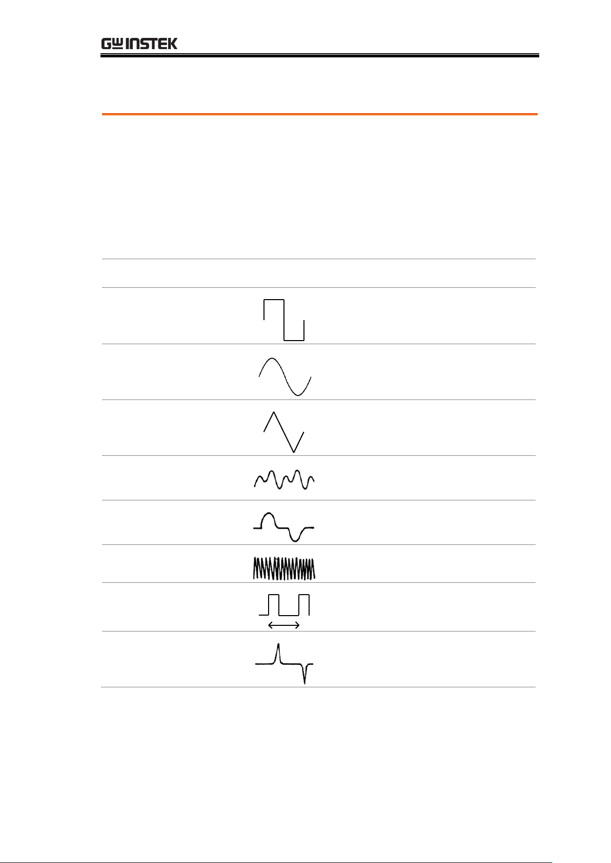
Waveform
Shape
Crest factor
Square wave 1.0
Sine wave 1.414
Triangle
sawtooth
1.732
Mixed
frequencies
1.414 ~ 2.0
SCR output
100% ~ 10%
1.414 ~ 3.0
White noise
3.0 ~ 4.0
AC Coupled
pulse train
3.0
Spike
>9.0
Crest factor table
27
Page 28
GDM-8200A Series User Manual
Current type
AC
0 ~ 10A
DC
0 ~ 10A
AC+DC
0 ~ 10A
AC2+DC
2
*AC+DC=
(AC = true RMS)
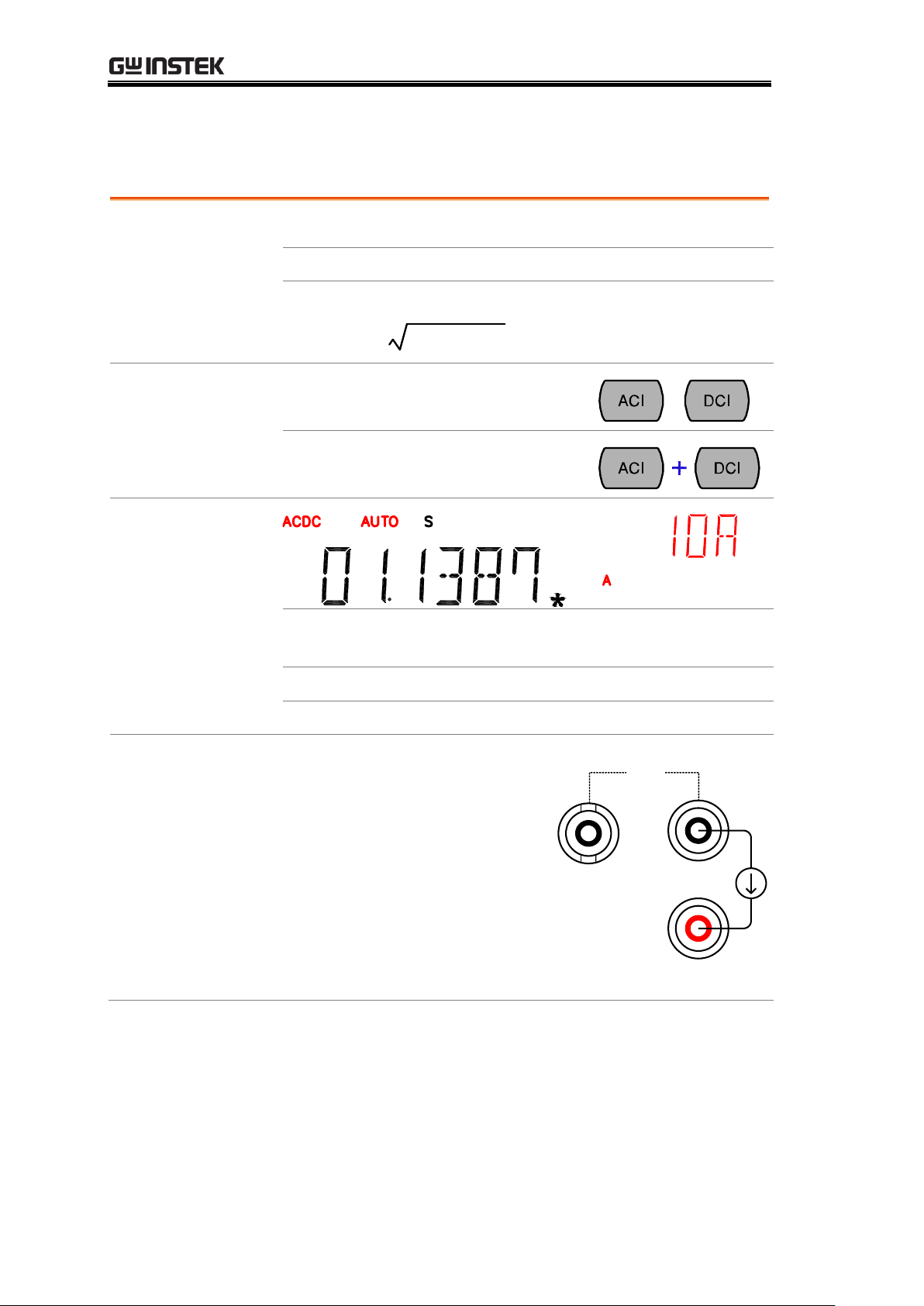
1. Activate ACI/
DCI
Press the ACI (AC Current) key or
the DCI (DC Current) key.
or
For AC+DC Current, press the ACI
key and the DCI key together.
2. ACI/DCI mode
display appears
AC(DC) + A
Indicates AC, DC, AC+DC Current
(Note: AC = true RMS)
AUTO
Indicates Automatic range selection
10A
2nd display shows the Current range
3. Connect the
test lead and
measure
Connect the test lead
between the A and COM
port or LO to COM port,
depending on the current.
For current ≤ 2A* use the
LO port; For current up to
10A use the A port. The
display updates the reading.
*2A (GDM-8255A, 1.2A
GDM-8251A)
A
COM
LO
MAX
2A
AC/DC/AC+DC Current Measurement
28
Page 29
BASIC MEASUREMENT
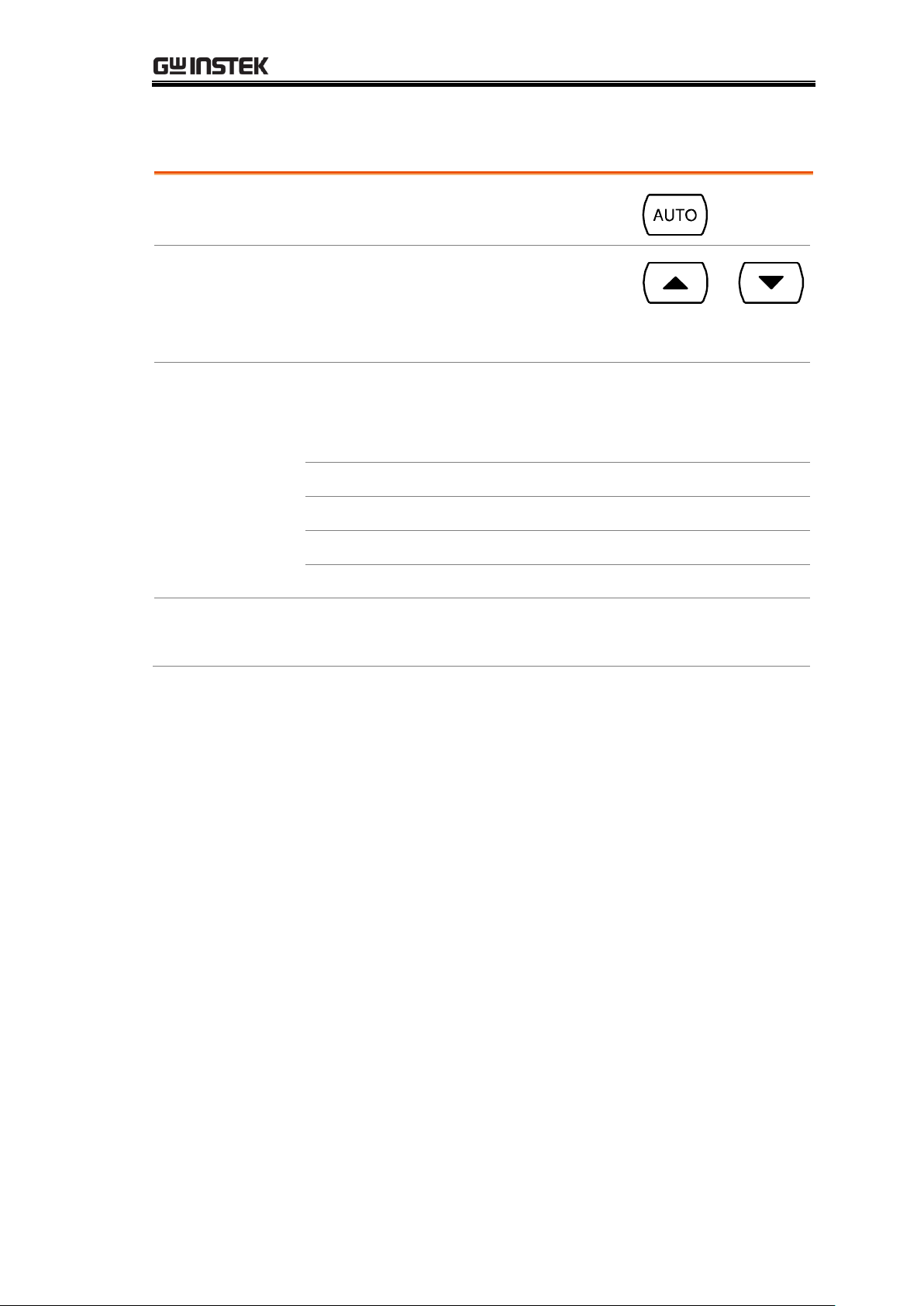
Auto range
To turn the automatic range selection
On/Off, press the AUTO key.
Manual range
Press the Up or the Down key to select
the range. AUTO indicator turns Off
automatically. If the appropriate range
is unknown, select the highest range.
Selection list
Range
Resolution / Full scale @ slow rate
Resolution
Full scale
(GDM-8251A)
Full scale
(GDM-8255A)
10mA
0.1µA
12.0000mA
19.9999mA
100mA
1µA
120.000mA
199.999mA
1A
100µA
1.2000A
1.9999A
10A
100µA
10.0000A
10.0000A
Note
*10A range is not available for AC+DC Current.
For more detailed range, see the specifications at page116.
Select Current range
29
Page 30
GDM-8200A Series User Manual
Measurement
type
2-wire
Uses the standard V-COM ports.
Recommended for measuring resistances
larger than 1kΩ.
4-wire
Compensates the test lead effect using the
4W compensation ports, in addition to the
standard V-COM ports.
Recommended for measuring sensitive
resistances smaller than 1kΩ.
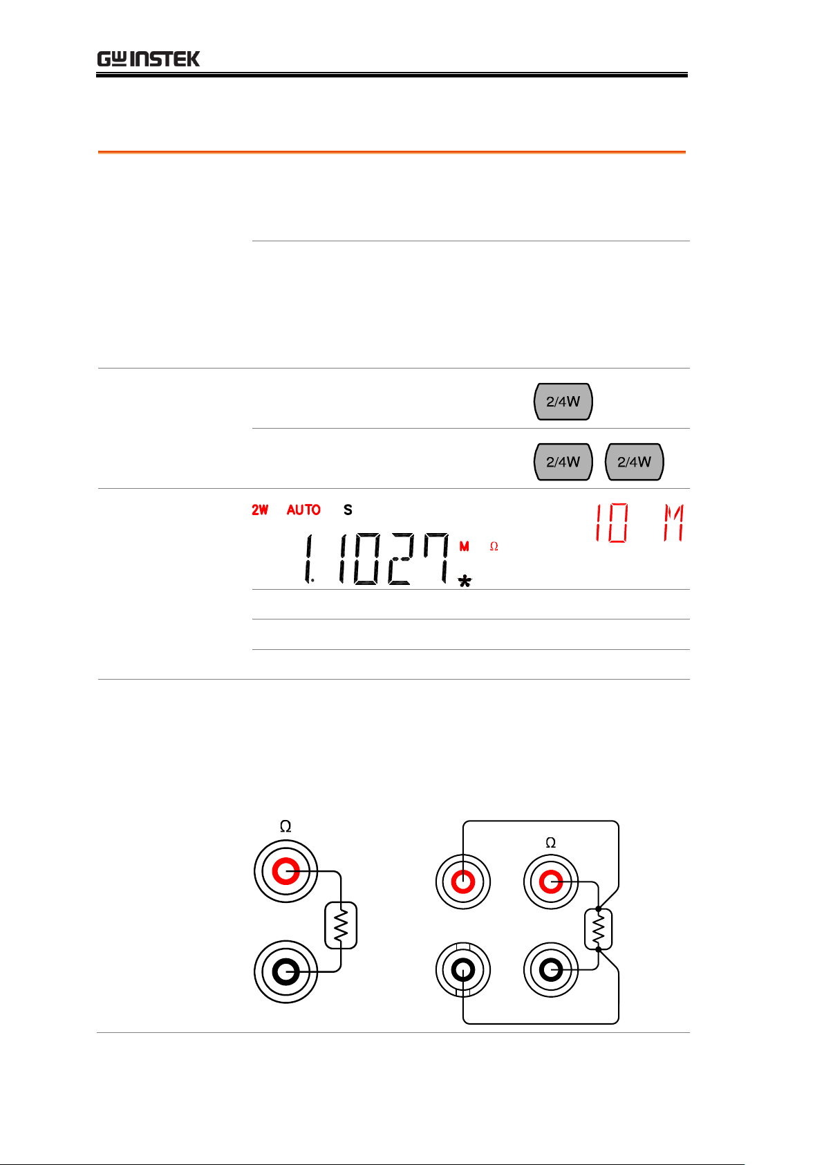
1. Activate
resistance
measurement
For 2-wire resistance measurement,
press the 2W/4W key once.
For 4-wire resistance measurement,
press the 2W/4W key twice.
2. 2W resistance
mode display
appears
2W(4W) + Ω
Indicates 2W(4W) Resistance mode
AUTO
Indicates Automatic range selection
10M
2nd display shows the Resistance range
3. Connect the
test lead and
measure
Connect the test lead. For 2-wire resistance, use the Ω (V)
and the COM port. For 4-wire resistance, use the Ω (V)
and the COM port, plus the 4W sense, and LO port for
sensing. The display updates the reading.
2W connection
COM
4W connection
COM
4W
SENSE
LO
2W/4W Resistance Measurement
30
Page 31

BASIC MEASUREMENT
Auto range
To turn the automatic range selection
On/Off, press the AUTO key.
Manual range
Press the Up or the Down key to select
the range. AUTO indicator turns Off
automatically. If the range is unknown,
select the highest range.
Selection list
Range
Full scale @ slow rate
GDM-8251A
GDM-8255A
100Ω
120.000Ω
199.999Ω
1kΩ
1.20000kΩ
1.99999kΩ
10kΩ
12.0000kΩ
19.9999kΩ
100kΩ
120.000kΩ
199.999kΩ
1MΩ
1.20000MΩ
1.99999MΩ
10MΩ
12.0000MΩ
19.9999MΩ
100MΩ
120.000MΩ
199.999MΩ
Note
For more detailed range, see the specifications at page118.
Select Resistance range
31
Page 32

GDM-8200A Series User Manual
Background
Diode test checks the forward bias characteristics of a
diode by running a constant forward bias current, approx.
0.5mA, through the DUT.
1. Activate diode
test
Press the key once.
2. Diode mode
display appears
+ V
Indicates Diode test
DIODE
2nd display shows the title
3. Connect the
test lead and
measure
Connect the test lead between the
and COM port; Anode-V,
Cathode-COM. The display updates
the reading.
COM
Diode Test
32
Page 33

BASIC MEASUREMENT
Background
Continuity test checks that the resistance in the DUT is
low enough to be considered continuous (of conductive
nature).
1. Activate
continuity test
Press the key twice.
2. Continuity
mode display
appears
+ Ω
Indicates Continuity test
CONT
2nd display shows the title
3. Connect the
test lead and
measure
Connect the test lead between the Ω
and the COM port. The display
updates the reading.
COM
Continuity Test
33
Page 34

GDM-8200A Series User Manual
Background
Continuity threshold defines the maximum resistance
allowed in the DUT when testing the continuity.
Threshold Range
0 ~ 1000Ω, 1Ω resolution, 10Ω default
1. Activate
threshold setting
1. Press the Shift key, the 2ND
key,
the Right key. The measurement
menu appears.
2. Press the Down key, the Right
key, the Enter key. The
continuity threshold setting
appears.
2. Edit threshold
1. Move the cursor (the flashing
digit) using the Left/Right key.
2. Change the value using the
Up/Down key.
Range:
1 ~ 1000Ω, 1Ω resolution, default 10Ω
3. Go back to the
default display
Press the Enter key to confirm the
edited threshold. Press the Exit key
to go back to the default display.
Set continuity threshold
34
Page 35

BASIC MEASUREMENT
Background
Beeper setting defines how the GDM-8200A series
notifies the continuity test result to the user.
Beeper
parameter
Pass
Beeps when the test result is pass
Fail
Beeps when the test result is fail
Off
Beep function is turned Off
1. Activate
beeper setting
menu
1. Press the Shift key followed by
the 2nd (Menu) key. The system
menu appears.
2. Press the Down key. The beep
menu appears.
3. Press the Down key. The beep
setting appears.
2. Select the
beep setting
To change the setting, press the
Up/Down key.
Beeper type:
Pass (beep when pass), Fail (beep when
fail, default), Off (beep off)
3. Go back to the
default display
Press the Enter key to confirm.
Press the Exit key to go back to the
default display.
Select beeper setting
35
Page 36

GDM-8200A Series User Manual
1. Activate
frequency/period
measurement
To measure Frequency, press the
Hz/P key once.
To measure Period, press the Hz/P
key twice.
2. Frequency
(Period) mode
display appears
Hz (S)
Indicates Frequency (period) measurement
FREQ
(PERIOD)
2nd display shows the title
3. Connect the
test lead and
measure
Connect the test lead between the V
and the COM port. The display
updates the reading.
V
COM
Frequency range
10Hz ~ 800kHz
Sensitivity
10Hz ~ 100kHz: >0.1V
100kHz ~ 600kHz: >1.0V
600kHz ~ 800kHz: >2.5V
Period Range
1.25µs ~ 0.1s
Sensitivity
1.25us ~ 1.666us: > 2.5V
1.666us ~ 10us: > 1.0V
10us ~ 0.1s: > 0.1V
AC Current
Sensitivity
Frequency
Input level
Sensitivity level
10Hz~10kHz
10mA/100mA
> 7mA rms
45Hz~10kHz
1A/10A
> 3mA rms
Frequency/Period Measurement
36
Page 37

BASIC MEASUREMENT
Background
The GDM-8200A series accepts thermocouple input and
calculates the temperature from the voltage fluctuation.
Thermocouple type and reference junction temperature
are also being considered.
1. Activate
temperature
measurement
For Celsius units (°C), press the
TEMP key once.
For Fahrenheit (°F) unit, press the
TEMP key twice.
2. Temperature
mode display
appears
°C (°F)
Indicates Temperature measurement
TYPE J
2nd display shows the thermocouple type
3. Connect the
test lead and
measure
Connect the thermocouple lead
between the V and the COM port.
The display updates the reading.
V
COM
Range
0 ~ +300°C
Temperature Measurement
37
Page 38

GDM-8200A Series User Manual
Background
The GDM-8200A series assumes that a certain type of
thermocouple, which reads voltage fluctuation induced
by temperature changes, is used to measure the
temperature.
Parameter
Type
Range
Resolution
K
0 ~ +300°C
0.01°C
T
0 ~ +300°C
0.01°C
J
0 ~ +300°C
0.01°C
1. Open sensor
selection menu
Press the Shift key, then the TEMP
(Sensor) key. The sensor selection
menu appears on the display.
2. Select sensor
type
Press the Right key to highlight the
thermocouple type. Press the
Up/Down key. The thermocouple
type switches to the next one.
3. Confirm and
go back to the
default display
Press the Enter key to confirm the
sensor type. The display will then
automatically switch to the reference
junction temperature setting. Please
refer to Page 39 for related
information. If you don’t need to set
the reference junction temperature,
just press the Exit key to go back to
the default display.
Set Reference
Junction Setting
Or
Cancel setting
the sensor type
Press the Exit key to abort setting
the sensor type and go back to the
default display.
(cancel)
Select thermocouple type
38
Page 39

BASIC MEASUREMENT
Background
When a thermocouple is connected to the GDM-8200A
series, the temperature difference between the thermocouple
lead and the GDM-8200A series input terminal should be
taken into account and be cancelled; otherwise an erroneous
temperature might be added.
Type
Range
Resolution
SIM (simulated)
0 ~ +50°C
0.01°C
The terminal temperature is manually defined by the user.
Default value: 23.00
1. Open
reference
junction
menu
Press the Shift key, the TEMP
(Sensor) key, then the Down key.
The reference junction selection
menu appears on the display.
2. Edit
reference
temperature
Use the Left/Right key to move
the cursor, and use the Up/Down
key to change the value.
Default: 23.00
Press the Enter key to confirm the
value, or the Exit key to cancel.
The display goes back to the
default state.
(confirm)
(cancel)
Set reference junction temperature
39
Page 40

GDM-8200A Series User Manual
Overview
Advanced Measurement Overview ......................... 41
Common attribute: refresh rate ............................. 41
Common attribute: reading indicator ..................... 42
Common attribute: manual/automatic triggering .. 42
dBm/dB
dBm/dB Measurement ........................................... 43
Measure dBm ......................................................... 43
Measure dB ............................................................ 44
Max/Min
Max/Min Measurement ......................................... 45
Relative
Relative Value Measurement .................................. 46
Hold
Hold Measurement ................................................ 48
Compare
Compare Measurement .......................................... 49
Math
Math Measurement ............................................... 52
Measure MX+B ...................................................... 52
Measure 1/X .......................................................... 54
Measure Percentage .............................................. 54
Dual Display
Dual Display Measurement .................................... 55
ADVANCED
MEASUREMENT
40
Page 41

ADVANCED MEASUREMENT
Background
Advanced measurement mainly refers to the type of
measurement which uses the result obtained by one of
the basic measurements: ACV, DCV, ACI, DCI, 2/4W,
Diode/Continuity, Frequency/Period, and Temperature.
Advanced
Measurement
Basic Measurement
AC/DCV
AC/DCI
2/4W
Hz/P
TEMP
dB
● — — — —
—
dBm
● — — — —
—
Max/Min
● ● ● ● ●
—
Relative
● ● ● ● ●
—
Hold
● ● ● ● ●
—
Compare
● ● ● ● ●
—
Math
● ● ● ● ●
—
Dual Measurement
● ● ● ● —
—
Background
Refresh rate defines how frequently the GDM-8200A
series captures and updates the measurement data. Faster
refresh rate yields lower accuracy and resolution. Slower
refresh rate yields higher accuracy and resolution.
Consider these trade-offs when selecting the refresh rate.
Range
S
5 ½ digits
M 4 ½ digits
F 3 ½ digits
Selection step
1. Press the Shift key followed by
the AUTO (RATE) key. The
refresh rate switches to the next.
Advanced Measurement Overview
Common attribute: refresh rate
41
Page 42

GDM-8200A Series User Manual
2. The refresh rate indicator shows
the current status.
→ → →
Background
The reading indicator next to the 1st display flashes
according to the refresh rate when the captured data is
updated on the display.
When no data is
captured
When there is no captured data, the reading indicator
flashes once every two seconds (slower than the normal
refresh rate), indicating the DMM is in the waiting mode.
Automatic
triggering
(default)
The GDM-8200A series triggers according to the refresh
rate. See the previous page for refresh rate setting details.
Manual
triggering
Press the TRIG key to trigger
measurement manually.
Common attribute: reading indicator
Common attribute: manual/automatic triggering
42
Page 43

ADVANCED MEASUREMENT
Applicable to
(NOT applicable to ACV+DCV)
Background
Using the ACV or DCV measurement result, the
GDM-8200A series calculates the dB or dBm value based
on a reference resistance value in the following way.
dBm
10 x log10 (1000 x Vreading2 / Rref)
dB
dBm – dBmref
Parameters
Vreading
Input Voltage, ACV or DCV
Vref
Reference voltage obtained by Rref/1mW
Rref
Reference resistance simulating an output
load
dBmref
Reference dBm value
Activate dBm
Press the Shift key followed by the
key. The 1st display shows dBm,
and the 2nd display shows the
reference resistance.
dBm result
appears
dBm
Indicates dBm measurement
600Ω
2nd display indicates the reference resistance
Select
reference
resistance
To change the reference resistance,
press the Up/Down key. The new
resistance appears in the 2nd display.
The following is the resistance list.
2 4 8
16
50
75
93 110
124
125
135
150
250
300
500
600
800
900
1000
1200
8000
dBm/dB Measurement
Measure dBm
43
Page 44

GDM-8200A Series User Manual
Deactivate dBm
measurement
To cancel the dBm measurement,
press the Shift key followed by the
key, or simply activate another
measurement.
Background
dB is defined as [dBm−dBmref]. When the dB
measurement is activated, the GDM-8200A series
calculates the dBm using the reading at the first moment
and stores it as dBmref.
Activate dB
Press the Shift key followed by the
Hz/P key. The 1st display shows dB,
and the 2nd display shows the
current Voltage reading.
dB result
appears
dB
Indicates dB measurement
113.729mV
Indicates the present Voltage reading
dBmref
Press the 2ND key to see the dBmref value.
Deactivate dB
measurement
To cancel the dBm measurement,
press the Shift key followed by the
Hz/P key, or simply activate another
measurement.
Measure dB
44
Page 45

ADVANCED MEASUREMENT
Applicable to
( )
+
( )
+
Background
Maximum and Minimum measurement stores the highest
(maximum) or lowest (minimum) reading and shows it on the 2nd
display.
1. Activate
Max/Min
For Max measurement, press the
MX/MN key once.
For Min measurement, press the
MX/MN key twice.
2. Max (Min)
result
appears
MIN (MAX)
Indicates Min (Max) measurement
0.11516
2nd display shows the Min (Max)
measurement result
Deactivate
Max/Min
measurement
To cancel the Max/Min measurement,
press the MX/MN key for 2 seconds, or
simply activate another measurement.
Max/Min Measurement
45
Page 46

GDM-8200A Series User Manual
Applicable to
( )
+
( )
+
Background
Relative measurement stores a value, typically the data at the
moment, as the reference. The following measurement is
shown as the delta between the reference.
1. Activate
Relative
measurement
Press the REL key. The
measurement reading at the
moment becomes the
reference value.
2. Relative
measurement
display
appears
REL
Indicates Relative value measurement
2nd
display
Shows the reference value
1st
display
Shows the delta between the current measurement
data and the reference value
Manually set
the reference
value
1. To set the reference
value manually, press
the Shift key followed
by the REL key. The
setting appears.
REL
Indicates Relative measurement
1st display
Shows the reference value
2nd
display
Indicates Relative value modification
Relative Value Measurement
46
Page 47

ADVANCED MEASUREMENT
2. Use the Left/Right key
to move the flashing
point (cursor), and use
the Up/Down key to
change the value.
3. Press the Enter key to
confirm the value, or
the Exit key to cancel.
The display switches to
measurement.
(confirm)
(cancel)
Deactivate
Relative
measurement
To cancel the Relative
measurement, press the
REL key again, or simply
activate another
measurement.
47
Page 48

GDM-8200A Series User Manual
Applicable to
( )
+
( )
+
Background
Hold measurement retains the current measurement data
and updates it only when the reading fluctuates more than
the threshold setting as the percentage of the retained data.
1. Activate
Hold
measurement
Press the HOLD key.
2. Hold
measurement
display
appears
HOLD
Indicates Hold measurement
2nd display
Shows the Hold threshold
1st display
The measurement data which is updated only
when it fluctuates more than the threshold
compared to the retained value.
3. Select hold
threshold
Select the hold threshold
using the Up/Down key. The
2nd display changes
accordingly.
Range
0 ~ 99%, 1% resolution
Deactivate
Hold
measurement
To cancel the Hold
measurement, press the Hold
key for 2 seconds, or simply
activate another
measurement.
Hold Measurement
48
Page 49

ADVANCED MEASUREMENT
Applicable to
( )
+
( )
+
Background
Compare measurement checks and updates if the
measurement data stays between the upper (high) and lower
(low) limit specified.
1. Activate
Compare
measurement
Press the Shift key, then the
HOLD (Comp) key.
2. High limit
setting
1st display
Shows the high limit value
2nd display
Indicates high limit setting
1. Use the Left/Right key to
move the cursor (flashing
point) between high/low
setting, digits, and
decimal point.
2. Change the parameter
using the Up/Down key.
3. Press the ENTER key to
confirm editing and move
to the low limit setting.
Compare Measurement
49
Page 50

GDM-8200A Series User Manual
3. Low limit
setting
1st display
Shows the low limit value
2nd display
Indicates low limit setting
1. Use the Left/Right key to move
the cursor (flashing point)
between high/low setting, digits,
and decimal point.
2. Change the parameter using the
Up/Down key.
3. Press the ENTER key to
confirm editing. The compare
measurement starts right away.
4. Compare
measurement
appears
COMP
Indicates Compare mode
2nd display
Shows the compare measurement result:
Pass, High, or Low.
50
Page 51

ADVANCED MEASUREMENT
5. Result
High
If the 2nd display
shows High, the result
is above the High
limit.
Digital I/O: FAIL Out (Pin 6) and HIGH
Limit FAIL Out (Pin 7) are activated.
Low
If the 2nd display
shows Low, the result
is below the Low limit.
Digital I/O: FAIL Out (Pin 6) and LOW
Limit FAIL Out (Pin 8) are activated.
Pass
If the 2nd display
shows Pass, the result
is staying between the
High and the Low
limit.
Digital I/O: PASS Out (Pin 5) is activated.
Digital I/O
The Compare
measurement result
comes out from the
rear panel Digital I/O
terminal. For the
terminal details, see
page90.
Deactivate
Compare
measurement
To cancel the Compare
measurement, press the Shift
key followed by the HOLD
(Comp) key, or simply activate
another measurement.
51
Page 52

GDM-8200A Series User Manual
Applicable to
( )
+
( )
+
Background
Math measurement runs three types of mathematical
operation, MX+B, 1/X, and percentage, based on the other
measurement results.
Math type
MX+B
Multiplies the reading (X) by the factor
(M) and adds/subtracts offset (B).
1/X
Divides the reading (X) by 1, which
provides the inverse number.
Percentage
Runs the following equation.
(ReadingX – Reference)
x 100%
Reference
1. Activate MX+B
Press the Shift key followed by the
2/4W (Math) key. The MX+B
setting appears.
2. Set the factor
(M)
1st display
Shows the factor (M)
2nd display
Indicates MX+B (The letter M flashes)
1. Use the Left/Right key to move
the cursor (flashing point)
between the factor, digits, and
decimal point.
Math Measurement
Measure MX+B
52
Page 53

ADVANCED MEASUREMENT
2. Change the parameter using the
Up/Down key.
3. Press the ENTER key to
confirm editing and move to
offset setting.
3. Set the offset
(B)
1st display
Shows the offset (B)
2nd display
Indicates MX+B (The letter B flashes)
1. Use the Left/Right key to move
the cursor (flashing point)
between the offset, digits, and
decimal point.
2. Change the parameter using the
Up/Down key.
3. Press the ENTER key to
confirm the editing. The MX+B
measurement result appears.
4. View MX+B
1st display
Shows the calculated result
2nd display
Indicates MX+B
MATH
Indicates Math operation
53
Page 54

GDM-8200A Series User Manual
1. Activate 1/X
Press the Shift key, the 2/4W (Math)
key, the Down key twice. The 1/X
setting appears.
2. View 1/X
Press the ENTER key to view the
1/X measurement result.
1st display
Shows the 1/X value
2nd display
Indicates 1/X
MATH
Indicates Math operation
1. Activate
Percentage
Press the Shift key, the 2/4W (Math)
key, the Up key. The Reference
setting appears. The Percentage is
calculated as:
[Reading−Reference]/Reference x
100%.
2. Set the
reference number
1st display
Shows the reference number
2nd display
Indicates Percentage setting
Measure 1/X
Measure Percentage
54
Page 55

ADVANCED MEASUREMENT
1. Use the Left/Right key to move
the cursor (flashing point)
between high/low setting, digits,
and decimal point.
2. Change the parameter using the
Up/Down key.
3. Press the ENTER key to
confirm editing.
3. View Percentage
1st display
Shows the calculated result
2nd display
Indicates the Percentage measurement
MATH
Indicates Math operation
Background
You can use the 2nd display to show another item, thus
viewing two different measurement results at once. The
following table shows the available options.
1st Display
2nd Display
ACV
DCV
ACI
DCI
Hz/P
ACV
● ● ● ● ●
DCV
● ● ● ● ●
ACV+DCV
— — — — —
ACI
● ● ● ● ●
DCI
● ● ● ● ●
ACI+DCI
— — — — —
Dual Display Measurement
55
Page 56

GDM-8200A Series User Manual
2W* (see Note)
● ● ● ● ●
Hz/P
● ● ● ● ●
TEMP
— — — — — — — — — —
Note
In the dual display mode, the resistance needs to be
larger than 1MΩ.
Some combination of dual display mode is possible but
may not be useful, and their accuracies are not
guaranteed.
2nd Measurement
item setting
Press the 2nd key, then the target
item (example: ACV). The display
updates the measurement result.
(example: ACI + ACV)
1st Display
Shows the primary measurement result
2nd Display
Shows the secondary measurement result
2ND
Indicates that dual measurement is active
Turn Off 2nd
Measurement
To turn Off the 2nd measurement,
press and hold the 2nd key for more
than 1 second.
56
Page 57

SYSTEM/DISPLAY CONFIGURATION
Refresh Rate
Refresh Rate Setting ............................................... 58
Trigger
Manual/Automatic triggering ................................. 59
Use external trigger ................................................ 59
Set trigger delay ..................................................... 60
Digital Filter
Overview ................................................................ 62
Filter setting ........................................................... 63
Display
Display Setting ....................................................... 64
Display on/off setting (+ key lock) ......................... 65
SYSTEM/DISPLAY
CONFIGURATION
57
Page 58

GDM-8200A Series User Manual
Background
Refresh rate defines how frequently the GDM-8200A
series captures and updates the measurement data. Faster
refresh rate yields lower accuracy and resolution. Slower
refresh rate yields higher accuracy and resolution.
Consider the trade-off when selecting the refresh rate.
Display/Range
S
5 ½ digits
M 4 ½ digits
F 3 ½ digits
Refresh rate
selection
Press the Shift key followed by the
AUTO key. The refresh rate
indicator switches to the next rate
setting.
→ → →
Refresh Rate Setting
58
Page 59

SYSTEM/DISPLAY CONFIGURATION
Automatic
triggering
(default)
The GDM-8200A series triggers according to the refresh
rate. See the previous page for refresh rate setting details.
Manual
triggering
Press the TRIG key to trigger
measurement manually.
Background
The GDM-8200A series uses the internal trigger by
default, for example to count the frequency and the
period. Using an external trigger allows customized
triggering condition.
Signal
connection
Connect the external trigger signal to the Digital I/O
port located on the rear panel.
DB-9, female
Digital I/O pin
assignment
1 2 3 4 5
6 7 8 9
FAIL Out
HIGH Limit FAIL Out
LOW Limit FAIL Out
EOM Out
VCC Out
NC
Digital (Chassis) Ground
External Trigger In
PASS Out
Trigger Setting
Manual/Automatic triggering
Use external trigger
59
Page 60

GDM-8200A Series User Manual
1. Activate
external trigger
Press the Shift key followed by the
TRIG key. The EXT indicator
appears on the display.
2. Start trigger
Press the TRIG key to start
triggering manually. The
indicator turns On.
Reading indicator
The reading indicator does not flash before triggering
(can be on or off). After triggering, the indicator flashes
according to the external signal trigger timing.
Exit external
trigger
Press the Shift key followed by the
TRIG key. The EXT indicator
disappears and the trigger goes back
to internal mode.
Background
Trigger delay defines the time rag between triggering and
measurement start. The default is set at 10ms.
Panel operation
1. Press the Shift key, the 2ND
(Menu) key, the Right key, the
Down key. The delay menu
appears.
2. Press the Down key. The delay
setting appears.
Set trigger delay
60
Page 61

SYSTEM/DISPLAY CONFIGURATION
3. Move the flashing point (cursor)
using the Left/Right key.
Change the value using the
Up/Down key.
4. Press the ENTER key to
confirm editing and press the
EXIT key. The display goes
back to previous mode.
Range
1 ~ 1000ms, 1ms resolution
61
Page 62
GDM-8200A Series User Manual
Filter basic
The GDM-8200A series internal digital filter converts the
analog input signal into digital format before passing it to
internal circuits for processing. The filter affects the
amount of noise included in the measurement result.
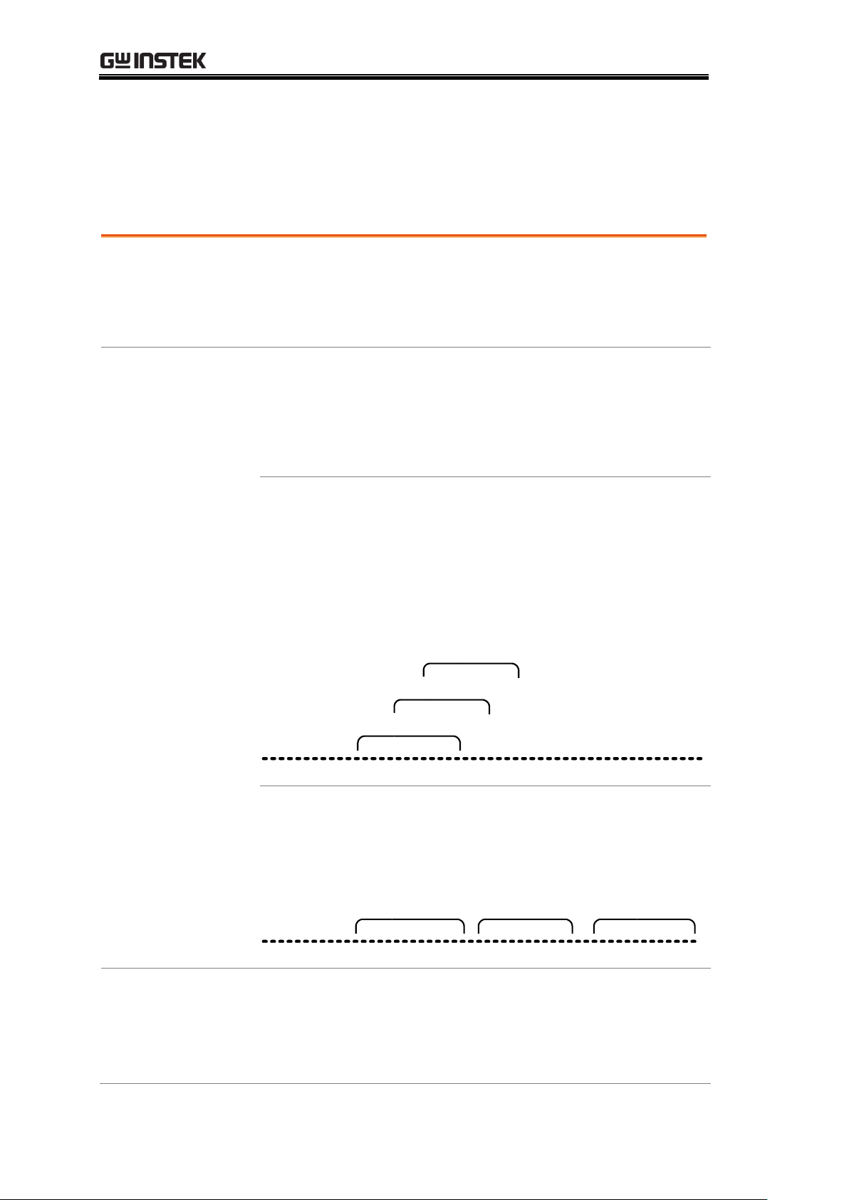
Filter type
The digital filter averages a specific number of input
signal samples to generate one reading. The filter type
defines the averaging method. The following diagrams
show the filter difference as an example of averaging 4
samples per reading.
Moving
(default)
Moving filter takes in one new sample and
discards the oldest sample per reading. This
is the default behavior when the digital filter
is not specified, and is recommended for
most applications except for the optional
scanner operation (page71).
1Sample #
1st reading Sample 1 - 4
2nd reading Sample 2 - 5
32 4 5 6 7 8 9 10 11 12
3rd reading Sample 3 - 6
Repeating
Repeating filter renews the whole samples
per reading. This method is recommended
when using the optional scanner (page71).
1Sample #
1st reading
Sample 1 - 4
2nd reading
Sample 5 - 8
32 4 5 6 7 8 9 10 11 12
3rd reading
Sample 9 - 12
Filter count
Filter count defines the number of samples to be
averaged per reading. More samples offer low noise but
long delay. Less samples offer high noise but short delay.
Range
2 ~ 100
Digital Filter Setting
Overview
62
Page 63

SYSTEM/DISPLAY CONFIGURATION
Turn on Filter
1. Press the Shift key followed by
the MX/MN (Filter) key.
1st display
Shows the filter count
2nd display
Shows the filter type (flashing)
2. Select the filter type using the
Up/Down key.
3. Move the cursor to filter count
using the Left/Right key.
Change the value using the
Up/Down key.
4. Press the ENTER key to
confirm editing. The Filter
indicator appears on the display.
FILT
Indicates manual Filter setting
Turn off Filter
1. Press the Shift key followed by
the MX/MN (Filter) key. The
Filter indicator will disappear
from the display.
Filter setting
63
Page 64

GDM-8200A Series User Manual
Background
Display light setting adjusts the brightness of the display
reading. Use level 3 or more (brighter) when working
indoor; use level 2 or 1 (darker) when working outdoor
under the sun.
Level
5 (brightest) ~ 1 (darkest), default Level 3
Panel operation
1. Press the Shift key followed by
the 2ND (Menu) key. The
system menu appears.
2. Press the Down key, then the
Right key twice. The light menu
appears.
3. Press the Down key. The light
level setting appears.
1st display
Shows the current display light level
4. Select the level using the
Up/Down key.
5. Press the Enter key to confirm
your selection. Press the Exit
key to go back to the default
display.
Display Setting
Display light setting
64
Page 65

SYSTEM/DISPLAY CONFIGURATION
Background
The display can be turned off when not used for a long
time. Note that when this function is used, the panel keys
are also locked except for the Output On/Off key. The
display is turned on by default.
Panel operation
1. Press the Output On/Off key
once. The display will be turned
off and the panel keys become
locked.
2. To enable the display and panel
keys, press the Output On/Off
key again.
Display on/off setting (+ key lock)
65
Page 66

GDM-8200A Series User Manual
Store Measurement Record ............................... 67
Recall Measurement Record .............................. 68
Save Instrument Settings .................................. 69
Recall Instrument Settings ................................ 70
STORE/RECALL
The GDM -8200A Series can store and recall
measurement history (for up to 1000 counts) as well as
the instrument settings. For storing and recalling
measurement results using the Scanner, see page71.
66
Page 67

STORE/RECALL
Background
The GDM-8200A series can store the measurement
history which can be recalled later for observation and
analysis as in Maximum, Minimum, and Average value.
Note: Previously recorded measurements will be erased
every time the store function is used or if power is reset.
Data count
1 ~ 9999
Not applicable to
Store/recall measurement history is not applicable to
Diode/Continuity test .
Store step
1. Press the Shift key followed by
the DCI (Store) key. The store
menu appears.
2. Move the cursor using the
Left/Right key. Change the data
count using the Up/Down key.
3. Press the Enter key to confirm
editing and to go back to the
previous display.
STO
Indicates the measurement history is stored
Store Measurement Record
67
Page 68

GDM-8200A Series User Manual
Background
The GDM-8200A series can recall the stored
measurement history for observation and analysis as in
Maximum, Minimum, and Average value.
Not applicable to
Store/recall measurement history is not applicable to
Diode/Continuity test .
Recall stored
record
Press the Shift key, then the ACI
(Recall) key. The stored
measurement record appears.
1st display
Shows the stored measurement result
2nd display
Shows the reading count
RCL
Indicates the data has been recalled
View each
reading
Change the reading count using the
Up/Down key.
View Max/Min/
Average
Switch to the Average/Maximum/
Minimum value of the recorded data
using the Right key. Use the left key
to go back.
Recall Measurement Record
68
Page 69

STORE/RECALL
Background
The GDM-8200A series can save up to ten instrument
settings. The settings can save the state, function, I/O
and range. Upon powering up, the current instrument
setting is displayed.
Set Instrument
Setting
Press the Shift key, the 2ND key,
Down and then Left twice. The Save
menu appears.
Press the Down key to enter the
Save menu.
Memory Slot
Selection
Choose the memory slot to save to
by using the Up, Down, Left and
Right keys.
Confirm
Selection
Press Enter to confirm the save slot.
Press the Shift key to return to the
measurement screen.
The current instrument settings have been saved.
To enable the settings at power up, follow the
instructions in the next section.
Save Instrument Settings
69
Page 70

GDM-8200A Series User Manual
Background
The Recall function to enables saved settings to be
recalled at power up.
Set Instrument
Setting
Press the Shift key, then the 2ND
(Menu) key, Down and Left once.
The Recall menu appears.
Press the Down key to enter the
Recall menu.
Memory Slot
Selection
Choose the memory slot to recall
from by using the Up, Down, Left
and Right keys.
Confirm
Selection
Press Enter to confirm the memory
slot.
Press the Shift key to return to the
measurement screen
When the instrument is reset or upon the next
power up, the recalled settings will be enabled.
Recall Instrument Settings
70
Page 71

SCANNER (OPTIONAL)
Installation
GDM-SC1 Scanner Specifications .......................... 72
Configure scanner .................................................. 72
Select Channel group and enable scanner.............. 74
Connect wire .......................................................... 75
Insert scanner ........................................................ 77
Scanner Configuration Record ................................ 79
Setup
Overview ................................................................ 80
Setup Simple Scan ................................................. 81
Setup Advanced Scan ............................................. 83
Use external trigger ................................................ 85
Run
Overview ................................................................ 87
Run Scan/Step ....................................................... 87
Recall Scan/Step result .......................................... 88
Setup and run monitoring ...................................... 88
SCANNER (OPTIONAL)
The optional scanner GDM-SC1 lets you effectively
measure multiple channels connected to a single
GDM-8255A Series DMM.
71
Page 72

GDM-8200A Series User Manual
2-wire channel
16 pairs
Maximum current
2A (ch17, ch18)
4-wire channel
8 pairs
Resistance
2/4 wire
Single wire channel
N/A
Cold junction
N/A (internal)
Maximum voltage
250V
Connection
Screw terminal
Open Scanner
cover
1. Take off four screws from the bottom panel of the
scanner.
2. Remove the top panel.
GDM-SC1 Scanner Specifications
Scanner Installation
Configure scanner
72
Page 73

SCANNER (OPTIONAL)
3. The connection terminals appear.
Overview
16 general purpose channels are available, 8 on the left
row, 8 on the right row. Current (ACI, DCI) measurement
uses 2 extra channels. All channels are fully isolated (Hi
and Lo).
Scan/Step
connection
Refer to the below table for measurement and test line
connection.
Item
No. of wire
No. of channels
DCV, ACV
2 wires (H, L)
16 (CH1 ~ 16)
DCI, ACI
2 wires (H, L)
2 (CH17, 18)
2W Resistance
2 wires (H, L)
16 (CH1 ~ 16)
4W Resistance
4 wires (Input H,
L + Sense H, L)
8 pairs (CH1
[input]& 9[sense],
2&10,....8&16)
Diode/Continuity
2 wires (H, L)
16 (CH1 ~ 16)
Period/Frequency
2 wires (H, L)
16 (CH1 ~ 16)
Temperature
2 wires (H, L)
16 (CH1 ~ 16)
73
Page 74

GDM-8200A Series User Manual
Background
2 groups, 16 channels each, are available for the scanner.
Group1
CH101 ~ 118
Group2
CH201 ~ 218
Select group
(Jumper J8)
Set the jumper J8 in the center of the board accordingly.
Move the jumper to the right (pins 2-3) for selecting
CH1xx (101 ~ 118), and move to the left (pins 1-2) for
selecting CH2xx (201 ~ 218).
1 2 3
J8
1
2
3
1
2
3
CH201-218
SLAVE
CH101-118
MASTER
J8
Enable scanner
(Jumper J9)
Set the jumper J9 on the rear side of the board
accordingly. Move the jumper up (pins 3-2) to disable the
scanner, and down (pins 2-1) to enable the scanner.
3
2
1
J9
3
2
1
3
2
1
Enabled
Disabled
J9
Select Channel group and enable scanner
74
Page 75

SCANNER (OPTIONAL)
Wire selection
Make sure the wires have at least the same Voltage and
Current capacity as the maximum ratings in the
measurement.
Connection
1. Turn the screw left (loose) using the screw driver and
insert the wire. Turn the screw right (tight) and
secure the connection.
1 Loosen
2 Insert
3 Tighten
2. Route the wires as follows, using the two openings
(left and right) at the front cover.
Connect wire
75
Page 76

GDM-8200A Series User Manual
Note
When using thermocouple wiring, please use
extension wires so that the cold junction points are
external to the scanner card. Connecting
thermocouple wiring directly to the scanner box is
not recommended due to the radiant heat from the
internal components.
Best if longer
than 20cm
Thermocouple
wire
Cold junction
points
Extension
wires
Hot junction
point
3. Bundle the wires at the front cover using the holes at
the bottom.
4. Close the top cover and tighten the screw from the
bottom.
Configuration
Record
Print out the configuration record list on page79, fill in
the details, and keep it with the GDM-8255A series.
76
Page 77

SCANNER (OPTIONAL)
Power Off
Turn the Power Off and take off the power cord.
Open the
GDM-8200A
series rear pane l
slot
Take off the two screws on the slot corners to remove the
optional slot cover. Keep the screws for later reuse.
Insert scanner
77
Page 78

GDM-8200A Series User Manual
Insert the
scanner
Insert the scanner (already configured according to the
procedures on page72) to either of the two slots, upper or
lower. Close the cover by tightening the screws.
Power On
Connect the power cord and turn On the power.
78
Page 79

SCANNER (OPTIONAL)
Channel
Wire color
Measure type
Note
CH1
H L CH2
H L CH3
H L CH4
H L CH5
H L CH6
H L CH7
H L CH8
H L CH9
H L CH10
H L CH11
H L CH12
H L CH13
H L CH14
H L CH15
H L CH16
H L CH17
H L CH18
H L CARD INPUT
H L CARD SENSE
H L AMPS
H L
Scanner Configuration Record
79
Page 80

GDM-8200A Series User Manual
Scan type
Simple
Sets the scanned channel range, loop
count, and timer length. All channels
have a common measurement item.
Advanced
In addition to the above Simple Scan
setting, allows custom setting for each
channel, such as measurement item,
range, and rate.
Timer setting
Sets the duration between each scan loop (Scan
operation) or between each scanned channel (Step
operation).
Count setting
Sets the number of scan operation (loop).
Trigger setting
Internal
(Continuous)
The GDM-8200A series keeps triggering
continuously until the scan reach the end
of loop count. Then it goes into the idle
mode.
External
(Manual)
The GDM-8200A series stays in the idle
mode by default. The trigger timing is
manually controlled by the user from the
front panel (TRIG key).
Scan operation
Scan
Measures all specified channel range at
each trigger event. Timer setting (page81)
applies between each scan (the whole
channel range).
Step
Measures a single channel in the specified
range at each trigger event. Timer setting
(page81) applies between each channel.
Monitor
Selects just one channel and continuously
measures it.
Setup Scan
Overview
80
Page 81

SCANNER (OPTIONAL)
Panel operation
1. Press the Shift key, the 2
ND
key
(MENU), the Left key. The Scan
menu appears.
2. Press the Down key. The Simple
Scan menu appears.
3. Press the Down key again. The
Starting (Minimum) channel
setting appears.
4. Move the cursor to the channel
using the Left/Right key, and
change the value using the
Up/Down key.
Range
101 ~ 118, 201 ~ 218
5. When finished, press the
ENTER key. The End
(Maximum) channel setting
appears.
Setup Simple Scan
81
Page 82

GDM-8200A Series User Manual
6. Move the cursor to the channel
using the Left/Right key, and
change the value using the
Up/Down key.
Range
101 ~ 118, 201 ~ 218 (must be the same
or bigger than the Start (Min) channel)
7. When finished, press the
ENTER key. The Timer setting
appears.
8. Move the cursor to the channel
using the Left/Right key, and
change the value using the
Up/Down key.
Range
1ms ~ 9999ms
9. Press the ENTER key. The loop
(step) Count setting appears.
10. Move the cursor to the channel
using the Left/Right key, and
change the value using the
Up/Down key.
Range
1 ~ 999
11. Press the ENTER key followed
by the EXIT key. The setting is
stored and the display goes back
to the normal mode.
82
Page 83

SCANNER (OPTIONAL)
Panel operation
1. Press the Shift key, the 2
ND
key
(MENU), the Left key. The Scan
menu appears.
2. Press the Down key followed by
the Right key. The Advanced
Scan menu appears.
3. Press the Down key. The
Starting (Minimum) channel
setting appears.
4. Move the cursor to the channel
using the Left/Right key, and
change the value using the
Up/Down key.
Range
101 ~ 118, 201 ~ 218
5. When finished, press the
ENTER key. The End
(Maximum) channel setting
appears.
Setup Advanced Scan
83
Page 84

GDM-8200A Series User Manual
6. Move the cursor to the channel
using the Left/Right key, and
change the value using the
Up/Down key.
Range
101 ~ 118, 201 ~ 218 (must be the same
or bigger than the Start (Min) channel)
7. When finished, press the
ENTER key. The Timer setting
appears.
8. Move the cursor to the channel
using the Left/Right key, and
change the value using the
Up/Down key.
Range
1ms ~ 9999ms
9. When finished, press the
ENTER key. The Count setting
appears.
Range
1 ~ 999
10. Move the cursor to the channel
using the Left/Right key, and
change the value using the
Up/Down key.
11. When finished, press the
ENTER key. The channel
setting appears.
12. The Minimum (first) scanned channel, as set in the
Simple Scan setting, appears. The default setting is
CH101.
84
Page 85

SCANNER (OPTIONAL)
13. Set the measurement condition.
To select measurement item,
press the target key.
To select Auto range, press
the AUTO key.
To manually select the range,
press the Up/Down key.
14. When finished, press the Right
key to confirm edit and to move
to the next channel.
15. When all channel configurations
are completed, press the EXIT
key. The display goes back to
the default mode.
85
Page 86

GDM-8200A Series User Manual
Background
The GDM-8200A series uses the internal trigger by
default. Using an external trigger allows customized
triggering.
Signal
connection
Connect the external trigger signal to the Digital I/O
port located on the rear panel.
DB-9, female
Digital I/O pin
assignment
1 2 3 4 5
6 7 8 9
FAIL Out
HIGH Limit FAIL Out
LOW Limit FAIL Out
EOM Out
VCC Out
NC
Digital (Chassis) Ground
External Trigger In
PASS Out
Pin4
External Trigger Input pin
Activate external
trigger
Press the Shift key followed by the
TRIG key. The EXT indicator
appears on the display.
Start trigger
Press the TRIG key to start
triggering manually. The reading
indicator ( ) turns On.
Reading indicator
The reading indicator stays On before triggering.
After triggering, the indicator flashes according to the
external signal trigger timing.
Exit external
trigger
Press the Shift key followed by the
TRIG key. The EXT indicator
disappears and the trigger goes back
to the internal mode.
Use external trigger
86
Page 87

SCANNER (OPTIONAL)
Scan operation
type
Scan
Measures all specified channel range at
each trigger event. Timer setting (page81)
applies between each scan.
Step
Measures a single channel in the specified
range at each trigger event. Timer setting
(page81) applies between each channel.
Monitor
Continuously measure one channel.
Activate
Scan/Step
1. Press the Shift key followed by
the ACV key (SCAN) or DCV
key (Step).
2. The STO indicator turns On. The Scan (Step) starts
running and the data is recorded. After running the
predefined count, the Scan (Step) stops running.
Retrigger/Restart
Scan
To run the Scan (Step) again, press
the TRIG key. The previous data is
overwritten by the new Scan.
Abort Scan/Step
To abort Scan/Step or to go back to
the normal display, press the Shift
key followed by the ACV key (Scan)
or DCV key (Step) again.
Run Scan
Overview
Run Scan/Step
87
Page 88

GDM-8200A Series User Manual
Panel operation
1. After the Scan/Step is
completed, the data is stored
internally. Press the Shift key
followed by the ACI (Recall) key.
2. The first channel appears. (example: channel 101)
3. To view the Max/Min/Average
data, press the Left and Right
keys.
4. To move to the next channel,
press the Up/Down key.
5. Press the EXIT key to get out
from recall mode.
Panel operation
1. Press the Shift key, the 2
ND
key
(MENU), the Left key. The Scan
menu appears.
2. Press the Down key followed by
the Left key. The Monitor Scan
setting menu appears.
Recall Scan/Step result
Setup and run monitoring
88
Page 89

SCANNER (OPTIONAL)
3. Press the Down key. The
channel selection appears.
4. Move the cursor to the channel
using the Left/Right key, and
change the value using the
Up/Down key.
5. When finished, press the
ENTER key. The Monitoring
starts.
89
Page 90

GDM-8200A Series User Manual
Terminal
configuration
Digital I/O Terminal Configuration ........................ 91
Application
Application: Compare measurement ...................... 92
Application: External trigger .................................. 94
DIGITAL I/O
The rear panel Digital I/O terminal outputs the result of
Compare measurement to external devices.
90
Page 91

DIGITAL I/O
Background
The digital I/O terminal outputs the result of Compare
measurement to control external devices. By providing
separate VCC for the terminal, the outputs can also be
used as power source for TTL and CMOS logics.
Pin assignment
Connector type: DB-9 female
1 2 3 4 5
6 7 8 9
FAIL Out
HIGH Limit FAIL Out
LOW Limit FAIL Out
EOM Out
VCC Out
NC
Digital (Chassis) Ground
External Trigger In
PASS Out
Pin1
VCC output, 5V. Serves as the power source for
the external device/logic.
Pin2
NC (No Connection).
Pin3
COM (ground).
Pin4
External Trigger Input. Accepts external trigger
signal. For using external signals, see page86
(Scanner) or page59 (Configuration).
Pin5
PASS signal Output. Activates when the
compare result is PASS.
Pin6
FAIL signal Output. Activates when the
compare result is FAIL.
Pin7
HIGH Limit FAIL signal Output. Activates
when the compare result is FAIL due to
violating the HIGH Limit.
Pin8
LOW Limit FAIL signal Output. Activates when
the compare result is FAIL due to violating the
LOW Limit.
Pin9
EOM (End Of Measurement) signal Output.
Activates when compare measurement is over.
Digital I/O Terminal Configuration
91
Page 92

GDM-8200A Series User Manual
Applicable to
( )
+
( )
+
Background
Compare measurement checks and updates if the
measurement data stays between the upper (high) and lower
(low) limit specified.
1. Activate
Compare
measurement
Press the Shift key, then the
HOLD (Comp) key.
2. High limit
setting
1st display
Shows the high limit value
2nd display
Indicates high limit setting
1. Use the Left/Right key to
move the cursor (flashing
point) between high/low
setting, digits, and decimal
point.
2. Change the parameter using
the Up/Down key.
3. Press the ENTER key to
confirm editing and move
to the low limit setting.
3. Low limit
setting
1st display
Shows the low limit value
2nd display
Indicates low limit setting
Application: Compare measurement
92
Page 93

DIGITAL I/O
Set the low limit in the same way
as in the high limit. Press the
ENTER key to confirm editing.
The compare measurement
starts right away.
4. Compare
measurement
appears
COMP
Indicates Compare mode
2nd display
Shows the compare measurement result:
Pass, High, or Low.
5. Result
High
If the 2nd display
shows High, the
result is above the
High limit.
Digital I/O: FAIL Out (Pin 6) and HIGH
Limit FAIL Out (Pin 7) are activated.
Low
If the 2nd display
shows Low, the
result is below the
Low limit.
Digital I/O: FAIL Out (Pin 6) and LOW
Limit FAIL Out (Pin 8) are activated.
Pass
If the 2nd display
shows Pass, the
result is staying
between the High
and the Low limit.
Digital I/O: PASS Out (Pin 5) is activated.
Deactivate
Compare
measurement
To cancel the Compare
measurement, press the Shift
key followed by the HOLD
(Comp) key, or simply activate
another measurement.
93
Page 94

GDM-8200A Series User Manual
Background
The GDM-8200A series uses the internal trigger by
default, for example to count the frequency and the
period. Using an external trigger allows customized
triggering condition.
Signal
connection
Connect the external trigger signal to the Digital I/O
port located on the rear panel.
1 2 3 4 5
6 7 8 9
FAIL Out
HIGH Limit FAIL Out
LOW Limit FAIL Out
EOM Out
VCC Out
NC
Digital (Chassis) Ground
External Trigger In
PASS Out
Pin4
External Trigger Input pin
1. Activate
external trigger
Press the Shift key followed by the
TRIG key. The EXT indicator
appears on the display.
2. Start trigger
Press the TRIG key to start
triggering manually. The
indicator turns On.
Reading indicator
The reading indicator stays On before triggering.
After triggering, the indicator flashes according to the
external signal trigger timing.
Exit external
trigger
Press the Shift key followed by the
TRIG key. The EXT indicator
disappears and the trigger goes back
to internal mode.
Application: External trigger
94
Page 95

REMOTE CONTROL
Interface
Overview ................................................................ 96
Configure USB interface ........................................ 96
Configure RS-232C interface .................................. 97
Command Syntax
Command Syntax ................................................... 99
Command Set
CONFigure command ...........................................100
SENSe command ..................................................101
UNIT command ....................................................102
TRIGger command ...............................................104
SYStem related command ....................................105
STAtus reporting command ..................................105
RS-232C interface command ................................105
IEEE 488.2 common command .............................105
ROUTe command .................................................106
CONFigure2 command .........................................107
REMOTE CONTROL
95
Page 96

GDM-8200A Series User Manual
Interface type
USB Device
USB 1.1 or 2.0, TypeA, female
connector.
RS-232C
D-sub 9 pin, male connector. Baud
rate: 115200/57600/38400/19200/
9600.
Return to Local
control mode
In order to switch back to the
Local control mode (front panel
operation), press the LOCAL key.
USB device port
configuration
1. Press the Shift key, the 2ND
(Menu) key, the Right key
twice. The I/O configuration
menu appears.
2. Press the Down key. The USB
selection display appears.
3. Press the Down key. The USB
ON/OFF selection appears.
4. Press the Up/Down key to
select ON or OFF.
Configure Interface
Overview
Configure USB interface
96
Page 97

REMOTE CONTROL
5. Press the ENTER key to
confirm USB selection.
6. Press the Exit key to go back
to the default display.
7. Connect the USB cable to the
rear panel terminal (upper
port).
CAL KEY
Configuration step
1. Press the Shift key, the 2ND
(Menu) key, the Right key
twice. The I/O configuration
menu appears.
2. Press the Down key, then the
Right key. The RS-232C
selection display appears.
3. Press Enter or Down to confirm
RS232 selection.
or
4. Press the Down or UP keys
repeatedly to select the baud
rate.
1152005760038400192009600
5. Press the ENTER key to
confirm RS-232C and baud
rate selection.
Configure RS-232C interface
97
Page 98

GDM-8200A Series User Manual
6. Press the Exit key to go back
to the default display.
7. Connect the RS-232C cable to
the rear panel terminal.
RS-232C pin
assignment
Pin 2: RxD
Pin 3: TxD
Pin 5: GND
Pin 1, 4, 6 ~ 9: No Connection
5 4 3 2 1
9 8 7 6
PC – GDM
RS-232C
Connection
Null-modem connection, in which transmit (TxD) and
receive (RxD) lines are cross-linked, is required.
GDM PC
TxD
RxD
GND
Pin2
Pin3
Pin5
TxD
RxD
GND
Pin2
Pin3
Pin5
98
Page 99

REMOTE CONTROL
Example command
conf:volt:dc _1
1 2 3
1: Command Header
2: Single space
3: Parameter
Parameter example
Boolean
Boolean logic: 0 or 1. Used for On (1) or
Off (0) command.
NR1
Integer: 0, 1, 2, 3.....
NR2
Decimal number: 0.0, 0.1, 0.2,....
NR3
Floating point number: 4.5e-1, 8.5e+1,...
min, max
The GDM-8200A series automatically
translates to Minimum (min) or Maximum
(max) value available.
Automatic
parameter range
selection
The GDM-8200A series automatically translates the
command parameter into the closest available value.
Example 1
conf:volt:dc_1 (Sets the measurement
item to DC Voltage and the range to 1V).
the GDM-8200A series selects the 1V
range.
Example 2
conf:volt:dc_2 (Sets the measurement
item to DC Voltage and the range to 2V).
There is no 2V range so the
GDM-8200A series selects the closest
range, 10V.
Message
Terminator (EOL)
Remote
Command
Marks the end of a command line. The
following messages are in accordance
with IEEE488.2 standard.
LF, CR or CR+LF
The most common
ELO character is
CR+LF.
Return
Message
LF+CR
The fixed and only
option.
Message Separator
; (semicolon)
Command Separator
Command Syntax
The commands are partially compatible with IEEE488.2 (1992) and SCPI
(1994) standard. Commands are NON-case sensitive.
99
Page 100

GDM-8200A Series User Manual
conf:volt:dc
Sets measurement to DC Voltage and specifies range.
Parameter: NR2, min, max
Example: conf:volt:dc_1 (DCV, 1V range)
Example: conf:volt:dc_min (DCV, minimum range)
conf:volt:ac
Sets measurement to AC Voltage and specifies range.
Parameter: NR2, min, max
Example: conf:volt:ac_1 (ACV, 1V range)
Example: conf:volt:ac_min (ACV, minimum range)
conf:volt:dcac
Sets measurement to DC+AC Voltage and specifies range.
Parameter: NR2, min, max
Example: conf:volt:dcac_1 (DC+ACV, 1V range)
Example: conf:volt:dcac_min (DC+ACV, minimum range)
conf:curr:dc
Sets measurement to DC Current and specifies range.
Parameter: NR2, min, max
Example: conf:curr:dc_10e-3 (DCI, 10mA range)
Example: conf:curr:dc_min (DCI, minimum range)
conf:curr:ac
Sets measurement to AC Current and specifies range.
Parameter: NR2, min, max
Example: conf:curr:ac_10e-2 (ACI, 100mA range)
Example: conf:curr:ac_min (ACI, minimum range)
conf:curr:dcac
Sets measurement to DC+AC Current and specifies range.
Parameter: NR2, min, max
Example: conf:curr:dcac_10 (DC+ACI, 10A range)
Example: conf:curr:dcac_min (DC+ACI, minimum range)
conf:res
Sets measurement to 2W Resistance and specifies range.
Parameter: NR2, min, max
Example: conf:res_10e3 (2W R, 10K range)
Example: conf:res_min (2W R, minimum range)
conf:fres
Sets measurement to 4W Resistance and specifies range.
Parameter: NR2, min, max
Example: conf:fres_10e3 (4W R, 10K range)
Example: conf:fres_min (4W R, minimum range)
conf:freq
Sets measurement to Frequency and specifies range.
Command Set
Commands are non-case sensitive.
Underline means a single space (dc_1→DC 1V).
When the parameter does not match the real value, the closest possible
option is automatically selected (dc_2 [DC 2V range]→DC 10V)
CONFigure command
100
 Loading...