

Page 1

Handheld Digital Multimeter
GDM-350B
USER MANUAL
GW INSTEK PART NO. 82DM-350B0M01
ISO-9001 CERTIFIED MANUFACTURER
Page 2

This manual contains proprietary information, which is protected by copyright. All
rights are reserved. No part of this manual may be photocopied, reproduced or
translated to another language without prior written consent.
The information in this manual was correct at the time of printing. However, we
continue to improve our products and therefore reserve the right to change the
specifications, equipment, and maintenance procedures at any time without notice.
Good Will Instrument Co., Ltd. No. 7-1, Jhongsing Rd., Tucheng Dist., New Taipei City 236, Taiwan.
Page 3

Table of Contents
Table of Contents
OVERVIEW............................................................................................................................. 2
Unpacking & Inspection ................................................................................................................... 3
Safety Information............................................................................................................................. 4
International Electrical Symbols ....................................................................................................... 6
Overall Specification ......................................................................................................................... 7
The Meter Structure .......................................................................................................................... 8
MEASUREMENT OPERATION ............................................................................................. 9
DC or AC Voltage Measurement .................................................................................................... 10
DC Current Measurement .............................................................................................................. 12
Resistance Measurement ............................................................................................................... 14
Diode Measurement ....................................................................................................................... 16
Continuity Measurement ................................................................................................................ 18
Transistor hFE measurement ......................................................................................................... 20
Temperature Measurement ............................................................................................................ 22
ACCURACY SPECIFICATIONS ............................................................................................ 24
MAINTENANCE .................................................................................................................. 30
General Service and Maintenance .................................................................................................. 30
Replacing the Battery and Fuse ...................................................................................................... 31
1
Page 4

GDM-350B User Manual
OVERVIEW
The GDM-350B multimeter is a hand-held 3 1/2digit multimeter with an advanced
design, multiple functions and reliable performance. This meter is fully capable of
measuring both AC and DC voltage, DC current, resistance, temperature, the
forward voltage drop of diodes, transistors, hFE and continuity tests. The multipurpose socket is used to measure SMTs as well. This operating manual covers
information on safety and precautions to fulfill CE standards. Please read the
relevant information carefully and observe all the warnings and notes.
Warning
To avoid electric shock or personal injury, read the “Safety Information”
carefully before using the Meter.
2
Page 5
OVERVIEW
Item
Description
Qty 1 Operating Manual
1 piece
2
Test Leads
1 pair
3
K-type Temperature Probe
(Nichrome-Nickel Aluminum Thermocouple)
1 piece
4
Multi-Purpose Socket
1 piece
Unpacking & Inspection
Open the package case and take out the Meter. Check the following items carefully
to see if any parts are missing or damaged:
In the event that you find any parts missing or damaged, please contact your dealer
immediately.
3
Page 6

GDM-350B User Manual
Safety Information
This meter complies with the IEC/EN61010-1 standard, pollution degree 2,
overvoltage category (CAT III 250V) with double insulation. Only use the meter as
specified in this operating manual, otherwise the protection provided by the meter
may be impaired.
1. Before using the meter inspect the case. Do not use the meter if it is damaged
or if the case (or part of the case) is removed. Look for cracks or missing plastic.
Pay attention to the insulation around the connections.
2. Inspect the test leads for damaged insulation or exposed metal. Before using
the meter replace any damaged test leads with test leads of the same model
number or of the same electrical specifications
3. Replace the battery as soon as the battery indicator “ ” appears. With a low
battery, the meter might produce false readings that can lead to electric shock
and personal injury.
4. Turn measurement on only if the correct input terminals are used.
5. Do not apply more than the rated voltage, as marked on the meter in order to
avoid possible electric shock or personal injury and to avoid possible damage
to the meter
6. Do not change the measuring range during the testing as it causes damage to
the meter.
4
Page 7

OVERVIEW
7. When each measurement has been completed, disconnect the test leads from
the DUT and then turn the power off from the meter. Remove the test leads
from the input terminals of the meter. This is vital for high current
measurement.
8. When the meter is working at an effective voltage over 60V in DC or 30Vrms in
AC, special care should be taken.
9. Do not use or store the meter in an environment with high temperature and
humidity. The performance of the meter may deteriorate if dampened.
10. The internal circuit of the meter should not be tampered with. To avoid
damage to the meter when cleaning, use soft cloth and mild detergent to clean
the surface of the meter when servicing. No abrasives or solvent should be
used to prevent the surface of the meter from corrosion and damage.
5
Page 8
GDM-350B User Manual
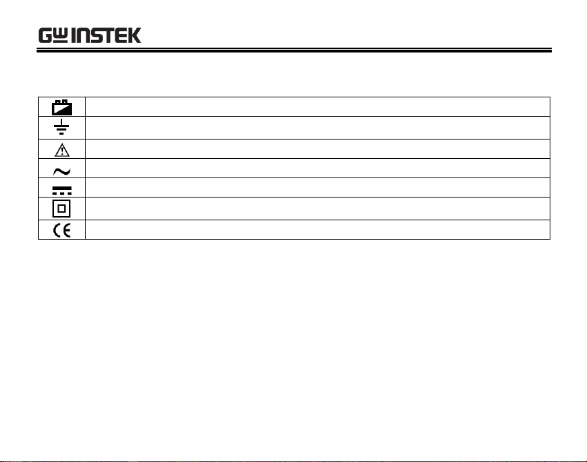
Battery has insufficient charge
Ground
Warning: Refer to the Operating Manual
AC (Alternating Current)
DC (Direct Current)
Double Insulated
Conforms to Standard of European Union
International Electrical Symbols
6
Page 9

OVERVIEW
Overall Specification
1. Maximum voltage between any terminal and ground: Refer to the different
input protection voltage ranges shown on the terminals.
2. 10A terminal: Set (CE) 10A H 240V Fast Type Ceramic Fuse φ6x25mm.
3. mA terminal: Set (CE) 1 A H 240V Fast Type Ceramic Fuse φ6x25mm.
4. Operating temperature: 0˚C~40˚C, 32˚F ~104˚F.
Relative Humidity: 0˚C ~30˚C below ≤75%, 30˚C ~40˚C below ≤50%.
Storing temperature:-10˚C ~50˚C (14˚F ~122˚F).
5. Electromagnetism:
Under 1V/m emission: Best Total Accuracy= Specific Accuracy +
Measurement 5%, Over 1V/m emission does not have any specific index.
6. Elevation: 0~2000m.
7. Internal battery: 9V 6F22 or NEDA 1604 or 006P.
8. Low Battery: indicated by “ ” on the LCD display.
9. Product size: 72mm×137mm×35mm.
10. Net Weight: About 200g (battery included).
11. Safety Standard:
IEC/EN 61010-1: CATIII 250V, Pollution Degree 2.
12. Conformance: CE.
7
Page 10
GDM-350B User Manual
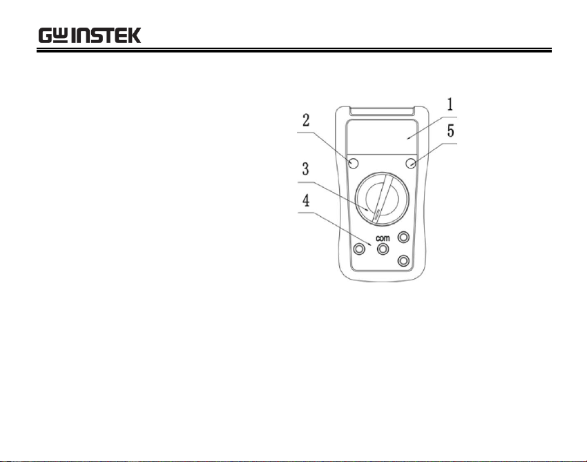
The Meter Structure
(see diagram 1)
1. LCD Display
2. Power Button
3. Rotary Switch
4. Input Terminals
5. HOLD Button
diagram 1
8
Page 11

MEASUREMENT OPERATION
MEASUREMENT OPERATION
First check to see that the 9V battery is charged. Turn the rotary switch to a
measurement position. If the battery charge is low, the “ ” indicator will be
displayed on LCD panel. Ensure the input voltage or current does not exceed
250Vrms and 10A, respectively.
9
Page 12

GDM-350B User Manual
DC or AC Voltage Measurement
(see diagram 2)
Diagram 2
1. Turn the rotary switch to the V or V position for voltage measurement.
2. Insert the red test lead into the “V” terminal and the black test lead into the
“COM” terminal, Connect the test leads to the DUT being measured. The
measured value shows the true root mean square voltage (for stable inputs).
3. For each range, the meter has an input impedance of 10MΩ. Input impedance
for V is about 4.5MΩ. This loading effect can cause measurement errors in
10
Page 13

MEASUREMENT OPERATION
high impedance circuits. If the circuit impedance is less than or equal to 10kΩ,
the error is negligible (0.1% or less).
Warning:
To avoid damage to the meter, please do not attempt to input more than 250V.
To avoid electrical shock, please pay attention during high voltage
measurement.
11
Page 14

GDM-350B User Manual
DC Current Measurement
(see diagram 3)
Diagram 3
1. Turn the rotary switch to the “A “ position for current measurement.
2. Insert the red test lead into the “mA” or “10A” terminal, and the black test lead
into the “COM” terminal. Connect the test leads to the DUT being measured.
The measured value shows on the display.
12
Page 15

MEASUREMENT OPERATION
Warning:
Pre-requisites: Remove the power from the circuit before connecting the test
leads to the DUT.
Select the correct terminal input and turn the rotary switch to select the
measurement function. If the correct range is not known, select the highest
range and work your way down to a lower range if needed.
Fuses are located on the mA and 10A current input terminals. Never attempt
connecting the test leads to any circuits that are connected to mains power.
For safety purposes, ensure each measurement over 5A is performed for less
than 10 seconds with a 15 minute interval between measurements.
13
Page 16

GDM-350B User Manual
Resistance Measurement
(see diagram 4)
Diagram 4
1. Turn the rotary switch to the “Ω” position for resistance measurement.
2. Insert the red test lead into the “Ω” terminal and the black test lead into the
“COM” terminal. Connect the test leads to the DUT being measured. The
measured value shows on the display.
14
Page 17

MEASUREMENT OPERATION
Warning:
If the LCD displays “1”, it indicates the circuit is open or that the resistance
exceeds the maximum range of the meter.
To maintain the resistance measurement accuracy, remove circuit power and
discharge all high voltage capacitors when measuring resistance.
The test leads cause a resistance drop of 0.1Ω ~0.2Ω. In order to obtain precise
readings for low-resistance measurements, the resistance of the test leads must
be deducted from the measured resistance. Short the test leads and note the
measurement result. Deduct this value from the resistance of the DUT.
Measured Result of DUT – Resistance of test leads = Actual measurement.
If a resistance reading with shorted test leads is not less than or equal to 0.5Ω,
check for possible problems such as loose test leads or an incorrectly selected
function.
For resistance measurements greater than 1MΩ, it may take several seconds to
obtain a stable reading.
Do not input greater than DC 60V and AC 30V to prevent damage and injury.
15
Page 18

GDM-350B User Manual
Diode Measurement
(see diagram 5)
Diagram 5
1. Turn the rotary switch to the “ ” position for diode measurement.
2. Insert the red test lead into the “ ” terminal and the black test lead into the
“COM” terminal. The red test lead is “+”, the black test lead is “-”.
3. In a circuit, a good diode should still produce a forward voltage drop reading
of 500~800mV. However, a reverse voltage drop reading can vary depending
on the resistance of other pathways between the probe tips.
16
Page 19

MEASUREMENT OPERATION
Warning:
The LCD displays “1” to indicate that the circuit is open or that the polarity of
the diode is incorrect.
To ensure the accuracy of the diode measurement, disconnect power from the
circuit and discharge all high voltage capacitors during the measurement.
The open circuit voltage for diodes is 2.3V.
Do not input greater than DC 60V and AC 30V to prevent damage and injury.
17
Page 20

GDM-350B User Manual
Continuity Measurement
(see diagram 6)
Diagram 6
18
Page 21

MEASUREMENT OPERATION
ΩmA
1. Turn the rotary switch to the “ ” position.
2. Insert the red test lead into the “
” terminal and the black test lead into the
“COM” terminal. If the resistance between both terminals is >70Ω, it indicates
an open-circuit and no buzzer will sound, but if the resistance between both
terminals is ≤10Ω, it indicates a good connection and the buzzer will sound.
The resistance measurement is displayed on the LCD (Unit: Ω).
Warning:
To maintain measurement accuracy, disconnect circuit power and discharge all
the high voltage capacitors during continuity measurement.
For continuity testing, the open circuit for voltage is 2.3V.
Do not input higher than DC 60V and AC 30V voltage to prevent any damage
and injury.
19
Page 22

GDM-350B User Manual
Transistor hFE measurement
(see diagram 7)
Diagram 7
20
Page 23

MEASUREMENT OPERATION
1. Turn the rotary switch to the “hFE” position.
2. Put the multi-purpose socket into the terminal.
3. Check whether the transistor is either PNP or NPN or SMT, then connect the
transistor to be measured to the corresponding jacks.
4. The LCD display shows the hFE reference value. The testing requirement: basic
current 10µA,Vce of 2.3V.
Warning:
To avoid damage to the Meter or to the DUT, do not input any voltage over
60V DC or 30V AC.
Take off the multi-purpose socket after the measurement.
21
Page 24

GDM-350B User Manual
Temperature Measurement
(see diagram 8)
Diagram 8
22
Page 25

MEASUREMENT OPERATION
1. Turn the rotary switch to the “˚C” position.
2. Put the multi-purpose socket into the correct terminal.
3. The K-type thermocouple can only be used for measurements below 230˚C, if
you want to measure over 230˚C, you need to buy another type of
thermocouple.
4. When the LCD displays “1”, it indicates that the K-type thermocouple is not
connected. When the ˚C terminal and the COM terminal are shorted, the meter
will show the room temperature.
Warning:
Keep the thermocouple clean to prevent the contact point from having any
serious influence on measurements.
Remove the contact point after temperature measurement and store in good
condition.
23
Page 26

GDM-350B User Manual
Range
Resolution
Accuracy
200mV
0.1mV
±(0.5% Reading + 2 Digits)
2000mV
1mV
20V
0.01V
200V
0.1V
250V
1V
±(0.8% Reading + 2 Digits)
ACCURACY SPECIFICATIONS
Accuracy: ±(a% reading + b digits), guaranteed for 1 year
Operating temperature: 23˚C ± 5˚C
Relative Humidity: <75%
DC Voltage
Input impedance: all range 10MΩ.
Maximum input voltage: 250V DC.
24
Page 27

ACCURACY SPECIFICATIONS
Range
Resolution
Accuracy
200V
0.1V
±(1.2 Reading% +3 Digits)
250V
1V
AC Voltage
Input impedance: about 4.5MΩ;
Frequency: 45Hz~400Hz.
Display: effective value of a sine wave (average value) each measurement is
applicable from 5% of range as reference.
Maximum input voltage: 250V AC.
25
Page 28

GDM-350B User Manual
Range
Resolution
Accuracy
2000µA
1µA
±(1% Reading +2 Digits)
20mA
0.01mA
±(1% Reading + 2 Digits)
200mA
0.1mA
±(1.2% Reading +2 Digits)
10A
0.01A
±(2% Reading +5 Digits)
DC Current
Overload Protection:
mA range: F2 fuseφ6×25mm, F 1A H 240V (CE)
10A range: F1 fuseφ6×25mm, F 10A H 240V (CE)
Warning:
When ≤ 5A Continuous measurement is allowed.
When > 5A Measurements must not take longer than 10 seconds with a wait of 15
minutes between measurements.
26
Page 29

ACCURACY SPECIFICATIONS
Range
Resolution
Accuracy
200Ω
0.1Ω
±(0.8% Reading + 5 Digits)
2000Ω
1Ω
20kΩ
0.01kΩ
200kΩ
0.1kΩ
2000kΩ
1kΩ
20MΩ
0.01MΩ
±(1% Reading + 5 Digits)
Resistance
Overload Protection: 250V AC or DC
27
Page 30

GDM-350B User Manual
Range
Resolution
Accuracy
-40˚C~ -20˚C
1˚C
-(8% Reading + 5 digits)
-20˚C~0˚C
± 4 digits
> 0˚C~100˚C
±(1.0% Reading + 3 digits)
>100˚C~1000˚C
±(2.5% Reading + 2 digits)
Temperature Measurement
Overload Protection: 250V DC or AC
The enclosed K-type thermocouple can only be used for temperature
measurements less than 230˚C.
28
Page 31

ACCURACY SPECIFICATIONS
Function
Range
Resolution
Remark
Diode
1mV
Display positive voltage decline
Transistor
hFE
1
Function
Range
Resolution
Remark
Continuity Test
1Ω
<10Ω Buzzer beeps continuously
Diode, Transistor
Continuity Test
Overload Protection: 250V DC or AC.
29
Page 32

GDM-350B User Manual
MAINTENANCE
Warning
Make sure the test leads are removed and the power is turned off the meter
before opening the cover.
General Service and Maintenance
Periodically wipe the case with a damp cloth and mild detergent. Do not use
abrasives or solvents.
If there are any abnormalities in the meter, stop using the meter and return to an
authorized service center.
When the meter needs to be calibrated, return the unit to an authorized service
center.
30
Page 33

MAINTENANCE
Replacing the Battery and Fuse
(see diagram 12)
Warning
On the LCD display, the battery warning indicator, “ ” indicates the battery is
low and needs to be replaced with a new battery. Failure to replace the battery
causes the measured result to be unstable.
Battery Specification: 9V 6F22 or NEDA 1604 or 006P
(diagram 12)
31
Page 34

GDM-350B User Manual
Operating Steps:
1. Turn the power off and remove the test leads from the meter.
2. Use a screwdriver to remove the screws from the battery cover. The old battery
can now be removed.
3. The fuses can be replaced by using a screwdriver to remove the two screws
holding the fuses in place. Only replace fuses with the same type and
specifications.
Fuse specification:
F1 Fuseφ6×25mm, F 10A H 240V
F2 Fuseφ6×25mm, F 1A H 240V
32
 Loading...