

GW Instek GCM-407 User Manual
GCM-407 User Manual
I. Overview - - - - - - - - - - - - - - - - - - - - - - - - - - 1
II. Open-case Inspection - - - - - - - - - - - - - - - - - 1
III. Safety Operation Guidelines - - - - - - - - - - - - 2
IV. Electrical Symbols - - - - - - - - - - - - - - - - - - - 4
V. External Construction - - - - - - - - - - - - - - - - - 5
VI. Display Symbols - - - - - - - - - - - - - - - - - - - - 6
VII. Key Functions - - - - - - - - - - - - - - - - - - - - - 7
VIII. Technical Indicators - - - - - - - - - - - - - - - - - 8
1. General Specifications - - - - - - - - - - - - - - - 8
2. Environmental Restraints - - - - - - - - - - - - - 9
3. Electrical Specifications - - - - - - - - - - - - - 10
IX. Measurement Operating Instructions- - - - - 13
1. AC Current Measurement- - - - - - - - - - - - 13
2. AC voltage Measurement - - - - - - - - - - - - 15
3. DC voltage Measurement - - - - - - - - - - - - 17
4. Resistance Measurement - - - - - - - - - - - - 18
5. Continuity Test- - - - - - - - - - - - - - - - - - - - 19
6. Diode Measurement- - - - - - - - - - - - - - - - 21
7. Capacitance Measurement - - - - - - - - - - - 22
8. Non-contact AC Voltage Sensing NCV- - - 24
9. Power- - - - - - - - - - - - - - - - - - - - - - - - - - 25
10. Automatic Shutdown Function- - - - - - - - 25
X. Maintenance and Upkeep - - - - - - - - - - - - - 25
1. General Maintenance- - - - - - - - - - - - - - - 25
2. Installation or Replacement of the Batteries 25

GCM-407 User Manual
GCM-407 User Manual
I. Overview
GCM-407 is a portable, true 6000 count, auto range
clamp ammeter with a simulation bar. Featuring a
large scale integrated circuit, Σ/∆ analog-digital
converter, full-function on-screen display, full-range
overload protection and a unique design has given
this specific clamp ammeter superior performance.
The clamp ammeter is applicable to the following
measurements: AC/DC voltage, AC current,
resistance, diode, continuity, capacitance,
data-hold, maximum/minimum value measurement,
relative value measurement, flashlight function,
VFC function, NCV function, under-voltage display
and an automatic shutdown function.
The instruction manual includes relevant safety
information and warning indicators. Please read
them carefully and strictly observe all warnings and
notes.
Warning:
Prior to using the clamp meter, please read the
relevant "Safety operation guidelines" carefully.
II. Open-case Inspection
Unpack and take out the instrument. Carefully
check that the following accessories are not
damaged or missing.
1.An operating instruction manual
2.Test leads
3.Carrying case
If anything is missing or damaged, please contact
your GW Instek distributor. If the instrument is not
used in an appropriate manner the safety protections could be impaired. The unit can be used for
MAINS measurements up to CATII 1000V or CATIII
600V according to IEC 61010-031.
III. Safety Operation Guidelines
Please note the “warning signs” and notes.
Warnings indicate a condition or action that may
cause a threat to the user or may damage the
instrument or the equipment under test.
This meter complies with EN61010-1, 61010-2-032,
61010-2-033, Pollution Degree 2, Overvoltage
Category (CATII 1000V, CATIII 600V) and double
insulation standards.
Conforms to UL STD 61010-1 and IEC STD
61010-2-032
Certified to CSA STD C22.2 No.61010-1 and
61010-2-032.
This product has been tested to the requirements
of CAN/CSA-C22.2 No. 61010-1, second edition,
including Amendment 1.
CAT II: Applicable to test and measurement circuits
connected directly to utilization points (socket
outlets and similar points) of the low-voltage MAINS
installation.
CAT III: Applicable to the test and measurement
circuits connected to the distribution part of the
building’s low-voltage MAINS installation.
1. Check the clamp ammeter and test leads before
use. Refrain from using the clamp if the clamp is
damaged in anyway.
1 2

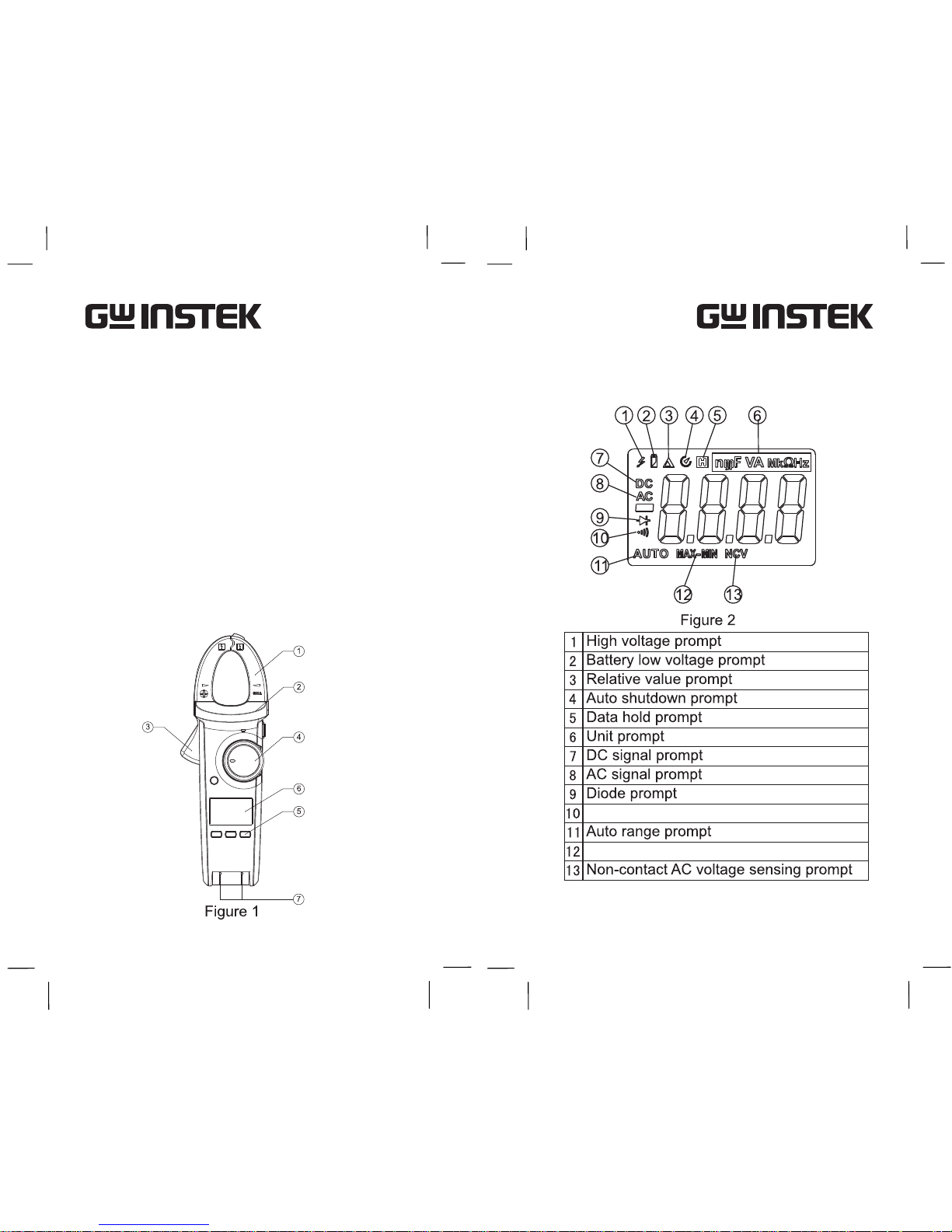
8. When the LCD display shows the icon, “ ”, it
indicates that the battery should be replaced to
ensure the measurement accuracy. Take out the
battery from the clamp meter when the meter
has not been used for a long time.
9. Refrain from altering the internal wiring of the
clamp meter to prevent damage to the meter or
harm to the operator.
10.Refrain from storing or using the clamp meter in
the environments with explosive elements,
flammables, high temperatures, high humidity or
strong electromagnetic fields.
11.Clean the clamp meter case with a soft cloth and
neutral detergents. Do not use abrasive
materials or solvents to prevent corroding the
case, damage to the instrument and to prevent
danger to the operator.
GCM-407 User Manual
GCM-407 User Manual
IV. Electrical Symbols
This symbol signifies the product complies with
both USA and Canadian requirements
Complies with EU standards
Danger! High voltage!
AC or DC (Alternating current or direct current)
Diode
Buzzer on-off
DC (Direct current)
AC (Alternating current)
Warning prompt
Ground
Dual insulation
Capacitance
Do not use the clamp meter if the test lead
insulation is damaged, if the case insulation is
damaged, if the LCD is not functioning or if the
clamp meter is not functioning properly.
2. Do not use the clamp meter if the rear cover or
battery cover is not in place. Failure to do so
may cause electric shock.
3. Keep fingers behind the finger guard. Do not
touch any bare wires, conductors, unused input
terminals, or circuits that are being measured
when the clamp meter is in operation.
4. Make sure the function switch is in the correct
position prior to measurement. Do not change
ranges when using the clamp meter to prevent
damaging the meter.
5. Refrain from applying more than DC1000V/
AC750V to the clamp meter to prevent electric
shock to the user and damage to the clamp
meter.
6. Be careful when measuring RMS voltages
greater than 30DCV or 30ACV as electric shock
can occur.
7. Do not measure voltages or current higher than
the allowable input values. Set the function
range switch to the highest range possible if the
magnitude of the measured value is not known.
Before measuring resistors, diodes or continuity
in a circuit, the circuit should be powered down
and all capacitors in the circuit should be
completely discharged or the measurement
results could be inaccurate.
3
4
GCM-407 User Manual
GCM-407 User Manual
Open/Short or Continuity prompt
V. External Construction (See Figure
1)
1. Clamp head: A device used to measure AC
current and convert current into voltage.
2. Clamp body: Designed to safely protect the
operator from touching dangerous areas.
3. Trigger. Press the trigger to open the clamp
head. When the trigger is released the clamp head
closes.
4. Function dial: Selects the measurement function
or range.
5. Function keys: HOLD, MAX/MIN, REL.
6. LCD display area: Displays the measured data
and the function icons.
7. Input Terminals: Input terminals for measure-
ments other than AC current measurement.
VI. LCD Display (See Figure 2)
Max./Min measurement prompt
5
6
 Loading...