


Battery Meter
GBM-3080/3300
USER MANUAL
Rev. 1.02
ISO-9001 CERTIFIED MANUFACTURER

This manual contains proprietary information, which is protected by
copyright. All rights are reserved. No part of this manual may be
photocopied, reproduced or translated to another language without
prior written consent of Good Will company.
The information in this manual was correct at the time of printing.
However, Good Will continues to improve products and reserves the
rights to change specification, equipment, and maintenance
procedures at any time without notice.
Good Will Instrument Co., Ltd.
No. 7-1, Jhongsing Rd., Tucheng Dist., New Taipei City 236, Taiwan.

TABLE OF CONTENTS
Table of Contents
SAFETY INSTRUCTIONS ................................................... 5
GETTING STARTED ......................................................... 11
GBM Series Overview ...................................................... 12
Appearance ..................................................................... 17
Set Up ............................................................................. 20
SETTING UP ................................................................... 24
Setting up the measurement item ................................... 25
Setting up comparator ..................................................... 40
Setting USB disk.............................................................. 44
MEASUREMENT ............................................................. 48
How to enter [MEAS DISPLAY] page ................................ 49
Setting up measurement function ................................... 51
Setting up corresponding measurement range ................ 52
Setting up measurement speed ....................................... 55
DATA LOGGING AND STATISTICS ................................... 56
Data logging function ...................................................... 57
Statistics function ........................................................... 66
SYSTEM CONFIGURATION ............................................. 74
System configuration page .............................................. 75
System info page ............................................................. 86
OTHER FUNCTIONS ....................................................... 88
Offset adjustment by short test ....................................... 89
Short-circuit test ............................................................. 94
Handler Overview ............................................................ 97
3

GBM-3080/3300 User Manual
REMOTE CONTROL ...................................................... 104
Configure Interface ........................................................ 105
COMMAND OVERVIEW ................................................ 118
Command Syntax ........................................................... 119
Command List ............................................................... 123
APPENDIX .................................................................... 177
GBM-3300 Factory Default Settings ............................... 178
Specifications ................................................................ 180
Dimensions ................................................................... 183
Declaration of Conformity ............................................. 184
4
SAFETY INSTRUCTIONS
WARNING
Warning: Identifies conditions or practices that
could result in injury or loss of life.
CAUTION
Caution: Identifies conditions or practices that
could result in damage to the GBM-3000 series
or to other properties.
DANGER High Voltage
Attention Refer to the Manual
Protective Conductor Terminal
Earth (ground) Terminal
SAFETY INSTRUCTIONS
This chapter contains important safety
instructions that you must follow during
operation and storage. Read the following before
any operation to ensure your safety and to keep
the instrument in the best possible condition.
Safety Symbols
These safety symbols may appear in this manual or on the
instrument.
5

GBM-3080/3300 User Manual
Do not dispose electronic equipment as unsorted
municipal waste. Please use a separate collection
facility or contact the supplier from which this
instrument was purchased.
6

SAFETY INSTRUCTIONS
General Guideline
CAUTION
Make sure that the voltage input level does not
exceed DC330V (for GBM-3300).
DC80.8V (for GBM-3080).
AC voltage input is strictly prohibited.
Do not place any heavy object on the
instrument.
Avoid severe impact or rough handling that can
lead to damaging the instrument.
Do not discharge static electricity to the
instrument.
Use only mating connectors, not bare wires, for
the terminals.
Do not perform measurement at the source of a
low-voltage installation or at building
installations (Note below).
Do not disassemble the instrument unless you
are qualified as service personnel.
Remove all test leads before disconnecting the
mains power cord from the socket.
If the equipment is used in a manner not
specified by the manufacturer, the protection
provided by the equipment may be impaired.
The device should be placed in a place where
the plug connected to it can be removed easily.
(Note) EN 61010-1:2010 specifies the measurement categories and
their requirements as follows. The GBM-3000 Series doesn’t fall
under category II, III or IV.
Measurement category IV is for measurement performed at the
source of low-voltage installation.
Measurement category III is for measurement performed in the
building installation.
Measurement category II is for measurement performed on the
circuits directly connected to the low voltage installation.
Safety Guidelines
7

GBM-3080/3300 User Manual
Power Supply
WARNING
AC Input voltage: 100-240 VAC 50/60Hz
The power supply voltage should not fluctuate
more than 10%.
Connect the protective grounding conductor of
the AC power cord to an earth ground, to avoid
electrical shock.
Cleaning the
Instrument
Disconnect the power cord before cleaning.
Use a soft cloth dampened in a solution of mild
detergent and water. Do not spray any liquid.
Do not use chemicals containing harsh material
such as benzene, toluene, xylene, and acetone.
Operation
Environment
Location: Indoor, no direct sunlight, dust free,
almost non-conductive pollution (Note below)
Temperature: 0°C to 40°C
Humidity:
< 30°C: < 80%RH(non-condensing);
30°C~40°C: <70%RH(non-condensing);
>40°C: <50%RH (non-condensing)
Altitude: <2000m
(Note) EN 61010-1:2010 specifies the pollution degrees and their
requirements as follows. The GBM-3000 SERIES falls under degree
2.
Pollution refers to “addition of foreign matter, solid, liquid, or
gaseous (ionized gases), that may produce a reduction of
dielectric strength or surface resistivity”.
Pollution degree 1: No pollution or only dry, non-conductive
pollution occurs. The pollution has no influence.
Pollution degree 2: Normally only non-conductive pollution
occurs. Occasionally, however, a temporary conductivity caused
by condensation must be expected.
Pollution degree 3: Conductive pollution occurs, or dry, non-
conductive pollution occurs which becomes conductive due to
condensation which is expected. In such conditions, equipment
is normally protected against exposure to direct sunlight,
precipitation, and full wind pressure, but neither temperature
nor humidity is controlled.
8

SAFETY INSTRUCTIONS
Storage
environment
Location: Indoor
Temperature: -10°C to 70°C
Humidity: <80%RH(non-condensing)
Disposal
Do not dispose this instrument as unsorted
municipal waste. Please use a separate collection
facility or contact the supplier from which this
instrument was purchased. Please make sure
discarded electrical waste is properly recycled to
reduce environmental impact.
9
GBM-3080/3300 User Manual
Green/ Yellow:
Earth
Blue:
Neutral
Brown:
Live (Phase)
Power cord for the United Kingdom
When using the unit in the United Kingdom, make sure the power
cord meets the following safety instructions.
NOTE: This lead/appliance must only be wired by competent persons
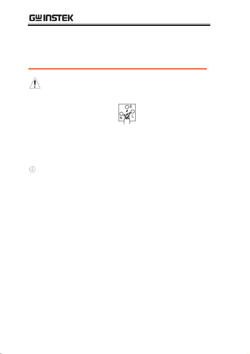
WARNING: THIS APPLIANCE MUST BE EARTHED
IMPORTANT: The wires in this lead are coloured in accordance with the
following code:
As the colours of the wires in main leads may not correspond with
the coloured marking identified in your plug/appliance, proceed
as follows:
The wire which is coloured Green & Yellow must be connected to
the Earth terminal marked with either the letter E, the earth symbol
or coloured Green/Green & Yellow.
The wire which is coloured Blue must be connected to the terminal
which is marked with the letter N or coloured Blue or Black.
The wire which is coloured Brown must be connected to the
terminal marked with the letter L or P or coloured Brown or Red.
If in doubt, consult the instructions provided with the equipment
or contact the supplier.
This cable/appliance should be protected by a suitably rated and
approved HBC mains fuse: refer to the rating information on the
equipment and/or user instructions for details. As a guide, a cable
of 0.75mm2 should be protected by a 3A or 5A fuse. Larger
conductors would normally require 13A types, depending on the
connection method used.
Any exposed wiring from a cable, plug or connection that is
engaged in a live socket is extremely hazardous. If a cable or plug is
deemed hazardous, turn off the mains power and remove the cable,
any fuses and fuse assemblies. All hazardous wiring must be
immediately destroyed and replaced in accordance to the above
standard.
10
GETTING STARTED
GBM Series Overview ...................................................... 12
Series lineup ...................................................................... 12
Characteristics ................................................................... 12
Accessories ........................................................................ 15
Package Contents .............................................................. 16
Appearance ..................................................................... 17
Front Panel ........................................................................ 17
Rear Panel .......................................................................... 19
Set Up ............................................................................. 20
Tilting the Stand ................................................................ 20
Power UP ........................................................................... 22
Connect to the test terminal ............................................. 22
GETTING STARTED
This chapter describes the GBM-3000 SERIES in a
nutshell, including accessories, package contents,
its main features and front / rear panel
introduction.
11

GBM-3080/3300 User Manual
Model name
Basic accuracy
Test speed
Interface
GBM-3080/3300
Resistance: 0.5%
Voltage: 0.01%
60 times/s
RS-232/USB
Handler
Model name
Measurement range
GBM-3080
Resistance: 0. 0001mΩ~3.2kΩ; Voltage: 0.00001~80.000V
GBM-3300
Resistance: 0. 0001mΩ~3.2kΩ; Voltage: 0.00001~300.000V
GBM Series Overview
Series lineup
The GBM-3000 series consists of 2 models as list below.
Characteristics
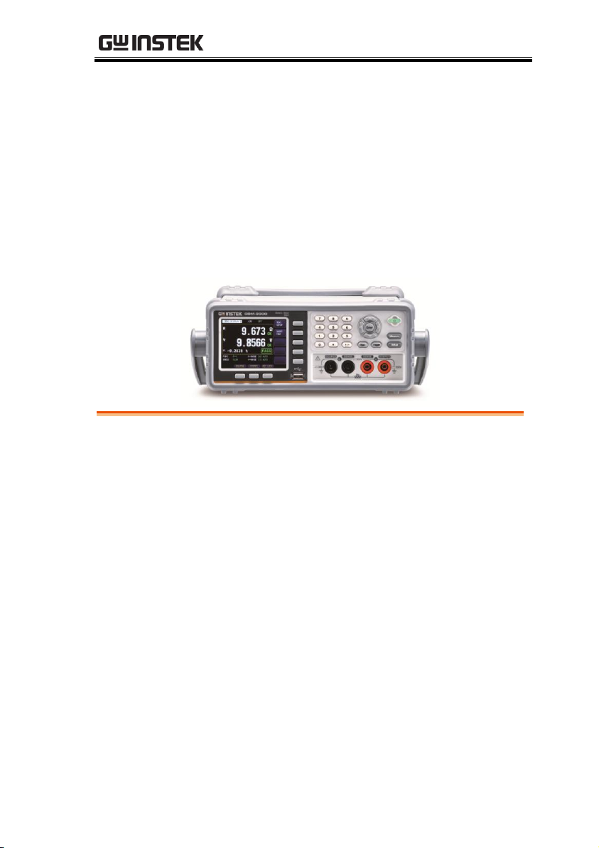
Thank you for purchasing the GBM-3300/ GBM-3080 battery meter.
The GBM-3000 series uses 32-bit ARM microprocessor control and
3.5-inch true color LCD display.
It can be used to test resistance ranging from 0.0001mΩ to 3.2kΩ
and test DC voltage ranging from 0.00001V to 300.000V. The GBM3000 series has several characteristics such as high accuracy, high
resolution and ultra-high speed measurement with 0.5% resistance
accuracy and 0.01% voltage accuracy and up to measurement speed
of 60 times per second.
Comparator function and Handler (PLC) interface can be used to
output HIGH/ IN/ LOW resistance signal and HIGH/ IN/ LOW
voltage signal. It can meet the require of automatic sorting system
to complete the fully automated assembly line test, while enhance
IO signal to drive power relays and signal relays directly.
The built-in RS-232C interface and USB interface can be used for
remote control and data acquisition and analysis.
12

GETTING STARTED
Performance
1kHz test frequency
Basic accuracy for resistance: 0.5%
Basic accuracy for voltage: 0.01%
Features
7 ranges for test, range from 3mΩ to 3kΩ,
including auto, manual and nominal range
mode. Nominal range mode: The instrument
automatically selects the best range based on the
nominal value.
4 test speeds are available for selection.
Including slow, medium, fast and exfast test.
When all channels opened and measurement in
manual mode. 4 times per second for slow
speed mode; 11 times per second for medium
speed mode; 25 times per second for fast speed
mode; 60 times per second for exfast mode.
2 trigger modes, including internal and external.
Calibration function
Short circuit clearing for full ranges is to
eliminate the influence of lead resistance.
System configuration, including data retention
function, alarm setting, keyboard lock function
and administrator and user accounts which
allows to set a password for administrator
Comparator function (Sorting function),
including RHI/RNG/RLO output,
VHI/VNG/VLO output and total NG/OK
output.
Comparison method:
Absolute tolerance ± TOL sorting: The absolute
deviation of the measured value from the
nominal value is compared with the limit of
each range.
The new improved design of AC resistance test principle can be
used for almost all battery internal resistance test, including lithium
batteries, lead-acid batteries, button batteries and other batteries.
13

GBM-3080/3300 User Manual
Percent tolerance %TOL sorting: The percentage
deviation of the measured value from the
nominal value is compared with the limit of
each range.
Sequential sorting: The measured value is
directly compared with the upper and lower
limits setting.
Interface
RS-232 / USB remote control:
Support up to maximum 115200bps serial
transmission rate, compatible SCPI agreement
and ASCII transmission.
Handler I/O interface
All isolation with opt coupler. It equipped with
built-in input and output port to pull up
resistance.
Input: Trigger signal.
Output: All result signal after sorting
comparison, measuring synchronization signal
(EOC) and high current drive output which
directly drives relay.
14

Accessories
Standard Accessories
Part number
Description
82BM-01000E01
User Manual CD
82BM-01000M01
Safety Instruction Sheet
Region dependent
Power Cord
GBM-01
Test Fixture(Kelvin Clip)
Optional Accessories
Part number
Description
GBM-02
Test Fixture(Single Needle)
GBM-03
Test Fixture(Twin Needle)
GBM-S1
Short Board
GTL-232
RS232C cable
GTL-246
USB cable
GRA-422
Rack Adapter Panel (19”, 2U)
GETTING STARTED
15
GBM-3080/3300 User Manual
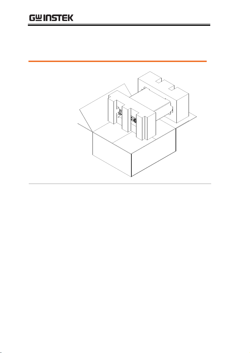
Opening the
box
Contents
(single unit)
Main unit
Test Fixture (Kelvin
Clip)
Power cord x1 (region
dependent)
User manual CD
Safety instruction sheet
Package Contents
Check the contents before using the instrument.
16
Appearance
10 79 8 6
5
4
321
1112
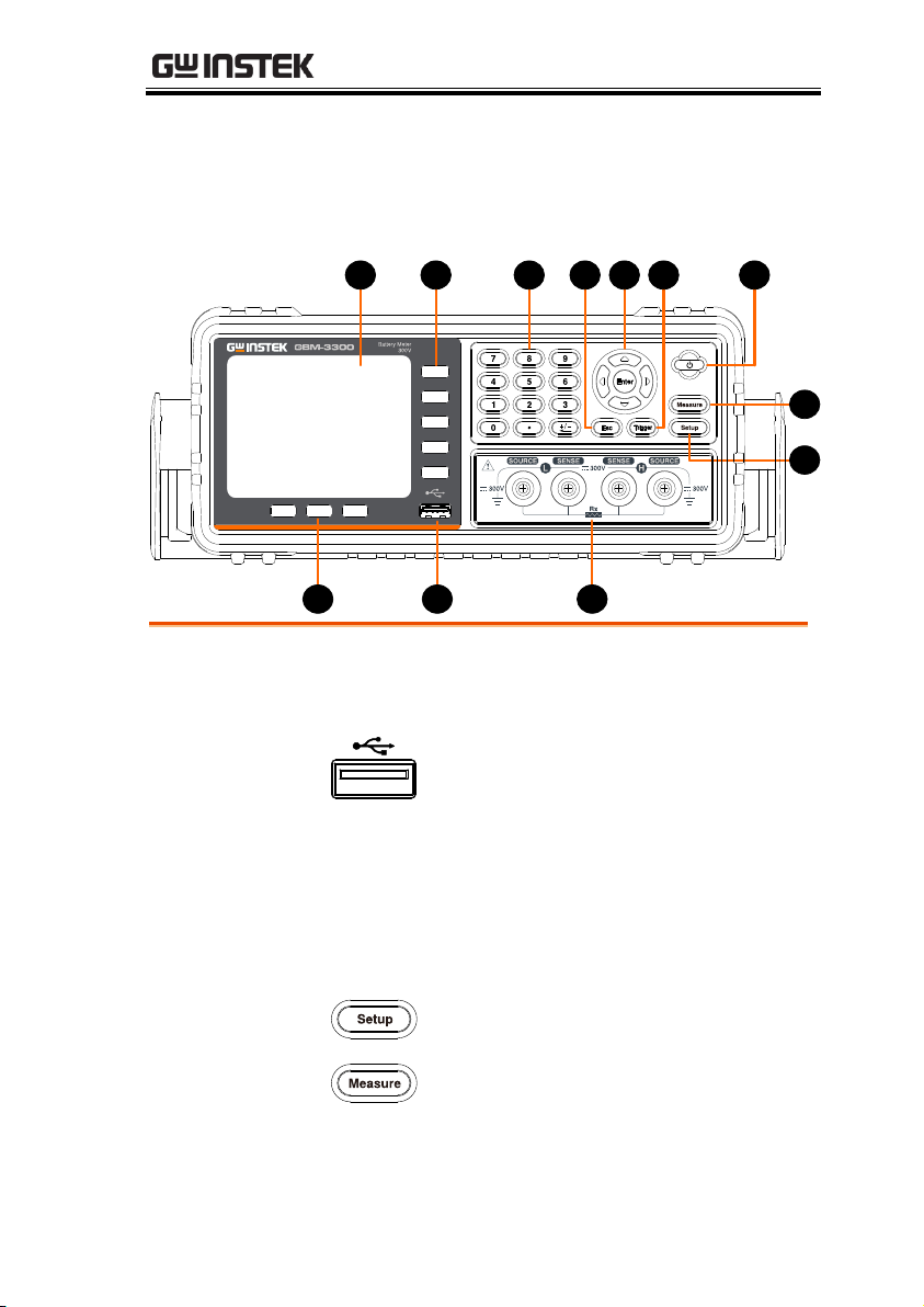
1
Function keys
These three keys are used for entering
system configuration page, activating
enlarge and lock key function.
2
USB port
The Host port is a type A USB port for
logging data and connecting USB
memory devices only.
USB disk type: Flash drive only
Format: FAT/FAT32/exFAT
Max memory size: 128GB.
3
Test
terminals
Test terminals are used to connect test
fixture.
4
Setup key
This key is used for entering
measurement setup page.
5
Measure key
This key is used for entering
measurement display page.
Front Panel
GETTING STARTED
17
GBM-3080/3300 User Manual
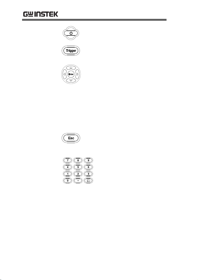
6
Power switch
This key is used to turn the device
instrument on/off. On = light green,
Off = light red.
7
Trigger key
If trigger mode is set to external, this
key can be used to measure trigger.
Please refer to page 30 for details.
8
Arrow Keys
and Enter key
The arrow keys are used to navigate
the cursor on the screen.
Enter key is used to confirm the value
which input from the numeric keypad.
When a flash drive is inserted from the
USB port on the front panel. A
message “USB disk ready Press
<Enter> to save screen” appears on the
lower part of the LCD screen. At this
moment, Enter key can be used to take
a screenshot.
9
ESC key
Press this button to return the cursor
to the top left corner of the currently
displayed page or cancel current
setting.
10
Numeric keys
The numeric keypad is used to
input values for setting.
11
Option keys
Soft keys for use to select
corresponding option which located
on the right of the LCD screen.
12
LCD
3.5” TFT- LCD display.
18
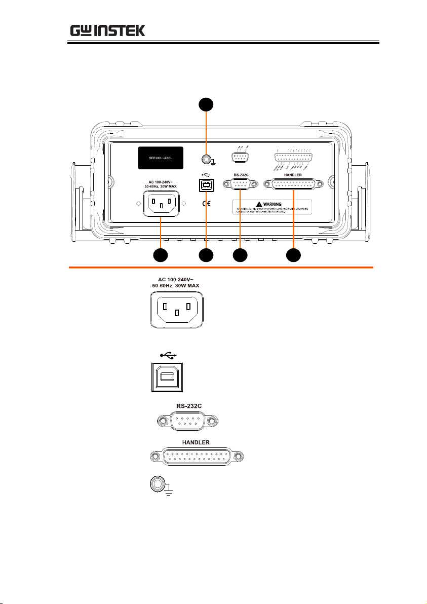
Rear Panel
O
_
RLO
O
_
ROK
O
_
RHI
O
_
VLO
O
_
VOK
O
_
VHI
O
_
RNG
O
_
VNG
O
_
OK
I
_
SELF
_
CAL
321 4
5
1
Power Cord
Socket
Power Socket:
100~240V, 50/60Hz, 10W.
2
USB Device
Port
Type B USB port. This port is used for
remote control.
3
RS232
RS 232 port
4
Handler
interface
Handler I/O port
5
Frame
terminal
This terminal is used for grounding.
GETTING STARTED
19
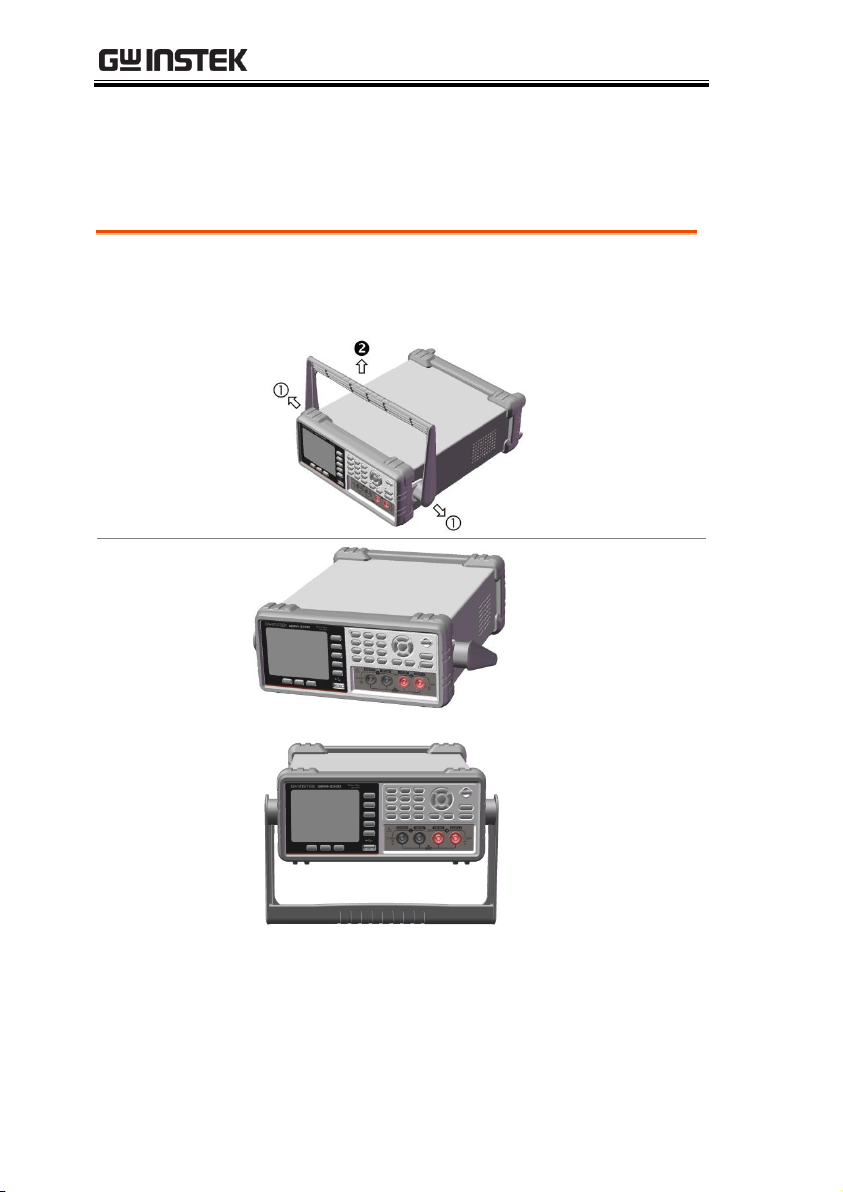
GBM-3080/3300 User Manual
From the base of the handle, gently pull the handle out sideways
and then rotate it to one of the following positions.
Horizontal
position
Tilt stand
position
Set Up
Tilting the Stand
20

GETTING STARTED
Carry position
21
GBM-3080/3300 User Manual
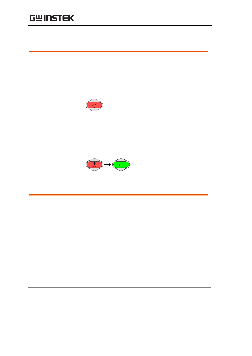
Steps
1. Insert the AC power cord into the power
socket.
2. The power button will be lit red to indicate
that the GBM-3000 series is in standby mode.
3. Press the power button to turn the GBM-3000
series on.
4. The power button will turn green and the
GBM-3000 series will start to boot up.
Background
Please use the "GBM-01" test cable which
comes with the device to connect to the test
terminal for testing. Please follow the
procedure list below to connect.
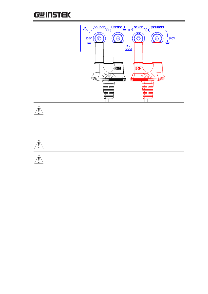
Steps
Please insert correctly the test cable to “Sense”
and “Source” terminals of the device. Insert
the red cable ends to terminals that marked in
H (positive) and the black cable ends to
terminals that marked in L(Negative) as
shown in diagram below.
Power UP
Connect to the test terminal
22
GETTING STARTED
Connection
diagram
Note
Avoid wrong connection, which would lead to
incorrect reading value.
In order to ensure the accuracy of the instrument,
please use the GBM-3000 optional accessories test
cable for test.
Warning
Do not connect the AC current source and voltage
source directly to the test terminals.
Warning
Before connecting the test leads, make sure the test
leads are not connected to any batteries to avoid
personal injury or damage to the instrument.
23

GBM-3080/3300 User Manual
Setting up the measurement item ...................................25
Setting measurement function and corresponding
range ................................................................................. 26
Setting measurement speed ............................................. 29
Setting trigger mode ......................................................... 30
Setting average measurement frequency(AVG) ............... 32
Setting delay timer ............................................................ 33
Setting self-calibration function ....................................... 34
Setting the output current mode ...................................... 36
Setting up monitor parameter and nominal value .......... 37
Setting edge ...................................................................... 39
Setting up comparator .....................................................40
Setting USB disk ..............................................................44
SETTING UP
In this chapter you will learn about all the
measurement-related settings. All the
measurement setting items can be found on
the [MEAS SETUP] page.
24

SETTING UP
Setting up the measurement item
You can set up the following measurement items form the [MEAS
SETUP] page. While on the [MEAS SETUP] page, the device is still
testing although the device doesn’t display the test result.
Setting measurement function and its range→ from page 26
Setting measurement speed → from page 29
Setting trigger mode→ from page 30
Setting measurement frequency→ from page 32
Setting delay timer→ from page 33
Setting self-calibration → from page 34
Setting output current mode → from page 36
Setting monitoring parameter→ from page 37
Setting edge→ from page 39
25
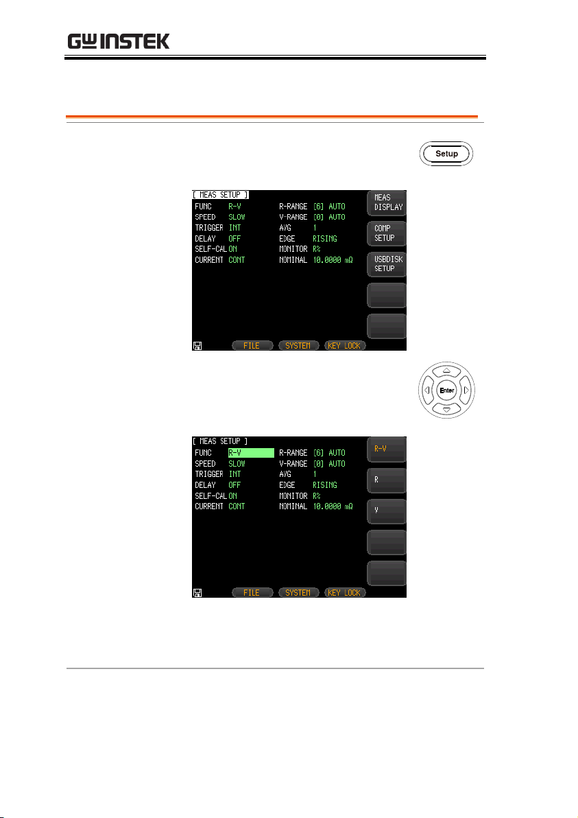
Steps
1. Press the Setup button to enter
[MEAS SETUP] page.
2. Use arrow keys to move the cursor
and select FUNC item on the
[MEAS SETUP] page.
3. Use option key on the right of the LCD screen
to select a parameter for this measurement
item.
Parameter
R-V
Measure and display both the resistance and
voltage of battery under test.
GBM-3080/3300 User Manual
Setting measurement function and corresponding range
26
SETTING UP
R
Measure and display the resistance of battery
under test.
V
Measure and display the voltage of battery
under test.
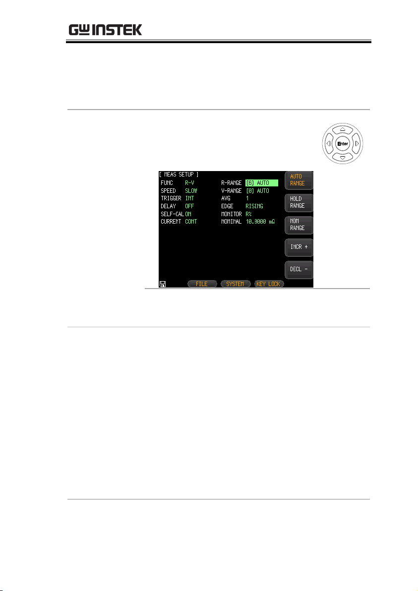
Set measurement
range
4. Use arrow keys to move the cursor
to corresponding measurement
range.
5. Use option key on the right of the LCD screen
to select a desired measurement range.
Measurement
range
AUTO RANGE
The device will automatically select
the best range to test.
HOLD RANGE
The device will always performe test
with a user-specified range.
NOM RANGE
The device will automatically select
the best range to test based on the
nominal value.
INCR+
Increase the range number and set to
hold range.
DECL-
Decrease the range number and set to
hold range.
27

GBM-3080/3300 User Manual
Note
Among the measurement items, the FUNC, RANGE
and SPEED measurement items can also be set from
[MEAS DISPLAY] page. Please refer to page 51 for
details about setting these setting items.
28

SETTING UP
Test Speed
Slow
4 times/sec (250ms)
Medium
11 times/sec (91ms)
Fast
25 times/sec (40ms)
Exfast
60 times/sec (16.6ms)
Steps
1. Press the Setup button to enter
[MEAS SETUP] page.
2. Use arrow keys to move cursor and
select SPEED item on the [MEAS
SETUP] page.
3. Use option key on the right of the LCD screen
to select a test speed for this measurement
item.
Setting measurement speed
The GBM-3300/3080 offers 4 test speeds (Slow, Medium, Fast and
Exfast). The slower the test, the more accurate and stable the test
result.
In the R-V function and manual range mode, the response and
sampling time for enabling the comparator is as follows:
29
GBM-3080/3300 User Manual
Available test
speed
Slow
4 times/sec
Medium
11 times/sec
Fast
25 times/sec
Exfast
60 times/sec
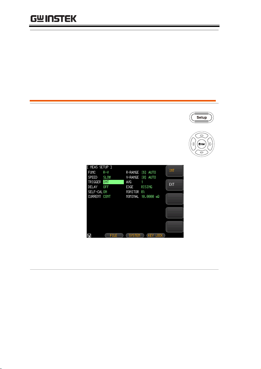
Steps
1. Press the Setup button to enter
[MEAS SETUP] page.
2. Use arrow keys to move cursor and
select TRIGGER item on the
[MEAS SETUP] page.
3. Use option key on the right of the LCD screen
to select a trigger mode for this measurement
item.
Available
parameter
INT
Internal trigger mode is also known as
continuous test. The trigger signal performs
continuous test in accordance with the original
cycle of the device.
EXT
External trigger mode, including
Manual/Handler/Remote control mode.
Manual trigger mode: The device performs
Setting trigger mode
30
 Loading...