

Page 1
GAD-201G user manual
GAD-201G user manual
TABLE OF CONTENTS PAGE
1. PRODUCTION INTRODUCTION.............................1
2. SPECIFICATIONS........................................................2
3. PRECAUTIONS BEFORE OPERATION..................4
4. PANEL INTRODUCTION...........................................6
5. OPERATING INSTRUCTIONS................................11
6. MAINTENANCE.........................................................14
6-1. Line fuse replacement..........................................14
6-2. Cleaning.................................................................14
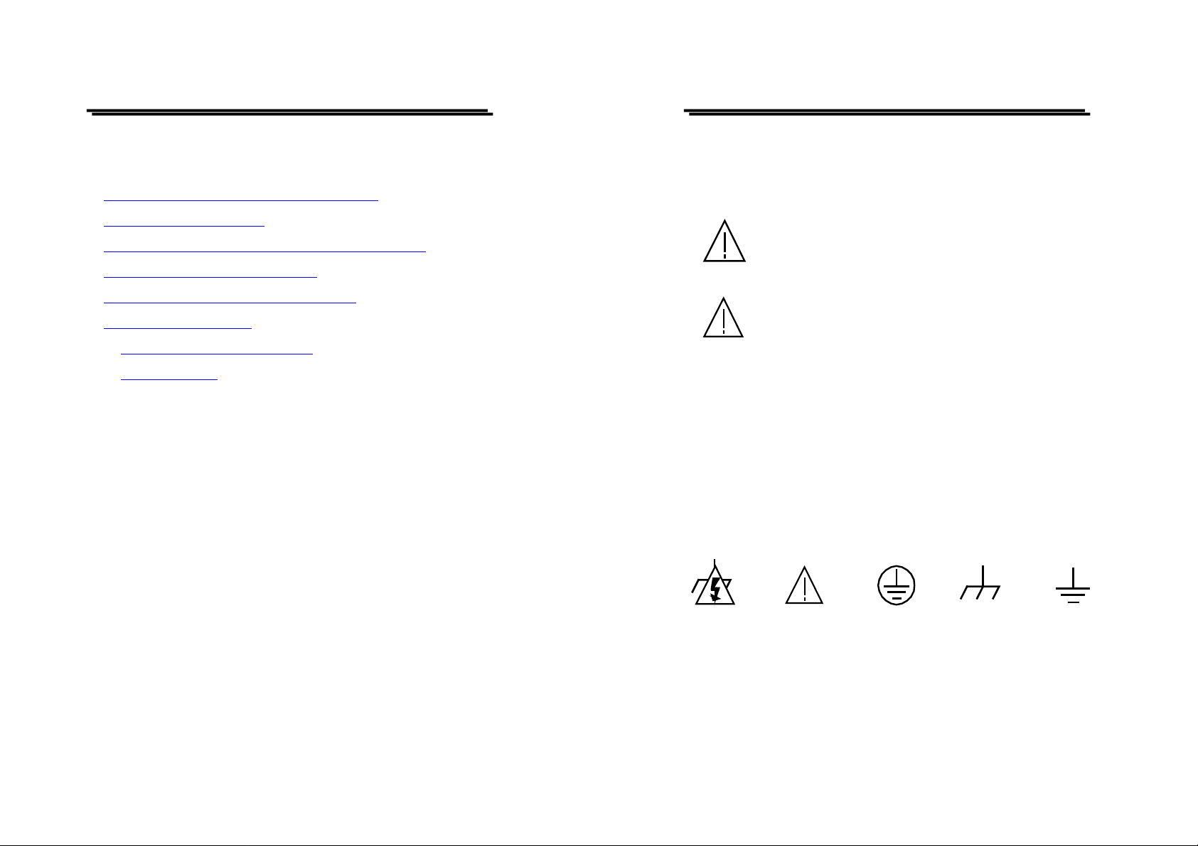
SAFETY TERMS AND SYMBOLS
These terms may appear in this manual or on the product:
WARNING: Warning statements identify condition or
practices that could result in injury or loss life.
CAUTION: Caution statements identify condition or
practices that could result in damage to this product or
other property.
Measurement category I is for measurements performed on circuits not
directly connected to MAINS.
Measurement category II is for measurements performed on circuits
directly connected to the low voltage installation.
Measurement category III is for measurements performed in the
building installation.
Measurement category IV is for measurements performed at the source
of the low-voltage installation.
DANGER
High
Voltage
i
ATTENTION
Refer to
Manual
Protective
Conductor
terminal
ii
Frame or
Chassis
Terminal
Earth
(ground)
Terminal
Page 2
GAD-201G user manual
GAD-201G user manual
1. PRODUCTION INTRODUCTION
The model GAD-201G Automatic Distortion Meter is designed to
measure the total distortion down to 0.1% full scale at any frequency
between 20Hz and 20kHz.
The instrument provides the function of automatic tuning, auto ranging
and automatic level control circuit to save the time of adjustment,
frequency tuning control and input level setting control.
The instrument uses two meters allowing simultaneous level and
distortion measurements. The range selection for both distortion and level
measurements is automatically made with a reed relay.
The instrument also equips with a frequency holding selector to keep a
spot frequency in a suitable condition to measure distortion factor of audio
equipment, such as FM/AM radios, stereo amplifiers, tape recorders,…etc.
Besides, the instrument uses X axis and Y axis two outputs to observe
the waveforms of the input signal and the total harmonics. All these
features allow an easy measurement of Lissajous’ figure distortion and the
analysis of distortion accuracy.
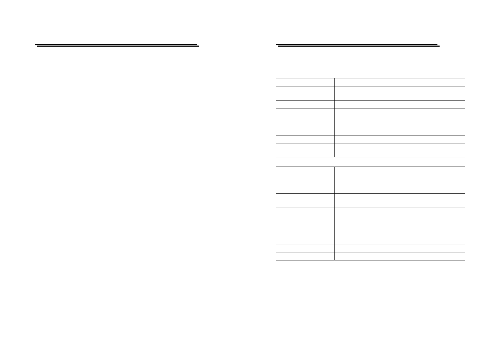
2. SPECIFICATIONS
Distortion Measurements
Measure Range 0.1% to 10% full scale in 7 ranges by auto ranging
Fundamental Frequency
range
Input level 100mVrms to 300Vrms
Fundamental Harmonic
Rejection Ratio
Secondary Harmonic
Accuracy
Residual Distortion Less than 0.03% (including hum and noise)
Maximum Input
Voltage
AC Voltage Measurements
Level measurement on
AC voltage ranges
Decibel range
Decibel scale -20dB to +1dB (0dB=1V)
Accuracy
Frequency response
Residual noise
Input impedance
20Hz to 20kHz 3 ranges continuous fine adjustme nt ,
3 spot frequency: 400Hz, 1kHz, and 10kHz±1% only
80dB above
Within ±1dB at a basic frequency of 20Hz to 20kHz.
DC +AC peak, 400V or less
1mVrms to 300Vrms full scale in 12 ranges by auto
ranges
-60dB to +50dB in increments of 10dB
-60dBm to +50dBm in increments of 10dBm
-20dBm to +3.2dBm (0dBm=1mW, 600Ω)
Within ±3% of full scale (at 1kHz)
Within ±0.5dB, 20Hz to 200kHz for 100mV to 300mV
ranges
Within ±1dBm, 20Hz to 200kHz for 1mV to 30mV
ranges
Less than 10μV with input short circuit
100kΩ±10%, 70pF or less (unbalance)
1
2
Page 3
GAD-201G user manual
GAD-201G user manual
X Output:
Approx. 1Vrms at full scale in measuring input level
Output terminal
Output impedance
Power source 100/120/220/240V, 50/60Hz, 25VA, 10Watts
Stability against line
voltage fluctuation:
Dimensions 310 (W) × 165(H) × 265(D) mm
Weight Approx. 4.6 kg
Accessories
Operation Environment
WARNING: To avoid electrical shock, the power cord
protective grounding conductor must be connected to
ground.
CAUTION: To avoid damaging the instrument, don’t use
it in a place where ambient temperature exceeds +50℃.
Y Output:
Approx. 500mVrms at full scale in measuring distortion
Factor (total harmonic signal output)
Approx. 600Ω
The indication of line voltage fluctuation is changed to
±10%, within ±0.5% of full scale.
Test leads GTL-103 × 1
User Manual × 1
Indoor use
Altitude up to 2000m
Installation category II
Pollution Degree 2
3. PRECAUTIONS BEFORE OPERATION
Unpacking the instrument
The product has been fully inspected and tested before shipping from the
factory. Upon receiving the instrument, please unpack and inspect it to
check if there is any damage caused during transportation. If any sign of
damage is found, notify the bearer and/or the dealer immediately.
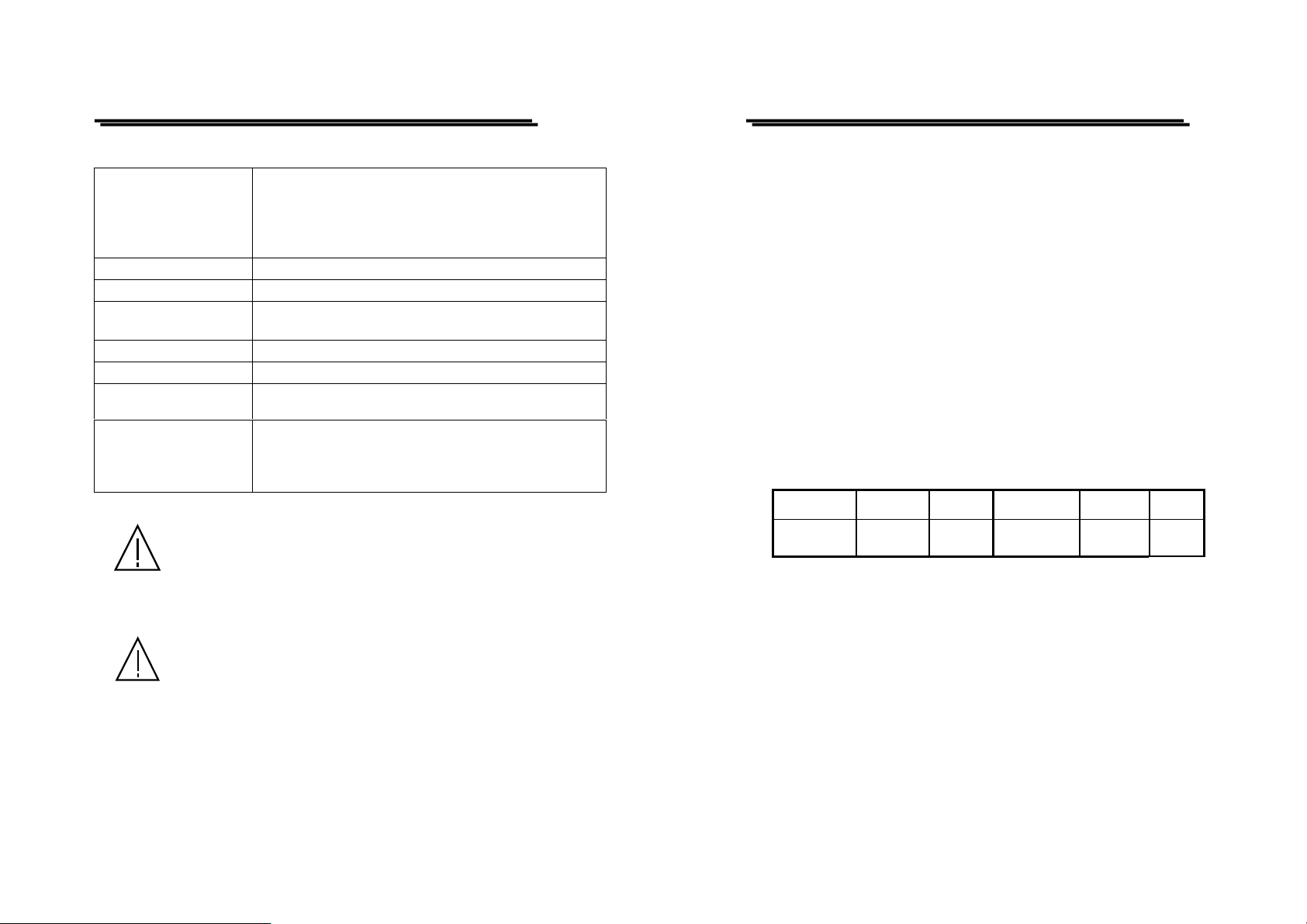
Checking the Line Voltage
The instruments can be applied with any kind of line voltage shown in
the table below. Before connecting the power plug to an AC line outlet,
make sure the voltage selector of the rear panel is set to the correct
position corresponding to the line voltage. It might be damaged the
instrument if connected to the wrong AC line voltage.
When line voltages are changed, replace the required fuses shown as
below:
Line voltage Range Fuse Line voltage Range Fuse
100V
120V
Maximum input voltage
Any input voltage over the maximum specific voltage can damage the
instrument. The specific voltage is determined by how much the peak
value of the input signal is adding plus the superimposed DC voltage.
90-110V
108-132V
T 0.3A
250V
220V
240V
198-242V
216-264V
T0.2A
250V
3
4
Page 4

GAD-201G user manual
GAD-201G user manual
Full Scale
The instrument uses a special extended scale with the reading range
larger than the conventional full scale:
Conventional Extended
0 to 1.0 0 to 1.12
0 to 3.1(3.2) 0 to 3.5
-20 to 0dB -20 to +1dB
-20 to +2dBm -20 to +3.2dBm
The rated value of full scale expressed in term of 1.0 on the 0~1.12 scales.
Set the pointer to “1.0” on the outermost scale.
WARNING. Avoid applying any external signal to the X-Y
output terminal to prevent the Distortion Meter from
damage.
The equipment shall not be used for measurements within
category I, II, III and IV.
WARNING. To avoid personal injury, disconnect the
power cord before removing the fuse holder.
4. PANEL INTRODUCTION
z Front Panel
5
6
Page 5
GAD-201G user manual
GAD-201G user manual
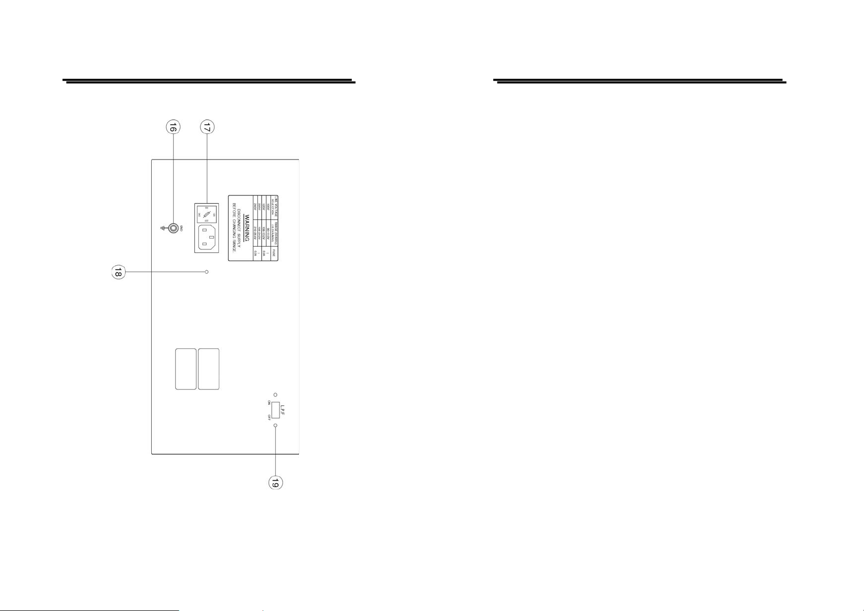
z Rear Panel
(1) INPUT terminal
The terminal is used commonly for the measurements of distortion
factor and AC voltage.
(2) AUTO and HOLD function control
The pushbutton is used for automatic measurement or holding the
desired range during testing.
(3) Function and Frequency range selector
The selectors are used to set a basic frequency range of distortion
factor. Simultaneously use the frequency knob referring to (15) to
set a basic frequency range, then, press the spot button and one of
three buttons to select a desired spot frequency.
(4) X-output terminal
A binding post terminal is used for observing signal waveforms.
Connect the terminal to the “X” input of oscilloscope to observe
Lissajous’s figure. The full scale position of output voltage is about
1V rms.
(5) GND output terminal
Ground the terminal when the X and Y output is used.
(6) Y-output terminal
The terminal is used to observe signal waveforms, which is used as a
total harmonic signal output during distortion measurement.
Connect the terminal to the “Y” input of oscilloscope to observe
Lissajous’s figure. The full scale position of output voltage is about
0.5V rms.
7
8
Page 6

GAD-201G user manual
GAD-201G user manual
(7) Power switch
Push the switch to left, and the pilot lamps corresponding to the
measuring range will light up to indicate that the distortion meter is
energized and ready for operation.
(8) Measuring range pilot lamps
Pilot lamps corresponding to the scale stage will light up according
to the voltage level and distortion factor of the input signal.
(9) LEVEL zero adjustment
This is for mechanical zero adjustment of Level pointer.
(10) DISTORTION zero adjustment
This is for mechanical zero adjustment of Distortion pointer.
(11) LEVEL meter
The meter is to detect mean values, calibrate sinewave input and
indicate effective values. Its scale stages are 0~1.12, 0~3.5,
-20~+1dB, and -20~+3.2dBm.
(12) DISTORTION meter
The scale stages are 0~1.12%, 0~3.5%, and -20~+1dB.
(15) TUNING FREQ. setting knob
The knob is used to adjust the frequency to a desired value.
(16) Power Cord
Connect the power cord to a suitable AC source.
(17) Fuse holder
For circuit protection.
(18) GROUND terminal
The terminal is connected to both the cabinet and signal input
grounding.
(19) L.P.F.(Low Pass Filter) switch
This slide switch can select “Low Pass Filter” function which is at
3dB of 100kHz nominally.
(13) HIGH pilot lamp (tuning Frequency)
The lamp lights when the center frequency of the basic signal
rejection filter is lower than the basic input frequency.
(14) LOW pilot lamp (TUNING FREQ.)
The lamp lights when the center frequency of the basic signal
rejection filter is higher than the basic input frequency.
9
10
Page 7

GAD-201G user manual
GAD-201G user manual
5. OPERATING INSTRUCTIONS
1) Power on
a. Set the POWER switch to “OFF” position.
b. Check zero setting—If offset, adjust the pointer to zero by using
a small screwdriver.
c. Set the POWER switch to “ON” position.
2) Before applying an inpu t sign al
The instrument would be damaged by any applied signal which has an
excessive input voltage larger than 350Vrms. Make sure the input
voltage of the signal is less than 350Vrms.
3) AC voltage measurement
a. The range will be selected automatically when a signal is
connected to the input terminal, and the corresponding pilot
lamps are lighting on.
b. The reading value is obtained above one third of scale of meter
at least.
4) The decibel scale
The numerals under the pilot lamps correspond to the decibel (dB)
scale that ranges from 0 to +50dB. The decibel numerals correspond
to the voltage scale that ranges from 1V to 300V. If the range indicates
300mV to 1mV, it is necessary to add -60dB to the mentioned decibel
value.
5) Distortion measurement
In order to reject the fundamental harmonics, the distortion meter is
required the adjustment of the notch filter frequency. The instrument
provides Automatic Level Control (ALC) and automatic
synchronization, but it is required to adjust the frequency for
continuous measuring function.
a. Use FREQUENCY RANGE selector to set the input basic
fundamental frequency range to :
× 1
………………20Hz to 200Hz
× 10
…………… 200Hz to 2kHz
× 100
…………. 2kHz to 20kHz
b. Use TUNING FREQ. knob (15), the push buttons “H IGH”(13)
and “LOW”(14) to minimize the reading value of the meter.
c. When the basic frequency of the input signal is equal to the
fundamental frequency, the lamps of the TUNING FREQ. is on.
Turn the knob to the left (the pilot lamp of “HIGH” is on) or to
the right (the pilot lamp of “LOW” is on) to increase or
decrease the fundamental frequency, then turn off two lamps.
d. Connect the oscilloscope to X/Y output terminal, when the
pointer of the meter indicates the full scale position on 100%
range, the Lissajous’ figures can be observe as shown on the
Fig. 3 (a) below.
11
12
Page 8

GAD-201G user manual
Then, adjust (15) TUNING FREQ. knob to obtain the figure as
shown on the Fig. 3 (b) and (c).
(a) (b) (c)
GAD-201G user manual
6. MAINTENANCE
The following instructions should be performed by the qualified
personnel only in order to avoid electrical shock. Do not perform any
servicing other than the operating instructions unless you are qualified to
do so.
6-1. Line fuse replacement
If the fuse is blown, the instrument would not work. Try to determine
Fig. 3
and correct the cause of the blown fuse. The input power fuse is
located within the instrument in a fuse clip. When replacement is
required, install (T0.3A 100V/120V), (T0.2A, 220V/240V) as
indicated on the rear plate.
WARNING: For continued fire protection. Replace fuse
only with the specified type and rating, and disconnect
the power cord before replacing fuse.
6-2. Cleaning
Clean the front panel and case with denatured alcohol o r a mild solution
of detergent and water. Do not use aromatic hydrocarbons or chlorinated
solvents because they will react with the plastic materials of the
instrument.
13
14
 Loading...