

Page 1

Three Phase Power Controller
ASR-002
USER MANUAL
Rev. A
ISO-9001 CERTIFIED MANUFACTURER
Page 2

This manual contains proprietary information, which is protected by
copyright. All rights are reserved. No part of this manual may be
photocopied, reproduced or translated to another language without
prior written consent of Good Will company.
The information in this manual was correct at the time of printing.
However, Good Will continues to improve products and reserves the
rights to change specification, equipment, and maintenance
procedures at any time without notice.
Good Will Instrument Co., Ltd.
No. 7-1, Jhongsing Rd., Tucheng Dist., New Taipei City 236, Taiwan.
Page 3

Table of Contents
Table of Contents
SAFETY INSTRUCTIONS .................................................. 4
GETTING STARTED .......................................................... 7
ASR-002 Overview ................................................... 7
Front Panel .............................................................. 8
Rear Panel ............................................................. 10
OPERATION .................................................................. 11
Basic Operation ..................................................... 12
Advance Setting ..................................................... 14
Phase Angle Setting ............................................... 16
Voltage Ramp Setting ............................................ 17
Frequency Sweep Setting ....................................... 18
Unit Setting Value Display ..................................... 19
Wire Connection & Accessories ............................. 20
APPENDIX ..................................................................... 21
ASR-002 Dimension ............................................... 21
Using the Rack Mount Kit ...................................... 22
Command List ....................................................... 23
ASR-002 Error Messages........................................ 24
3
Page 4
ASR-002 Series User Manual
WARNING
Warning: Identifies conditions or practices that
could result in injury or loss of life.
CAUTION
Caution: Identifies conditions or practices that
could result in damage to the ASR-002 or to other
properties.
DANGER High Voltage
Attention Refer to the Manual
Protective Conductor Terminal
Earth (ground) Terminal
SAFETY INSTRUCTIONS
This chapter contains important safety
instructions that you must follow during
operation and storage. Read the following before
any operation to ensure your safety and to keep
the instrument in the best possible condition.
Safety Symbols
These safety symbols may appear in this manual or on the
instrument.
4
Page 5
SAFETY INSTRUCTIONS
Do not dispose electronic equipment as unsorted
municipal waste. Please use a separate collection
facility or contact the supplier from which this
instrument was purchased.
General
Guideline
CAUTION
Do not place any heavy object on the ASR-002.
Avoid severe impact or rough handling that
leads to damaging the ASR-002.
Do not discharge static electricity to the ASR-
002.
Use only mating connectors, not bare wires, for
the terminals.
Do not block the cooling fan opening.
Do not disassemble the ASR-002 unless you are
qualified.
If the equipment is used in a manner not
specified by the manufacturer, the protection
provided by the equipment may be impaired.
Power Supply
WARNING
AC Input voltage range:
230 Vac ± 15%
Frequency: 50/60 Hz
To avoid electrical shock connect the protective
grounding conductor of the AC power cord to
an earth ground.
Cleaning the ASR002
Disconnect permanently connected power input
before cleaning.
Use a soft cloth dampened in a solution of mild
detergent and water. Do not spray any liquid.
Do not use chemicals containing harsh material
such as benzene, toluene, xylene, and acetone.
Safety Guidelines
5
Page 6
ASR-002 Series User Manual
Operation
Environment
Location: Indoor, no direct sunlight, dust free,
almost non-conductive pollution (Note below)
Relative Humidity: 20%~ 80%, no condensation
Altitude: < 2000m
Temperature: 0°C to 40°C
Storage
environment
Location: Indoor
Temperature: -10°C to 70°C
Relative Humidity: ≤90%, no condensation
Disposal
Do not dispose this instrument as unsorted
municipal waste. Please use a separate collection
facility or contact the supplier from which this
instrument was purchased. Please make sure
discarded electrical waste is properly recycled to
reduce environmental impact.
6
Page 7

GETTING STARTED
ASR-002 Overview .............................................................. 7
Front Panel ......................................................................... 8
Rear Panel ........................................................................ 10
GETTING STARTED
This chapter describes the ASR-002 power
controller in a nutshell, including its main
features and front/rear panel introduction.
ASR-002 Overview
ASR-002, which is a three-phase power controller, is able to controll
up to 3 single phase power supply units (ASR series only).
It effectively makes AC output conformed to 1P3W/3P4W that
generally unit requires, and also turns output into 3P3W via
designated wire method.
When the select single phase power is greater than the capacity of
2kVA, it is suggested that output should be connected to external
terminal for safety consideration.
7
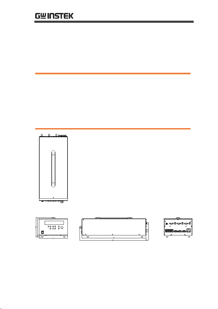
Page 8
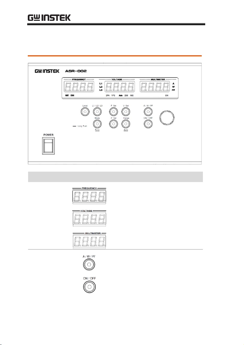
Front Panel
Section
Figure
Description
Header Displays
FREQUENCY: It displays frequency.
VOLTAGE: It displays voltage.
MULTIMETER: It displays A current /
W power / PF power factor.
Function Keys
It changes header display A W
PF.
ON: Output on.
OFF: Output off.
ASR-002 Series User Manual
8
Page 9

GETTING STARTED
V Set: It configures voltage.
Range: It toggles between 100V and 200V.
Auto: It enters Auto range by long press.
F Set: It configures frequency.
P Set: It configures L2 / L3 phase.
L1 / L2/ L3: It changes among L1
L2 L3.
Mode: It toggles between 1P3W 3P4W.
Func: It configures advance setting by
long press.
Local: It cancels connection and
enters the local opeation mode.
Knob Key: It adjusts value by scroll.
Also, it switches input adjustion
position by press.
Display Icons
It indicates remote control mode.
It indicates that error of control occurs.
It indicates output phase.
It indicates output mode.
It indicates output range.
It indicates measurement unit display.
9
Page 10

Rear Panel
Section
Figure
Description
USB Port
USB B-type port for remote control.
RS232C Port
RS232C port for remote control.
SIG OUT
SIG OUT for phase control signal
output.
Phase Terminal
The phase terminals for L1/L2/L3.
Output Terminal
1P3W: Single phase 3 wire.
3P4W: Three phase 4 wire.
Power Voltage
Input
Voltage Input: AC 220V.
Power Frequency: 47 – 63Hz.
ASR-002 Series User Manual
10
Page 11

OPERATION
Basic Operation................................................................ 12
Output Mode Setting Process ..................................................................... 12
Voltage Range Setting Process ................................................................... 12
Voltage Value Setting Process .................................................................... 12
Frequency Setting Process ........................................................................... 13
Phase Shift Setting Process ......................................................................... 13
Advance Setting................................................................ 14
Voltage Amplification Setting Process ...................................................... 14
Slew Reate Setting Process .......................................................................... 14
RS232 Baudrate Setting Process ................................................................. 15
Factory Default Setting Process ................................................................. 15
Phase Angle Setting .......................................................... 16
Phase Angle Setting Process ....................................................................... 16
Voltage Ramp Setting ....................................................... 17
Voltage Ramp Setting Process .................................................................... 17
Frequency Sweep Setting .................................................. 18
Frequency Sweep Setting Process .............................................................. 18
Unit Setting Value Display ................................................ 19
Unit Setting Value Display Setting Process .............................................. 19
Wire Connection & Accessories ........................................ 20
ASR-2000 Series example ............................................................................ 20
Accessories ..................................................................................................... 20
OPERATION
11
Page 12

ASR-002 Series User Manual
Steps
1. Press the Mode key.
2. Toggle between 1P3W 3P4W.
Steps
1. Press the Range key.
2. Toggle between 100V 200V.
Press and hold the Range key to enter Auto.
Steps
1. Press the V Set key.
2. Scroll the Knob key to adjust voltage value.
3. 100V: 0 – 175V
200V: 0 – 350 V
Auto: 0 – 350V
4. After adjustment, press the V Set key again to
upload the set value to ASR series unit.
Basic Operation
Output Mode Setting Process
Voltage Range Setting Process
Voltage Value Setting Process
12
Page 13

OPERATION
Steps
1. Press the F Set key.
2. Scroll the Knob key to adjust frequency value.
3. Frequency range: 40 – 999.9Hz.
Steps
1. Press the P Set key.
2. Scroll the Knob key to adjust phase.
L2 setting range: 85° 155°.
3. Press the P Set key to enter the next step.
L3 setting range: 205° 275°.
4. Press the P Set key to exit.
Frequency Setting Process
Phase Shift Setting Process
13
Page 14

ASR-002 Series User Manual
Steps
1. Press and hold the Mode key to enter the setting.
2. Adjust L1/L2/L3 based on voltage amplification.
3. Scroll the Knob key to
adjust amplification. The
setting range: 0 – 3.5.
Press L1/L2/L3 key to
enter next step.
4. After configuration, press the Range key to enter
the next step.
Steps
1. Slew Rate setting. Setting
range: 0.001 – 0.5.
2. After configuration, press the Range key to enter
the next step.
Advance Setting
Voltage Amplification Setting Process
Slew Reate Setting Process
14
Page 15

OPERATION
Steps
1. RS232 interface
transmittion speed
setting (9600 by default).
Setting range: (9600
19200 38400 57600
115200).
Steps
1. Restore to the factory
default setting. Press the
Range key, and the system
exits automatically.
RS232 Baudrate Setting Process
Factory Default Setting Process
15
Page 16
ASR-002 Series User Manual
Steps
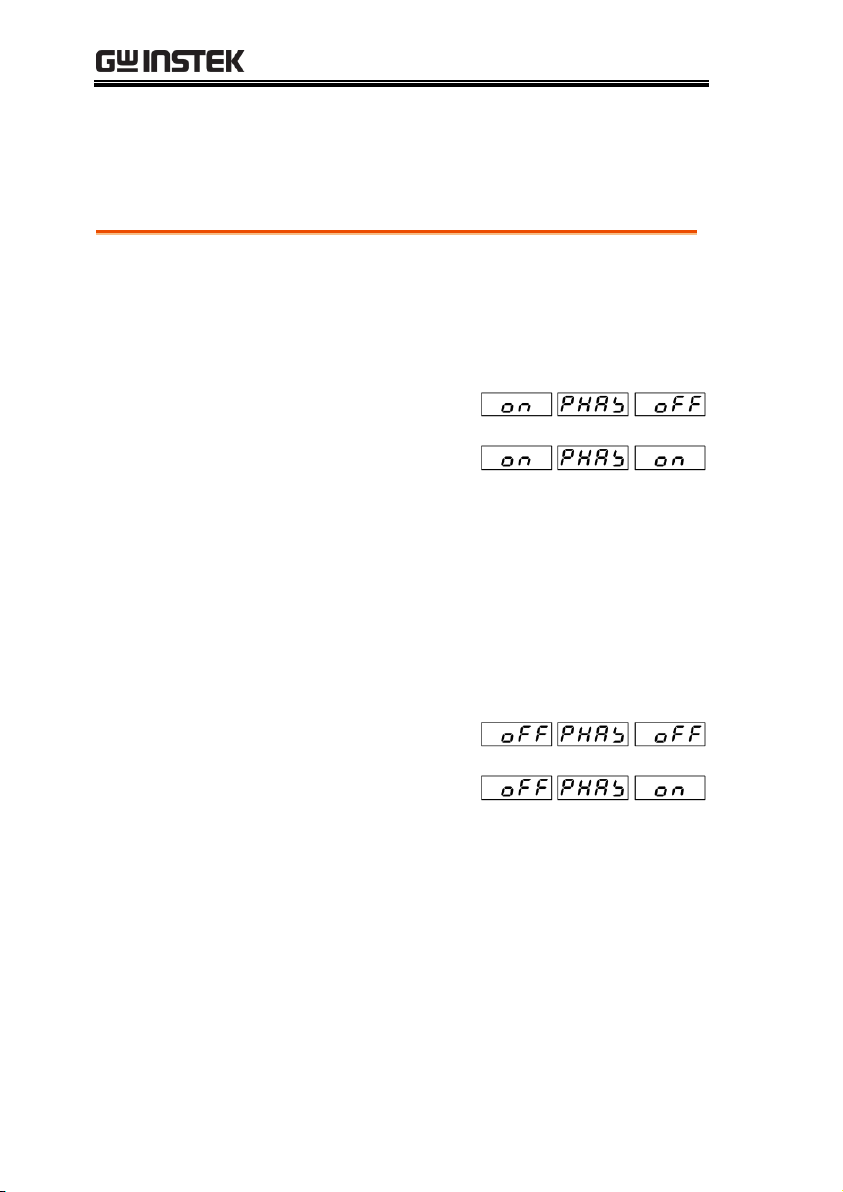
1. Press and hold the P Set key to enter the phase
angle setting.
2. Set the starting angle.
3. The default setting is OFF.
4. Press the Range key to
enter next step or scroll
the Knob key to adjust to
ON for angle setting. The
setting range: 0° - 359°.
5. Press the Range key to enter the next step and exit
from starting angle setting.
6. Set the ending angle.
7. The default setting is OFF.
8. Press the Range key to
finish phase angle setting
or scroll the Knob key to
adjust to ON for angle
setting. The setting
range: 0° - 359°.
9. After configuration, press the Range key to finish
phase angle setting.
Phase Angle Setting
Phase Angle Setting Process
16
Page 17
OPERATION
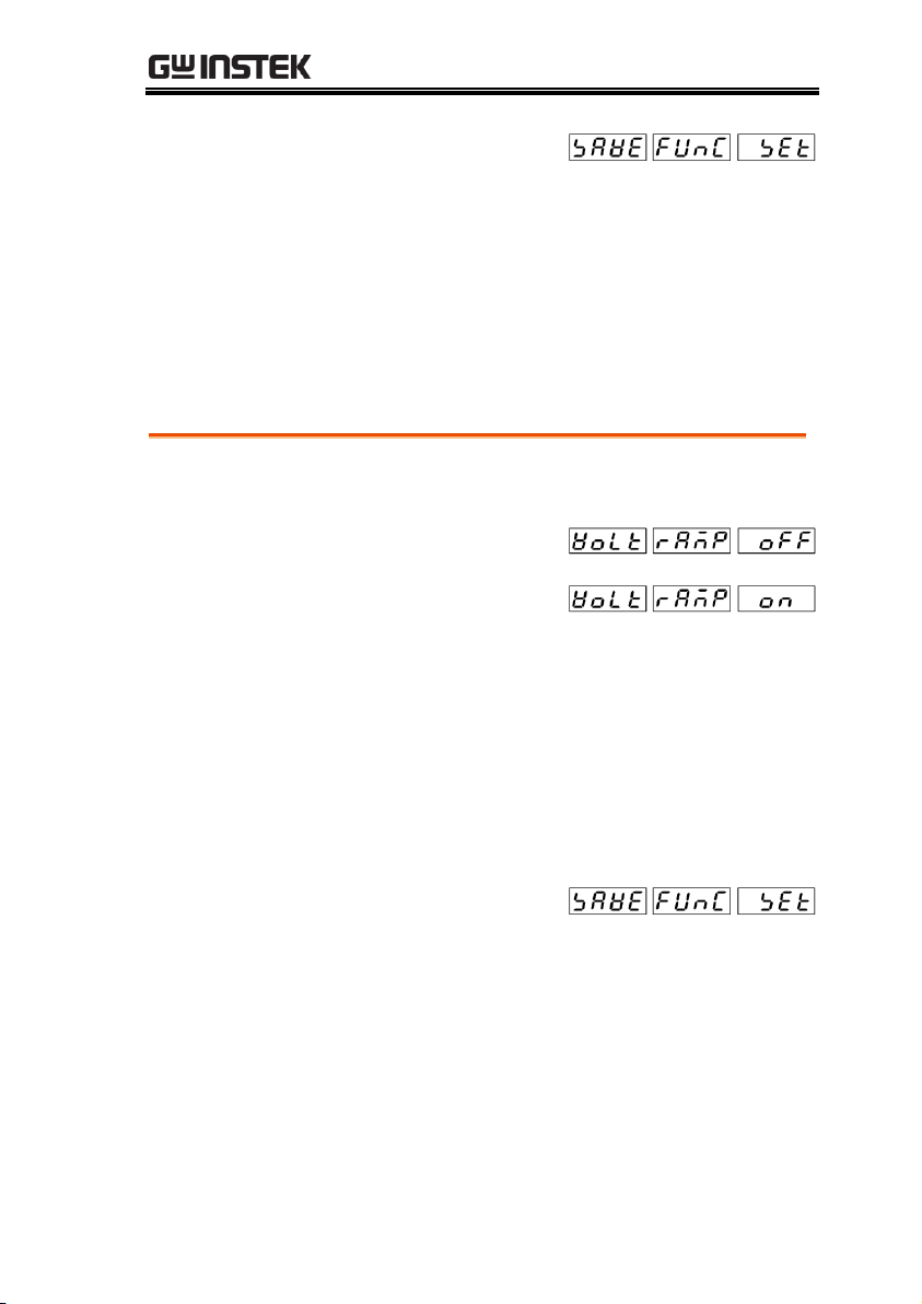
10. Press and hold the Mode
key and display will be
shown as the right figure.
11. Press the Range key to save the setting and exit.
Steps
1. Press and hold the V Set key to enter the Ramp setting.
2. The default setting is OFF.
3. Press the Range key to exit
from Ramp setting or scroll
the Knob key to Ramp ON
followed by pressing
Range key to enter the
Ramp value setting.
4. The setting range: 0.001 – 9.999
5. Press the Range key to exit.
6. Press and hold the Mode
key and display will be
shown as the right figure.
7. Press the Range key to save the setting and exit.
Voltage Ramp Setting
Voltage Ramp Setting Process
17
Page 18
ASR-002 Series User Manual
Steps
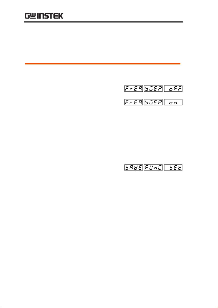
1. Press and hold the F Set key to enter the Sweep setting.
2. The default setting is OFF.
3. Scroll the Knob key to
Sweep ON followed by
pressing the Range key
to enter the Sweep value
setting.
4. The setting range: 0.001 – 9.999
5. Press the Range key to exit.
6. Press and hold the Mode
key and display will be
shown as the right figure.
7. Press the Range key to save the setting and exit.
Frequency Sweep Setting
Frequency Sweep Setting Process
18
Page 19

OPERATION
Steps
1. Press and hold the Mode key to enter the setting.
2. Press the L1/L2/L3 key to browse the default
settings as follows.
L1 Vref 1.000
L2 Vref 1.000
L3 Vref 1.000
SLEW RATE 0.200
BAUD 9600
FACT DEFA
SOFT VER T101
SAVE FUNC SET
EXT ASR SET
EXIT FUNC SET
Unit Setting Value Display
Unit Setting Value Display Setting Process
19
Page 20
ASR-002 Series User Manual
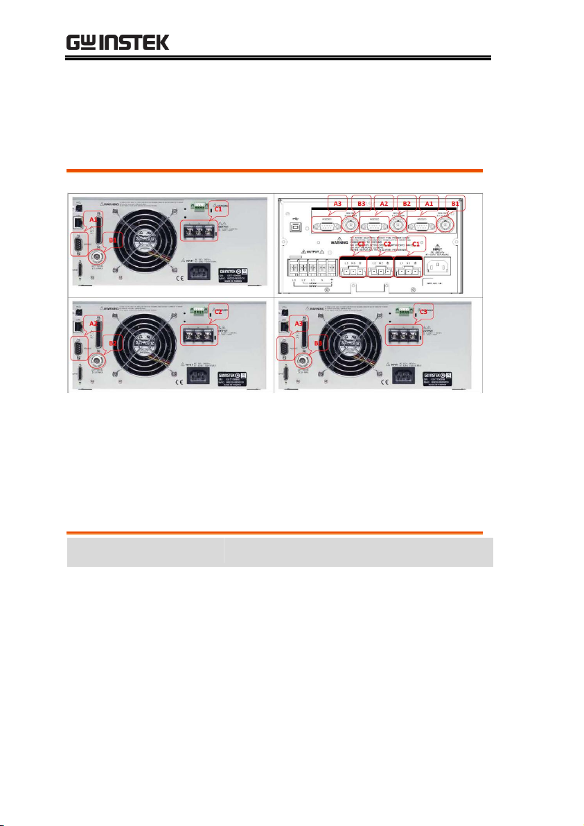
ASR-2100 A1 to ASR-002 A1
B1 to B1
C1 to C1
ASR-2100 A2 to ASR-002 A2
B2 to B2
C2 to C2
ASR-2100 A3 to ASR-002 A3
B3 to B3
C3 to C3
Part Number
Description
GTL-232 x 3
RS232C cable, approx. 2M
GTL-110 x 3
BNC test lead, approx 1.1M
GTL-246 x 1
USB Cable (USB 2.0 Type A- Type B
Cable, Approx. 1.2M)
40WC792030011 x 3
C1/C2/C3 Cable, 4M Max Length,
UL1015 12AWG, RV5-5, Hirose DF22-4S-
7.92C(28) 3P + DF22A-1012SCFA
Wire Connection & Accessories
ASR-2000 Series Example
Accessories
20
Page 21
APPENDIX
ASR-002 Dimension .......................................................... 21
Using the Rack Mount Kit ................................................. 22
Command List .................................................................. 23
ASR-002 Error Messages .................................................. 24
APPENDIX
ASR-002 Dimension
21
Page 22

ASR-002 Series User Manual
Background
The ASR-002 assembled with ASR-2000 has the
following optional Rack Mount kits.
ASR-002 Rack-EIA
ASR-002 with
ASR2000
assembled with
rack EIA
ASR-002 Rack-JIS
ASR-002 with
ASR2000
assembled with
rack JIS
CAUTION
Ensure adequate ventilation is provided when
using the rack mount. Ensure that a gap is given
for air intakes. Failure to do so may cause the
instrument to overheat.
Using the Rack Mount Kit
22
Page 23

APPENDIX
Source Commands
[SOURce:]VOLTage[:LEVel][:IMMediate][:AMPLitude]
[SOURce:]VOLTage[:LEVel][:IMMediate][:AMPLitude]?
[SOURce:]VOLTage:RANGe 100/200/AUTO
[SOURce:]VOLTage:RANGe?
[SOURce:]VOLTage:MODE FIXed/STEP
[SOURce:]VOLTage:MODE?
[SOURce:]VOLTage:SLEW xxx
[SOURce:]VOLTage:SLEW?
[SOURce:]FUNCtion[:SHAPe][:IMMediate] SIN/SQU/TRI
[SOURce:]FUNCtion[:SHAPe][:IMMediate]?
[SOURce:]FREQuency[:IMMediate] xxx
[SOURce:]FREQuency[:IMMediate]?
[SOURce:]PHASe:PHASe L12,xxx/L13,xxx
[SOURce:]PHASe:PHASe? L12/L13
[SOURce:]PHASe:STARt:ENABle ON/OFF/1/0
[SOURce:]PHASe:STARt:ENABle?
[SOURce:]PHASe:STARt xxx
[SOURce:]PHASe:STARt?
[SOURce:]PHASe:STOP:ENABle ON/OFF/1/0
[SOURce:]PHASe:STOP:ENABle?
[SOURce:]PHASe:STOP xxx
[SOURce:]PHASe:STARt?
Output Commands
OUTPut[:STATe] ON/OFF/1/0
OUTPut[:STATe]?
Display Commands
DISPlay[:WINDow]:INSTrument:NSELect 0/1/2
DISPlay[:WINDow]:INSTrument:SELect L1/L2/L3
Measure Commands
MEASure[:SCALar]:FREQuency?
MEASure[:SCALar]:CURRent[:RMS]?
MEASure[:SCALar]:CURRent:AVErage?
MEASure[:SCALar]:VOLTage[:RMS]?
MEASure[:SCALar]:VOLTage:AVErage?
MEASure[:SCALar]:POWer[:AC][:REAL]?
MEASure[:SCALar]:POWer[:AC]:APParent?
MEASure[:SCALar]:POWer[:AC]:REACtive?
MEASure[:SCALar]:POWer[:AC]:PFACtor?
System Commands
SYSTem:ERRor?
SYSTem:CONFigure:NPU 3P4W/1P3W
SYSTem:CONFigure:NPU?
Common Commands
*IDN?
*CLS
*RST
Command List
23
Page 24

ASR-002 Series User Manual
Section
Error Messages
Command Error
0
"No error"
-101
"Invalid character"
-102
"Syntax error"
-103
"Invalid separator"
-108
"Parameter not allowed"
-109
"Missing parameter"
-113
"Undefined header"
-121
"Invalid character in number"
-148
"Character data not allowed"
-151
"Invalid string data"
Section
Error Messages
Execution Error
-203
”Command protected”
-222
"Data out of range"
-224
"Illegal parameter value"
Section
Error Messages
Device Specific Error
-330
"Self-test failed"
-350
"Error queue overflow"
Section
Error Messages
Query Error
-410
"Query INTERRUPTED"
-420
"Query UNTERMINATED"
-521
"Input buffer overflow"
-522
"Output buffer overflow"
ASR-002 Error Messages
The following error messages may appear on the ASR-002 screen
display during varied operations.
24
 Loading...