

Page 1

Artisan Technology Group is your source for quality
new and certied-used/pre-owned equipment
• FAST SHIPPING AND
DELIVERY
• TENS OF THOUSANDS OF
IN-STOCK ITEMS
• EQUIPMENT DEMOS
• HUNDREDS OF
MANUFACTURERS
SUPPORTED
• LEASING/MONTHLY
RENTALS
• ITAR CERTIFIED
SECURE ASSET SOLUTIONS
SERVICE CENTER REPAIRS
Experienced engineers and technicians on staff
at our full-service, in-house repair center
WE BUY USED EQUIPMENT
Sell your excess, underutilized, and idle used equipment
We also offer credit for buy-backs and trade-ins
www.artisantg.com/WeBuyEquipment
REMOTE INSPECTION
Remotely inspect equipment before purchasing with
our interactive website at www.instraview.com
LOOKING FOR MORE INFORMATION?
Visit us on the web at www.artisantg.com for more
information on price quotations, drivers, technical
specications, manuals, and documentation
Contact us: (888) 88-SOURCE | sales@artisantg.com | www.artisantg.com
SM
View
Instra
Page 2

Artisan Technology Group - Quality Instrumentation ... Guaranteed | (888) 88-SOURCE | www.artisantg.com
Page 3
Contents
1.
Safety terms and symbols
....................................
1
2.
-Installation
............................................................
2
3.
Operation
..............................................................
4
. .
4.
Panel
Description
......................
...
...................
8
5.
Calibration
...................................
....
.................
11
.................................................
6.
Circuit Principle..
14
7
Block Diagram..
....................................................
15
8.
Specification
.........................................................
16
9.
Maintenance
........................................................
18
9 1 Cleaning
.........................................................
18
9
7
Troubleshooting
..................................................
18
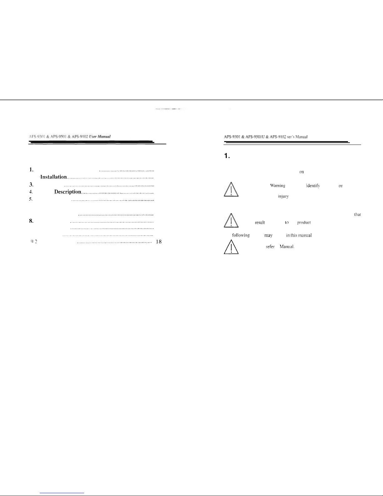
1.
SAFETY TERMS AND SYMBOLS
These terms may appear in this manual or on the product:
WARNING:
Warning statements identify condition
01-
practices
that could result
in
iqjury or loss of life.
Caution:
Caution statements identify conditions or practices that
could result in damage
to
this p~.oduct
or
other property.
The
followi~ig symbol niay appeal- in this ~iianual or on the product:
n
Attention refer to Manual.
Artisan Technology Group - Quality Instrumentation ... Guaranteed | (888) 88-SOURCE | www.artisantg.com
Page 4
APS-9301 & .APS-9501
U
&
APS-9102
ser's
Manual
APS-9301 & APS-9501U & APS-9102
ser's
Manual
1 .Before installation. please make sure the AC input voltage is correct.
a.The
,\C,
input voltage of APS-930119501 is either 115V or 230V.
xvhich can be selected. The select switch is located on the rear panel.
b.
The
4C
input voltage of APS-9102 is either 115V or 230V. which can
bt.
selected. The select switch is inside the machine.
2.Before plups input power cord to the suitable outlet or connects the
input
.,vises. please make sure all the APS-93011950119102's breakers
are
tu-ned off. It will avoid the unnecessary accident or damage to
APS-S30119501/9102.
3.Plugs the input power cord to the suitable outlet or connects the input
wire.~l:nhle to the input terminal block which is located inside panel of
APS-5301 I950 119 102. Please make sure the connections are very tight
which may a\-oid some problem happening.
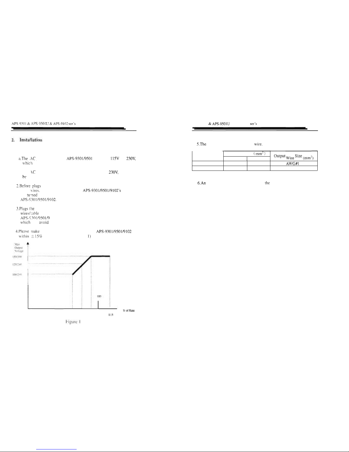
4.Plewe make
sure
the input tolerance of this APS-9301/9501/9102 is
nithi11
?
15%
of rated voltage (see figure 1)
5.The size of input wire and output wire.
6.An AC power cord is packaged in the unit of APS-930119501 as
accessory, but not available for APS
-
9102.
Model
APS
-
930119501
APS
-
9 102
85
90
95
1
15
Input
Voltage
Wire
(mm.)
AVITG#I
2
2
Input Wire Size
(mm')
115V
I
230V
3.5
5.5 3.5
Artisan Technology Group - Quality Instrumentation ... Guaranteed | (888) 88-SOURCE | www.artisantg.com
Page 5

3.
Operation
\?.I
,r?e
.ettlng contents
'll0V
',
"
220V
',
'A'
and
'v'
four keys
a.
\\.-heii any one of the keys mentioned above is pressed, the voltage
lispl la!
\vill flash one time. the APS9301/9501/9102 will go to the
xttin~
no tie
and shon- the voltage setting value.
I:.
I'the
'llOV'
Key is pressed. the output voltage will be adjusted to
10V
immediately. Mean\vliile. the voltage display will switch back
to the
reading
mode automatically-.
c.
If
the
'2201''
key is pressed for 0.2 seconds continuously ( for safety
leawn. mut be). the output voltage will be adjusted to 220V.
Ivfeannhile. the voltage di~play
\rill
switch back to the reading mode
cutornntically.
N,>te:
It
~vould not
nark
if the output voltage is setting on low range.
10-
,150~
output)
d.
1'
citliel- "A" or "v"key is PI-essed for 0.5 seconds continuously, tlie
outpu:
voltape will be adjusted. If either "A" or
"'I"
is pressed twice
c
clntinirou\ly. the output ~roltage will be adjusted immediately.
e.
The ucliustine rates are 0.1VIstep on fine ad.just mode and IV/step on
t
o:irsc. adjust mode.
f.
Tie fit-%{ six teps of adjustrnent will be spent 0.25 seconds per step.
If
1
lc
ki'?
"A*,
or
-vw
1s ' pressed continuously.
it
will spend 0.13 second
pel- stl7p
foi-
the rest steps. If the key is released. the voltage
:tl,i~~ctnicnt \~.ould be stopped and po back to the original adjustment
cprrcl
(0.25 seconds per step) automatically.
g.
Tf
the output mode is setting
ON I the indicator 'OUTPUT' would
lzlit~. the output volta~e could follow the setting voltage
ci:nultnncously
Cavtion:
If
there is no function test
of
voltage
'v'
or 'v',the voltage
output
mode would be suggested to switch to 'OFF' status
for
avoiding unnecessary mistakes occurring.
h. If
any key mentioned above is 11ot pressed for 2 seconds continuously.
APS-9301/9501/9102 would po back to the normal operation and
the voltage display could
show tlie I-eading value automatically.
2.Frequencv Setting
Frequency setting contents
'50Hz'. '60Hz'.
'A'
and
'v'
four keys
a. Either the key
'50Hz'
or the key
'60Hz'
is pressed, the frequency u-ill
be changed immediately to
50Hz. 60Hz respectively. Meantvhile the
output frequency will be changed coincidentally.
b.
lief frequency
ranges from 45Hz to 99.9Hz can be adjusted by 0.1 Hz
per step
in fine adjustment Inode and 1 Hz per step
in
coarse
adjustnient mode. The frequency ranges from IOOHz to 500Hz can be
adjusted by
1
Hz per step in fine adjustment and l0Hz per second in
coarse adjustment mode.
c. The other setting are same as
voltape qetting
3.Hi.qh /Low Voltaqe rauqe selection:
Press the
key of 'RANGE'. if the indicator lights, the output rvltage
would be setting on the high voltage range. othertvise. the system
would be setting on low voltage range. The changed range would not
cause the setting voltage to
clianee. hone~er. there is a 201ns
interruption during the voltage ranpe changing. The non-reasonable
I
-
ange changing (For example. the \-oltage sets 200V but the ranpe is
changed to the low range)
is
not acceptable by APS-9301/9501/9102.
Note: High range voltage 0 - 30011
Low range voltage 0 - 150V
4.Instmtnentation selection:
a. Press
the key of 'A', the indicator of current rvill light and the
LED
display will show the
\.slue
of current.
b.
Press the key of
'W'.
the indicator of po\i;er will light and the
LED
display will show the value of wattage.
c. Press the key of 'PF', the indicator of por5-er factor will light and tlie
LED
display will show the value of porver factor.
Artisan Technology Group - Quality Instrumentation ... Guaranteed | (888) 88-SOURCE | www.artisantg.com
Page 6

APS-92r
!
&
4PS-9501U & APS-9102
ser's
Manual
5.0~-put Enabled and Disabled Operation:
Pres: the key of
'OUTPUT'.
If the indicator of output lights, the output of
APS
-
930 1 1950 119 102 is enabled. all the LED display will show the output
valur (reading value). Otherwise. the output function is disabled, and the
LED
displa); will show the setting value. Press the
'OUTPUT'
key again
to
ckange the mode.
APS-9301 & APS-9501
U
&
APS-9102
ser's
Manual
6.Loc:k Function:
Presc the key of
'LOCK'.
If the indicator of lock lights, all the keys are
Locked (except the alarm reset). This function is good for avoiding any
miqtckes of key pressed during operation. Press again to change the mode.
7.Alai-m Reset:
If
thxe
is
over cun-ent happened. APS-9?01/950119102 would be shut
dowt-, and buzz immediately. You must press the key of
'ALARM
RESET'
to clear the fault of over current and stop the buzz. In addition,
the
key
of
'OUTPUT'
have to be pressed to get the normal output voltage
agai-1.
8.Mrmol~ Function:
-
-
As APS-930119501/9102 is equipped with EEPROM, the latest setting
will
>e memorized after the unit is turned off. If the APS-93011950119102
is
turned
on
again. the latest setting will
be
displayed.
9.Sa.,e/Recall Function:
b. Pr?ss the key of 'SIR'. if the indicator of
SAVEIRECALL
doesn't light,
Pi-e~i an! one of keys
'MEM1'
'MEM2'
'MEM3 and 'MEM4' for
0.2
seccnds. the current output setting will be saved. If the indicator of
SAk~ERECALL lights. press any one of keys 'MEMI' 'MEM2'
'MEM3'
and
'MEM4'
for 0.2 seconds, the setting saved last time via the same key
~vill be recalled as current setting.
Artisan Technology Group - Quality Instrumentation ... Guaranteed | (888) 88-SOURCE | www.artisantg.com
Page 7

APS-'1.701
&
APT-9501U & APS-9102
cer'q
Manual
APS
-
9301 & APS-9501U & APS-9102 ser's hlaiiual
4.
Panel
Description
(I
)
'ALARM RESET' Kej
Rect ke\ to cease the buzz and reqet the output.
(2)
'SIR'
Key
Sa.
e
01
Recall funct~on selectin2 key
(3
SAVEIRECALL indicator
111 the mode to save setting. the indicator doesn't light. In the mode to
recall setting. the indicator liphts.
($1
.ii
I
.(2
1).
(22)
'MEMI' 'MEM2' 'MEM3' 'MEM4' keys
W-l.eri the
S.WE/RECALL
indicator is off. the four keys are for saving
four different settings. When
the indicator are on. the keys are for
reclllin: the saved settings.
(6
1.1
23
\
'SOHz',
'60Hz'Keys
Ore
touch key for
50Hz
and 60Hz output I-
espectively.
(71
Output Frequency LED Display:
If
,he 'OUTPUT' key isn't pressed. the indicator doesn't light, and the
setiinp fi-equency value will be displayed on the output frequency LED
displaj-. Tf the 'OUTPUT' key is pressed. the indicator light, and the
auiput frequency value will be displayed on the output frequency LED
di.;pla~-.
18).(21).
'A'
m'v'
Kej-s
Th:
tn-c.
ke)-s are for frequency setting, to increase or decrease the
fl.er]uency value respectively every time they are pressed. The adjusting
rate depend< on the
'COARSE'
key arid the frequency value itself.
i9!
Coarse Indicator
If
the coarse adjustment mode is selected. the coarse indicator will light.
If t:le fine adjustment mode is selected. the coarse indicator does not light.
il0)High
/
T,ow Range Indicator of Outputvoltage
if
tiiis indicator lights. the output voltage is in the range
0 - 300V.
If this
Tn?icntor does not light. the output voltage is in the range
0 - 150V.
(
1
1
127)
'
110\
'.
'
220\
'
Keys
Onc
touch he? fn~
220V
and IIOV output respect~vely
(12)Output Voltage LED Display
If the
'OUTPUT'
Key is not pressed. the indicator doesn't light. and the
setting value will be displayed on the OutputVoltage LED Display. If the
'OUTPUT'
key is pressed, the indicator lights. and the output value
\dl
be
displayed on the Output Voltage LED
Displa!-.
(13).(28).
'A'.
'V'
keys
The two keys are for voltage setting. to increase or decrease the \-oltage
value respecti\~ely every tinie the!. al-e pressed. The adjusting rate depends
on the
'COARSE'
key.
(14)Function of Ammeter Indicator
If ammeter's indicator lights. the
\.slue
of
output current will be displayed
On the
rnultimeter LED display.
(1S)Function of Wattage Meter Indicator
If wattage meter's indicator liflits. the
\slue
of output wattage will be
displayed on the
~nultimeter LED display.
(16)
Multinieter LED Display
The value of output cul-rent. wattage or po\T'er factor \%:ill be displa!.ed
hy
respective key from
'A'.
'I?''.
to
'PF'.
(17) Function of Power Factor Meter Indicator
If powel. factor meter's indicator light<. the value of output power factor
will be displayed
on the multirneter. LED display.
(1
8)
'OUTPUT' Key
Output function enabledldisabled selection key.
(
19)Output Indicator
When output is enabled. the output indicator \%.ill li_gl?t.
(20)Power Switch
To turn on /off APS9301/9501
(25)
'
COARSE
'Key
CoarselFine adjustment selection key.
(26) ' RANGE ' Key
For the high /low output voltage's ran,oe selection.
Artisan Technology Group - Quality Instrumentation ... Guaranteed | (888) 88-SOURCE | www.artisantg.com
Page 8

APS-93C1
Pr
APS-9501U & APS-9102
ser's
Manual
(291
'.4
'Kep
Amrreter selection key of multimeter
LED
display
(30)
'I\-
'
Ke?
Wattz~e meter selection key of multimeter
LED
display.
(3
1)
'PF"
Ke?-
Power factor meter selection key of multimeter LED display.
132)
'1,OCK'
Key
Lock
/
Cnlock keyboard selection key
(33)I,ock Indicator
The li~ck indicator lights to indicate the keyboard is locked. All other keys
Except
'RESET'
are disabled.
(34)Outlet
Output socket
n
Caution:
The maximum
AC
voltage is up to 300V.
Do
not touch the
output sockets
when
the
OUTPUT
indicator appears lit.
APS-9301 & APS-9501U & APS-9102
ser's
Manual
5.
Calibration
The calibration of APS-93011950119102 has been done in the factory. If it
is
necessaly to do the calibration again. the procedures can be followed as:
1.Check if the APS-93011950119102 works normally. Then turn off
the
APS-930119501/9102.
2.Press the
'LOCK'
key continuously meanwhile turn on the
APS
-
93011905. The key of
'LOCK'
must be pressed for 2 seconds at
least until the LED Display steady. Then
APS-93011950119102 is
in
the
calibration mode.
3. Selection of APS
-
9301,APS-9501 and APS-9102
Use
the
'A'
key of frequency to choose the correct mode of APS series.
The numbers are as following:
00: means APS
-
9301
01: means APS
-
9501
02: means APS
-
9102
4. Voltmeter Calibration
a. Press the
'PF'
key , the APS-9301/9501/9102 will offset the voltmeter
and provide a approximate 240V's output voltage.
b.
Connect a standard true
RMS
voltmeter to the output socket of
APS-9301/9501/9 102
C. Use the key
'
A
'
and
'
'
of
voltage to adjust the
APS
-
93011950119102's output voltage
till
to 240V exactly.
d. Press the key
'LOCK'.
the calibration is completed.
5.Amnleter Calibration
There are low and high ranges calibration for ammeter
A.
Low range calibration
1) Make sure the Coarse indicator is extinguished. If the coarse indicator
appears lit, press 'COARSE' key to put out the indicator.
2) Press the key
'A',
APS-93011950119102 will offset the low range of
Artisan Technology Group - Quality Instrumentation ... Guaranteed | (888) 88-SOURCE | www.artisantg.com
Page 9

APS-9?9!
c!
.APS-9501
U
S(
APS-9102 ser's Manual
i\iliir.ctel. and pro1 ide a 1 10V's output voltage automatically.
3)
C
miect a ctandard true RMS ammeter and variable resistor to the
out12 ~t socket of .4PS-93011950119102.
1)
.\djuct the APS-93011950119102's output voltage or the variable
:.e\i.;rn~.
till
to ,net I .SA exactly seen from the true RMS ammeter.
5
F
cx.; the key
'LOCK'.
the cal~brat~on of the low range of ammeter of
\PT-Q3011950119102 is completed.
B.
Hrph I-
nnpe calibration
I)
hlake 5ul.e the Coarse indicator appear lit.
If
not, press the key
'COARSE'
to turn on the indicator.
71
P.-ev the key
'A'.
.APS-9301/9501/9102 will offset the high range of
am~i~ter and provide a 1 IOV's output voltage automatically.
31 C Innect a qtaiidald true RMS ammeter or a var~nble resistor to the
out17
it
wchet
of
APS-9301/95011910?
-1
1
;\cI.iuct the APS-93011950119 102's output voltage or the variable
re5lqtnr
till
to get 2.5A(9301) /4A(950l) /8.0A(9102) seen from the true
Rh'IS
ammeter.
5)
Pie55 the key
'1,OCK'.
the calibration of the high range of ammeter of
APS-930 11950 I19 102
is
completed.
6.
\k-;!Ttagc Vleter Calibration
Tliei-c are low and liigli I-anges calibration for wattage meter
A.
L(l\v
range calibration
1)
Ynke sure the Coarse indicator is extinguished, if not. press key
'COARSE'
to put out the indicator.
7)
PIES'; the key
'W'.
APS-93011950ll9102 will offset the low range of
n-ar:a~e rnetes and provide a 240V's output voltage automatically.
3
1
Cc,nnect a standard tlue RMS wattage meter and a variable resistor to
tlie
n.iti1~1t cocket of APS93011950119102.
Note: The closer the voltage sensing point of wattage meter is to the
Output socket, the better.
4)
Adjust the APS-9301/9501/91O?'s output voltage or the variable
resistor till to get 300W seen from standard
RhlS wattage meter exactly.
5) Press the key
'LOCK',
the calibratioc of the Ion range of wattage
meter of APS-9301/950119102 is completed
B.
High range calibration
1)
Make sure the coarse
indicator
appear lit. If not. press the ke!.
'COARSE'
to turn on the indicator.
2) Press
the key
'W',
APS-9301/9501/9102 will offset the high range of
wattage meter and provide a
1
l0V's output voltage autoliiatically.
3)
Connect a standard tlue RMS a attage riieter and a vanable reqi5tor to
the output socket of APS
-
93011950119
102
Note: The closer the voltage sensing point of wattage nieter is to the
Output socket, tlie better.
4)
Adjust the APS-93011950119102's output voltage or tlie variable
resistor till to get
300W(9301) I 450\17(9501) 1900W(9102) seen from the
standard RMS wattage nleter exactly.
5)
Press the key
'LOCK',
the calihl-ation
nf
the high range of wattage
meter of APS-93011950119102
is
completed.
7.
Turn off the input circuit breaker of APS-9301190519102 after the
calibration
is completed. Then turn on tlie input
c~rcuit hreaker again. the
APS
-
930 11950 119 102 will operate norri~all!..
8.Each function of calibration is independent.
If
only one or two items
need to be calibrated. it is not necessary to calibrate all the items.
9.If the calibration have to be interrupted during the calibration procedure.
you can press the key of
'PF'.
'A'.
or
'W'
of tlie voltmeter. ammeter. or
wattage meter respectively to stop the calibration.
1O.If the calibration can not be processed. please call for service
Artisan Technology Group - Quality Instrumentation ... Guaranteed | (888) 88-SOURCE | www.artisantg.com
Page 10

APS-9301
Rr
APS-9501U
Rr
APS-9102
ser's
Manual
6.
Circuit Principle
The 4PS series products are controlled by CPU and operated via keyboard.
The APS series are fully digital controlled.
The input isolate transformer has bee applied to isolate the city power from
the AFS series. And step down the input voltage for appropriate applications.
The main
AC
vou7er
is
rectified and filtered to become a very smooth
DC
source for power amplifier. Sine ware form is generated by the digital
synthesizer and filtered by a
very high impedance filter. Therefore, the sine
ware
fxm will be very stable and the distortion will be reduced.
The
APS
series have two voltage feedback systems. One is analog feedback
systen- for quick response(within loous), and the regulation will be located
In the
-ange of
k5Q.
The other is digital feedback system. The system will
read
tl-e output voltage and compare with the settings. The accuracy of
Outpu voltaze will be limited in the range of
+
0.1V.
The si-ie wave siynal is amplified by power amplifier. The power amplifier
pl-ovidzs a very clean and low distortion sine ware to the output of
APS
series through the output transformer. The offset and calibration data of
inst~~ul-lentation are stored in the EEPROM. The instrumentation would be
Calibrated automatically when the APS series is switched on.
Tiue RMS
circuit
is applied for the voltmeter and ammeter. The value of
LED
display
is
true RMS value.
For
ezsy operation. the APS series equips a memory of EEPROM. The
EEPROM will memorize the latest settings data automatically after the APS
Series
have been switched off. If the APS series is switched on again, the
CPU
cauld read all the data from the EEPROM and provide the output value
same
as
the previous setting. It is unnecessary to reset the data after APS
serie: ;Ire switched off.
APS-9301 & APS-9501U & APS-9102
ser's hlanual
7.
Block
Diagram
p?-J~~
el
Transformer
Amplifier
pF-,ij-bl
p;
Sine ware
Synthesizer
Frequency
Sensor
Cun-ent
B-
Voltage
Voltage
Sensor
Artisan Technology Group - Quality Instrumentation ... Guaranteed | (888) 88-SOURCE | www.artisantg.com
Page 11

4PS-'
70
I & APS
0501
L
&
APS
9
102
\el's
Manual
8
Specifications
This section contains a table of APS-930119501/9102 characteristics.
I
31itput
1
Digital setting via keys. Resolution: 0.lHz
Frecluency
1
Accuracy:
&o.
I
H
Z
5.0-HZ)
1
Tahle
1 : Si~ecification
7
1
1
Spwification
Description
Output Voltape
f'J.CO.0
-
Z00.OVI
Ka~irnum
)
APS-930
1
:
2.6A(O-150V). 1.3A(O-300Vj
(lurrent
/
APS-950
1
:
4.2A(O-ISOV). 2.1 A(0-300V)
I
APS-9102: S.ilA(0-ISOV). 4.2A(O-300V)
I
Lire Voltage
1
!
+O.I
%
Regulation
Digital setting via keys. Resolution: 0. IVrms
Accuracy:
+O.
1
%rdg+ 1 digit
Outrut Capacil!
P
ntcctlon
Key
Lock. OCP. Short
Low voltage range: 0.0
-
15OVac
High voltage ranpe: 0.0 - 300Vac
I
1\31
2
D~ztortlon 1'0 5'7THD
(Resistance
Load)
!
-
I
Fi.equenc>-
Stability
APS-9301 & APS-9501
U & APS-9
102
ses'~
Manual
I
OOPPM
Digital Display:
Frequency Counter
Measuring Range:
0.0-999Hz
Resolution:
0.
I
Hz
Accuracy:
+0. I Hz
RMS
Voltrneter
Measuring Range: ACO.0 - 380V
Resolution: 0.1
Vrms
Accuracy: + 1% Rdg+ IDigit
RMS Ammeter
Wattage Meter
Power Factor
Meter
Measurins
Range
:
0.000-2.000A 1.80 - 35.00A
Resolution:
I
rnA
0.0 1 A
Accuracy:
+19Ri&+5D@ +19l?dg+2D@
Measuring
Range:
0.0-360W 320 - 3500W
Resolution
:
0.1W
1W
Accuracy: r15'7cRi&+5D$ rI5CT~+I~
Measuring Range: 0.000 - 1.000
Resolution: 0.001
Accuracy:
+2% rdg + 2 digits
Line Input
115/230Vac*15 9.47-63Hz. 1 phase
I
Calibration / Front Panel Software Calibration
Power
1
Maximum 2IKJV
consumption
I I
Indoors
Operation
Environ~nent
Accessory
IF
Rated Temperature: + 1
O'C
435
OC
Operating Tempel-ature: +0 " 440
'C
Storing Temperature
:
-
10" 470
'C
..............
Operation manual. ..x 1
Line cord..
........................
.x1 (APS-930119501)
Dimensions
Weight
137mm(H) x 430(W) x 500mm(D)
(APS-930 1 I950 1)
225mm(H) x 4?0(W) x SOOmm(D)
(APS-9102)
4,
Approximate 70/25/35kg (APS-9301/9501/9102)
;
Artisan Technology Group - Quality Instrumentation ... Guaranteed | (888) 88-SOURCE | www.artisantg.com
Page 12

APS-9301
&
.4PS-95011i & APS-9102
ser's
Manual
9.
Rlaintenance
Th~s sectlon includes the basic maintenance information for
APS-930 11'950 119 102
9.1 Cleaning
To clear
APS-9301/9501/9102. use a soft cloth moistened with a small
amount
of
Water !or mild detesgent. Do not spray cleaner directly onto the instrument.
since
it
may leak into the cabinet and cause damage.
Do not use chemicals containing benzine. benzene, xylene. acetone, toluene,
or similar solvents.
Do not use abrasive cleaners on any pot
-
tion of this equipment
Trouhlcshooting here
of
the APS-9301/9501/9102
is
limited to check the
Input power fuse. If you have other difficulties of operation with your
4PS-930
11950 119
107.
please contact the Good-Will representative for help.
n
Warning:
To avoid electrical shock, the power cord protective
GI-oundinp conductor
must
be connected
to
ground.
Warning:
To avo~d
fire.
Please usc fuse of the specified type
and rate. and disconnect the power cord before replacing the
fuse.
Artisan Technology Group - Quality Instrumentation ... Guaranteed | (888) 88-SOURCE | www.artisantg.com
Page 13

Artisan Technology Group is your source for quality
new and certied-used/pre-owned equipment
• FAST SHIPPING AND
DELIVERY
• TENS OF THOUSANDS OF
IN-STOCK ITEMS
• EQUIPMENT DEMOS
• HUNDREDS OF
MANUFACTURERS
SUPPORTED
• LEASING/MONTHLY
RENTALS
• ITAR CERTIFIED
SECURE ASSET SOLUTIONS
SERVICE CENTER REPAIRS
Experienced engineers and technicians on staff
at our full-service, in-house repair center
WE BUY USED EQUIPMENT
Sell your excess, underutilized, and idle used equipment
We also offer credit for buy-backs and trade-ins
www.artisantg.com/WeBuyEquipment
REMOTE INSPECTION
Remotely inspect equipment before purchasing with
our interactive website at www.instraview.com
LOOKING FOR MORE INFORMATION?
Visit us on the web at www.artisantg.com for more
information on price quotations, drivers, technical
specications, manuals, and documentation
Contact us: (888) 88-SOURCE | sales@artisantg.com | www.artisantg.com
SM
View
Instra
 Loading...