

Page 1

AC Power Source
APS-7000E Series
USER MANUAL
GW INSTEK PART NO. 82PS-7KE00MA1
ISO-9001 CERTIFIED MANUFACTURER
www. .com
information@itm.com1.800.561.8187
Page 2

SAFETY INSTRUCTIONS
3
Table of Contents
SAFETY INSTRUCTIONS ................................................... 4
GETTING STARTED ........................................................... 8
APS-7000E Series Overview .................... 9
Appearance .......................................... 12
OPERATION .................................................................... 18
Set Up .................................................. 20
Basic Operation ................................... 36
Preset Settings ..................................... 53
Test Mode Function ............................. 57
FAQ ................................................................................ 67
APPENDIX ...................................................................... 68
Firmware Update ................................. 68
APS-7000E Default Settings ................. 70
APS-7000E Specifications ..................... 71
APS-7000E Dimensions ........................ 74
Declaration of Conformity .................... 76
INDEX............................................................................. 77
www. .com
information@itm.com1.800.561.8187
Page 3
SAFETY INSTRUCTIONS
4
SAFETY INSTRUCTIONS
This chapter contains important safety
instructions that you must follow during
operation and storage. Read the following before
any operation to ensure your safety and to keep
the instrument in the best possible condition.
Safety Symbols
These safety symbols may appear in this manual or on the
instrument.
WARNING
Warning: Identifies conditions or practices that
could result in injury or loss of life.
CAUTION
Caution: Identifies conditions or practices that
could result in damage to the APS-7000E or to
other properties.
DANGER High Voltage
Attention Refer to the Manual
Protective Conductor Terminal
Earth (ground) Terminal
www. .com
information@itm.com1.800.561.8187
Page 4
SAFETY INSTRUCTIONS
5
Do not dispose electronic equipment as unsorted
municipal waste. Please use a separate collection
facility or contact the supplier from which this
instrument was purchased.
Safety Guidelines
General
Guideline
CAUTION
Do not place any heavy object on the APS-
7000E.
Avoid severe impact or rough handling that
leads to damaging the APS-7000E.
Do not discharge static electricity to the APS-
7000E.
Use only mating connectors, not bare wires, for
the terminals.
Do not block the cooling fan opening.
Do not disassemble the APS-7000E unless you
are qualified.
(Measurement categories) EN 61010-1:2010 specifies the
measurement categories and their requirements as follows. The
APS-7000E doesn’t fall under category II, III or IV.
Measurement category IV is for measurement performed at the
source of low-voltage installation.
Measurement category III is for measurement performed in the
building installation.
Measurement category II is for measurement performed on the
circuits directly connected to the low voltage installation.
0 is for measurements performed on circuits not directly
connected to Mains.
Power Supply
WARNING
AC Input voltage range: 115/230 Vac ± 15%
Frequency: 50/60Hz
To avoid electrical shock connect the protective
grounding conductor of the AC power cord to
an earth ground.
www. .com
information@itm.com1.800.561.8187
Page 5

APS-7000E Series User Manual
6
Cleaning the APS7000E
Disconnect the power cord before cleaning.
Use a soft cloth dampened in a solution of mild
detergent and water. Do not spray any liquid.
Do not use chemicals containing harsh material
such as benzene, toluene, xylene, and acetone.
Operation
Environment
Location: Indoor, no direct sunlight, dust free,
almost non-conductive pollution (Note below)
Relative Humidity: 20%~ 80%, no condensation
Altitude: < 2000m
Temperature: 0°C to 40°C
(Pollution Degree) EN 61010-1:2010 specifies the pollution degrees
and their requirements as follows. The APS-7000E falls under degree
2.
Pollution refers to “addition of foreign matter, solid, liquid, or
gaseous (ionized gases), that may produce a reduction of dielectric
strength or surface resistivity”.
Pollution degree 1: No pollution or only dry, non-conductive
pollution occurs. The pollution has no influence.
Pollution degree 2: Normally only non-conductive pollution
occurs. Occasionally, however, a temporary conductivity caused
by condensation must be expected.
Pollution degree 3: Conductive pollution occurs, or dry, non-
conductive pollution occurs which becomes conductive due to
condensation which is expected. In such conditions, equipment
is normally protected against exposure to direct sunlight,
precipitation, and full wind pressure, but neither temperature
nor humidity is controlled.
Storage
environment
Location: Indoor
Temperature: -10°C to 70°C
Relative Humidity: ≤80%, no condensation
Disposal
Do not dispose this instrument as unsorted
municipal waste. Please use a separate collection
facility or contact the supplier from which this
instrument was purchased. Please make sure
discarded electrical waste is properly recycled to
reduce environmental impact.
www. .com
information@itm.com1.800.561.8187
Page 6
SAFETY INSTRUCTIONS
7
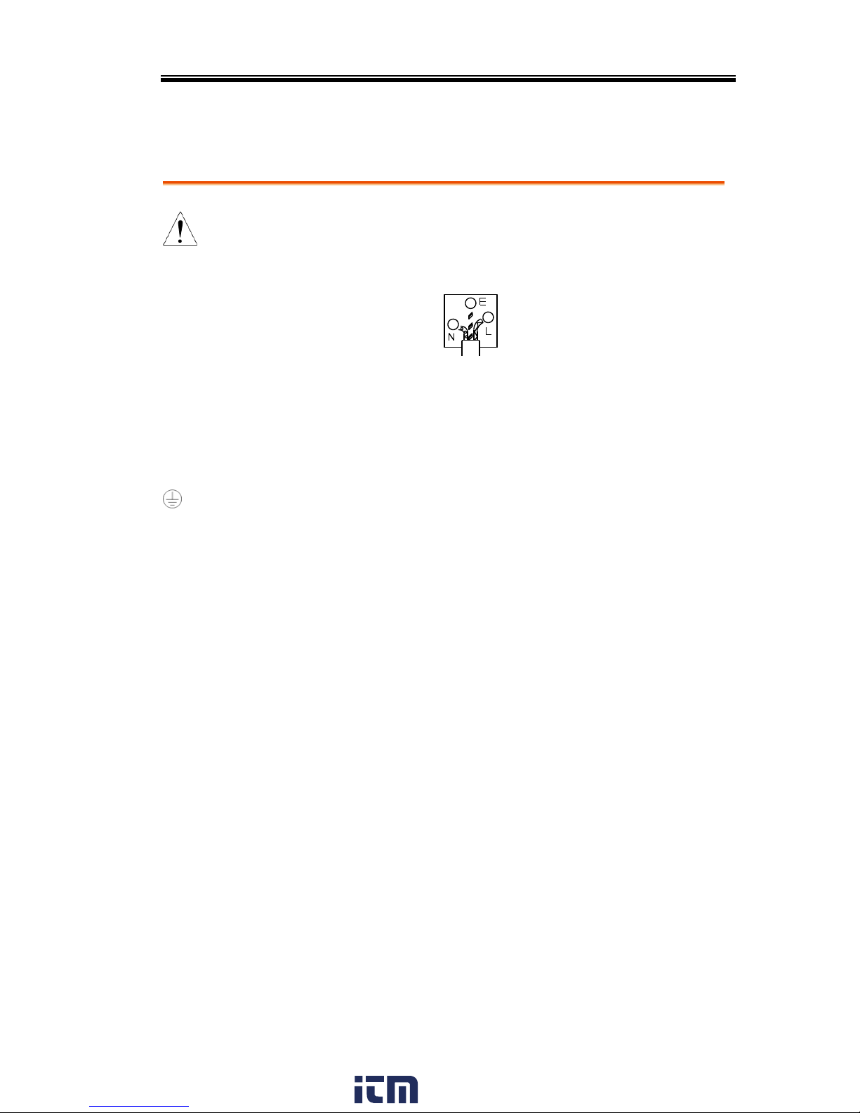
Power cord for the United Kingdom
When using the instrument in the United Kingdom, make sure the
power cord meets the following safety instructions.
NOTE: This lead/appliance must only be wired by competent persons
WARNING: THIS APPLIANCE MUST BE EARTHED
IMPORTANT: The wires in this lead are coloured in accordance with the
following code:
Green/ Yellow:
Earth
Blue:
Neutral
Brown:
Live (Phase)
As the colours of the wires in main leads may not correspond with
the coloured marking identified in your plug/appliance, proceed
as follows:
The wire which is coloured Green & Yellow must be connected to
the Earth terminal marked with either the letter E, the earth symbol
or coloured Green/Green & Yellow.
The wire which is coloured Blue must be connected to the terminal
which is marked with the letter N or coloured Blue or Black.
The wire which is coloured Brown must be connected to the
terminal marked with the letter L or P or coloured Brown or Red.
If in doubt, consult the instructions provided with the equipment
or contact the supplier.
This cable/appliance should be protected by a suitably rated and
approved HBC mains fuse: refer to the rating information on the
equipment and/or user instructions for details. As a guide, a cable
of 0.75mm2 should be protected by a 3A or 5A fuse. Larger
conductors would normally require 13A types, depending on the
connection method used.
Any exposed wiring from a cable, plug or connection that is
engaged in a live socket is extremely hazardous. If a cable or plug is
deemed hazardous, turn off the mains power and remove the cable,
any fuses and fuse assemblies. All hazardous wiring must be
immediately destroyed and replaced in accordance to the above
standard.
www. .com
information@itm.com1.800.561.8187
Page 7

APS-7000E Series User Manual
8
GETTING STARTED
This chapter describes the power source in a
nutshell, including its main features and front /
rear panel introduction.
APS-7000E Series Overview ............................................... 9
Series lineup ................................................................................................................ 9
Operating Area ........................................................................................................... 9
Main Features ........................................................................................................... 10
Accessories ............................................................................................................... 11
Appearance ..................................................................... 12
Front Panel ............................................................................................................... 12
Rear Panel ................................................................................................................. 15
www. .com
information@itm.com1.800.561.8187
Page 8
GETTING STARTED
9
APS-7000E Series Overview
Series lineup
The APS-7000E series consists of 2 models, the APS-7050E and the
APS-7100E, differing only in capacity. Note that throughout the
user manual, the term “APS-7000E” refers to both the APS-7050E
and APS-7100E, unless stated otherwise.
Model name
Max. Output Current
Power Rating
Output Voltage
APS-7050E
4.2A/2.1A
500VA
0~310.0 Vrms
APS-7100E
8.4A/4.2A
1000VA
0~310.0 Vrms
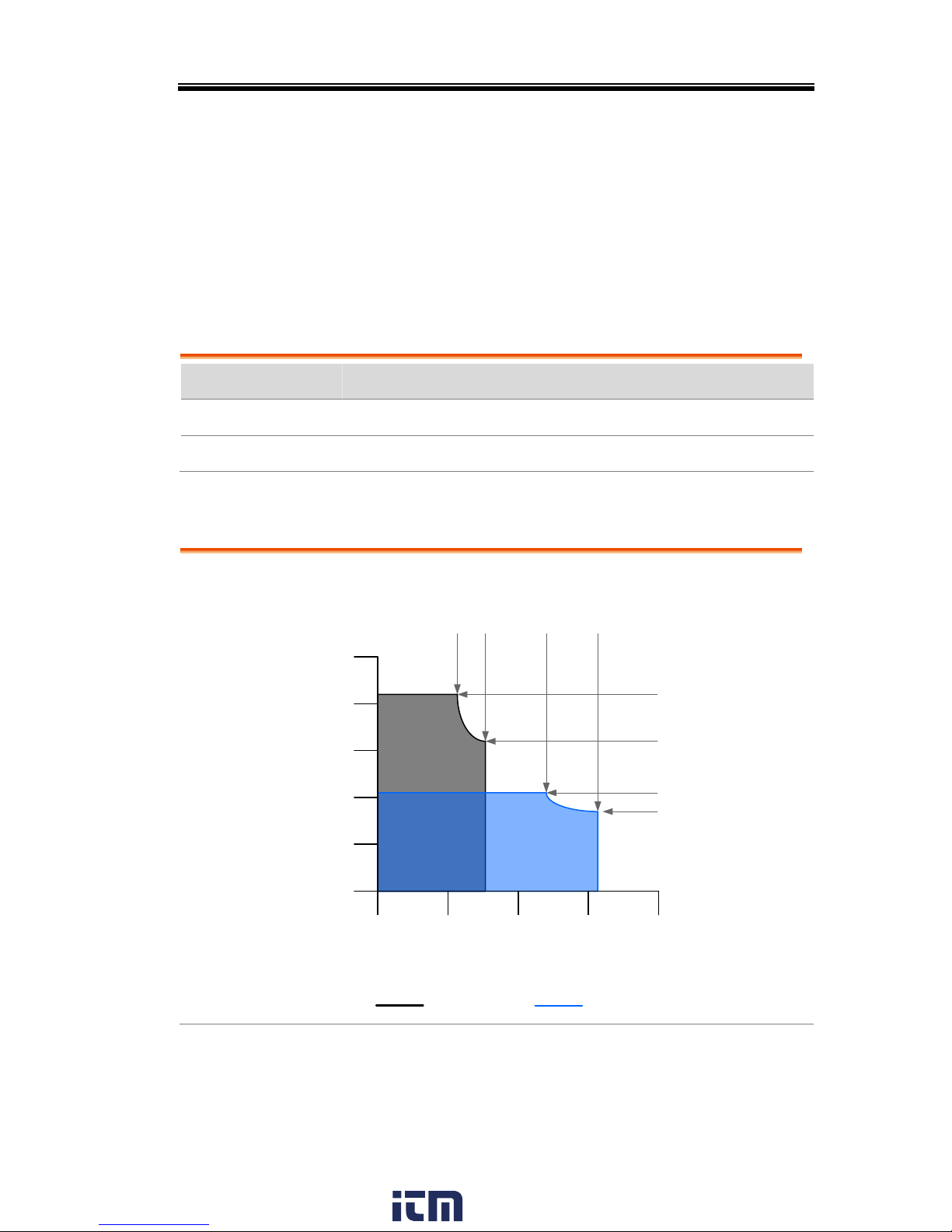
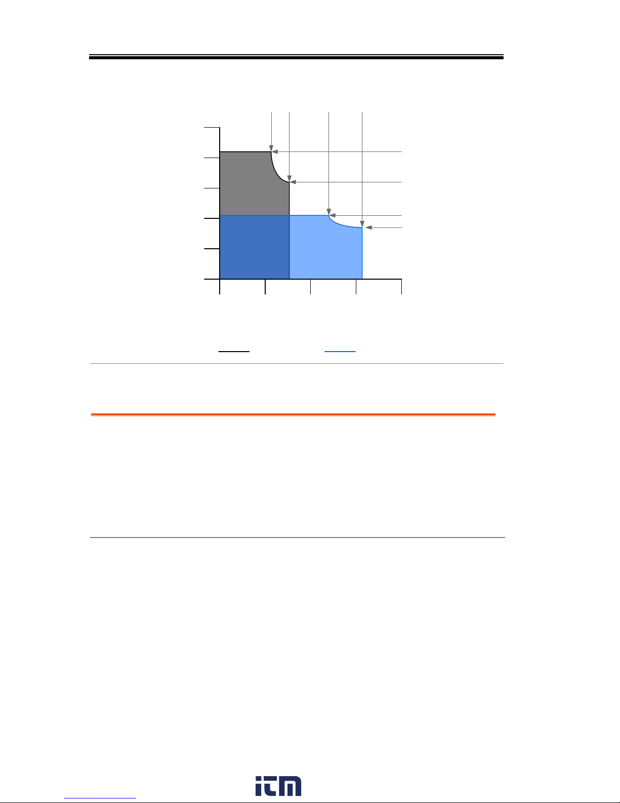
Operating Area
Voltage (V)
Current (A)
0
1
2
0
3
4
5
100
200
300 400
120 155 240
310
4.2
3.23
2.1
1.62
APS-7050E Output Operating Area
155V Range 310V Range
www. .com
information@itm.com1.800.561.8187
Page 9
APS-7000E Series User Manual
10
Voltage (V)
Current (A)
0
2
4
0
6
8
10
100
200
300 400
120 155 240
310
8.4
6.45
4.2
3.23
155V Range 310V Range
APS-7100E Output Operating Area
Main Features
Performance
Low output ripple and noise
Excellent and feature-rich measurement
capacity
Standard maximum output voltage is 310Vrms
Maximum frequency of 500Hz.
www. .com
information@itm.com1.800.561.8187
Page 10

GETTING STARTED
11
Features
OVP, OCP and OTP protection
Variable voltage, frequency and current limiter
Test function to simulate line voltage and
frequency variations
Large 4.3 inch TFT panel
Globally adjustable power inlet not restricted by
the power supply environment
USB interface is equipped as standard with the
ability to upgrade the software.
Only 88mm (2U) case height.
Interface
USB host
Accessories
Standard
Accessories
Part number
Description
CD ROM
User manual
Region dependent
Type I Power cord
(APS-7050E)
Region dependent
Type II Power cord
(APS-7100E)
62PS-7K0SC701 x1
5302-01613001 x1
Mains terminal cover set
(APS-7050E)
62PS-7K0SC401 x1
5302-01613001 x2
Mains terminal cover set
(APS-7100E)
GTL-123
Test leads: 1x red, 1x black
Optional
Accessories
Part number
Description
GRA-423
APS-7000E rack mount kit
www. .com
information@itm.com1.800.561.8187
Page 11
APS-7000E Series User Manual
12
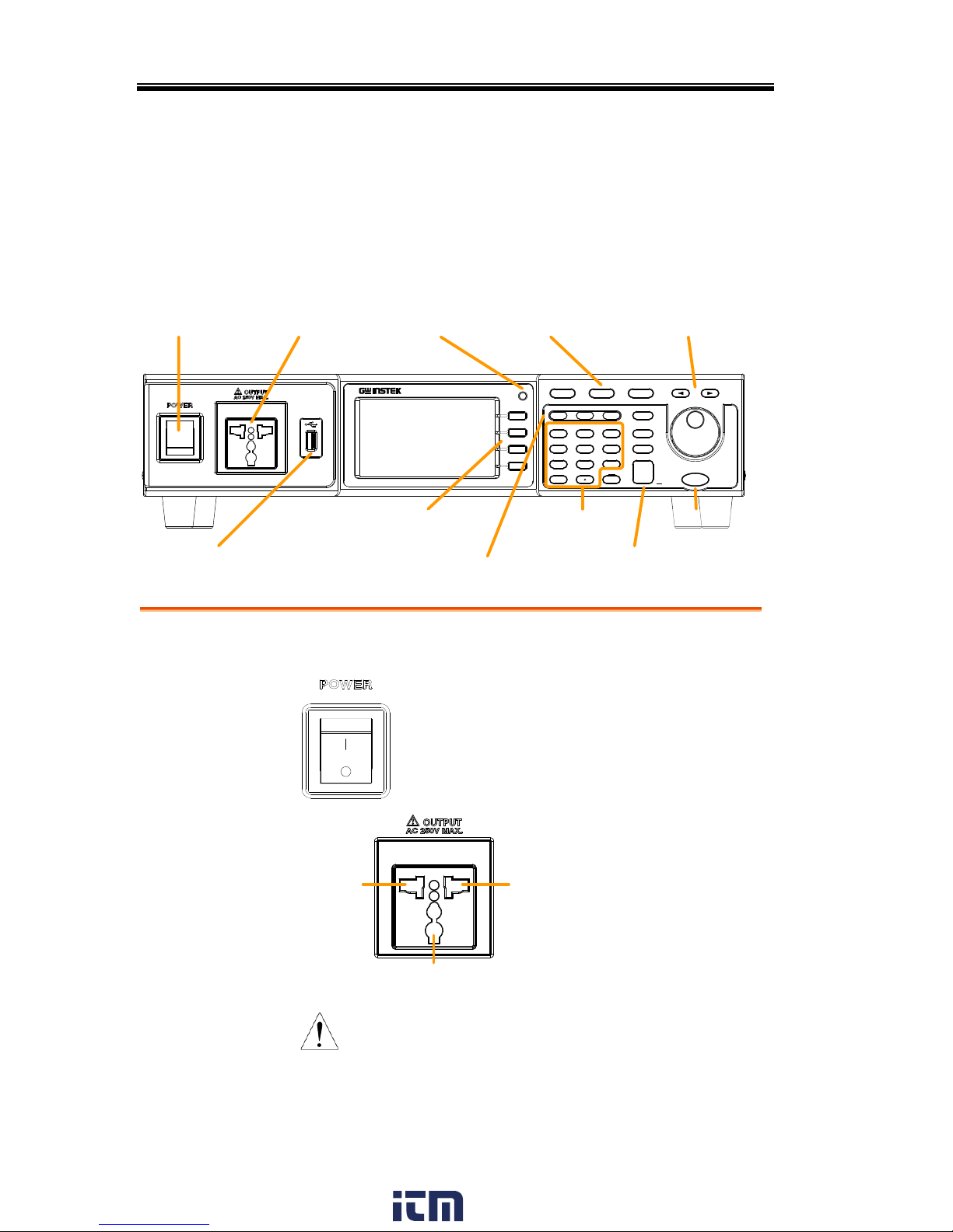
Appearance
Front Panel
APS-7050E, APS-7100E
Display
F 1
F 2
F 3
F 4
Output
: Long Push
Menu Test Preset
V
0
1
4
7
2
5
8
3
6
9
V-Limit F-Limit IPK-Limit
F I rms
Cancel
Shift
Range
Enter
Lock
ALM CLR
IPK CLR
Unlock
APS-7050E
AC Power Source
USB A port
Power
switch
Front voltage
output socket
Menu, Test,
Preset keys
LCD
display
Function keys
Display
mode key
Arrow keys,
Scroll wheel
Voltage, Frequency &
Current settings and limits
Keypad
Range, Shift, Cancel,
Enter, Lock keys
Output key
Item
Description
Power Switch
Turns on the mains power.
Front Voltage
Output Socket
Neutral
GND
Line
Output voltage
terminal using a
regional universal
plug. There is a Euro
and a Universal
regional plug.
CAUTION
Maximum allowable output voltage
and current are 250Vrms and
10Arms.
For voltages exceeding 250Vrms,
please use the rear output terminal.
www. .com
information@itm.com1.800.561.8187
Page 12
GETTING STARTED
13
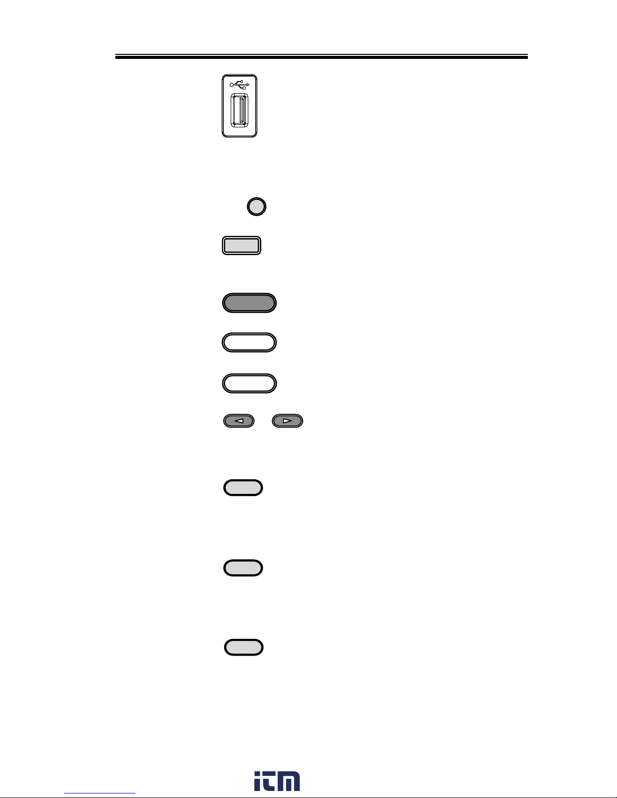
USB A Port
The USB port is used for
upgrading software.
LCD Screen
Displays the measured values or
menu system.
Display Mode
Select Key
Display
Selects between Standard mode
and Simple mode.
Function Keys
F 1
F2
Assigned to the functions
displayed on the right-hand side
of the screen.
Menu Key
Menu
Enters the Main menu or goes
back to one of the display modes.
Test Key
Test
Puts the instrument into the Test
mode.
Preset Key
Preset
Puts the instrument into Preset
mode.
Arrow Keys
The arrow keys are used to select
the digit power of a value that is
being edited.
V
V
V-Limit
Used for setting the output
voltage.
V-Limit
(Shift + V)
Used for setting the output voltage
limit value.
F
F
F-Limit
Used for setting the output
frequency.
F-Limit
(Shift + F)
Used for setting the output
frequency limit value.
I rms
I rms
IPK-Limit
Used for setting the maximum
output current.
IPK-Limit
(Shift + I rms)
Used to set the peak output
current limit value.
www. .com
information@itm.com1.800.561.8187
Page 13
APS-7000E Series User Manual
14
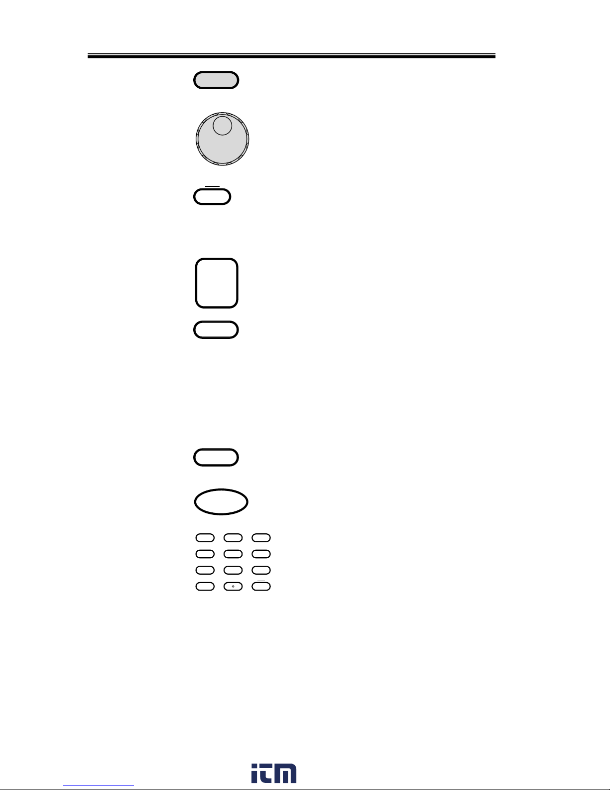
Range Key
Range
Switches between the 155V and
310V ranges.
Scroll Wheel
Used to navigate menu items or
for incrementing/decrementing
values one step at a time.
Lock Key
Lock
Unlock
Locks the number pad to prevent
accidentally changing panel
settings.
Unlock Key
(Long press)
Disables the key lock.
Enter Key
Enter
Confirms selections / settings
Cancel Key
Cancel
Clears entries that are made in the
number entry dialog when a value
is edited using the arrow keys or
the scroll wheel.
The Cancel key can also be used to
cancel function setting menus or
dialogs.
Shift Key
Shift
Turns on the shift state, which
enables shortcut operations.
Output Key
Output
Turns the output on or off.
Number Pad
0
1
4
2
5
8
3
6
9
Lock
Unlock
7
IPK CLR
ALM CLR
Used to enter values.
ALM CLR
(Shift + 6)
Clears alarms.
IPK CLR
(Shift + 9)
Clears peak current hold.
www. .com
information@itm.com1.800.561.8187
Page 14
GETTING STARTED
15
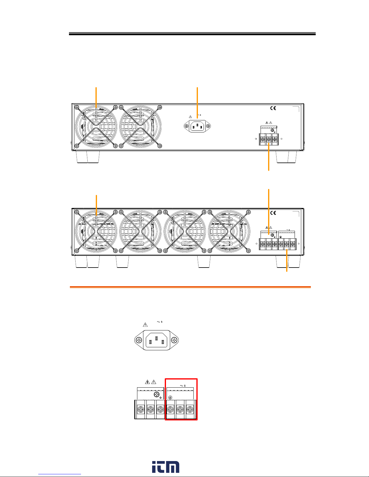
Rear Panel
SER. NO. LB
L N N L
310Vac MAX.
115 / 230V 15%
50 / 60Hz
3.6kVA MAX.
OUTPUT INPUT
115 / 230V 15%
50 / 60Hz
1.8kVA MAX.
SER. NO. LB
OUTPUT
310Vac MAX.
L N
Fan Line voltage input
Rear panel voltage
output terminal
Line voltage input
APS-7050E
APS-7100E
Fan
Line Voltage
Input
APS-7050E
115 / 230V 15%
50 / 60Hz
1.8kVA MAX.
Voltage Input: 115/230±15% VAC;
Line frequency: 50Hz/60 Hz
(Automatically switchable)
APS-7100E
L N N L
310Vac MAX.
115 / 230V 15%
50 / 60Hz
3.6kVA MAX.
OUTPUT INPUT
Voltage Input: 115/230±15%
VAC ; Line frequency:
50Hz/60 Hz (Automatically
switchable)
www. .com
information@itm.com1.800.561.8187
Page 15
APS-7000E Series User Manual
16
Rear Voltage
Output Socket
Output voltage terminal.
APS-7050E
OUTPUT
310Vac MAX.
L N
APS-7100E
L N N L
310Vac MAX.
115 / 230V 15%
50 / 60Hz
3.6kVA MAX.
OUTPUT INPUT
FAN
Temperature controlled fan.
www. .com
information@itm.com1.800.561.8187
Page 16
GETTING STARTED
17
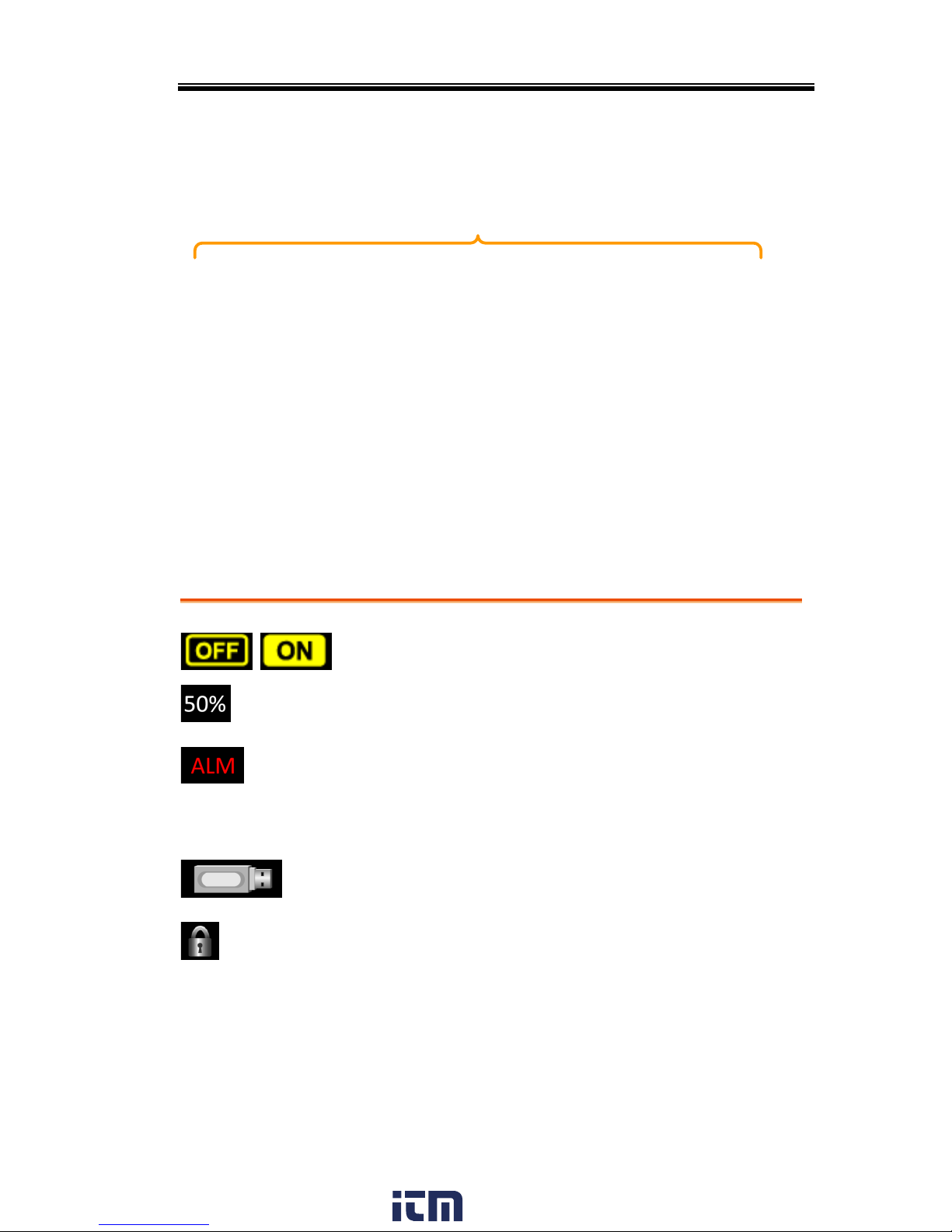
Status Bar Icons
Status bar
/
Indicates if the output is ON or OFF.
Indicates the output power as a percentage of full
scale.
The alarm icon will appear on the status bar
when one of the protection functions are tripped.
Applies to Over Power, Over Irms, Over Ipeak
and Over Temperature protection.
Indicates that a USB drive is detected in the front
panel host port.
Indicates that the panel lock is active.
www. .com
information@itm.com1.800.561.8187
Page 17

APS-7000E Series User Manual
18
OPERATION
Set Up ............................................................................. 20
Line Voltage Connection (APS-7100E) ................................................................ 20
Power Up .................................................................................................................. 23
Output Terminals .................................................................................................... 24
Using the Rack Mount Kit ..................................................................................... 28
How to Use the Instrument ................................................................................... 28
Reset to Default Settings ........................................................................................ 32
View System Version and Serial Number ............................................................. 33
LCD Configuration ................................................................................................. 34
Buzzer ........................................................................................................................ 35
Basic Operation .............................................................. 36
Setting the Voltage Range ....................................................................................... 36
Setting the Voltage Limit ........................................................................................ 37
Setting the Output Voltage ..................................................................................... 38
Setting the Frequency Limit ................................................................................... 40
Setting the Output Frequency ................................................................................ 41
Setting the Peak Current Limit .............................................................................. 42
Setting the Current RMS Level .............................................................................. 45
Alarm Clear ............................................................................................................... 48
Display Modes .......................................................................................................... 49
Panel Lock ................................................................................................................ 51
Turning the Output On .......................................................................................... 52
Preset Settings ................................................................ 53
Save Preset Settings to Local Memory .................................................................. 53
Load Preset Settings to Local Memory ................................................................. 54
Manage Preset Settings ............................................................................................ 55
Test Mode Function ......................................................... 57
Test Mode Overview ............................................................................................... 58
Test Settings ............................................................................................................. 60
Save a Test to Local Memory ................................................................................. 62
www. .com
information@itm.com1.800.561.8187
Page 18

OPERATION
19
Recall a Test from Local Memory ......................................................................... 62
Manage Test Settings ............................................................................................... 63
Running a Test ......................................................................................................... 65
www. .com
information@itm.com1.800.561.8187
Page 19
APS-7000E Series User Manual
20
Set Up
Line Voltage Connection (APS-7100E)
Background
The APS-7100E is equipped with an input
power terminal that can accept 115V/230V ±
15%. To connect or replace the power cord (GW
Instek part number: APS-7100E: 4300-31000101,
use the procedure below:
Warning
The following procedure should only be attempted
by competent persons.
Ensure the AC power cord is not connected to
power.
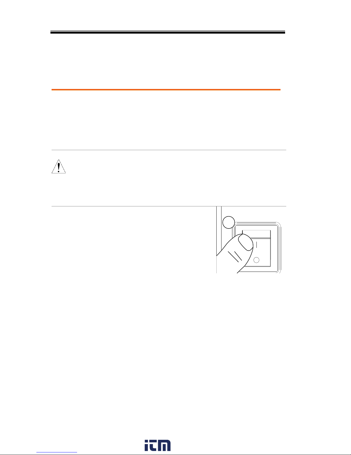
Removal
1. Turn off the power switch.
1
APS-7100E
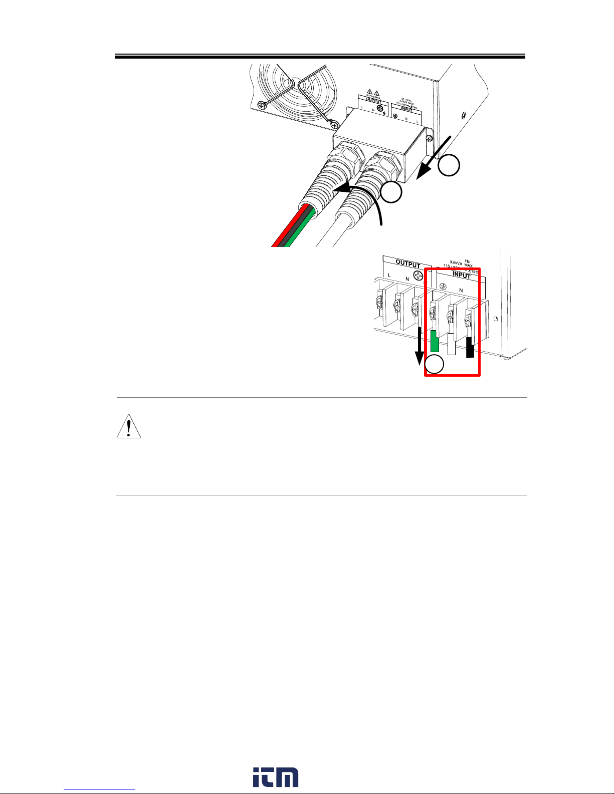
2. Unscrew the power cord strain relief on the rear
output socket.
3. Remove the 2 screws holding the power cord
cover and remove.
www. .com
information@itm.com1.800.561.8187
Page 20
OPERATION
21
APS-7100E
3
2
4. Remove the AC
power cord wires.
4
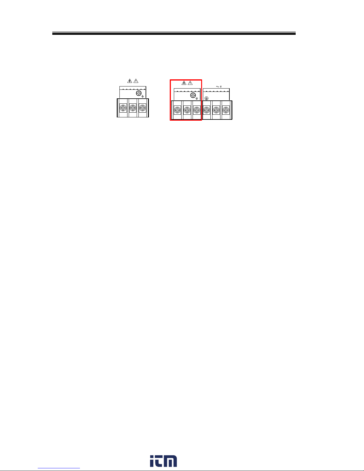
CAUTION
The power line inputs for the APS-7100E are on the
outer cluster of terminals.
The terminals to the inner of the panel are the rear
panel outputs.
www. .com
information@itm.com1.800.561.8187
Page 21
APS-7000E Series User Manual
22
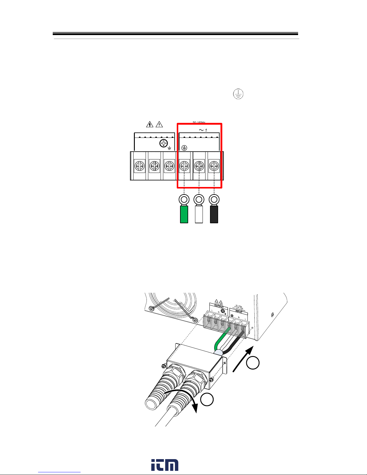
Installation
1. Connect the AC power cord wires to the AC
input terminals.
White/Blue Neutral (N)
Green/Green-yellowGND ( )
Black/Brown Line (L)
L N N L
310Vac MAX.
115 / 230V 15%
50 / 60Hz
3.6kVA MAX.
OUTPUT INPUT
Line
Neutral
2. Re-install the power cord cover.
3. Screw the power cord strain relief back onto the
cover.
2
3
www. .com
information@itm.com1.800.561.8187
Page 22
OPERATION
23
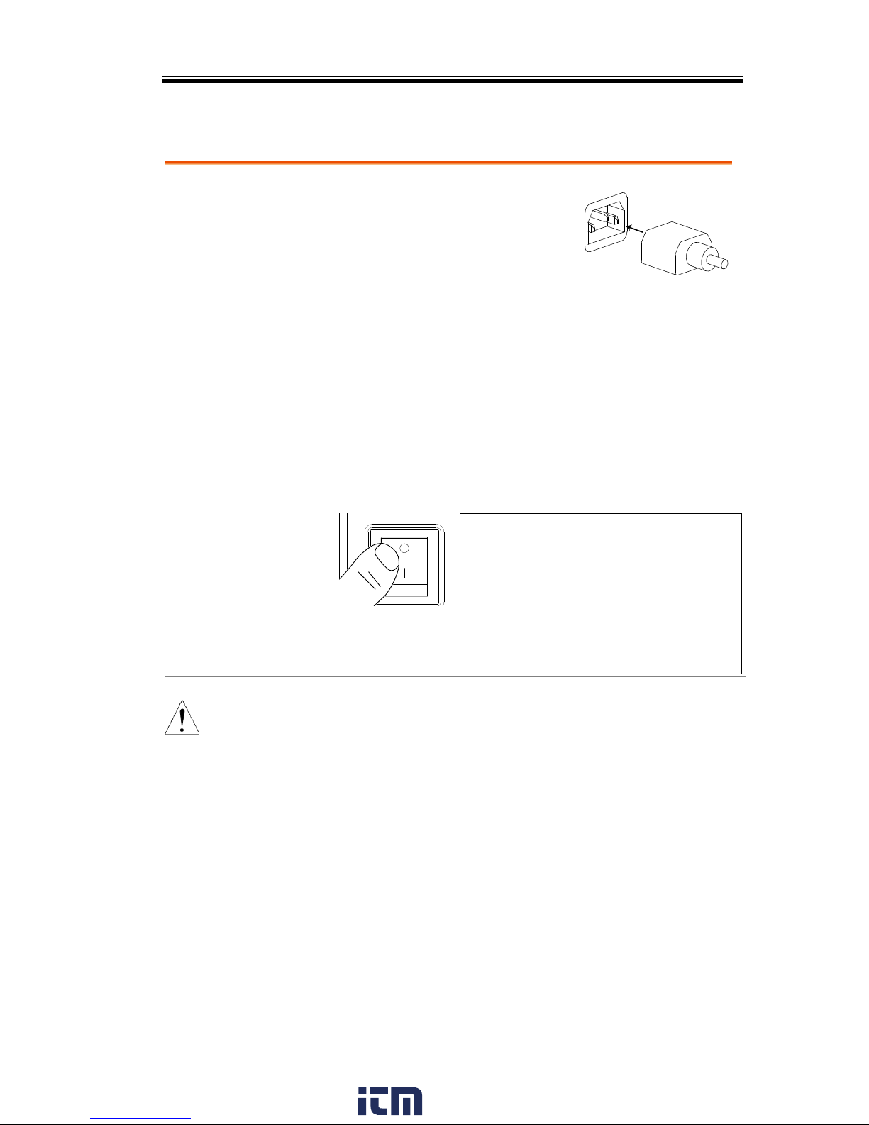
Power Up
Steps
1. Socket type: Connect the
power cord to the rear
panel socket.
Input Power Terminal:
Connect the power cord to
the input power
terminals.
Page 20
2. Press the POWER key. The splash screen will
appear momentarily before the continuous
mode screen appears with the settings loaded.
CAUTION
The power supply takes around 10 seconds to fully
turn on and shutdown.
Do not turn the power on and off quickly.
www. .com
information@itm.com1.800.561.8187
Page 23
APS-7000E Series User Manual
24
Output Terminals
Background
The output terminals can be output from either
the front panel or from the rear panel. The
outputs are limited to 4.2A/2.1A (APS-7050E)
or 8.4A/4.2A(APS-7100E).
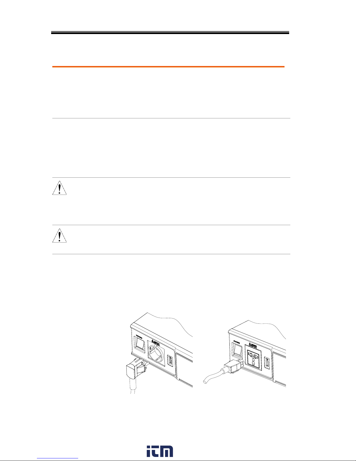
Supported plugs
Multi-region terminal Socket
Supported Standards:
IEC, North America, Japan.
EURO CEE type universal plug
WARNING
Dangerous voltages. Ensure that the power to the
instrument is disabled before handling the power
supply output terminals. Failing to do so may lead
to electric shock.
CAUTION
For the front panel output, the maximum output
voltage is 250VAC and current is 10A.
Front Panel
Output
Connection
1. The front panel has a multi-region power
socket depending on the socket type.
2. Insert the plug from the DUT into the socket.
EURO CEE socket
IEC North America, Japan
www. .com
information@itm.com1.800.561.8187
Page 24

OPERATION
25
3. Turn the power on. The AC power supply is
now ready to power the DUT.
Rear Panel Output
Connection
The rear panel output is used to supply higher
power DUTs. The rear panel output connection
is similar to the universal rear panel line input
connection on the APS-7100E.
1. Disconnect the unit from the mains power
socket and turn the power switch off.
2. Unscrew the power cord strain relief.
3. Remove the 2 screws holding the power cord
cover and remove.
APS-7050E
3
2
APS-7100E
3
2
www. .com
information@itm.com1.800.561.8187
Page 25

APS-7000E Series User Manual
26
CAUTION
For the APS-7100E, there is a single bank for the
input and output terminals. Ensure the correct
terminals are connected. The APS-7050E only has
a single bank of output terminals on the rear
panel.
Installation
4. Connect the output AC power cord wires to
the output terminals.
Black Neutral (N)
Green GND ( )
Red Line (L)
L N N L
310Vac MAX.
115 / 230V 15%
50 / 60Hz
3.6kVA MAX.
OUTPUT INPUT
Line
Neutral
Ground
Ground
Neutral
Line
APS-7100E shown. The input terminals are already
connected and shows which output terminals are
to be connected.
5. Re-install the power cord cover.
6. Screw the power cord strain relief back onto
the power cord cover.
www. .com
information@itm.com1.800.561.8187
Page 26

OPERATION
27
APS-7100E
5
6
APS-7050E
5
6
7. Turn the power on. The AC power supply is
now ready to power the DUT.
www. .com
information@itm.com1.800.561.8187
Page 27

APS-7000E Series User Manual
28
Using the Rack Mount Kit
Background
The APS-7000E series has an optional Rack
Mount Kit (GW Instek part number: GRA-423).
The APS-7050E and APS-7100E are designed to
fit into a 2U rack height. Please see your
distributor for further rack mount details.
Rack mount
diagram
CAUTION
Ensure adequate ventilation is provided when
using the rack mount. Ensure that a gap of at least
50mm is given for the side air intakes. Failure to
do so may cause the instrument to overheat.
How to Use the Instrument
Background
The APS-7000E AC power supplies generally
use the scroll wheel, arrow keys and Enter keys
to edit numerical values or to select menu
options.
Menu navigation is performed using the menu
keys and function keys on the front panel.
The following section will explain some of
these concepts in detail.
www. .com
information@itm.com1.800.561.8187
Page 28

OPERATION
29
Selecting Menu
Items
1. Turn the scroll wheel to select
parameters in menus and lists. The
selected parameter will be
highlighted in orange. The scroll
wheel is also used to
increment/decrement setting
values.
2. Press the Enter key to edit the
parameter or to enter the selected
menu.
Enter
Example
Selected parameter
The following is an example of the menu list that
appears when the Menu key is pressed.
Using the Keypad
to edit parameter
values
When editing a value the keypad can be used
to directly enter the desired value.
1. Type the value of the
parameter using the
keypad.
0
1
4
2
5
8
3
6
9
Lock
Unlock
7
IPK CLR
ALM CLR
2. Press the Enter key to confirm the
edit.
Enter
www. .com
information@itm.com1.800.561.8187
Page 29

APS-7000E Series User Manual
30
Example
Parameter
Using the Arrow
Keys and Scroll
wheel to edit
parameter values
Use the arrow keys to select a digit power and
then use the scroll wheel to edit the value by
that power.
1. Use the arrow keys to move the
cursor to the digit of the desired
power.
2. Turn the scroll wheel to edit the
value by the resolution of the
selected digit.
Cursor
3. Repeat the steps above for all the relevant
digits.
4. Press the Enter key to confirm the
edit.
Enter
www. .com
information@itm.com1.800.561.8187
Page 30

OPERATION
31
Note
By default the cursor starts at the lowest power
digit.
Using the
Function Keys
The function keys (F1 ~ F4) are quick settings
keys, the function of which depends on the
current menu or operation.
1. Press the function key that corresponds to the
setting directly to its left.
2. The setting or parameter is immediately
executed.
Display
F 1
F 2
F 3
F 4
Output
: Long Push
Menu Test Preset
V
0
1
4
7
2
5
8
3
6
9
V-Limit F-Limit IPK-Limit
F I rms
Cancel
Shift
Range
Enter
Lock
ALM CLR
IPK CLR
Unlock
APS-7050E
AC Power Source
Function keys
Corresponding quick
settings
3. Repeat the steps above for all the relevant
digits.
www. .com
information@itm.com1.800.561.8187
Page 31

APS-7000E Series User Manual
32
Reset to Default Settings
Background
The default settings can be restored from the
Menu key settings. See page 70 for the default
factory settings.
Steps
1. Press the Menu key. The Menu
settings will appear on the display.
Menu
2. Use the scroll wheel to go to item 4, Default
Setting.
3. Press Enter x2 to restore the default settings.
Default settings
www. .com
information@itm.com1.800.561.8187
Page 32

OPERATION
33
View System Version and Serial Number
Background
The Menu>System Information setting
displays the serial number and version
number.
Steps
1. Press the Menu key. The Menu
setting will appear on the display.
Menu
2. The system information should now be listed
on the display.
If not, use the scroll wheel to go to item 1,
System Information.
System
Information
www. .com
information@itm.com1.800.561.8187
Page 33

APS-7000E Series User Manual
34
LCD Configuration
Background
The LCD Configuration setting sets the
brightness, contrast and saturation level of the
LCD display.
Steps
1. Press the Menu key. The Menu
settings will appear on the display.
Menu
2. Use the scroll wheel to go to item 3, LCD
Configuration and press Enter.
3. Set the brightness, contrast and saturation.
Contrast(%)
1 ~ 100% (Default=50%)
Brightness(%)
1 ~ 100% (Default=50%)
Saturation(%)
1 ~ 100% (Default=50%)
Exit
4. Press Exit[F4] to exit from the
Ramp Control settings.
Default Settings
5. Press Default[F3] to set all the LCD settings to
50%.
LCD settings
Default
settings
www. .com
information@itm.com1.800.561.8187
Page 34

OPERATION
35
Buzzer
The Buzzer setting turns the buzzer sound on or off for key presses
and alarms.
Steps
1. Press the Menu key. The Menu
setting will appear on the display.
Menu
2. Use the scroll wheel to go to item 2, MISC
Configuration and press Enter.
3. Go to the Buzzer setting using the scroll wheel
and press Enter. Turn the setting on or off and
press Enter again to confirm.
Buzzer
ON, OFF
Exit
4. Press Exit[F4] to exit from the
MISC Configuration settings.
Example
Settings
www. .com
information@itm.com1.800.561.8187
Page 35

APS-7000E Series User Manual
36
Basic Operation
This section describes the basic operations required to operate the
power supply.
Setting the Voltage Range → from page 36
Setting the Voltage Limit → from page 37
Setting the Output Voltage → from page 38
Setting the Frequency Limit → page 40
Setting the Output Frequency → page 41
Setting the Peak Current Limit → from page 42
Setting the Current RMS Level → from page 45
Clearing the Alarm → from page 48
Setting the Display mode → from page 49
Panel lock → from page 51
Turning the Output on/off → from page 52
Before operating the power supply, please see the Getting Started
chapter, page 8.
Setting the Voltage Range
Background
The Range setting determines the general outlet
voltage range. The ranges available correspond
to common mains output voltage standards.
Steps
1. Press Range to access the Range
menu.
Range
2. Set the voltage range with the scroll wheel or
with the F1 ~ F4 soft-keys.
Range
AUTO, 310V, 155V
3. Press Enter to confirm the Range setting.
www. .com
information@itm.com1.800.561.8187
Page 36

OPERATION
37
Range setting
Soft-key
settings
F1
F2
F3
F4
Note
If the range is changed from 155V to 310V, the
Irms and IPK values will automatically be changed
to a lower value. If the range is changed from 300V
to 155V, the Irms and IPK values remain the same.
If the voltage range is changed when the output is
on, the output will be automatically turned off.
Setting the Voltage Limit
Background
Setting the voltage limit allows the output
voltage to be set to any level within the voltage
limit (V Limit) range.
Steps
1. Press Shift + V to access the Volt
Limit menu.
Shift
+
V
V-Limit
2. Set the voltage limit with the scroll wheel or
with the F3 ~ F4 soft-keys. The MAX and MIN
soft-keys set the limit to the maximum and
minimum, respectively.
Range
10% of full range ~ full range
Soft-keys
MAX, MIN
3. Press Enter to confirm the voltage limit setting.
www. .com
information@itm.com1.800.561.8187
Page 37

APS-7000E Series User Manual
38
Volt Limit
Min/Max
settings
F3
F4
Note
Each voltage range (155V, 310V) has an
independent voltage limit.
Setting the Output Voltage
Background
The voltage setting sets the voltage level of the
power supply.
Note
Before setting the power supply voltage level, set
the voltage range and voltage limit.
Steps
1. Press the V key. The ACV
parameter will be editable.
V
V-Limit
2. Set the voltage with the scroll wheel/keypad or
with the F1 ~ F4 soft-keys.
Range
0 volts ~ full range
Soft-keys
DEF1, DEF2, MAX, MIN
3. Press Enter to confirm the voltage setting.
Preset Settings
The DEF1 and DEF2 preset settings are user
defined settings. By default they are set to 0.00
volts. The MAX and MIN soft-keys set the
voltage to the maximum and minimum,
respectively.
www. .com
information@itm.com1.800.561.8187
Page 38

OPERATION
39
4. Press the V key and set the desired voltage with
the scroll wheel/keypad.
Range
0 volts ~ full scale of voltage range
5. Press and hold the DEF1 or DEF2 soft-key until
“Saved to DEF1/2” is displayed. This will save
the voltage setting to the DEF1 or DEF2 softkey.
Note
Trying to set the voltage outside of the voltage
limit/range will result in a voltage setting error
being displayed on the screen.
The voltage level can be set when the output is on.
Example
Voltage setting
Preset voltage
settings
F3
F4
F1
F2
www. .com
information@itm.com1.800.561.8187
Page 39

APS-7000E Series User Manual
40
Setting the Frequency Limit
Background
Setting the frequency limit allows the frequency
output to be set to any level within the limit
range.
Steps
1. Press Shift + F to access the Freq
Limit menu.
Shift
+
F
F-Limit
2. Set the frequency limit with the scroll
wheel/keypad or with the F3 ~ F4 soft-keys.
The MAX and MIN soft-keys set the frequency
limit to the maximum and minimum,
respectively.
Range
45.00 ~ 500.0Hz
Soft-keys
MAX, MIN
3. Press Enter to confirm the limit setting.
Example
Freq Limit
Min/Max
settings
F3
F4
www. .com
information@itm.com1.800.561.8187
Page 40

OPERATION
41
Setting the Output Frequency
The frequency setting sets the frequency of the output.
Background
Before setting the frequency, set the frequency
limit.
Steps
1. Press the F key. The FREQ
parameter will be editable.
F
F-Limit
2. Set the frequency with the scroll wheel/keypad
or with the F1 ~ F4 soft-keys.
Range
45.00 ~ 500.0Hz
Soft-keys
DEF1, DEF2, MAX, MIN
3. Press Enter to confirm the frequency setting.
Preset Settings
The DEF1 and DEF2 preset settings are user
defined settings. By default they are set to
50.00Hz and 60.00Hz, respectively. The MAX
and MIN soft-keys set the frequency to the
maximum and minimum, respectively.
4. Press the F key and set the desired frequency
with the scroll wheel/keypad.
Range
45.00 ~ 500.0Hz
5. Press and hold the DEF1 or DEF2 soft-key until
“Saved to DEF1/2” is displayed. This will save
the frequency setting to the DEF1 or DEF2 softkey.
www. .com
information@itm.com1.800.561.8187
Page 41

APS-7000E Series User Manual
42
Example
Frequency setting
Preset frequency
settings
F3
F4
F1
F2
Note
Trying to set the frequency outside of the frequency
limit will result in a frequency setting error being
displayed on the screen.
The frequency can be set when the output is on.
Setting the Peak Current Limit
Background
Setting the peak current limit sets a limit on the
current that can be sourced by the power
supply.
Note
When the peak current limit is tripped, an alarm
will sound. Press Shift + 9 to clear the Ipk alarm.
Shift+6 can also clear the Ipk alarm. See page 48
for details.
Steps
1. Press Shift + I rms to access the
Ipeak menu.
Shift
+
I rms
IPK-Limit
www. .com
information@itm.com1.800.561.8187
Page 42

OPERATION
43
2. Set the peak current with the scroll
wheel/keypad or with the F3 ~ F4 soft-keys.
The MAX and MIN soft-keys set the peak
current to the maximum and minimum,
respectively.
Range
10% ~ 100% peak current value. The
peak current value depends on the
selected voltage range.
Soft-keys
MAX, MIN
3. Press Enter to confirm the peak current setting.
Example
Ipeak
Min/Max
settings
F3
F4
Delay Time
Settings
The Delay Time setting essentially defines how
long the measurement of the peak current must
be sustained for before it is recognized. By
default the delay time is turned off.
Load on
Ipk Limit
reached
I Pk Limit Delay
I
Ipk Limit acknowledged,
protection triggered
T
www. .com
information@itm.com1.800.561.8187
Page 43

APS-7000E Series User Manual
44
1. Press Shift + I rms and then press DELAY[F2].
2. Set the desired delay time with the scroll
wheel/keypad or with the F3 ~ F4 soft-keys.
The MAX and MIN soft-keys set the delay time
to the maximum and minimum, respectively.
Range
0(off) ~ 10 seconds
Soft-keys
MAX, MIN
3. Press Enter to confirm the delay time setting.
Example
Delay Time
Min/Max
settings
F3
F4
IPK Measurement
Range Settings
The IPK Range settings allow you to manually set
the peak current measurement range. By default
this setting is set to AUTO.
1. Press Shift + I rms and then press IPK Range[F1].
2. Set the desired range with the scroll wheel.
Range
AUTO, 0.28A, 1.4A, 14A, 70A
3. Press Enter to confirm the IPK Range setting.
www. .com
information@itm.com1.800.561.8187
Page 44

OPERATION
45
Example
IPK Range settings
Setting the Current RMS Level
Background
The I rms setting sets the root mean square
current.
Steps
1. Press I rms to access the I rms
menu.
I rms
Ipk-Limit
2. Set the I rms level with the scroll wheel/keypad
or with the F3 ~ F4 soft-keys. The MAX and
MIN soft-keys set the I rms level to the
maximum and minimum, respectively.
Range
0.00 ~ full scale A (dependant on
the voltage range)
Soft-keys
MAX, MIN
3. Press Enter to confirm the current setting.
Example
Irms
Min/Max
settings
F3
F4
www. .com
information@itm.com1.800.561.8187
Page 45

APS-7000E Series User Manual
46
Note
Setting the I rms level to 0.00 will disable OCP.
Setting I rms to 0A is dangerous.
I rms Delay Time
Settings
The Delay Time setting defines how long the I
rms measurement must be sustained for before
it is recognized. By default the I rms delay time
is turned off.
Load on
Irms
Limit
reached
Irms Limit Delay
I
Irms Limit
acknowledged,
protection triggered
T
Irms Limt
4. Press I rms and then press DELAY[F2].
5. Set the desired delay time with the scroll
wheel/keypad or with the F3 ~ F4 soft-keys.
The MAX and MIN soft-keys set the delay time
to the maximum and minimum, respectively.
Range
0(off) ~ 10 seconds
Soft-keys
MAX, MIN
6. Press Enter to confirm the delay time setting.
www. .com
information@itm.com1.800.561.8187
Page 46

OPERATION
47
Example
Delay Time
Min/Max
settings
F3
F4
OC Fold Settings
The over current fold back settings allow the
APS-7000E to work as either a constant voltage
source or a constant current source.
While the unit is sourcing less current than the
Irms current limit, the APS-7000E will act as a
constant voltage source. In this mode, the
voltage level will remain constant while the
current level may vary. This is the normal
operating mode.
When the current level reaches the Irms limit,
the APS-7000E will act as a constant current
source. In this mode the current is constant and
the voltage level varies. When the current
subsides below the Irms limit again, the unit
will again act as a constant voltage source.
When OC Fold is turned off, the APS-7000E will
act as a current limiting power source when the
Irms limit has been reached.
Vrms
setting
ACV
I
Irms limit
Irms
www. .com
information@itm.com1.800.561.8187
Page 47

APS-7000E Series User Manual
48
Note
OC-FOLD can only be active when the I rms level is
greater than 0.
7. Press I rms and then press OC-FOLD[F1] toggle
the OC-Fold function on or off.
OC-Fold setting
Alarm Clear
Background
The ALM CLR (Alarm Clear) function will clear
any Over Power, Over Irms, Over Ipeak and
Over Temperature alarms.
Applicable
Alarms
OVER POWER, OVER IRMS, OVER IPEAK,
OVER TEMPERATURE
Steps
1. Press Shift + 6 to clear any alarms.
Shift
+
6
ALM CLR
Example
Alarm message
ALM indicator
www. .com
information@itm.com1.800.561.8187
Page 48

OPERATION
49
Display Modes
The APS-7000E power supply has two display modes. The
standard display mode shows the power supply setup on the left
and the 3 configurable measurements on the right. The simple
display mode shows all measurement items available on the APS7000E.
Steps
1. Press the Display key.
2. The display mode will toggle each
time the key is pressed.
Display
Standard Mode
Settings Measurements
Configurable
measurements
Hold
measurement
Simple Mode
Measurement Items
Hold
measurement
Configuring the
Standard Mode
Measurements
1. Press the Meas Item1, Item2 or Item3
soft-key.
www. .com
information@itm.com1.800.561.8187
Page 49

APS-7000E Series User Manual
50
2. Use the scroll wheel to select a measurement
item and press Enter to confirm.
Sets third measurement item to frequency
Hold
Measurement
The Hold function will “hold” the current
measurements on the display. Measurements
won’t be updated on the display until the
function is released.
Press HOLD[F4] to toggle hold on or off.
www. .com
information@itm.com1.800.561.8187
Page 50

OPERATION
51
Panel Lock
The panel lock feature prevents settings from being changed
accidentally. When activated, all keys and knobs except the
Lock/Unlock key and the Output key (if active) will be disabled.
Activate the panel
lock
Press the Lock key to active the
panel lock. “Keys locked” appears
on the display.
A lock icon will appear in the top
corner when the panel keys are
locked.
Lock
Unlock
Disable the panel
lock
Hold the Lock key for ~3 seconds to
disable the panel lock. “Keys
unlocked” will appear on the
display and the padlock icon will
disappear.
Lock
Unlock
(hold)
Example
Message Lock icon
www. .com
information@itm.com1.800.561.8187
Page 51

APS-7000E Series User Manual
52
Turning the Output On
When the output is turned on, the DUT can be connected to either
the rear panel output or the front panel output.
Warning
Both of these outputs are electrically linked. Only one
DUT should be connected to any one of the outputs at
a time. Using both outputs at the same time is not
supported. Using the front and rear outputs are the
same time could cause dangerous operating
conditions. See page 24 for details about using the
output terminals or sockets.
Turn Output On
Press the Output key. The Output
key will light up and ON will be
displayed in the status bar to
indicate that the output is on.
Output
Turn Output Off
Press the Output key. The Output
key light will go out and OFF will
be displayed in the status bar to
indicate that the output is off.
Output
www. .com
information@itm.com1.800.561.8187
Page 52

OPERATION
53
Preset Settings
Save Presets to Local Memory → from page 53
Recall Presets to Local Memory → from page 54
Manage Preset Settings → from page 55
Save Preset Settings to Local Memory
Up to 10 preset settings can be saved to internal memory.
Steps
1. Press Preset and then hold a
number key (0~9) to save the
present settings to the
corresponding memory
number.
Preset
+
0
~
9
(hold)
Presets
M0 ~ M9
2. Press the Preset key again to exit from the preset
mode.
Example
For example, pressing Preset & holding 1 will
save the present settings to memory slot 1
(saved to M1).
Note
The preset key will become green when active. A
beep will be heard (Buzzer set to ON) and a
message will displayed when the settings are
saved.
www. .com
information@itm.com1.800.561.8187
Page 53

APS-7000E Series User Manual
54
Load Preset Settings to Local Memory
Any of the 10 preset settings can be recalled from internal memory.
Steps
1. Press Preset and press a
number key(0~9) to load the
corresponding memory
number.
Preset
+
0
~
9
Presets
M0 ~ M9
2. Press the Preset key again to exit from the preset
mode.
Example
For example, pressing Preset + 1 will recall the
saved settings from memory slot 1 (recalled
from M1).
Note
The preset key will become green when active. A
beep will be heard (Buzzer set to ON) and a
message will be displayed when the settings are
recalled.
www. .com
information@itm.com1.800.561.8187
Page 54

OPERATION
55
Manage Preset Settings
Preset settings can be easily saved to or from a USB flash drive
using the Save/Recall Files utility in the Menu system. Files can
also be deleted from local memory using the utility.
File Format
When files are saved to USB they are saved in
the following format:
presetX.set, where X is the memory number
M0 ~ M9. The files are saved to USB:/gw.
When files are recalled from USB, files must be
recalled from the same memory number. For
example, the file preset0.set can only be recalled
to memory number M0. The files can only be
recalled from the USB:/gw directory.
Steps
1. Press the Menu key. The Menu
settings will appear on the display.
Menu
2. Use the scroll wheel to go to item 6, Save/Recall
Files and press Enter.
3. Go to the Type setting using the scroll wheel
and press Enter. Select Preset and press Enter to
confirm.
4. Go to the Action setting and choose the file
operation and then press Enter.
MEMUSB
Saves the selected preset
memory from the local memory
to a USB flash drive.
MEMUSB
Loads a preset memory from a
USB flash drive to the selected
local memory.
DELETE(MEM)
Deletes the selected preset
memory from local memory.
www. .com
information@itm.com1.800.561.8187
Page 55

APS-7000E Series User Manual
56
5. Go to the Memory No. setting and select the
preset memory number to perform the
operation on. Press Enter to confirm.
Memory No.
0 ~ 9 (M0 ~ M9)
Execute File
Operation
6. Press Exe[F1] to perform the file
operation.
Exit
7. Press Exit[F4] to exit from the
Save/Recall Files settings.
Example
Settings
www. .com
information@itm.com1.800.561.8187
Page 56

OPERATION
57
Test Mode Function
The Test Mode function is a quick and easy way to simulate
fluctuations in voltage and frequency in mains supply power.
Test Mode Overview → from page 58
Test Settings → from page 60
Manage Test Settings → from page 63
Run Test → from page 65
www. .com
information@itm.com1.800.561.8187
Page 57

APS-7000E Series User Manual
58
Test Mode Overview
Background
The Test function is used to test power supply
fluctuation. This function is able to simulate
common abnormalities in mains power such as
fluctuations in voltage and frequency. These
tests can be run as one-off anomalies or cyclic
anomalies.
Setting Screen
Overview
Number of repetitions V RANGE
Recall test
Save test
Run test
Step time
Step
Step voltage
Step frequency
Step Overview
The Test function is comprised of 6 steps. Each
step is run sequentially in the following order:
Initial, Normal1, Trans1, Abnormal, Trans2,
Normal2, Initial.
Initial
The Initial step is used as the initial
and final settings of the waveform test.
This is the standby step before the test
starts and the standby step after the
test ends.
Normal1
This step configures the normal output
conditions that precede the abnormal
conditions.
www. .com
information@itm.com1.800.561.8187
Page 58

OPERATION
59
Trans1
This step configures the transition
from normal to abnormal conditions.
This step will linearly interpolate the
normal settings to the abnormal
settings. This step can be skipped for
abrupt state changes.
Abnormal
This step contains the abnormal
conditions for the test.
Trans2
This step configures the transition
from abnormal to normal conditions.
Normal2
This step configures the normal
conditions that supersede the
abnormal conditions.
AbnormalTrans1Normal1Init Trans2 Normal2 Init
Parameter
Overview
The following table shows which parameters
are available for each step.
Step\Parameter
Initial
Normal1
Trans1
Abnormal
Trans2
Normal2
Repeat
✓ ✓ ✓ ✓ ✓
✓
Time
✓ ✓ ✓ ✓ ✓
✓
Vset
✓
✓ X ✓ X ✓
Fset
✓
✓ X ✓ X ✓
Repeat
Indicates the number of times the
test will be run, from Normal1 to
Normal2.
A value of 0 indicates infinite repeats.
The repeat setting is the same for
each step.
Time
Sets the duration time of the step.
www. .com
information@itm.com1.800.561.8187
Page 59

APS-7000E Series User Manual
60
Fset
Sets the frequency of the step. Not
applicable for the Trans 1/2 steps.
Vset
Sets the voltage of the step. Not
applicable for the Trans 1/2 steps.
Note
The start and stop phase for the test waveforms
are arbitrary.
Test Settings
Entering the Test
Menu
1. Press Test.
Test
Steps
2. Use the scroll wheel to go to the Step setting
and press Enter.
3. Use the scroll wheel to select one of the test
steps and press Enter.
Steps
Initial, Normal1, Trans1, Abnormal,
Trans2, Normal2
4. Go to the Time setting and set the duration of
the step.
Time
0.01 ~ 99.99s, 0(Trans 1 and
Trans2)
Note: For Trans1 and Trans2, it
supports a value of 0, which will
skip the step.
www. .com
information@itm.com1.800.561.8187
Page 60

OPERATION
61
5. Press the Range key repeatedly to set the
voltage range for the Vset parameter. The range
will be shown in the top corner, which indicates
that the test will be executed within this voltage
range.
Range
Range
LO(155V), HI(310V), Auto
6. Go to the Vset setting and set the Vrms level of
the step. If you input a Vset value that is not
within the voltage range, the input value will
be ignored.
Not applicable for Trans1 and Trans2.
Vset
0.00 ~ 310.0Vrms (range dependent),
Auto
7. Go to the Fset setting set the frequency of the
step. Not applicable for Trans1 and Trans2.
Fset
45.00 ~ 500.0Hz
8. Lastly, go to the Repeat parameter to select the
number of times the test will repeat the
Normal1-Trans1-Abnormal-Trans2-Normal2
sequence of steps. A value of 0 will set the
number of repetitions to infinite.
Repeat
1 ~ 9999, 0(infinite)
www. .com
information@itm.com1.800.561.8187
Page 61

APS-7000E Series User Manual
62
Save a Test to Local Memory
Saving a Test
Test settings can be saved to one of 10 memory
slots (TEST0 ~ TEST9).
Steps
1. Press Save[F3] and then long press a number key
when prompted.
2. A message will appear when the save is
successful.
Save
TEST0 ~ TEST9
Recall a Test from Local Memory
Recall a Test
Test settings can be recalled from one of 10
memory slots (TEST0 ~ TEST9).
Steps
1. Press Recall[F2] and then press a number key
when prompted.
2. A message will appear when the settings are
recalled successfully.
Recall
TEST0 ~ TEST9
www. .com
information@itm.com1.800.561.8187
Page 62

OPERATION
63
Manage Test Settings
Test settings can be easily saved to or from a USB flash drive using
the Save/Recall Files utility in the Menu system. Files can also be
deleted from local memory using the utility.
File Format
When files are saved to USB they are saved in
the following format:
testX.sim, where X is the memory number
0 ~ 9 (TEST0 ~ TEST9). The files are saved to
USB:/gw.
When files are recalled from USB, files must be
recalled from the same memory number. For
example, the file test0.sim can only be recalled
to memory number TEST0. The files can only be
recalled from the USB:/gw directory.
Steps
1. Press the Menu key. The Menu
settings will appear on the display.
Menu
2. Use the scroll wheel to go to item 6, Save/Recall
Files and press Enter.
3. Go to the Type setting using the scroll wheel
and press Enter. Select TEST and press Enter to
confirm.
4. Go to the Action setting and choose the file
operation and then press Enter.
MEMUSB
Saves the selected test memory
from the local memory to a USB
flash drive.
MEMUSB
Loads the test memory from a
USB flash drive to the selected
local memory.
www. .com
information@itm.com1.800.561.8187
Page 63

APS-7000E Series User Manual
64
DELETE(MEM)
Deletes the selected test
memory from local memory.
5. Go to the Memory No. setting and select the test
memory number to perform the operation on.
Press Enter to confirm.
Memory No.
0 ~ 9 (TEST0 ~ TEST9)
Execute File
Operation
6. Press Exe[F1] to perform the file
operation.
Exit
7. Press Exit[F4] to exit from the
Save/Recall Files settings.
Example
Settings
www. .com
information@itm.com1.800.561.8187
Page 64

OPERATION
65
Running a Test
Background
When running a test, the display changes to the
run test view.
Run Screen
Overview
Settings
Step X of Y
Hold/Conti test
Stop/Run test
Readback
measurements
Steps
1. Press Output.
Output
2. Press Run[F4]. The test will start to run.
The settings of the current step will be shown at
the top of the screen and the measurement
readout will be shown on the bottom of the
screen.
The top-right of the screen will display the
current step number of the test.
1/5 = Normal1
2/5 = Trans1
3/5 = Abnormal
4/5 = Trans2
5/5 = Normal2
3. The test will continue to run until the last
repeat step has run, Stop[F4] is pressed or the
output is turned off*. When the test has
finished/stopped, the screen will return to the
original settings screen.
www. .com
information@itm.com1.800.561.8187
Page 65

APS-7000E Series User Manual
66
Hold Test
To pause the test mid-way, press Hold[F3].
Continue Test
To continue a paused test, press Conti[F3].
www. .com
information@itm.com1.800.561.8187
Page 66

FAQ
67
FAQ
•
The accuracy does not match the specification.
The accuracy does not match the specification.
Make sure the device is powered On for at least 30 minutes, within
+18°C~+28°C. This is necessary to stabilize the unit to match the
specification.
For more information, contact your local dealer or GW Instek at
www.gwinstek.com / marketing@goodwill.com.tw.
www. .com
information@itm.com1.800.561.8187
Page 67

APS-7000E Series User Manual
68
APPENDIX
Firmware Update
Background
The APS-7000E firmware can be upgraded
using the USB A port on the front panel. See
your local distributor or the GW Instek website
for the latest firmware information.
Note
Ensure the DUT is not connected.
Ensure the output is off.
Steps
1. Insert a USB Flash Drive into the USB port on
front panel of the APS-7000E.
The USB drive should include the “gw.sbt”
firmware file in a directory named
“gw”(USB:\gw:).
2. Press the Menu key. The Menu
setting will appear on the display.
Menu
3. Use the scroll wheel to go to item 5, Special
Function and press Enter.
4. Key in the password when prompted and then
press Enter.
The password is “5004”.
5. Go to Item 1, Update Main Program and press
Enter.
www. .com
information@itm.com1.800.561.8187
Page 68

APPENDIX
69
Exit
6. Wait for the unit to update. Upon completion
the unit will automatically reset.
Example
Password setting screen
www. .com
information@itm.com1.800.561.8187
Page 69

APS-7000E Series User Manual
70
APS-7000E Default Settings
The following default settings are the factory configuration settings
for the power supply.
For details on how to return to the factory default settings, see page
32.
Continuous Mode
APS-7050E
APS-7100E
Range
155V
ACV
0.00V
FREQ
60.00Hz
IRMS
4.20A
8.40A
V limit
155.0Vrms
F Limit
500.0Hz
Ipeak Limit
16.80Arms
33.60Arms
Test Mode
APS-7050E
APS-7100E
Step
Initial
Repeat
1
Time
0.10s
Vset
0.00
Fset
50.00
Range
LO
Configuration Menu
APS-7050E
APS-7100E
Buzzer
ON
LCD Contrast
50%
LCD Brightness
50%
LCD Saturation
50%
www. .com
information@itm.com1.800.561.8187
Page 70

APPENDIX
71
APS-7000E Specifications
The specifications apply when the APS-7000E is powered on for at
least 30 minutes.
APS-7000E
Model APS-7050E
APS-7100E
AC Input
Phase
Single Phase
Voltage
115/230 Vac ± 15%
Frequency
50/60Hz
Max. Current
16A / 8A
32A / 16A
Power Factor
0.7 Typ.
AC Output
Power Rating
500 VA
1000 VA
Output Voltage
0 ~ 155Vrms / 0 ~ 310.0 Vrms
Output Frequency
45.00 ~ 500.0 Hz
Maximum Current (r.m.s) *1
0 ~ 155 Vrms
4.2 A
8.4 A
0 ~ 310 Vrms
2.1 A
4.2 A
Maximum Current (peak)
0 ~ 155 Vrms
16.8 A
33.6 A
0 ~ 310 Vrms
8.4 A
16.8 A
Phase
Single Phase, Two Wire (1P2W)
Total harmonic distortion
(THD) *2
≤0.5% at 45 ~ 500Hz (Resistive Load)
Crest factor
≥ 4
Line regulation
0.1% (% of full scale)
Load regulation
0.5% (% of full scale)
www. .com
information@itm.com1.800.561.8187
Page 71

APS-7000E Series User Manual
72
Setting
Voltage
Range
0 ~ 155 Vrms, 0 ~ 310 Vrms, Auto
Resolution
0.01 V at 0.00 ~ 99.99 Vrms
0.1 V at 100.0 ~ 310.0 Vrms
Accuracy
± (0.5% of setting + 2 counts)
Frequency
Range
45 ~ 500 Hz
Resolution
0.01 Hz at 45.00 ~ 99.99 Hz
0.1 Hz at 100.0 ~ 500.0 Hz
Accuracy
± 0.02% of Setting
Measurement *3
Voltage (r.m.s)
Range
0.20 ~ 38.75 Vrms
38.76 ~ 77.50 Vrms
77.51 ~ 155.0 Vrms
155.1 ~ 310.0 Vrms
Resolution
0.01 V at 0.00 ~ 99.99 Vrms
0.1 V at 100.0 ~ 310.0 Vrms
Accuracy *4
± (0.5% of reading + 2 counts)
Frequency
Range
45 ~ 500 Hz
Resolution
0.01 Hz at 45.00 ~ 99.99 Hz
0.1 Hz at 100.0 ~ 500.0 Hz
Accuracy
± 0.1 Hz
Current (r.m.s)
Range
2.00 ~ 70.00 mA
60.0 ~ 350.0 mA
0.300 ~ 3.500 A
3.00 ~ 17.50 A
Resolution
0.01 mA
0.1 mA
0.001 A
0.01 A
Accuracy
± (0.6% of reading + 5 counts), 2.00 ~ 350.0 mA
± (0.5% of reading + 5 counts), 0.350 ~ 3.500 A
± (0.5% of reading + 3 counts), 3.500 ~ 17.50 A
Current (peak)
Range
0.0 ~ 70.0 A
Resolution
0.1 A
Accuracy
± (1% of reading + 1 count)
Measurement continued next page.
www. .com
information@itm.com1.800.561.8187
Page 72

APPENDIX
73
Power (W)
Resolution
0.01 W
0.1 W
1 W
Accuracy
± (0.6% of reading + 5counts), 0.20 ~ 99.99 W
± (0.6% of reading + 5counts), 100.0 ~ 999.9 W
± (0.6% of reading + 2counts), 1000 ~ 9999 W
Power Factor
Resolution
0.001
Accuracy
±2% reading + 2 counts
General
Number of Preset
10 (0~9 numeric keys)
Protection
OCP, OPP, OHP and Alarm
Environmental Conditions
Operating
temperature range
0 ~ +40 °C
Storage temperature
range
-10 ~ +70 °C
Operating humidity
range
20 ~ 80% RH (no condensation)
Storage humidity
range
80% RH or less (no condensation)
LCD Display
4.3 inch, 480 (RGB) x 272
Dimensions (mm)
W
430
430
H
88
88
D
400
560
Weight
24Kg
38Kg
Test Function
Number of Memories
10 (0~9 numeric keys)
Step Time Setting Range
0.01 ~ 99.99 S
Operation within Step
Constant, Keep, Linear Sweep
Parameters
Output Range, Frequency,
Waveform (sine wave only)
Interface
Standard
USB Host
Product specifications are subject to change without notice.
*1 At working voltage 120V / 240V.
*2 45Hz to 500Hz, 10% or higher of the rated output voltage, the maximum
current or lower.
*3 All of measurement accuracy is at 23±5°C.
*4 In the case of 10V to 155V / 20V to 310V, sine wave, no load.
www. .com
information@itm.com1.800.561.8187
Page 73

APS-7000E Series User Manual
74
APS-7000E Dimensions
APS-7050E
430.0
87.9
110.4
Display
F 1
F 2
F 3
F 4
Output
: Long Push
Menu Test Preset
V
0
1
4
7
2
5
8
3
6
9
V-Limit F-Limit IPK-Limit
F I rms
Cancel
Shift
Range
Enter
Lock
ALM CLR
IPK CLR
Unlock
APS-7050E
AC Power Source
401.3
545.5
Scale = mm
www. .com
information@itm.com1.800.561.8187
Page 74

APPENDIX
75
APS-7100E
Display
F 1
F 2
F 3
F 4
Output
: Long Push
430.0
87.9
110.4
Menu Test Preset
V
0
1
4
7
2
5
8
3
6
9
V-Limit F-Limit IPK-Limit
F I rms
Cancel
Shift
Range
Enter
Lock
ALM CLR
IPK CLR
Unlock
AC Power Source
APS-7100E
561.3
705.4
Scale = mm
www. .com
information@itm.com1.800.561.8187
Page 75

APS-7000E Series User Manual
76
Declaration of Conformity
We
GOOD WILL INSTRUMENT CO., LTD.
No. 7-1, Jhongsing Rd, Tucheng Dist., New Taipei City 236, Taiwan
GOOD WILL INSTRUMENT (SUZHOU) CO., LTD.
No. 69 Lushan Road, Suzhou New District Jiangsu, China.
declare that the below mentioned product
Type of Product: Programmable AC Power Source
Model Number: APS-7050E, APS-7100E
are herewith confirmed to comply with the requirements set out in the
Council Directive on the Approximation of the Law of Member States
relating to Electromagnetic Compatibility (2014/30/EU) and Low Voltage
Directive (2006/95/EC & 2014/35/EU).
For the evaluation regarding the Electromagnetic Compatibility and Low
Voltage Directive, the following standards were applied:
◎ EMC
EN 61326-1:
EN 61326-2-1:
Electrical equipment for measurement, control and
laboratory use –– EMC requirements (2013)
Conducted & Radiated Emission
EN 55011: 2009 +A1: 2010 Class A
Electrostatic Discharge
EN 61000-4-2: 2009
Voltage Fluctuations
EN 61000-3-11: 2000
Radiated Immunity
EN 61000-4-3: 2006 +A1: 2008
+A2: 2010
-------------------------
Electrical Fast Transients
EN61000-4-4: 2012
-------------------------
Surge Immunity
EN 61000-4-5: 2006
-------------------------
Conducted Susceptibility
EN 61000-4-6: 2014
-------------------------
Power Frequency Magnetic Field
EN 61000-4-8: 2010
-------------------------
Voltage Dip/ Interruption
EN 61000-4-34: 2007+A1: 2009
Low Voltage Equipment Directive 2006/95/EC & 2014/35/EU
Safety Requirements
EN 61010-1: 2010
www. .com
information@itm.com1.800.561.8187
Page 76

INDEX
77
INDEX
Accessories ................................. 11
Advanced settings
Buzzer ............................................. 35
Alarm clear ................................. 48
Buzzer ......................................... 35
Caution symbol ............................ 4
Cleaning the instrument ............. 6
Clear alarm ................................. 48
Conventions ............................... 28
Current RMS .............................. 45
Declaration of conformity ......... 76
Default settings .......................... 70
reset ................................................. 32
Delay time ................................... 43
Delete test from memory .......... 63
Display mode
operation ........................................ 49
Disposal instructions ................... 6
EN61010
measurement category .................. 5
pollution degree.............................. 6
Environment
safety instruction ............................ 6
Firmware update ....................... 68
Frequency limit .......................... 40
Frequency output ...................... 41
Front panel diagram .................. 12
Ground
symbol .............................................. 4
I rms ............................................. 45
Ipk measurement range ............ 44
Ipk range ..................................... 44
Ipk-Limit ..................................... 42
Irms Delay time .......................... 46
LCD configuration ..................... 34
Line voltage
1000VA models ............................. 20
List of features ............................ 10
Load preset to local memory .... 54
Load preset to USB .................... 55
Load test to USB ......................... 63
Marketing
contact ............................................ 67
Model differences ........................ 9
OC fold ........................................ 47
Output on .................................... 52
Output terminals ........................ 24
Peak current limit ....................... 42
Power on/off
safety instruction ............................ 5
Power up ..................................... 23
Preset settings ............................. 53
Rack mount
description ..................................... 28
Save preset to local memory ..... 53
Save preset to USB ..................... 55
Save test to USB .......................... 63
Serial number ............................. 33
Service operation
about disassembly .......................... 5
contact ............................................ 67
Specifications .............................. 71
System version
view ................................................ 33
Test
Overview ....................................... 58
Recall .............................................. 62
Run .................................................. 65
Save ................................................. 62
UK power cord ............................. 7
Updating the firmware .............. 68
Voltage limit ............................... 37
Voltage output level .................. 38
Voltage range .............................. 36
Warning symbol ........................... 4
www. .com
information@itm.com1.800.561.8187
 Loading...