

Page 1

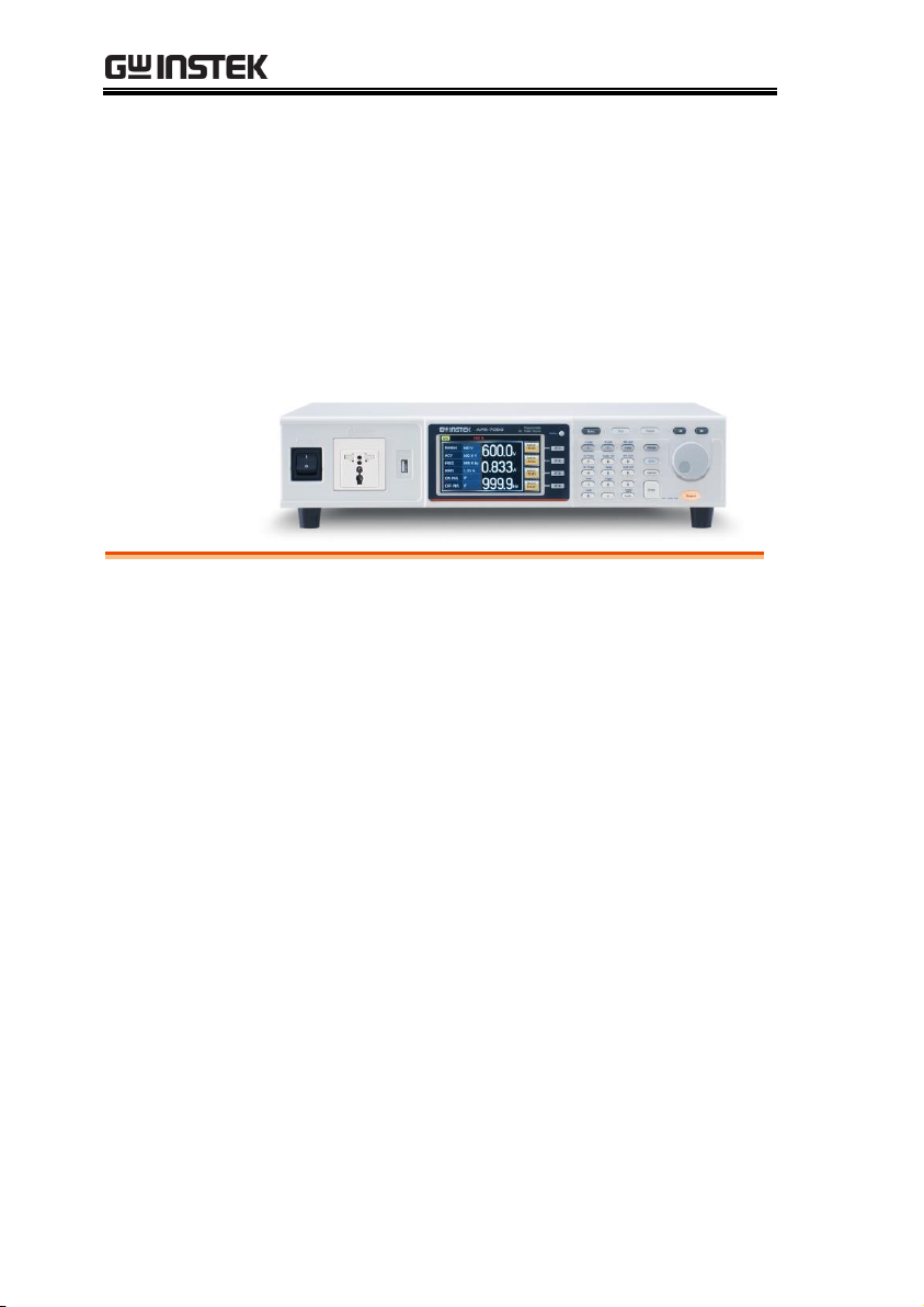
Programmable AC Power Source
APS-7000 Series
USER MANUAL
ISO-9001 CERTIFIED MANUFACTURER
Page 2

This manual contains proprietary information, which is protected by
copyright. All rights are reserved. No part of this manual may be
photocopied, reproduced or translated to another language without
prior written consent of Good Will company.
The information in this manual was correct at the time of printing.
However, Good Will continues to improve products and reserves the
rights to change specification, equipment, and maintenance
procedures at any time without notice.
Good Will Instrument Co., Ltd.
No. 7-1, Jhongsing Rd., Tucheng Dist., New Taipei City 236, Taiwan.
Page 3

Table of Contents
Table of Contents
SAFETY INSTRUCTIONS ................................................... 4
GETTING STARTED .......................................................... 8
APS-7000 Series Overview ...................... 9
Appearance .......................................... 14
OPERATION .................................................................. 26
Set Up .................................................. 28
Basic Operation ................................... 60
Advanced Settings ............................... 82
Miscellaneous ...................................... 88
Trigger ................................................. 95
Preset Settings ................................... 100
Arbitrary Waveform Function ............. 104
Test Mode Function ........................... 112
REAR PANEL SIGNAL OUTPUTS .................................... 149
COMMUNICATION INTERFACE .................................... 153
Interface Configuration ...................... 154
FAQ .............................................................................. 175
APPENDIX .................................................................... 177
Firmware Update ............................... 177
APS-7000 Default Settings ................. 179
APS-7000 Specifications ..................... 181
APS-7000 Dimensions ........................ 187
Declaration of Conform ity .................. 191
INDEX .......................................................................... 192
3
Page 4
APS-7000 Series User Manual
WARNING
Warning: Identifies conditions or practices that
could result in injury or loss of life.
CAUTION
Caution: Identifies conditions or practices that
could result in damage to the APS-7000 or to other
properties.
DANGER High Voltage
Attention Refer to the Manual
Protective Conductor Terminal
Earth (ground) Terminal
SAFETY INSTRUCTIONS
This chapter contains important safety
instructions that you must follow during
operation and storage. Read the following before
any operation to ensure your safety and to keep
the instrument in the best possible condition.
Safety Symbols
These safety symbols may appear in this manual or on the
instrument.
4
Page 5
SAFETY INSTRUCTIONS
Do not dispose electronic equipment as unsorted
municipal waste. Please use a separate collection
facility or contact the supplier from which this
instrument was purchased.
General
Guideline
CAUTION
Do not place any heavy object on the APS-7000.
Avoid severe impact or rough handling that
leads to damaging the APS-7000.
Do not discharge static electricity to the APS-
7000.
Use only mating connectors, not bare wires, for
the terminals.
Do not block the cooling fan opening.
Do not disassemble the APS-7000 unless you are
qualified.
(Measurement categories) EN 61010-1:2010 specifies the
measurement categories and their requirements as follows. The
APS-7000 doesn’t fall under category II, III or IV.
Measurement category IV is for measurement performed at the
source of low-voltage installation.
Measurement category III is for measurement performed in the
building installation.
Measurement category II is for measurement performed on the
circuits directly connected to the low voltage installation.
0 is for measurements performed on circuits not directly
connected to Mains.
Power Supply
WARNING
AC Input voltage range:
115/230 Vac ± 15% (APS-7050, APS-7100)
230 Vac ± 15% (APS-7200, APS-7300)
Frequency: 50/60Hz
To avoid electrical shock connect the protective
grounding conductor of the AC power cord to
an earth ground.
Safety Guidelines
5
Page 6
APS-7000 Series User Manual
Cleaning the APS7000
Disconnect the power cord before cleaning.
Use a soft cloth dampened in a solution of mild
detergent and water. Do not spray any liquid.
Do not use chemicals containing harsh material
such as benzene, toluene, xylene, and acetone.
Operation
Environment
Location: Indoor, no direct sunlight, dust free,
almost non-conductive pollution (Note below)
Relative Humidity: 20%~ 80%, no condensation
Altitude: < 2000m
Temperature: 0°C to 40°C
(Pollution Degree) EN 61010-1:2010 specifies the pollution degrees
and their requirements as follows. The APS-7000 falls under degree
2.
Pollution refers to “addition of foreign matter, solid, liquid, or
gaseous (ionized gases), that may produce a reduction of dielectric
strength or surface resistivity”.
Pollution degree 1: No pollution or only dry, non-conductive
pollution occurs. The pollution has no influence.
Pollution degree 2: Normally only non-conductive pollution
occurs. Occasionally, however, a temporary conductivity caused
by condensation must be expected.
Pollution degree 3: Conductive pollution occurs, or dry, non-
conductive pollution occurs which becomes conductive due to
condensation which is expected. In such conditions, equipment
is normally protected against exposure to direct sunlight,
precipitation, and full wind pressure, but neither temperature
nor humidity is controlled.
Storage
environment
Location: Indoor
Temperature: -10°C to 70°C
Relative Humidity: ≤80%, no condensation
Disposal
Do not dispose this instrument as unsorted
municipal waste. Please use a separate collection
facility or contact the supplier from which this
instrument was purchased. Please make sure
discarded electrical waste is properly recycled to
reduce environmental impact.
6
Page 7
SAFETY INSTRUCTIONS
Green/ Yellow:
Earth
Blue:
Neutral
Brown:
Live (Phase)
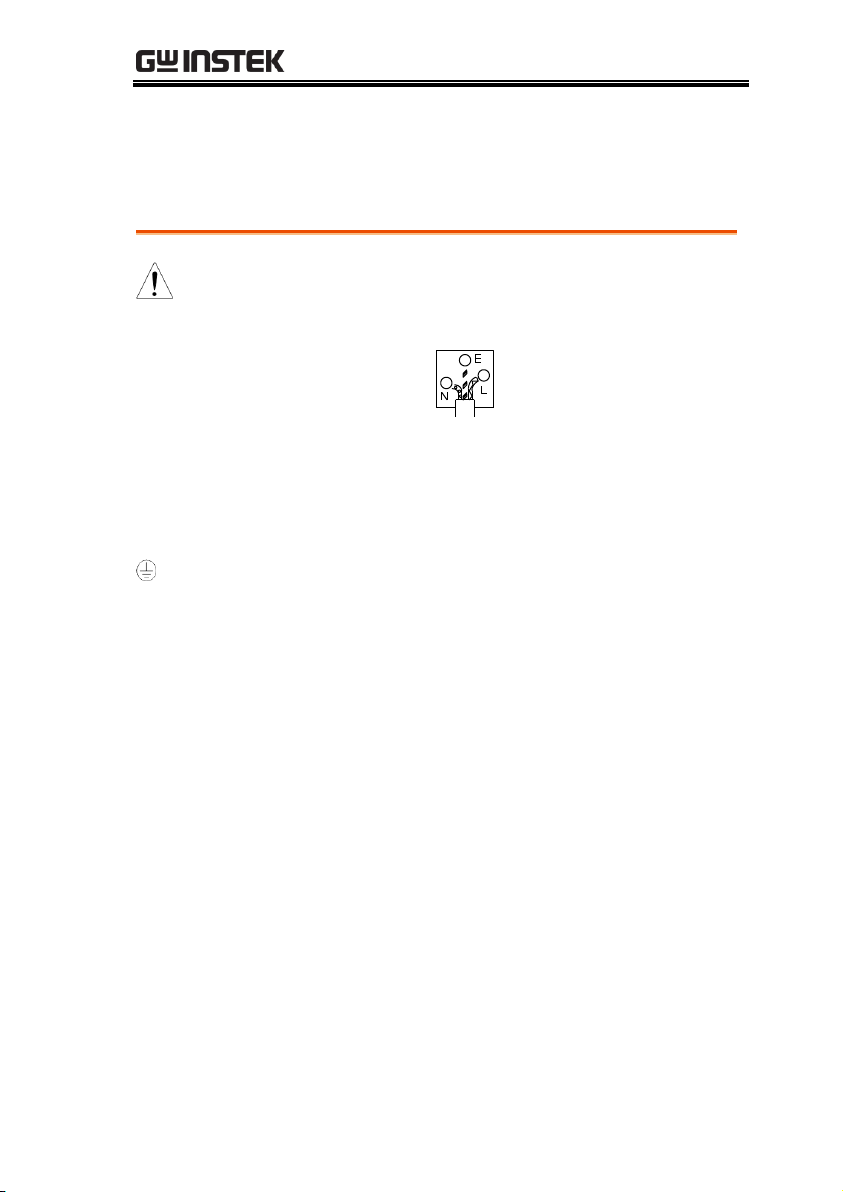
Power cord for the United Kingdom
When using the instrument in the United Kingdom, make sure the
power cord meets the following safety instructions.
NOTE: This lead/appliance must only be wired by competent persons
WARNING: THIS APPLIANCE MUST BE EARTHED
IMPORTANT: The wires in this lead are coloured in accordance with the
following code:
As the colours of the wires in main leads may not correspond with
the coloured marking identified in your plug/appliance, proceed
as follows:
The wire which is coloured Green & Yellow must be connected to
the Earth terminal marked with either the letter E, the earth symbol
or coloured Green/Green & Yellow.
The wire which is coloured Blue must be connected to the terminal
which is marked with the letter N or coloured Blue or Black.
The wire which is coloured Brown must be connected to the
terminal marked with the letter L or P or coloured Brown or Red.
If in doubt, consult the instructions provided with the equipment
or contact the supplier.
This cable/appliance should be protected by a suitably rated and
approved HBC mains fuse: refer to the rating information on the
equipment and/or user instructions for details. As a guide, a cable
of 0.75mm2 should be protected by a 3A or 5A fuse. Larger
conductors would normally require 13A types, depending on the
connection method used.
Any exposed wiring from a cable, plug or connection that is
engaged in a live socket is extremely hazardous. If a cable or plug is
deemed hazardous, turn off the mains power and remove the cable,
any fuses and fuse assemblies. All hazardous wiring must be
immediately destroyed and replaced in accordance to the above
standard.
7
Page 8
APS-7000 Series User Manual
APS-7000 Series Overview ......................................... 9
Series lineup ........................................................................................ 9
Operating Area ................................................................................... 9
Main Features ................................................................................... 11
Accessories ........................................................................................ 12
Appearance .............................................................. 14
Front Panel ........................................................................................ 14
Rear Panel .......................................................................................... 19
Status Bar Icons ................................................................................ 24
GETTING STARTED
This chapter describes the power source in a
nutshell, including its main features and front /
rear panel introduction.
8
Page 9
GETTING STARTED
Model name
Max. Output Current
Power Rating
Output Voltage
APS-7050
4.2A/2.1A
500VA
0~310.0 Vrms
APS-7100
8.4A/4.2A
1000VA
0~310.0 Vrms
APS-7200
16.8A/8.4A
2000VA
0~310.0 Vrms
APS-7300
25.2A/16.8A
3000VA
0~310.0 Vrms
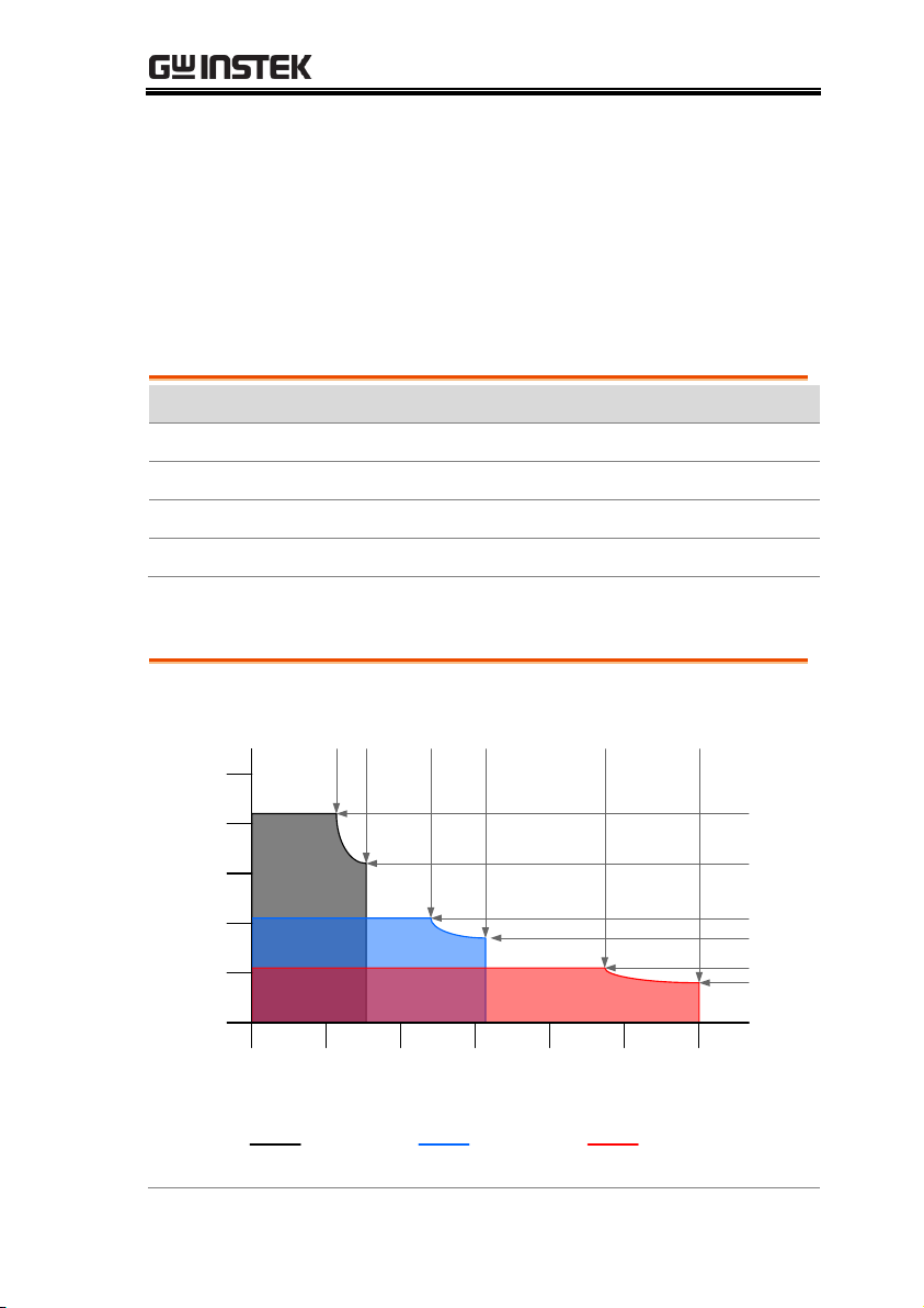
Voltage (V)
Current (A)
0
1
2
0
3
4
5
100
200
300
400 500
600
120 155 240
310 480
600
4.2
3.23
2.1
1.62
1.05
0.83
APS-7050 Output Operating Area
155V Range 310V Range 600V Range
(APS-003 Option)
APS-7000 Series Overview
Series lineup
The APS-7000 series consists of 4 models, the APS-7050, APS-7100,
APS-7200 and APS-7300, differing only in capacity. Note that
throughout the user manual, the term “APS-7000” refers to any of
the models, unless stated otherwise.
Operating Area
9
Page 10

APS-7000 Series User Manual
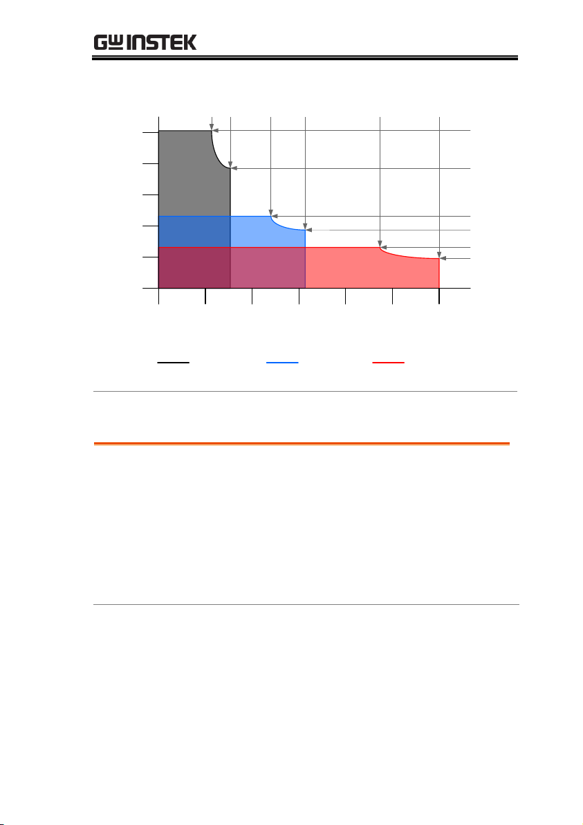
Voltage (V)
Current (A)
0
2
4
0
6
8
10
100
200
300
400 500
600
120 155 240
310 480
600
8.4
6.45
4.2
3.23
2.1
1.67
155V Range 310V Range 600V Range
APS-7100 Output Operating Area
(APS-003 Option )
Voltage (V)
Current (A)
0
5
10
0
15
20
100
200
300
400 500
600
120 155 240
310 480
600
16.8
12.9
8.4
6.45
4.2
3.33
155V Range 310V Range 600V Range
APS-7200 Output Operating Area
(APS-003 Option )
10
Page 11
Voltage (V)
Current (A)
0
5
10
0
15
20
25
100
200
300
400 500
600
120 155 240
310 480
600
25.2
19.4
12.6
9.7
6.3
5.0
155V Range 310V Range 600V Range
APS-7300 Output Operating Area
(APS-003 Option )
Main Features
Performance
Low output ripple and noise
Excellent and feature-rich measurement
capacity
Standard maximum output voltage is 310Vrms
Maximum output voltage and frequency of
600Vrms(APS-003 Option)/1000Hz(APS-004
Option)
GETTING STARTED
11
Page 12

APS-7000 Series User Manual
Features
OCP, OPP and OTP protection
Variable voltage, frequency and current limiter
Sequence and simulation function
Large 4.3 inch TFT panel
Globally adjustable power inlet not restricted by
the power supply environment
USB interface is equipped as standard with the
ability to save and recall setup files.
Only 88mm (2U) case height (APS-7050 and
APS-7100 models only).
Interface
Standard:
Ethernet port
USB host
USB CDC (APS-7200 and APS-7300 models
only)
Optional:
GPIB
RS-232 / USB CDC (APS-7050 and APS-7100
models only)
RS-232 (APS-7200 and APS-7300 models only)
Standard
Accessories
Part number
Description
CD ROM
User manual,
programming manual
82GW1SAFE0M*1
Safety guide
Region dependent
Type I Power cord
(APS-7050)
Region dependent
Type II Power cord
(APS-7100)
Accessories
12
Page 13

GETTING STARTED
Region dependent
Type III Power cord
(APS-7200, APS-7300)
62PS-7K0SC701 x1
5302-01613001 x1
Mains terminal cover set
(APS-7050)
62PS-7K0SC401 x1
5302-01613001 x2
Mains terminal cover set
(APS-7100)
GTL-123
Test leads: 1x red, 1x black
Optional
Capacity
Part number
Description
APS-003
Output Voltage Capacity:
0 ~ 600Vrms
APS-004
Output Frequency Capacity:
45 ~ 1000Hz
Optional
Accessories
Part number
Description
GRA-423
APS-7050 and APS-7100
rack mount kit
GRA-429
APS-7200 rack mount kit
GRA-430
APS-7300 rack mount kit
APS-001
GPIB interface card
APS-002
RS-232 / USB CDC
interface card (APS-7050
and APS-7100 only)
APS-007
RS-232 interface card (APS7200 and APS-7300 only)
GPW-004
Power Cord 8mm2/3C, 3m
Max Length, 105°C,
RNYBS8-6*3P, RNYB88*3P
Download
Name
Description
gw_aps.inf
USB driver
13
Page 14
APS-7000 Series User Manual
APS-7050
AC Power Source
Display
Programmable
F 1
F 2
F 3
F 4
Output
: Long Push
Menu Test Preset
V
Local
Off Phase
On Phase
0
1
4
7
2
5
8
3
6
9
V-Limit F-Limit IPK-Limit
F I rms
Cancel
Shift
Range
Enter
Lock
ALM CLR
IPK CLR
Unlock
Surge / Dip
Ramp
TriggerARB
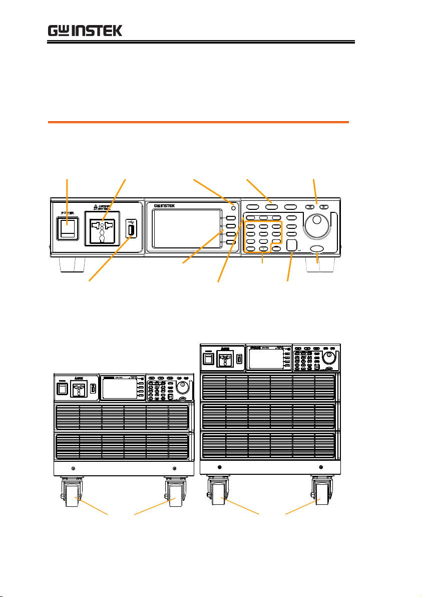
USB A port
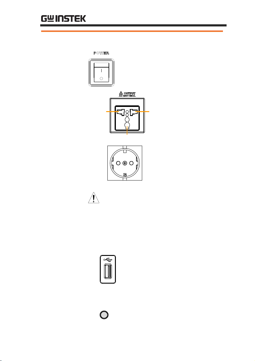
Power
switch
Front voltage
output socket
Menu, Test,
Preset keys
LCD
display
Function keys
Display
mode key
Arrow keys,
Scroll wheel
Voltage, Frequency,
Current setting and limit
Keypad
Range, Shift, Cancel,
Enter, Lock keys
Output key
Caster
Adjuster
foot
Caster
Appearance
Front Panel
APS-7050, APS-7100
APS-7200 APS-7300
14
Page 15
GETTING STARTED
Item
Description
Power Switch
Turns on the mains power.
Front Voltage
Output Socket
Neutral
GND
Line
Output voltage
terminal using a
regional universal
plug. There is a Euro
and a Universal
regional plug.
CAUTION
Maximum allowable output voltage
and current are 250Vrms and
15Arms.
For voltages exceeding 250Vrms or
current over 15Arms, please use the
rear output terminal.
Universal and EURO region plugs
socket must be factory installed.
USB A Port
The USB port is used for data
transfers and upgrading software.
LCD Screen
Displays the measured values or
menu system.
Display Mode
Select Key
Display
Selects between Standard mode
and Simple mode.
15
Page 16
APS-7000 Series User Manual
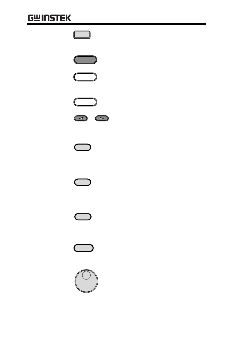
Function Keys
F 1
Assigned to the functions
displayed on the right-hand side
of the screen.
Menu Key
Menu
Enters the Main menu or goes
back to one of the display modes.
Test Key
Test
Puts the instrument into the
Sequence, Simulation and
Program Control mode.
Preset Key
Preset
Puts the instrument into Preset
mode.
Arrow Keys
The arrow keys are used to select
the digit power of a value that is
being edited.
V
V
V-Limit
Used for setting the output
voltage.
V-Limit
(Shift + V)
Used for setting the output voltage
limit value.
F
F
F-Limit
Used for setting the output
frequency.
F-Limit
(Shift + F)
Used for setting the output
frequency limit value.
I rms
I rms
IPK-Limit
Used for setting the maximum
output current.
IPK-Limit
(Shift + I rms)
Used to set the peak output
current limit value.
Range Key
Range
Switches between the 155V, 310V
and 600V ranges (the 600V range
is an option).
Scroll Wheel
Used to navigate menu items or
for incrementing/decrementing
values one step at a time.
16
Page 17
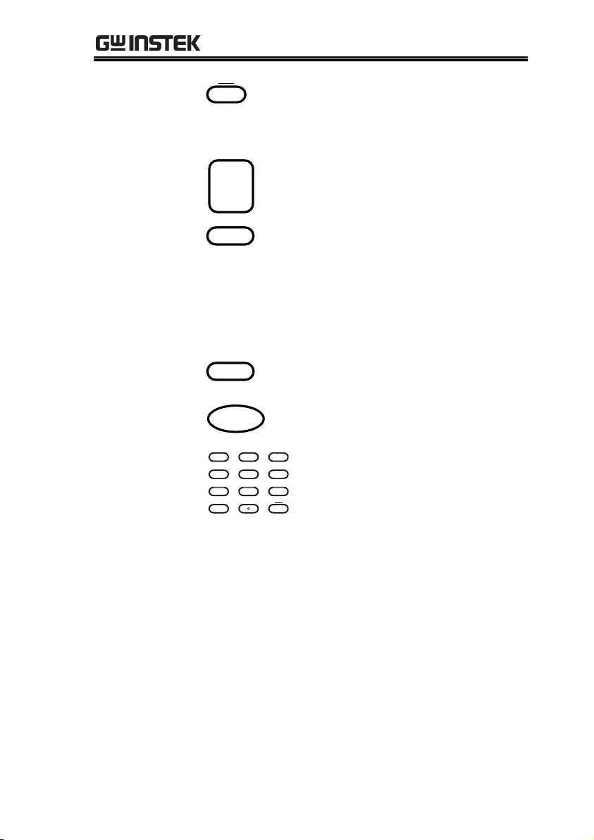
GETTING STARTED
Lock Key
Lock
Unlock
Locks the number pad to prevent
accidentally changing panel
settings.
Unlock Key
(Long press)
Disables the key lock.
Enter Key
Enter
Confirms selections / settings
Cancel Key
Cancel
Clears entries that are made in the
number entry dialog when a value
is edited using the arrow keys or
the scroll wheel.
The Cancel key can also be used to
cancel function setting menus or
dialogs.
Shift Key
Shift
Turns on the shift state, which
enables shortcut operations.
Output Key
Output
Turns the output on or off.
Number Pad
0
142
5
8
3
6
9
Lock
Unlock
7
On Phase Surge / Dip IPK CLR
Off Phase Ramp ALM CLR
ARB Trigger
Local
Used to enter values.
Local Mode
(Shift + 0)
Switches operation back to local
mode from remote mode.
ARB Mode
(Shift + 1)
Sets the ARB function.
Trigger Mode
(Shift + 2)
Sets the JI port trigger behavior on
the rear panel.
Off Phase
(Shift + 4)
Sets the off phase for the output
voltage.
RAMP
(Shift + 5)
Quick settings for Ramp control.
ALM CLR
(Shift + 6)
Clears alarms.
On Phase
(Shift + 7)
Sets the on phase for the output
voltage.
17
Page 18

APS-7000 Series User Manual
Surge/Dip
(Shift + 8)
Quick settings for Surge/Dip
control.
IPK CLR
(Shift + 9)
Clears peak current hold.
18
Page 19
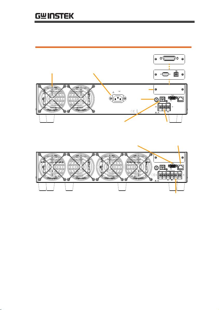
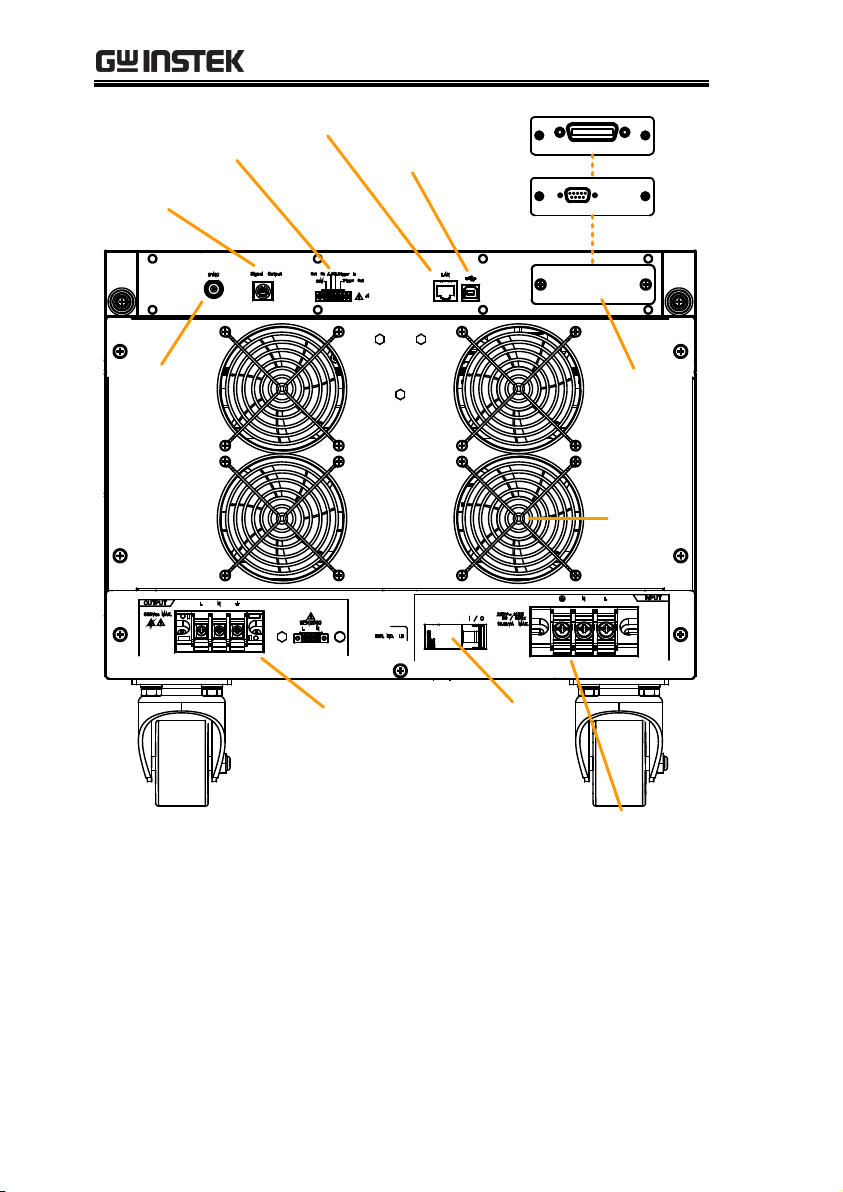
Rear Panel
SYNC
Signal Output LAN
OUTPUT INPUT
L N N L
600Vac MAX. 115 / 230V 15%
50 / 60Hz
3.6kVA MAX.
Out On / Off
COM
J1
Trigger Out
Trigger In
115 / 230V 15%
50 / 60Hz
1.8kVA MAX.
SYNC
SER. NO. LB
L N
600Vac MAX.
Signal Output
Trigger Out
Trigger In Out On / Off
COM
LAN
J1
OUTPUT
Fan
GPIB
Line voltage input
GPIB
RS232
RS-232/
USB Device
Sync
Signal Output Rear panel voltage
output terminal
Remote control Ethernet port
Line voltage input
APS-7050
APS-7100
Opt. int. port
GETTING STARTED
19
Page 20
APS-7000 Series User Manual
Remote control
Ethernet port
Line voltage input
APS-7200
GPIB
GPIB
RS232
RS-232
Fan
Sync
Signal Output
Rear panel voltage
output and
sensing terminals
Optional
interface
port
Circuit
breaker
(current)
USB port
20
Page 21

Remote control
Ethernet port
Line voltage input
APS-7300
GPIB
GPIB
RS232
RS-232
Fan
Sync
Signal Output
Rear panel voltage
output and
sensing terminals
Optional
interface
port
Circuit
breaker
(current)
USB port
GETTING STARTED
21
Page 22
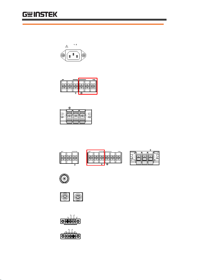
APS-7000 Series User Manual
Line Voltage
Input
APS-7050
115 / 230V 15%
50 / 60Hz
1.8kVA MAX.
Voltage Input: 115/230±15% VAC;
Line frequency: 50Hz/60 Hz
(Automatically switchable)
APS-7100
OUTPUT INPUT
L N N L
Voltage Input: 115/230±15%
VAC ; Line frequency:
50Hz/60 Hz (Automatically
switchable)
APS-7200 & 7300
N L
Voltage Input: 230±15% VAC ;
Line frequency: 50Hz/60 Hz
Rear Voltage
Output Socket
Output voltage terminal.
APS-7050
L N
OUTPUT
APS-7100
OUTPUT INPUT
L N N L
APS-7200 & 7300
L N
Sync Output
Socket
SYNC
BNC socket. This socket will output a
signal of approximately 10V when the
output is on.
Signal Output
Signal output
APS-7050
APS-7100
APS-7200
APS-7300
Connector for monitoring PASS, FAIL
and PROCESSING output signals
when using the Program mode.
Remote Control
Trigger Out
Trigger In
Out On / Off
COM
APS-7200 and APS-7300
Trigger Out
Trigger In Out On / Off
COM
APS-7050 and APS-7100
Connector for controlling the
TRIGGER IN, TRIGGER OUT and
OUT ON/OFF states.
22
Page 23
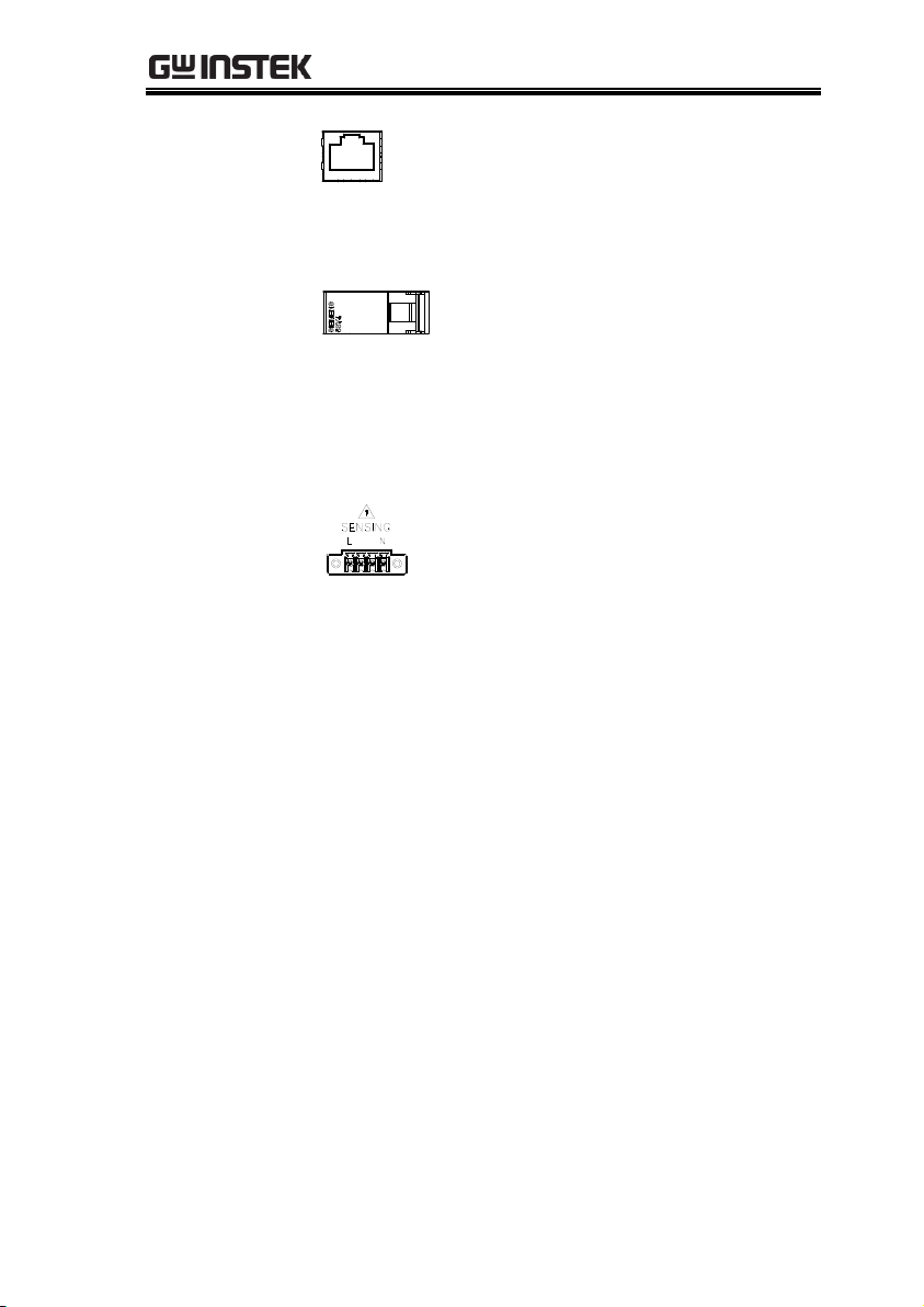
GETTING STARTED
Ethernet Port
LAN
The Ethernet port is used for remote
control and digital monitoring from a
PC.
Optional
Interface Slot
Optional GPIB communication, RS-232/USB B
communication and RS-232 communication.
Circuit breaker
(APS-7200,
APS-7300 only)
I / O
Main power circuit (current) breaker
Rating : 40A (APS-7200)
63A (APS-7300)
Note: Check the status of the power
breaker before power-on the APS-7200
or APS-7300.
FAN
Temperature controlled fan.
Remote sense
(APS-7200,
APS-7300 only)
Compensation of the load wire drop.
23
Page 24
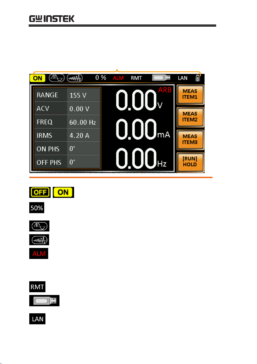
APS-7000 Series User Manual
Status bar
ARB
/
Indicates if the output is ON or OFF.
Indicates the output power as a percentage of full
scale.
Indicates that the Surge/Dip function is active.
Indicates that the Ramp function is active.
The alarm icon will appear on the status bar
when one of the protection functions are tripped.
Applies to Over Power, Over Irms, Over Ipeak
and Over Temperature protection.
Indicates that the APS-7000 is in remote mode.
Indicates that a USB drive is detected in the front
panel host port.
Indicates that the LAN interface is activated.
Status Bar Icons
24
Page 25

GETTING STARTED
Indicates that the panel lock is active.
ARB
Indicates that the ARB function is active.
25
Page 26

APS-7000 Series User Manual
Set Up ..................................................................... 28
Line Voltage Removal and Installation for APS-7100 .............. 28
Filter Installation .............................................................................. 31
Power Up ........................................................................................... 33
Output Terminals ............................................................................. 34
Wire gauge considerations .............................................................. 39
Installing the Optional Hardware Modules ................................. 41
Installing Optional Software Modules .......................................... 43
Using the Rack Mount Kit ............................................................. 48
How to Use the Instrument ........................................................... 50
Reset to Default Settings ................................................................ 54
View System Version and Serial Number .................................... 55
LCD Configuration.......................................................................... 56
USB Driver Installation .................................................................. 57
Basic Operation ....................................................... 60
Setting the Voltage Range ............................................................... 60
Setting the Voltage Limit ................................................................ 61
Setting the Output Voltage............................................................. 62
Setting the Frequency Limit ........................................................... 64
Setting the Output Frequency........................................................ 65
Setting the Peak Current Limit ...................................................... 66
Setting the Current RMS Level ...................................................... 70
Setting the On/Off Phase .............................................................. 73
Alarm Clear ....................................................................................... 74
Display Modes .................................................................................. 75
Panel Lock ......................................................................................... 77
Turning the Output On .................................................................. 78
Using the remote sense (APS-7200 and APS-7300 only) ......... 79
Local Sense ........................................................................... 79
Remote Sense ...................................................................... 80
Advanced Settings ................................................... 82
Surge/Dip Control .......................................................................... 82
Ramp Control ................................................................................... 85
Miscellaneous.......................................................... 88
OPERATION
26
Page 27

OPERATION
T Ipeak, hold..................................................................................... 88
Power ON Output ........................................................................... 90
Buzzer ................................................................................................ 91
SCPI Emulation ............................................................................... 92
Remote Sense (APS-7200 and APS-7300 only) .......................... 93
Trigger ..................................................................... 95
Trigger Control Settings ................................................................. 95
Preset Settings .......................................................100
Save Preset Settings to Local Memory ....................................... 100
Load Preset Settings to Local Memory ...................................... 101
Manage Preset Settings ................................................................. 102
Arbitrary Waveform Function ..................................104
ARB Mode Overview .................................................................... 105
Selecting an ARB Waveform ....................................................... 109
Test Mode Function ................................................112
Simulate Mode Overview ............................................................. 114
Simulate Settings ............................................................................ 118
Save a Simulation to Local Memory ........................................... 121
Recall a Simulation from Local Memory ................................... 121
Manage Simulation Settings ......................................................... 122
Running a Simulation .................................................................... 124
Sequence Mode Overview ............................................................ 126
Sequence Settings ........................................................................... 130
Save a Sequence to Local Memory ............................................. 134
Recall a Sequence from Local Memory...................................... 134
Manage Sequence Settings ............................................................ 135
Running a Sequence ...................................................................... 137
Program Mode Overview ............................................................. 139
Save a Program to Local Memory............................................... 146
Recall a Program from Local Memory ....................................... 146
Manage Program Settings ............................................................. 147
27
Page 28
APS-7000 Series User Manual
Background
The APS-7100 is equipped with an input power
terminal that can accept 115V/230V ± 15%. To
connect or replace the power cord (GW Instek
part number 4300-31000101), use the procedure
below:
Warning
The following procedure should only be attempted
by competent persons.
Ensure the AC power cord is not connected to
power.
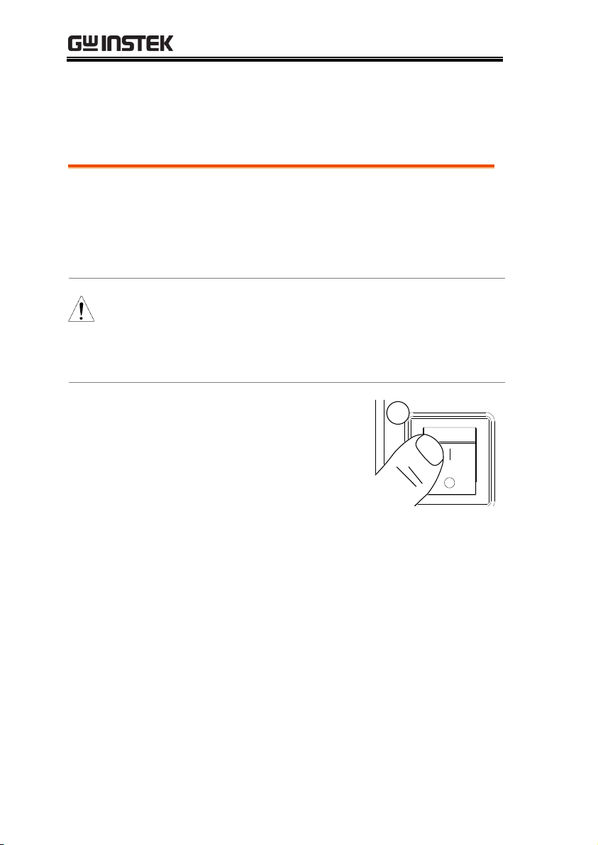
Removal
1. Turn off the power
switch.
1
APS-7100
2. Unscrew the power cord protective sheath on
the rear output socket.
3. Remove the 2 screws holding the power cord
cover and remove.
Set Up
Line Voltage Removal and Installation for APS-7100
28
Page 29
OPERATION
APS-7100
3
2
4. Remove the AC
power cord wires.
4
CAUTION
The power line inputs for the APS-7100 are on the
outer cluster of terminals.
The terminals to the inner of the panel are the rear
panel outputs.
Installation
1. Connect the AC power cord wires to the AC
input terminals.
White/Blue Neutral (N)
Green/Green-yellowGND ( )
Black/Brown Line (L)
29
Page 30
APS-7000 Series User Manual
APS-7100
OUTPUT INPUT
L N N L
115 / 230V 15%
Line
Neutral
Ground
2. Re-install the power cord cover.
3. Screw the power cord sheath back onto the
cover.
APS-7100
2
3
30
Page 31

Background
The APS-7200/7300 has a filter (GW Instek part
number, 57RG-30B01801) that must first be
inserted under the control panel before
operation.
Steps
1. Pull outward as indicated
in the arrow to detach the
snap.
See below
for details
2. Remove the cover
3. Remove the screws
4. Move the plastic frame in
the direction indicated by
the arrow
OPERATION
Filter Installation
31
Page 32

APS-7000 Series User Manual
5. Remove the plastic frame.
6. Replace the filter with a
new one.
7. The unit is now ready to power up.
Note
Please clean regularly to avoid damaging the
internal components of the machine
Warning
The following procedure should only be attempted
by competent persons.
Ensure the AC power cord is not connected to
power.
32
Page 33

Power Up
Steps
1. Socket type (APS-7050):
Connect the power cord
to the rear panel socket.
Input Power Terminal
(APS-7100, 7200 & 7300):
Connect the power cord to
the input power terminals.
APS-7200 & 7300,
see page 22,
APS-7100,
see page 28.
2. Press the POWER key. The splash screen will
appear momentarily before the continuous
mode screen appears with the settings loaded.
CAUTION
The power supply takes around 10 seconds to fully
turn on and shutdown.
Do not turn the power on and off quickly.
OPERATION
33
Page 34

APS-7000 Series User Manual
Background
The output terminals can be output from either
the front panel or from the rear panel. The
outputs are limited to 4.2A/2.1A (APS-7050),
8.4A/4.2A (APS-7100), 16.8A/8.4A (APS-7200)
or 25.2A/12.6A (APS-7300).
Supported plugs
Multi-region terminal Socket
Supported Standards
IEC, North America, Japan.
EURO CEE type universal plug
WARNING
Dangerous voltages. Ensure that the power to the
instrument is disabled before handling the power
supply output terminals. Failing to do so may lead
to electric shock.
CAUTION
For the front panel output, the maximum output
voltage is 250VAC and current is 10A.
Front Panel
Output
Connection
1. The front panel has a multi-region power
socket depending on the socket type.
2. Insert the plug from the DUT into the socket.
(APS-7050 or APS7100 shown)
EURO CEE socket
IEC North America, Japan
Output Terminals
34
Page 35

OPERATION
WARNING
Dangerous voltages. Ensure the output is off
before unplugging the plug from the front panel
socket.
3. Turn the power on. The AC power supply is
now ready to power the DUT.
Rear Panel Output
Connection
The rear panel output is used to supply higher
power DUTs. The rear panel output connection
is similar to the universal rear panel line input
connection on the APS-7100, APS-7200 or APS-
7300.
1. Disconnect the unit from the mains power
socket and turn the power switch off.
2. Unscrew the power cord protective sheath
(APS-7050 and APS-7100).
3. Remove the 2 screws holding the power cord
cover and remove (APS-7050 and APS-7100).
APS-7050
3
2
35
Page 36

APS-7000 Series User Manual
APS-7100
3
2
CAUTION
For the APS-7100, there is a single bank for the
input and output terminals. Ensure the correct
terminals are connected. The APS-7050, APS-7200
and APS-7300 have a dedicated bank of output
terminals on the rear panel.
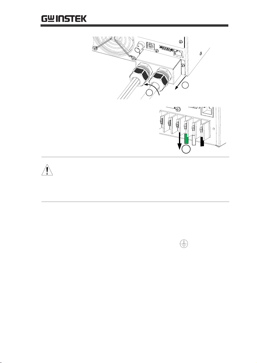
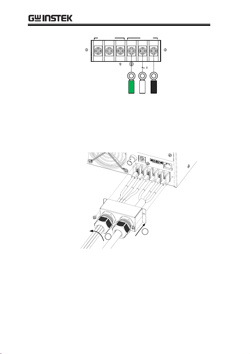
Installation
4. Connect the output AC power cord wires to
the AC output terminals.
Black Neutral (N)
Green GND ( )
Red Line (L)
APS-7100
OUTPUT INPUT
L N N L
115 / 230V 15%
Line
Neutral
Ground
Ground
Neutral
Line
APS-7100 shown. The input terminals are already
connected and shows which output terminals are
to be connected.
36
Page 37

OPERATION
APS-7050, APS7200 and APS7300
Line
Neutral
Ground
L N
OUTPUT
APS-7050 shown.
5. Re-install the power cord cover (APS-7050
and APS-7100).
6. Screw the power cord sheath back onto the
cover (APS-7050 and APS-7100).
APS-7050
5
6
37
Page 38

APS-7000 Series User Manual
APS-7100
5
6
7. Turn the power on. The AC power supply is
now ready to power the DUT.
Note
Grounded Neutral Output:
APS-7000 allows for a grounded return on the neutral
output.
It is suit for the medical industry that required
between ground with neutral is 0V essentially.
And possible to mitigate ground loops that is ideal for
reduce ground noise and isolate sensitive equipment
from the effects of ground loops.
WARNING
Because the neutral has been referenced to the
chassis ground, be careful electric shock by yourself.
38
Page 39

OPERATION
Background
Before connecting the output terminals to a
load, the wire gauge of the cables should be
considered.
It is essential that the current capacity of the
load cables is adequate. The rating of the cables
must equal or exceed the maximum current
rated output of the instrument.
Recommended
wire gauge
Wire Gauge
Nominal Cross
Section
Maximum Current
20
0.5 9
18
0.75
11 18
1
13 16
1.5
18 14
2.5
24 12
4
34 10
6
45
8 10
64
6 16
88 4
25
120 2
32
145 1
50
190 00
70
240 000
95
290 0000
120
340
The maximum temperature rise can only be 60
degrees above the ambient temperature. The
ambient temperature must be less than 30
degrees.
To minimize noise pickup or radiation, the
load wires and remote sense wires should be
twisted-pairs of the shortest possible length.
Shielding of the sense leads may be necessary
in high noise environments. Where shielding is
Wire gauge considerations
39
Page 40

APS-7000 Series User Manual
used, connect the shield to the chassis via the
rear panel ground screw. Even if noise is not a
concern, the load and remote sense wires
should be twisted-pairs to reduce coupling,
which might impact the stability of the power
supply. The sense leads should be separated
from the power leads.
40
Page 41

OPERATION
Background
There are a number of optional modules that
can be installed for remote control.
Optional Modules
APS-001
GPIB Interface card
APS-002
RS-232/USB CDC interface card
APS-007
RS-232 interface card
WARNING
Dangerous voltages. Ensure that the power to the
instrument is disabled before handling the power
supply output terminals. Failing to do so may lead
to electric shock.
CAUTION
Ensure the power is off before installing any of the
optional modules.
Installation
1. Turn off the power
switch.
1
2. Unscrew the two screws holding the options
panel plate.
2
APS-7100 shown
Installing the Optional Hardware Modules
41
Page 42

APS-7000 Series User Manual
3. Slide the module PCB onto the rails on the
inside of the module slot.
4. Secure the module with the screws that were
removed from step 2.
4
3
APS-7100 shown
5. The module will be recognized upon startup.
42
Page 43

OPERATION
Background
The APS-003 and APS-004 are optional software
modules that upgrade the voltage limit and
frequency limit to 600Vrms and 1000Hz,
respectively. Like the firmware, the software
modules can be upgraded using the USB A port
on the front panel. See your local distributor or
GW Instek to purchase these options.
WARNING
The APS-003 and APS-004 software module license
keys have been updated and there are now two
license key file formats in use:
- The old license keys were tied to the serial
number of the APS-7000 unit. The license key
files used XXXXXX.lis formatting, where
XXXXXX was the serial number of the unit the
license key is intended for.
- The new license keys are no longer tied to
serial numbers. These new license key files use
XXXXXX.lic formatting (APS003.lic &
APS004.lic). The new license keys can be
exported and transferred to different units.
The old and new license keys are to be used with
the following equipments and restrictions:
- Old license key (*.lis): can only be used with
the APS-7050 and the APS-7100 with a
firmware version below V1.08.
- New license key (*.lic): APS-7050 and APS-
7100 with a V1.08 firmware version or above;
any APS-7200; any APS-7300.
Note
To upgrade APS-003 or APS-004, it is recommended to
Installing Optional Software Modules
43
Page 44

APS-7000 Series User Manual
upgrade the software version to the latest one.
For software, please contact GW or local distributors.
OLD LICENCE KEY INSTALLATION (XXXXXX.LIS format)
Note
This installation guide only applies to APS-7050
and APS-7100 equipments with a firmware version
below V1.08.
These options require your serial number. The
older license keys are not longer available for
purchase.
The serial number on the APS unit must match the
XXXXXXX.lis filename, or the upgrade will fail.
See page 55 for instructions on how to view your
serial number
Steps
1. Insert the USB flash drive into the USB port on
front panel of the APS-7000.
The USB drive should include the
XXXXXX.lis file in a directory named
“gw”(USB\gw:).
2. Press the Menu key. The Menu
setting will appear on the display.
Menu
3. Use the scroll wheel to go to item 11, Special
Function and press Enter.
4. Key in the password when prompted and then
press Enter.
The password is “5004”.
5. Go to Item 5, Add New Module and press Enter.
44
Page 45

OPERATION
6. If the upgrade is successful, “Vlimit Enabled”
or “Flimit Enabled” will appear on the screen.
Vlimit option successfully upgraded
Invalid License
7. If the upgrade is not successful, “Invalid
License” will be displayed. Check to make
sure the serial number and the XXXXXX.lis
filename match.
NEW LICENCE KEY INSTALLATION (XXXXXX.LIC format)
Note
This installation guide only applies to firmware
versions 1.08 or above on APS-7050, APS-7100,
APS-7200 and APS-7300 equipments. Do not
attempt this installation procedure with older
firmware.
The license keys (APS003.lic & APS004.lic), can be
exported and transferred to another APS-7000
power supply of the same model at anytime. A
license key can only be used with one machine at a
time.
Steps
1. Insert the USB flash drive into the USB port on
front panel of the APS-7000.
The USB drive should include the APS003.lic
or APS004.lic file in a directory named
“gw”(USB\gw:).
2. Press the Menu key. The Menu
setting will appear on the display.
Menu
45
Page 46

APS-7000 Series User Manual
3. Use the scroll wheel to go to item 11, Special
Function and press Enter.
4. Key in the password when prompted and then
press Enter.
The password is “5004”.
5. Go to Item 5, Add New Module and press Enter.
6. If the upgrade is successful, “Vlimit Enabled”
or “Flimit Enabled” will appear on the screen.
7. Reset the power to the unit when prompted.
Invalid License
8. If the upgrade is not successful, “Invalid
License” will be displayed.
NEW LICENCE KEY EXPORT (XXXXXX.LIC format)
Note
This guide will EXPORT the license key back to the
USB flash drive* so that the license key can be
installed on a different unit.
*The same USB flash drive that originally
contained the *.lic license key must be used when
exporting the license key.
Steps
1. Insert the USB flash drive into the USB port on
front panel of the APS-7000.
46
Page 47

OPERATION
2. Press the Menu key. The Menu
setting will appear on the display.
Menu
3. Use the scroll wheel to go to item 11, Special
Function and press Enter.
4. Key in the password when prompted and then
press Enter.
The password is “5004”.
5. Press F1 Export APS-003 or F2 Export APS-004.
6. Reset the power to the unit when prompted.
7. The APS003.lic or APS004.lic will now be in
the GW directory of the USB flash drive.
Warning
You can only export one license key at a time.
You cannot have two license keys on the same USB
drive.
You cannot copy a license key to another USB
drive. Trying to do so will cause the file to be lost or
to be mismatched.
47
Page 48

APS-7000 Series User Manual
Background
The APS-7050, APS-7100, APS-7200 and
APS7300 have optional Rack Mount kits:
Model
Rack Mount kit part
number
APS-7050 & 7100
GRA-423
APS-7200
GRA-429
APS-7300
GRA-430
The APS-7050 and APS-7100 are designed to fit
into a 2U rack height. The APS-7200 is
designed to fit into a 7U rack height. The APS7300 is designed to fit into a 9U rack height.
Please see your distributor for further rack
mount details.
Rack mount
diagram (APS7050 or 7100)
Using the Rack Mount Kit
48
Page 49

OPERATION
Rack mount
diagram (APS-
7200)
Rack mount
diagram (APS-
7300)
CAUTION
Ensure adequate ventilation is provided when
using the rack mount. Ensure at a gap of at least
50mm is given for the side air intakes. Failure to
do so may cause the instrument to overheat.
49
Page 50

APS-7000 Series User Manual
Background
The APS-7000 AC power supplies generally
use the scroll wheel, arrow keys and Enter keys
to edit numerical values or to select menu
options.
Menu navigation is performed using the menu
keys and function keys on the front panel.
The following section will explain some of
these concepts in detail.
Selecting Menu
Items
1. Turn the scroll wheel to select
parameters in menus and lists.
The selected parameter will be
highlighted in orange. The scroll
wheel is also used to
increment/decrement setting
values.
2. Press the Enter key to edit the
parameter or to enter the selected
menu.
Enter
How to Use the Instrument
50
Page 51

OPERATION
Example
Selected parameter
The following is an example of the menu list that
appears when the Menu key is pressed.
Using the Keypad
to edit parameter
values
When editing a value the keypad can be used
to directly enter the desired value.
1. Type the value of the
parameter using the
keypad.
0
1
4
2
5
8
3
6
9
Lock
Unlock
7
On Phase Surge / Dip IPK CLR
Off Phase Ramp ALM CLR
ARB Trigger
Local
2. Press the Enter key to confirm the
edit.
Enter
Example
Parameter
51
Page 52

APS-7000 Series User Manual
Using the Arrow
Keys and Scroll
wheel to edit
parameter values
Use the arrow keys to select a digit power and
then use the scroll wheel to edit the value by
that power.
1. Use the arrow keys to move the
cursor to the digit of the desired
power.
2. Turn the scroll wheel to edit the
value by the resolution of the
selected digit.
Cursor
3. Repeat the steps above for all the relevant
digits.
4. Press the Enter key to confirm the
edit.
Enter
Note
By default the cursor starts at the lowest power
digit.
52
Page 53

OPERATION
Using the
onscreen
keyboard
The onscreen keyboard is only used in the
Program Mode. The screenshot below is an
example of the onscreen keyboard.
On screen keyboard
Entered characters
Using the
Function Keys
The function keys are quick settings keys, the
function of which depends on the current
menu or operation.
1. Press the function key that corresponds to the
setting directly to its left.
2. The setting or parameter is immediately
executed.
Function keys
APS-7050
AC Power Source
Display
Programmable
Output
: Long Push
Menu Test Preset
V
Local
Off Phase
On Phase
0
1
4
7
2
5
8
3
6
9
V-Limit F-Limit IPK-Limit
F I rms
Cancel
Shift
Range
Enter
Lock
ALM CLR
IPK CLR
Unlock
Surge / Dip
Ramp
TriggerARB
F 1
F2
F3
F4
Corresponding quick
settings
3. Repeat the steps above for all the relevant
digits.
53
Page 54

APS-7000 Series User Manual
Background
The default settings can be restored from the
Menu key settings. See page 179 for the default
factory settings.
Steps
1. Press the Menu key. The Menu
settings will appear on the
display.
Menu
2. Use the scroll wheel to go to item 10, Default
Setting.
3. Press Enter x2 to restore the default settings.
Default settings
Reset to Default Settings
54
Page 55

OPERATION
Background
The Menu>System Information setting
displays the serial number and version
number.
Steps
1. Press the Menu key. The Menu
setting will appear on the display.
Menu
2. The system information should now be listed
on the display.
If not, use the scroll wheel to go to item 1,
System Information.
System
Information
View System Version and Serial Number
55
Page 56

APS-7000 Series User Manual
Background
The LCD Configuration setting sets the
brightness, contrast and saturation level of the
LCD display.
Steps
1. Press the Menu key. The Menu
settings will appear on the
display.
Menu
2. Use the scroll wheel to go to item 9, LCD
Configuration and press Enter.
3. Set the brightness, contrast and saturation.
Contrast(%)
1 ~ 100% (Default=50%)
Brightness(%)
1 ~ 100% (Default=50%)
Saturation(%)
1 ~ 100% (Default=50%)
Exit
4. Press Exit[F4] to exit from the
Ramp Control settings.
Default Settings
5. Press Default[F3] to set all the LCD settings to
50%.
LCD settings
Default
settings
LCD Configuration
56
Page 57

OPERATION
Background
If the USB Type B interface is to be used for
remote control, the USB driver needs to be
installed.
Note
The USB driver, GW_APS.inf, is located on the
CD Rom that accompanied this user manual.
Alternatively the driver can be downloaded
from the GW Instek website.
For information on the USB interface, see page
154.
Steps
1. Connect the rear panel USB -B port on the
APS-7000 to the PC using a USB Type A to B
cable.
2. Go the Windows Device Manager.
For Windows 7:
Start > Control Panel > Hardware and Sound
> Device Manager
USB Driver Installation
57
Page 58

APS-7000 Series User Manual
3. The APS-7000 will be located under Other
Devices in the hardware tree. Right-click the
APS-7XXX and choose Update Driver Software.
4. From the hardware wizard choose Browse my
computer driver software.
58
Page 59

OPERATION
5. Set the file path to the location of the USB
driver, click Next and finish the driver
installation.
6. In APS-7000 will now be located in the Ports
node of the hardware tree in the Windows
Device Manager if the driver installation was
successful.
59
Page 60

APS-7000 Series User Manual
Background
The Range setting determines the general outlet
voltage range. The ranges available correspond
to common mains output voltage standards.
Steps
1. Press Range to access the Range
menu.
Range
Basic Operation
This section describes the basic operations required to operate the
power supply.
Setting the Voltage Range → from page 60
Setting the Voltage Limit → from page 61
Setting the Output Voltage → from page 62
Setting the Frequency Limit → page 64
Setting the Output Frequency → page 65
Setting the Peak Current Limit → from page 66
Setting the Current RMS Level → from page 68
Setting the On/Off Phase → from page 73
Clearing the Alarm → from page 74
Setting the Display mode → from page 75
Panel lock → from page 77
Turning the Output on/off → from page 78
Using the remote sense (APS-7200, APS-7300) → from page 79
Before operating the power supply, please see the Getting Started
chapter, page 8.
Setting the Voltage Range
60
Page 61

OPERATION
2. Set the voltage range with the scroll wheel or
with the F1 ~ F4 soft-keys.
Range
AUTO, 600V(option), 310V, 155V
Soft-keys
AUTO, 600V(option), 310V, 155V
3. Press Enter to confirm the Range setting.
Range setting
Soft-key
settings
F1
F2
F3
F4
Note
If the range is changed from 155V to 600V, the
Irms and IPK values will automatically be changed
to a lower value. If the range is changed from 600V
to 155V, the Irms and IPK values remain the same.
If the voltage range is changed when the output is
on, the output will be automatically turned off.
Background
Setting the voltage limit allows the output
voltage to be set to any level within the voltage
limit (V Limit) range.
Steps
1. Press Shift + V to access the Volt
Limit menu.
Shift
+
V
V-Limit
Setting the Voltage Limit
61
Page 62

APS-7000 Series User Manual
2. Set the voltage limit with the scroll wheel or
with the F3 ~ F4 soft-keys. The MAX and MIN
soft-keys set the limit to the maximum and
minimum, respectively.
Range
10% of full range ~ full range
Soft-keys
MAX, MIN
3. Press Enter to confirm the voltage limit setting.
Volt Limit
Min/Max
settings
F3
F4
Note
Each voltage range (155V, 310V, 600V) has an
independent voltage limit.
Before change volt limit setting, if ACV setting
value is bigger than desire volt limit value, so that
the volt limit value can't be change.
Background
Before setting the power supply voltage level,
set the voltage range and voltage limit.
Steps
1. Press the V key. The ACV
parameter will be editable.
V
V-Limit
2. Set the voltage with the scroll wheel/keypad
or with the F1 ~ F4 soft-keys.
Setting the Output Voltage
The voltage setting sets the voltage level of the power supply.
62
Page 63

OPERATION
Range
0 volts ~ full range
Soft-keys
DEF1, DEF2, MAX, MIN
3. Press Enter to confirm the voltage setting.
Preset Settings
The DEF1 and DEF2 preset settings are user
defined settings. By default they are set to 0.00
volts. The MAX and MIN soft-keys set the
voltage to the maximum and minimum,
respectively.
4. Press the V key and set the desired voltage
with the scroll wheel/keypad.
Range
0 volts ~ full scale of voltage range
5. Press and hold the DEF1 or DEF2 soft-key
until “Saved to DEF1/2” is displayed. This
will save the voltage setting to the DEF1 or
DEF2 soft-key.
Note
Trying to set the voltage outside of the voltage
limit/range will result in a voltage setting error
being displayed on the screen.
The voltage level can be set when the output is on.
Example
Voltage setting
Preset voltage
settings
F3
F4
F1
F2
63
Page 64

APS-7000 Series User Manual
Background
Setting the frequency limit allows the frequency
output to be set to any level within the limit
range.
Steps
1. Press Shift + F to access the Freq
Limit menu.
Shift
+
F
F-Limit
2. Set the frequency limit with the scroll
wheel/keypad or with the F3 ~ F4 soft-keys.
The MAX and MIN soft-keys set the frequency
limit to the maximum and minimum,
respectively.
Range
45.00 ~ 500.0Hz (1000Hz option)
Soft-keys
MAX, MIN
3. Press Enter to confirm the limit setting.
Example
Freq Limit
Min/Max
settings
F3
F4
Note
Before change freq limit setting, if FREQ setting
value is bigger than desire freq limit value, so that
the freq limit value can't be change.
Setting the Frequency Limit
64
Page 65

OPERATION
Background
Before setting the frequency, set the frequency
limit.
Steps
1. Press the F key. The FREQ
parameter will be editable.
F
F-Limit
2. Set the frequency with the scroll
wheel/keypad or with the F1 ~ F4 soft-keys.
Range
45.00 ~ 500.0Hz (1000Hz option)
Soft-keys
DEF1, DEF2, MAX, MIN
3. Press Enter to confirm the frequency setting.
Preset Settings
The DEF1 and DEF2 preset settings are user
defined settings. By default they are set to
50.00Hz and 60.00Hz, respectively. The MAX
and MIN soft-keys set the frequency to the
maximum and minimum, respectively.
4. Press the F key and set the desired frequency
with the scroll wheel/keypad.
Range
45.00 ~ 500.0Hz (1000Hz option)
5. Press and hold the DEF1 or DEF2 soft-key
until “Saved to DEF1/2” is displayed. This
will save the frequency setting to the DEF1 or
DEF2 soft-key.
Setting the Output Frequency
The frequency setting sets the frequency of the output.
65
Page 66

APS-7000 Series User Manual
Example
Frequency setting
Preset frequency
settings
F3
F4
F1
F2
Note
Trying to set the frequency outside of the frequency
limit will result in a frequency setting error being
displayed on the screen.
The frequency can be set when the output is on.
Background
Setting the peak current limit sets a limit on the
current that can be sourced by the power
supply.
Once the output current over the setting, the
output will set to off.
Note
When the peak current limit is tripped, an alarm
will sound. Press Shift + 9 to clear the Ipk alarm.
Shift+6 can also clear the Ipk alarm. See page 74
for details.
Steps
1. Press Shift + I rms to access the
Ipeak menu.
Shift
+
I rms
IPK-Limit
Setting the Peak Current Limit
66
Page 67

OPERATION
2. Set the peak current with the scroll
wheel/keypad or with the F3 ~ F4 soft-keys.
The MAX and MIN soft-keys set the peak
current to the maximum and minimum,
respectively.
Range
10% ~ 100% peak current value. The
peak current value depends on the
selected voltage range.
Soft-keys
MAX, MIN
3. Press Enter to confirm the peak current setting.
Example
Ipeak
Min/Max
settings
F3
F4
Delay Time
Settings
The Delay Time setting essentially defines how
long the measurement of the peak current must
be sustained for before it is recognized. By
default the delay time is turned off.
Load on
Ipk Limit
reached
I Pk Limit Delay
I
Ipk Limit acknowledged,
protection triggered
T
67
Page 68

APS-7000 Series User Manual
1. Press Shift + I rms and then press DELAY[F2].
2. Set the desired delay time with the scroll
wheel/keypad or with the F3 ~ F4 soft-keys.
The MAX and MIN soft-keys set the delay
time to the maximum and minimum,
respectively.
Range
0(off) ~ 10 seconds
Soft-keys
MAX, MIN
3. Press Enter to confirm the delay time setting.
Example
Delay Time
Min/Max
settings
F3
F4
IPK Measurement
Range Settings
The IPK Range settings allow you to manually set
the peak current measurement range. By default
this setting is set to AUTO.
1. Press Shift + I rms and then press IPK Range[F1].
2. Set the desired range with the scroll wheel.
Range
AUTO, 0.28A, 1.4A, 14A, 70A
(APS-7050, APS-7100)
AUTO, 14A, 140A
(APS-7200, APS-7300)
3. Press Enter to confirm the IPK Range setting.
68
Page 69

OPERATION
Example
APS-7050 & 7100
APS-7200 & 7300
IPK Range settings
IPK Range settings
Note
When using manual IPK range setting, Irms
measure range as below
Model
RMS Current Measurement
APS-7050
APS-7100
2.00 ~ 70.00mA (0.28A Range)
2.0 ~ 350.0mA (1.4A Range)
0.020 ~ 3.500A (14A Range)
0.02 ~ 17.50A (70A Range)
APS-7200
APS-7300
0.100 ~ 3.500A (14A Range)
0.10 ~ 35.00A (140A Range)
69
Page 70

APS-7000 Series User Manual
Background
The I rms setting sets the root mean square
current.
Setting the RMS current sets a limit on the
current that can be sourced by the power
supply. Once the output current over the
setting, the output will set to off.
Steps
1. Press I rms to access the I rms
menu.
I rms
Ipk-Limit
2. Set the I rms level with the scroll
wheel/keypad or with the F3 ~ F4 soft-keys.
The MAX and MIN soft-keys set the I rms
level to the maximum and minimum,
respectively.
Range
0.00 ~ full scale A (dependant on
the voltage range)
Soft-keys
MAX, MIN
3. Press Enter to confirm the current setting.
Example
Irms
Min/Max
settings
F3
F4
Setting the Current RMS Level
70
Page 71

OPERATION
Note
Setting the I rms level to 0.00 will disable OCP and
the OPP protection function is activated. The OPP
is 105% of rating.
Setting the I rms to 0A is dangerous.
I rms Delay Time
Settings
The Delay Time setting defines how long the I
rms measurement must be sustained for before
it is recognized. By default the I rms delay time
is turned off.
Load on
Irms
Limit
reached
Irms Limit Delay
I
Irms Limit
acknowledged,
protection triggered
T
Irms Limt
4. Press I rms and then press DELAY[F2].
5. Set the desired delay time with the scroll
wheel/keypad or with the F3 ~ F4 soft-keys.
The MAX and MIN soft-keys set the delay
time to the maximum and minimum,
respectively.
Range
0(off) ~ 10 seconds
Soft-keys
MAX, MIN
6. Press Enter to confirm the delay time setting.
71
Page 72

APS-7000 Series User Manual
Example
Delay Time
Min/Max
settings
F3
F4
OC Fold Settings
The over current fold back settings allow the
APS-7000 to work as either a constant voltage
source or a constant current source.
While the unit is sourcing less current than the
Irms current limit, the APS-7000 will act as a
constant voltage source. In this mode, the
voltage level will remain constant while the
current level may vary. This is the normal
operating mode.
When the current level reaches the Irms limit,
the APS-7000 will act as a constant current
source. In this mode the current is constant and
the voltage level varies. When the current
subsides below the Irms limit again, the unit
will again act as a constant voltage source.
When OC Fold is turned off, the APS-7000 will
act as a current limiting power source when the
Irms limit has been reached.
Vrms
setting
ACV
I
Irms limit
Irms
72
Page 73

OPERATION
Note
OC-FOLD can only be active when the I rms level is
greater than 0.
7. Press I rms and then press OC-FOLD[F1]
toggle the OC-Fold function on or off.
OC-Fold setting
Background
The on phase setting sets the starting phase of
the voltage output. The off phase setting sets
the ending phase of the voltage output.
Steps
1. Press Shift + 7 or Shift + 4
the On Phase or Off
Phase, respectively.
Shift
+
7
On Phase
or
4
Off Phase
2. Set the On Phase or Off Phase setting with the
scroll wheel/keypad or with the F3 ~ F4 softkeys. The MAX and MIN soft-keys set the
phase to the maximum and minimum,
respectively.
Range
0 ~ 359º
Soft-keys
MAX, MIN
Setting the On/Off Phase
73
Page 74

3. Press Enter to confirm the phase setting.
Example
On Phase
Min/Max
settings
F3
F4
Off Phase
Alarm Clear
Background
The ALM CLR (Alarm Clear) function will clear
any Over Power, Over Irms, Over Ipeak, Over
Temperature, Output Short alarms and Remote
Sense Error.
Applicable
Alarms
OVER POWER, OVER IRMS, OVER IPEAK,
OVER TEMPERATURE, OUTPUT SHORT,
REMOTE SENSE ERROR.
Steps
1. Press Shift + 6 to clear any alarms.
Shift
+
6
ALM CLR
Example
Alarm message
ALM indicator
APS-7000 Series User Manual
74
Page 75

OPERATION
Steps
1. Press the Display key.
2. The display mode will toggle each
time the key is pressed.
Display
Standard Mode
Settings Measurements
Configurable
measurements
Hold
measurement
Simple Mode
Measurement Items
Hold
measurement
Configuring the
Standard Mode
Measurements
1. Press the Meas Item1, Item2 or
Item3 soft-key.
Display Modes
The APS-7000 power supply has two display modes. The standard
display mode shows the power supply setup on the left and the 3
configurable measurements on the right. The simple display mode
shows all measurement items available on the APS-7000.
75
Page 76

APS-7000 Series User Manual
2. Use the scroll wheel to select a measurement
item and press Enter to confirm.
Sets first measurement item to Voltage
Hold
Measurement
The Hold function will “hold” the current
measurements on the display. Measurements
won’t be updated on the display until the
function is released.
Press HOLD[F4] to toggle hold on or off.
When APS-7000 rear terminal has detected
reverser current, the display would change as
follow:
Reverse Current
Mode
76
Page 77

OPERATION
Activate the panel
lock
Press the Lock key to active the
panel lock. “Keys locked” appears
on the display.
A lock icon will appear in the top
corner when the panel keys are
locked.
Lock
Unlock
Disable the panel
lock
Hold the Lock key for ~3 seconds to
disable the panel lock. “Keys
unlocked” will appear on the
display and the padlock icon will
disappear.
Lock
Unlock
(hold)
Example
Message Lock icon
Panel Lock
The panel lock feature prevents settings from being changed
accidentally. When activated, all keys and knobs except the
Lock/Unlock key and the Output key (if active) will be disabled.
If the instrument is remotely controlled via the USB/LAN/RS232/GPIB interface, the panel lock is automatically enabled. See
page 153 for remote control details.
77
Page 78

APS-7000 Series User Manual
Warning
Both of these outputs are electrically linked. Only one
DUT should be connected to any one of the outputs at
a time. Using both outputs at the same time is not
supported. Using the front and rear outputs are the
same time could cause dangerous operating
conditions. See page 34 for details about using the
output terminals or sockets.
Turn Output On
Press the Output key. The Output
key will light up and ON will be
displayed in the status bar to
indicate that the output is on.
Output
Turn Output Off
Press the Output key. The Output
key light will go out and OFF will
be displayed in the status bar to
indicate that the output is off.
Output
Turning the Output On
When the output is turned on, the DUT can be connected to either
the rear panel output or the front panel output.
78
Page 79

OPERATION
Warning
Ensure the output is off before handling the
remote sense connectors.
Use sense cables with a voltage rating exceeding
the isolation voltage of the power supply.
Never connect sensing cables when the output is
on. Electric shock or damage to the power supply
could result.
Remote sense
connectors
overview
The remote sense connectors
are located at the rear panel of
the APS-7200 and APS-7300.
Local sense
operation
When using local sense, the sensing terminals
are not used. No compensation of any possible
voltage drop seen on the load cables is
performed. Local sense is only recommended
when the voltage drop is of no consequence. By
default, the power supply is configured for
local sense.
1. Check that the remote sense setting is disabled
(page 93).
Using the remote sense (APS-7200 and APS-7300 only)
The APS-7200 and APS-7300 can be operated using local or remote
voltage sense. By default, the power supply is configured for local
sense.
Local Sense
79
Page 80

Remote Sense
Remote sense
operation
Remote sense is used to compensate for the
voltage drop seen across load cables due to
resistance inherent in the load cables. The
remote sense function can compensate a
maximum of 10% of the output voltage.
Warning
Ensure the output is off before handling the
remote sense connectors.
Use sense cables with a voltage rating exceeding
the isolation voltage of the power supply.
Never connect sensing cables when the output is
on. Electric shock or damage to the power supply
could result.
1. Configure the remote sense setting to ON
(page 93).
2. Connect the Neutral terminal of the remote
sense terminal block to the Neutral terminal of
the load.
3. Connect the Live terminal of the remote sense
terminal block to the Live terminal of the load.
APS-7000 Series User Manual
80
Page 81

OPERATION
Connection
example
OUTPUT
terminal block
Sensing
terminal
block
Load cables
Sensing
cables
Sensing
points
Load
APS-7200 / 7300
81
Page 82

APS-7000 Series User Manual
Parameter
Settings
Mode
Auto: When the output is on, this
mode will automatically generate a
trigger at 0º to keep the surge or dip
event repeatedly on site.
Manual: When the output is on, this
mode will wait for the TRIG[F4] softkey to be pressed before starting the
surge or dip event on site.
OFF: Disables surge/dip control.
Note
The magnitude of the surge/dip part of the resultant
waveform depends on the surge/dip ACV setting level.
Advanced Settings
Surge/Dip Control → from page 82
Ramp Control → from page 85
Surge/Dip Control
Surge and dip control allows the power supply to source artificial
surges or dips in voltage to a DUT. The surge/dip control feature
provides a fast method to generate a surge/dip voltage event on a
nominal voltage.
There have 4 parameters for configuring this feature: Mode
selection (Mode), surge/dip voltage (ACV), the start time (T1) and
testing duration (T2) of the surge/dip voltage period. The nominal
voltage and frequency settings are based on the Basic Operation
section.
82
Page 83

OPERATION
Triggering
Example:
Site selection: The surge/dip site is
selected as shown below.
Trigger (0º for Auto)
Dip/Surge site
T2T1
ACV
100mS
ACV
Sets the ACV surge/dip level from
the 0V level.
T1
Sets the T1 time.
Range: 0~22ms(Auto Mode)
Range: 0~99ms(Manual Mode)
T2
Sets the width of the surge/dip.
Range: 0~22ms(Auto Mode)
Range: 0~99ms(Manual Mode)
100mS
Fixed 100mS delay after triggering.
Steps
1. Press the Menu key. The Menu
setting will appear on the display.
Menu
2. Use the scroll wheel to go to item 2, Surge/Dip
Control and press Enter. Alternatively, use the
short-cut key shift+8.
3. Go to the Mode setting using the scroll wheel
and press Enter. Select the desired mode and
press Enter again to confirm.
The Manual mode will allow you to manually
trigger the surge/dip site. The Automatic
setting will automatically trigger the surge/dip
site.
Mode
Manual, Auto, OFF
83
Page 84

APS-7000 Series User Manual
4. Set the remaining parameters.
Note: these parameters are not visible when
MODE is set to OFF.
Remaining parameters
ACV, T1, T2
Exit
5. Press Exit[F4] to exit from the
Surge/Dip Control settings.
6. After exiting the menu, the
surge/dip control icon will
appear in the status bar.
Triggering the
Manual
Surge/Dip Site
For the manual mode, the surge/dip site is
determined by a manual trigger.
1. Configure the nominal voltage
and frequency settings. See the
Basic Operation chapter for
details.
Page: 62, 64
2. Turn the output on. The nominal
settings above will be output.
Page 78
3. Press Shift to arm the trigger.
Press TRIG[F4] to generate the
trigger manually via the front
panel.
Shift
Or,
Alternatively, pulse the Trigger In
pin on the J1 connector high to
generate the trigger.
OR
Page 150
Note
The TRIG soft-key is only available when the surge/dip
control is set to
Manual
.
84
Page 85

OPERATION
Parameter
Settings
Time
The Time setting allows you to set
the ramp time as ms/Vrms.
Tup = ramp up time/1Vrms
Tdn = ramp down time/1Vrms
1Vrms 1Vrms
Tup Tdn
Voltage
The Voltage setting allows you to set
the ramp time as Vrms/ms.
Vup = voltage up/1ms
Vdn = voltage down/1ms
Vup Vdn
1ms 1ms
Steps
1. Press the Menu key. The Menu
setting will appear on the display.
Menu
2. Use the scroll wheel to go to item 3, Ramp
Control and press Enter. Alternatively, use the
short-cut key shift+5.
Ramp Control
The Ramp Control function controls how fast the voltage level
ramps up and down. This function allows you to ramp the voltage
as a unit of time or as a unit of voltage.
85
Page 86

APS-7000 Series User Manual
3. Go to the Mode setting using the scroll wheel
and press Enter. Select either Voltage or Time
and press Enter again to confirm.
Mode
Voltage, Time
4. For Voltage mode, set Vup and Vdn.
Vup
0.01 ~ 99.99Vrms
Vdn
0.01 ~ 99.99Vrms
5. For Time mode, set Tup and Tdn.
Tup
0.1 ~ 999.9ms
Tdn
0.1 ~ 999.9ms
Exit
6. Press Exit[F4] to exit from the
Ramp Control settings.
7. Upon exiting the ramp icon will
appear in the status bar.
86
Page 87

OPERATION
Example
Settings: Mode=Time, Tup=1 msec, VAC=100V,
Freq=50Hz, Ramp output=on.
Ramp up Tup=1msec
Example:
Settings: Mode=Voltage, Vdn=2Vrms, VAC=100V,
Freq=50Hz, Ramp output=off.
Ramp down Vdn =2Vrms
87
Page 88

APS-7000 Series User Manual
Output on
Ipeak Hold time
I
Begin the peak current
measurement
T
Steps
1. Press the Menu key. The Menu
setting will appear on the display.
Menu
2. Use the scroll wheel to go to item 4, MISC
Configuration and press Enter.
3. Go to the T Ipeak, hold(msec) setting using the
scroll wheel and press Enter. Set the time and
press Enter again to confirm.
T Ipeak
1 ~ 60,000 ms
Miscellaneous
The Miscellaneous menu contains miscellaneous parameter settings.
T Ipeak, hold → from page 88
Power ON Output → from page 90
Buzzer → from page 91
SCPI Emulation → from page 92
Remote Sense → from page 93 (for APS-7200 and APS-7300 only).
T Ipeak, hold
The T Ipeak, hold function sets the hold time for the peak current
measurement. After the output is turned on, the APS-7000 will
delay starting the peak current measurement by this hold time.
88
Page 89

OPERATION
Exit
4. Press Exit[F4] to exit from the
MISC Configuration settings.
Example
Settings
89
Page 90

APS-7000 Series User Manual
Steps
1. Press the Menu key. The Menu
setting will appear on the display.
Menu
2. Use the scroll wheel to go to item 4, MISC
Configuration and press Enter.
3. Go to the Power ON Output setting using the
scroll wheel and press Enter. Select a setting
and press Enter to confirm.
ON
Set Output ON.
OFF
Set Output OFF.
SEQ
Execute the sequence that was
loaded before the unit was last
turned off.
SIM
Execute the simulation that was
loaded before the unit was last
turned off.
PROG
Execute the program that was
loaded before the unit was last
turned off.
Exit
4. Press Exit[F4] to exit from the
MISC Configuration settings.
Power ON Output
The Power ON Output setting allows you to have the output turn
on automatically after startup. The settings that are loaded are the
last settings that were present in the standard mode before the unit
was turned off last.
90
Page 91

OPERATION
Example
Settings
Steps
1. Press the Menu key. The Menu
setting will appear on the display.
Menu
2. Use the scroll wheel to go to item 4, MISC
Configuration and press Enter.
3. Go to the Buzzer setting using the scroll wheel
and press Enter. Turn the setting on or off and
press Enter again to confirm.
Buzzer
ON, OFF
Exit
4. Press Exit[F4] to exit from the
MISC Configuration settings.
Example
Settings
Buzzer
The Buzzer setting turns the buzzer sound on or off for key presses
and alarms.
91
Page 92

APS-7000 Series User Manual
Steps
1. Press the Menu key. The Menu
setting will appear on the display.
Menu
2. Use the scroll wheel to go to item 4, MISC
Configuration and press Enter.
3. Go to the SCPI Emulation setting using the
scroll wheel and press Enter. Choose the SCPI
emulation mode and press Enter again to
confirm.
SCPI Emulation
GW, EXTECH, N/A
Exit
4. Press Exit[F4] to exit from the
MISC Configuration settings.
Example
Settings
SCPI Emulation
The SCPI Emulation setting supports both GW Instek as well as
EXTECH SCPI remote commands. When set to EXTECH, the SCPI
Emulation setting allows the APS-7000 to be a drop-in replacement
for the EXTECH 6700 series by emulating the remote commands of
the EXTECH units.
92
Page 93

OPERATION
Note
The remote sense function can compensate a
maximum of 10% of the output voltage. The
maximum output voltage when compensation is
used is limited by the rated voltage.
Steps
1. Press the Menu key. The Menu
setting will appear on the display.
Menu
2. Use the scroll wheel to go to item 4, MISC
Configuration and press Enter.
3. Go to the Remote Sense setting using the scroll
wheel and press Enter. Select the unit and
press Enter to confirm.
Remote Sense
ON, OFF
Exit
4. Press Exit[F4] to exit from the
MISC Configuration settings.
Example
Settings
Remote Sense (APS-7200 and APS-7300 only)
The remote sense function detects the output voltage at the sensing
input terminal. This function compensates for voltage drops across
the load cables when the load is connected to the APS-7200 or APS7300 over a long distance.
93
Page 94

APS-7000 Series User Manual
Display
When the remote sense function is on, the
displayed voltage value is the voltage measured at
the sense terminal and the symbol “SV” is
displayed next to the voltage reading on the
standard and simple mode display.
Display
Warning
Before connecting the remote sense cables, turn off
the output and peripherals. Please see page 79 for
more information on the remote sense cabling
instructions.
If the remote sense wires are loose or falling, the
display would show a message as below.
94
Page 95

OPERATION
Pin Assignment
(APS-7050 and
APS-7100)
Trigger Out
Trigger In Out On / Off
COM
J1
Pin Assignment
(APS-7200 and
APS-7300)
Trigger Out
Trigger In
Out On / Off
COM
J1
Note
The following trigger control settings are not
applicable when in the Simulation test mode or the
Sequence test mode.
Steps
1. Press Shift + 2 to access the
Trigger Control menu.
Shift
+
2
Trigger
Trigger
The trigger settings are used to turn the output on or off or to set
the behavior of the Trigger In and Trigger Out pins of the J1
Connector. The trigger can also be used in conjunction with the
Sequence mode, Simulation mode and Surge/Dip mode. See page
150 for further details.
Trigger Control Settings
The trigger control menu sets both the trigger in and the trigger out
behavior of the J1 connector.
95
Page 96

APS-7000 Series User Manual
2. The trigger control settings appear. The
settings are divided into Input Pin and Output
Pin.
Trigger input
settings
Exit
Trigger output
settings
Trigger Input Pin
1. The Input Pin settings configure what action is
taken when the Trigger In pin on the J1
connector is high.
2. Go to the Action setting using the scroll wheel
and press Enter. Choose what will happen
when the Trigger In pin is pulsed high(+5V)
and then press Enter to confirm.
None
No action is taken. Remote trigger
commands are accepted.
Output
Turns the output on or off when
triggered.
Setting
Sets a user-defined voltage and
frequency setting when triggered.
Preset
Loads a preset setting when
triggered.
SurgeDip
Triggers the surge/dip control.
3. Go to the Width setting and set the minimum
pulse width to recognize the trigger input
pulse.
0 Minimum pulse width (5ms)
1~ 60ms
1~ 60ms pulse width.
96
Page 97

OPERATION
4. If Output was chosen, set output status.
Status
ON, OFF
5. If Setting was chosen, Set Vset and Fset.
Vset
0 ~ full scale voltage (dependant on
the chosen range; 600V optional)
Fset
45.00 ~ 500.0 Hz (1000Hz optional)
6. If Preset was chosen, choose which preset
setting should be loaded when the Trigger
Input is set to high(+5V).
Memory
0 ~ 9
Trigger Output
Pin
7. Go to the Source setting to choose what
function or test mode will be able to the trigger
the output pin to pulse high.
None
No source is able to use the trigger
output. Remote trigger commands
are accepted.
Output
The trigger output pin is activated
when the output is turned on or off.
Setting
When the settings change the
trigger output pin is activated.
Preset
When a preset is loaded or saved,
the trigger output pin is activated.
All
The trigger output pin is activated
when any of the settings, presets or
the output are changed.
8. Go to Width to set how long the trigger output
pin is pulsed high for.
Width
1 ~ 60ms
97
Page 98

APS-7000 Series User Manual
0ms: Stays high/low.
9. If Width, above, was set 0ms, you can choose
the output pin polarity with the Level
parameter. This setting will pull the output pin
high or low when source condition is true.
This setting is not available when Width is set
to 1~60ms.
Level
HI (≥+2V), LO(≤+0.8V)
Exit
10. Press Exit[F4] to exit from the
Trigger Control settings.
98
Page 99

OPERATION
[1] Remote
Control
Commands
The following remote control commands are
applicable for the trigger input or output. See the
programming manual for usage details.
*TRG
:INITiate[:IMMediate]:NAME
:INITiate[:IMMediate][:TRANsient]
:MEMory:SAV
:MEMory:RCL
:MEMory:TRIGgered
:MEMory:TRIGgered?
:OUTPut[:STATe]:TRIGgered
:OUTPut[:STATe]:TRIGgered?
:SYSTem:CONFigure:TRIGger:INPut:MODE
:SYSTem:CONFigure:TRIGger:INPut:MODE?
:SYSTem:CONFigure:TRIGger:INPut:SOURce
:SYSTem:CONFigure:TRIGger:INPut:SOURce?
:SYSTem:CONFigure:TRIGger:OUTPut:MODE
:SYSTem:CONFigure:TRIGger:OUTPut:MODE?
:SYSTem:CONFigure:TRIGger:OUTPut:SOURce
:TRIGger:OUTPut:SOURce
:TRIGger:OUTPut:SOURce?
:TRIGger:OUTPut[:IMMediate]
:TRIGger:MEMory:SOURce
:TRIGger:MEMory:SOURce?
:TRIGger:MEMory[:IMMediate]
:TRIGger[:TRANsient]:SOURce
:TRIGger[:TRANsient]:SOURce?
:TRIGger[:TRANsient][:IMMediate]
[:SOURce]:FREQuency:TRIGgered
[:SOURce]:FREQuency:TRIGgered?
[:SOURce]:VOLTage[:LEVel]:TRIGgered[:AMPLitude]
[:SOURce]:VOLTage[:LEVel]:TRIGgered[:AMPLitude]?
99
Page 100

APS-7000 Series User Manual
Steps
1. Press Preset and then hold
a number key (0~9) to save
the present settings to the
corresponding memory
number.
Preset
+
0
~
9
(hold)
Presets
M0 ~ M9
2. Press the Preset key again to exit from the
preset mode.
Example
For example, pressing Preset & holding 1 will
save the present settings to memory slot 1
(saved to M1).
Note
The preset key will become green when active. A
beep will be heard (Buzzer set to ON) and a
message will displayed when the settings are
saved.
Preset Settings
Save Presets to Local Memory → from page 100
Recall Presets to Local Memory → from page 101
Manage Preset Settings → from page 102
Save Preset Settings to Local Memory
Up to 10 preset settings can be saved to internal memory.
100
 Loading...