

Page 1

Programmable AC/DC Power Source
APS-1102A
USER MANUAL
GW INSTEK PART NO. 82 PS-1102AM01
ISO-9001 CER TIF IED
MANUFACTURER
Page 2

This manual contains proprietary information, which is protected by copyrights. All rights are
reserved. No part of this manual may be photocopied, reproduced or translated to another
language without prior written consent of Good Will company.
The information in this manual was correct at the time of printing. However, Good Will continues to
improve products and reserves the rights to change specification, equipment, and maintenance
procedures at any time without notice.
Good Will In str ument Co., Ltd.
No. 7- 1, Jhongs ing Rd., Tucheng City, Taipei Coun ty 236 , Taiwan .
Page 3

i
This mark indicates information for the avoidance of a hazard such as electric shock that may
endanger human life or cause injury during handling of the equipment.
This mark indicates information for the avoidance of damage to the equipment during handling.
!
CAUTION
!
WARNING
Preface
Thank you for purchasing the APS-1102A programmable AC/DC power source.
To ensure safe and proper use of this electric equipment, please read first Safety Precautions on the
following pages.
Caution Symbols Used in This Manual
The following caution symbols are used in this manual. Be sure to observe these caution symbols
and their contents to ensure the safety of the user and avoid damage to the equipment.
This manual has the following chapter organization.
If reading this manual for the first time, start from 1. OVERVIEW.
1. OVERVIEW
Briefly describes and explains the features, applications, and functions as well as brief
operation principles of the APS-1102A.
2. PREPARATIONS BEFORE USE
Describes various cautions regarding preparations to be made before using the APS-1102A,
ranging from installation to connection of the power supply.
3. PANEL AND BASIC OPERATIONS
Describes the functions and actions of the panel controls and their basic operations. Read
this chapter while operating the APS-1102A.
4. ADVANCED OPERATION EXAMPLE
Describes how to use advanced functions.
5. MENUS
Explains the LCD screen configuration and setting items of each menu.
6. REMOTE INTERFACE
Describes the commands for controlling the APS-1102A via the USB interface or RS232
interface.
7. TROUBLESHOOTING
Describes error messages and handlings when problems occur.
8. MAINTENANCE
Describes basic operation tests and daily maintenance procedures.
9. SPECIFICATIONS
Lists the specifications (functions and performance) of the APS-1102A.
APS-1102A
Page 4

ii
Safety Precautions
To ensure safe use, be sure to observe the following warnings and cautions.
GW Instek shall not be held liable for damages that arise from a failure to observe these warnings and
cautions.
This product is a Class 1 product (with protective conductor terminal) that conforms to the JIS and IEC
insulation standards.
Be sure to observe the contents of this instruction manual.
This instruction manual contains information for the safe operation and use of this product.
Be sure to read this information first before using this product.
All the warnings in the instruction manual must be heeded to prevent hazards that may cause major
accidents.
Be sure to ground the product.
This product uses a line filter and must be grounded to avoid the risk of electric shock.
To prevent electric shock, be sure to safely implement grounding according to Japanese Standard
for Electrical Equipment Technology D (100 or lower) or higher.
The APS-1102A is automatically grounded when the 3-prong power plug is connected to a 3-prong
power outlet with a protective grounding contact.
This product does not come with a 3-prong to 2-prong conversion adapter. When using a separately
sold 3-prong to 2-prong conversion adapter, be sure to connect the grounding wire of the adapter to
the grounding terminal next to the outlet.
Check the power supply voltage.
This product operates on the power supply voltage indicated in Grounding and Power Supply
Connection in this instruction manual.
Prior to connecting the power supply, check that the voltage of the power supply matches the rated
power supply of the product.
In case of suspected anomaly
If this product emits smoke, an abnormal smell, or abnormal noise, immediately power it off and
stop using it.
If such an anomaly occurs, do not use this product until it has been repaired, and immediately report
the problem to the location of purchase (either GW Instek or our agent).
Do not use this product when gas is present.
An explosion or other such hazard may result.
Do not remove the cover.
This product contains high-voltage parts. Absolutely never remove its cover.
Even when the inside of this product needs to be inspected, do not touch the inside. All such
inspections are to be performed by service technicians designated by GW Instek.
Do not modify this product.
Absolutely never modify this product, as this may cause new hazards and may disqualify this
product from repair in case of failure.
APS-1102A
Page 5

iii
! ! !
CAUTION
WARNING
Prevention of electrical shock due to output voltage
The maximum output voltage of the APS-1102A is 440 V.
Operate carefully the APS-1102A to avoid electrical shock.
Directly touching the output or changing cable connections while output is on may cause electrical
shock.
Safety-related symbols
The general definitions of the safety-related symbols used on this product and in the instruction
manual are provided below.
Instruction Manual Reference Symbol
This symbol is displayed to alert the user to potential danger and refer
him/her to the instruction manual.
Electric Shock Danger Symbol
This symbol indicates locations that present a risk of electric shock under
specific conditions.
Protective Ground-Terminal Symbol
This symbol identifies a pin that must be grounded to avoid electric shock.
Before operating the device, be sure to safely implement grounding
according to Japanese Standard for Electrical Equipment Technology D
(Type 3, 100 Ω or lower) or higher.
Warning Symbol
This symbol indicates information for avoiding danger to human life or bodily
injury while handling this product.
Caution Symbol
This symbol indicates information for preventing damage to the product
when handling it.
Other symbols
This symbol indicates the “on” position of the power switch.
This symbol indicates the “off” position of the power switch.
This symbol indicates that the external conductor of the connector is connected to
the case.
This symbol indicates that the external conductor of the connector is connected to
the signal ground.
Waste disposal
To help ensure environmental protection, please note the following precautions regarding disposal
of this product.
<1> This product contains a lithium battery.
<2> The LCD backlight unit contains mercury.
<3> Use a professional industrial waste contractor to dispose of this product.
APS-1102A
Page 6

iv
Contents
Preface ................................................................................................................ i
Safety Precautions .............................................................................................. ii
1. OVERVIEW ........................................................................................................ 1-1
1.1 General ......................................................................................................... 1-2
1.2 Features ........................................................................................................ 1-2
1.3 Applications ................................................................................................... 1-3
1.4 List of Functions ............................................................................................ 1-5
1.5 Operation Principles ...................................................................................... 1-7
2. PREPARATIONS BEFORE USE ......................................................................... 2-1
2.1 Checking Before Use ................................................................ ..................... 2-2
2.2 Installation Environment ................................................................................ 2-3
2.3 Grounding and Power Supply Connection ..................................................... 2-6
2.4 Simple Operation Checks .............................................................................. 2-8
2.5 Calibration ................................................................................................... 2-10
page
3. PANEL AND BASIC OPERATIONS ..................................................................... 3-1
3.1 Panel Components and Operations ............................................................... 3-2
3.1.1 Operation panel ........................................................................................ 3-2
3.1.2 Front panel ............................................................................................... 3-3
3.1.3 Rear panel ............................................................................................... 3-4
3.2 Display and Initial Settings at Power-on ........................................................ 3-5
3.3 I/O Terminals ................................................................................................. 3-8
3.3.1 Output terminals (front and rear) .............................................................. 3-8
3.3.2 RS232 connector..................................................................................... 3-11
3.3.3 USB connector ....................................................................................... 3-12
3.3.4 External control I/O ................................................................................ 3-13
3.3.5 External signal input/external sync signal input terminal ......................... 3-15
3.4 Main Operation Example ............................................................................. 3-16
3.4.1 Power on/off ........................................................................................... 3-17
3.4.2 Setting output mode ............................................................................... 3-19
3.4.3 Setting output voltage range ................................................................... 3-21
3.4.4 Setting waveform ................................................................................... 3-23
3.4.5 Setting output voltage ............................................................................ 3-24
3.4.6 Setting output frequency ........................................................................ 3-26
3.4.7 Using limiter functions ............................................................................ 3-28
3.4.8 Output on/off .......................................................................................... 3-32
3.4.9 Using measurement functions ................................................................ 3-33
3.5 Output Characteristics ................................................................................. 3-36
4. ADVANCED OPERATION EXAMPLE .................................................................. 4-1
4.1 Use as a DC Power Source ........................................................................... 4-2
4.1.1 Connecting output terminal to load during DC output................................ 4-2
APS-1102A
Page 7

v
Contents
4.1.2 Selecting an output mode (AC+DC-INT mode) ......................................... 4-3
4.1.3 Setting the output voltage range ............................................................... 4-5
4.1.4 Setting the output voltage ......................................................................... 4-7
4.1.5 Setting output frequency of superimposed AC .......................................... 4-9
4.1.6 Setting superimposed AC waveform ....................................................... 4-10
4.1.7 Using the measurement function ............................................................. 4-11
4.2 Measurement of Inrush Current ................................................................... 4-15
4.2.1 Inrush current ......................................................................................... 4-15
4.2.2 Set phase at output on ........................................................................... 4-16
4.2.3 Set measurement display to peak value ................................................. 4-17
4.2.4 Reset the peak current hold value .......................................................... 4-18
4.3 Measurement of Harmonic Current .............................................................. 4-20
4.4 Using the Sequence Function ...................................................................... 4-22
4.4.1 Sequence operations ............................................................................. 4-22
4.4.2 Sequence settings .................................................................................. 4-29
4.4.3 Programming sequences ........................................................................ 4-31
4.4.4 Control of sequence operations .............................................................. 4-37
4.4.5 Clear sequence memory......................................................................... 4-39
4.4.6 Example of sequence operation settings ................................................ 4-40
4.4.7 Execution of sequence operations .......................................................... 4-44
4.5 Control Using External Control I/O Connector ............................................. 4-48
4.6 Output of Arbitrary Waveforms ..................................................................... 4-49
4.7 Synchronize the Output with External Signal ............................................... 4-51
4.7.1 External signal synchronization .............................................................. 4-52
4.7.2 Line synchronization .............................................................................. 4-54
4.8 Using Memory Functions ............................................................................. 4-55
4.9 Amplification of External Signal ................................................................... 4-58
4.10 Adding External Signals and Internal Signals .............................................. 4-62
5. MENUS .............................................................................................................. 5-1
5.1 Screen Configuration ..................................................................................... 5-3
5.1.1 Status icons .............................................................................................. 5-5
5.1.2 Warnings and error messages .................................................................. 5-6
5.1.3 Sequence display ..................................................................................... 5-6
5.2 Basic Operations ........................................................................................... 5-7
5.2.1 Menus ...................................................................................................... 5-7
5.2.2 Navigating the menu tree ....................................................................... 5-12
5.2.3 Numerical value input operations ........................................................... 5-13
5.2.4 Selection and input operations that require confirmation ........................ 5-13
5.2.5 EXEC input ............................................................................................ 5-14
5.2.6 Shortcut keys ......................................................................................... 5-14
5.3 SET Menu ................................................................................................... 5-15
5.3.1 Output mode setting ............................................................................... 5-16
5.3.2 Output voltage range setting .................................................................. 5-17
5.3.3 Setting output voltage ............................................................................ 5-18
5.3.4 Setting output frequency ........................................................................ 5-19
APS-1102A
Page 8

vi
Contents
5.3.5 Output initial phase settings ................................................................... 5-19
5.3.6 Waveform settings .................................................................................. 5-20
5.3.7 Peak current limiter settings ................................................................... 5-21
5.3.8 RMS current limiter settings ................................................................... 5-22
5.4 MEASURE Screen....................................................................................... 5-23
5.4.1 Output voltage measurement ................................................................. 5-24
5.4.2 Output current measurement .................................................................. 5-25
5.4.3 Output power measurement ................................................................... 5-26
5.4.4 Load power factor measurement ............................................................ 5-26
5.4.5 Load crest factor measurement .............................................................. 5-27
5.4.6 Output harmonic current measurement .................................................. 5-27
5.4.7 External synchronization frequency measurement .................................. 5-27
5.5 MISC Menu ................................................................................................. 5-28
5.5.1 Sequence (SEQUENCE) ........................................................................ 5-28
5.5.2 Memory (MEMORY) ............................................................................... 5-32
5.5.3 Remote (REMOTE) ................................................................................ 5-33
5.5.4 System (SYSTEM) ................................................................................. 5-34
5.5.5 Setting range limiter (LIMIT) ................................................................... 5-35
5.5.6 Selection of measurement display (MEASURE)...................................... 5-36
5.5.7 Reset of peak current hold value ............................................................ 5-36
5.5.8 Output on/off .......................................................................................... 5-37
5.5.9 Adjusting DC offset ................................................................................ 5-38
5.6 System Menu .............................................................................................. 5-40
5.6.1 Keylock .................................................................................................. 5-42
5.6.2 Beep sound ............................................................................................ 5-43
5.6.3 LCD contrast adjustment ........................................................................ 5-44
5.6.4 LCD display color setting ........................................................................ 5-45
5.6.5 Time unit setting ..................................................................................... 5-46
5.6.6 Output on/off setting at power-on ........................................................... 5-47
5.6.7 External control input enable/disable setting .......................................... 5-48
5.6.8 Reset function ........................................................................................ 5-49
5.6.9 System information ................................................................................ 5-49
6. REMOTE INTERFACE ........................................................................................ 6-1
6.1 Remote Interface ........................................................................................... 6-2
6.1.1 USB ......................................................................................................... 6-2
6.1.2 RS232 ...................................................................................................... 6-4
6.2 Command List ............................................................................................... 6-7
6.3 Command Descriptions ............................................................................... 6-13
6.3.1 Overview of Programming Language ...................................................... 6-13
6.3.2 Detailed command descriptions .............................................................. 6-18
6.4 Command Tree ............................................................................................ 6-49
6.5 Status System ............................................................................................. 6-50
6.5.1 Status byte ............................................................................................. 6-51
6.5.2 Standard event status ............................................................................. 6-52
6.5.3 Operation status ..................................................................................... 6-54
APS-1102A
Page 9

vii
Contents
6.5.4 Warning status ....................................................................................... 6-55
6.6 Error Message List ...................................................................................... 6-56
6.7 Programming example ................................................................................. 6-57
6.8 Programming Precautions ........................................................................... 6-57
6.9 Notes on Remote Control ............................................................................ 6-57
7. TROUBLESHOOTING ........................................................................................ 7-1
7.1 Protection Function ....................................................................................... 7-2
7.2 Error Messages and Error Handling ............................................................... 7-4
7.2.1 Error at power-on ..................................................................................... 7-5
7.2.2 Protection function-related errors ............................................................. 7-6
7.2.3 Panel operation errors .............................................................................. 7-7
7.2.4 Warning messages ................................................................................... 7-9
7.2.5 Remote-related external control errors .................................................... 7-11
7.3 When Failure Is Suspected .......................................................................... 7-12
8. MAINTENANCE .................................................................................................. 8-1
8.1 Introduction ................................................................................................... 8-2
8.2 Routine Maintenance ..................................................................................... 8-2
8.3 Storage, Repackaging, and Transportation .................................................... 8-4
8.4 Checking the Version Number ....................................................................... 8-5
8.5 Backup Battery .............................................................................................. 8-7
9. SPECIFICATIONS .............................................................................................. 9-1
9.1 Output ........................................................................................................... 9-2
9.2 Current Limiter .............................................................................................. 9-6
9.3 Setting Range Limits ..................................................................................... 9-6
9.4 Signal Sources .............................................................................................. 9-7
9.5 Measurement Functions ................................................................................ 9-8
9.6 Sequence Function ...................................................................................... 9-11
9.7 Arbitrary Waveform Memory .......................................................................... 9-12
9.8 Setting Memory ........................................................................................... 9-12
9.9 Protection Functions .................................................................................... 9-12
9.10 General ....................................................................................................... 9-13
9.11 External Control I/O ..................................................................................... 9-14
9.12 External Interface ........................................................................................ 9-15
9.13 Power Input ................................................................................................. 9-15
9.14 Withstand Voltage and Insulation Resistance .............................................. 9-16
9.15 Safety and EMC .......................................................................................... 9-16
9.16 Ambient Temperature Range, Ambient Humidity Range, Etc. ....................... 9-17
9.17 External Dimensions and Weight ................................................................. 9-18
APS-1102A
Page 10

viii
Figures
Figures
page
Figure 1-1. Block Diagram............................................................................................... 1-7
Figure 2-1. Ambient Temperature and Humidity Ranges .................................................. 2-4
Figure 2-2. Power Source Inlet ........................................................................................ 2-7
Figure 2-3. Operation Check ........................................................................................... 2-9
Figure 3-1. APS-1102A Operation Panel ......................................................................... 3-2
Figure 3-2. APS-1102A Front Panel ................................................................................. 3-3
Figure 3-3. APS-1102A Rear Panel ................................................................................. 3-4
Figure 3-4. Output Outlets (Front) ................................................................................... 3-8
Figure 3-5. Output Terminals (Rear) ................................................................................ 3-9
Figure 3-6. Connection to Output Terminals .................................................................. 3-10
Figure 3-7. RS232 Connector ......................................................................................... 3-11
Figure 3-8. USB Connector ........................................................................................... 3-12
Figure 3-9. External Control I/O Connector ................................................................... 3-13
Figure 3-10. EXT SIG IN/EXT SYNC IN Terminal .......................................................... 3-15
Figure 3-11. POWER Switch ......................................................................................... 3-17
Figure 3-12. Example of Main Operations Screen (in AC-INT Mode) ............................. 3-18
Figure 3-13. Example of Measured Value Window (AC-INT Mode) ................................ 3-33
Figure 3-14. Output Voltage(AC) vs. Output Current Characteristics ............................. 3-36
Figure 3-15. Output Voltage(AC) vs. Output Current Characteristics ............................. 3-36
Figure 3-16. Output Voltage(DC) vs. Output Current Characteristics ............................. 3-37
Figure 3-17. Output Voltage(DC) vs. Output Current Characteristics ............................. 3-37
Figure 4-1. Connection of Block Diode ............................................................................ 4-3
Figure 4-2. Connection of Backflow Diode ....................................................................... 4-3
Figure 4-3. Example of Measured Value Window (During AC+DC Mode) ....................... 4-11
Figure 4-4. Example of Harmonic Measurement Window Display .................................. 4-21
Figure 4-5. Example of Basic Step Transitions .............................................................. 4-25
Figure 4-6. Block Diagram of Sequence Mode Transitions ............................................ 4-25
Figure 4-7. Example of Sequence Operation from Hold Mode to <Start> ....................... 4-26
Figure 4-8. Example of Sequence Operation at <Branch> ............................................. 4-26
Figure 4-9. Loop Specification Method and Step Transition Example ............................. 4-27
Figure 4-10. Example of Step Synchronized Output ...................................................... 4-28
Figure 4-11. Sequence Operation during Wait for Phase 0° ........................................... 4-28
Figure 4-12. Sequence Shortcut Keys ........................................................................... 4-38
Figure 4-13. Step Transition Example (during AC+DC-INT mode) ................................. 4-40
Figure 4-14. LCD Screen During Sequence Execution .................................................. 4-47
Figure 4-15. Synchronized TTL Signal .......................................................................... 4-51
Figure 4-16. Example of Settings from Memory ............................................................. 4-55
Figure 5-1. LCD Screen (When Normal) .......................................................................... 5-3
APS-1102A
Page 11

ix
Figures
Figure 5-2. LCD Screen (When Warning Is Displayed) .................................................... 5-3
Figure 5-3. Menu Tree ..................................................................................................... 5-7
Figure 5-4. Modification Box ......................................................................................... 5-13
Figure 5-5. Selection Box .............................................................................................. 5-13
Figure 5-6. EXEC Box ................................................................................................... 5-14
Figure 5-7. Block Diagram of Signal Sources ................................................................ 5-17
Figure 6-1. Binary Block Data ....................................................................................... 6-14
Figure 6-2. Partial Command Tree ................................................................................ 6-15
Figure 6-3. Command Tree ........................................................................................... 6-49
Figure 6-4. Status System ............................................................................................. 6-50
Figure 6-5. Standard Event Status Register ................................................................... 6-52
Figure 6-6. Operation Status ......................................................................................... 6-54
Figure 6-7. Warning Status ............................................................................................ 6-55
Figure 7-1. Screen Display When Self Fault Check Errors Have Occurred ...................... 7-5
Figure 7-2. Screen Display When Protection Function-Related Error Has Occurred ........ 7-6
Figure 7-3. Screen Display When Panel Operation Error Has Occurred .......................... 7-7
Figure 7-4. Screen Display When Warning Has Occurred ............................................... 7-9
Figure 8-1. Air Filter Cleaning Steps ................................................................................ 8-3
Figure 8-2. SYSTEM INFORMATION Screen .................................................................. 8-6
Figure 9-1. Temperature and Humidity Ranges ............................................................. 9-17
Figure 9-2. External Dimensions ................................................................................... 9-19
APS-1102A
Page 12

x
Tables
Tables
page
Table 1-1. List of Functions (1/2) ..................................................................................... 1-5
Table1-2. List of Functions (2/2) ...................................................................................... 1-6
Table2-1. Panel Settings for Operation Check ................................................................. 2-9
Table3-1. Settings in Memory (1/3) .................................................................................. 3-5
Table3-2. Settings in Memory (2/3) .................................................................................. 3-6
Table3-3. Settings in Memory (3/3) .................................................................................. 3-7
Table3-4. Specification of RS232 interface ..................................................................... 3-11
Table3-5. Specification of USB interface ....................................................................... 3-12
Table3-6. External Control I/O Connectors .................................................................... 3-14
Table3-7. Output Mode List ........................................................................................... 3-19
Table3-8. List of Setting Ranges for Various Output Voltage Range .............................. 3-21
Table3-9. Waveform List ................................................................................................ 3-23
Table3-10. Output Voltage Settings ............................................................................... 3-24
Table3-11. Output Frequency Setting ............................................................................ 3-26
Table3-12. Current Limiter Setting Ranges .................................................................... 3-28
Table3-13. Voltage and Frequency Setting Range Limiter ............................................. 3-30
Table4-1. Panel Settings When Using APS-1102A as a DC Power Source ...................... 4-2
Table4-2. Setting Range Options for Various Output Voltage Ranges .............................. 4-5
Table4-3. Output Voltage Setting Ranges When AC+DC Mode Is Selected ..................... 4-7
Table4-4. Step Execution Parameters ........................................................................... 4-23
Table4-5. Step Transition Parameters ........................................................................... 4-24
Table4-6. Sequence Modes ........................................................................................... 4-25
Table4-7. Sequence Control .......................................................................................... 4-26
Table4-8. Setting Items in PROGRAM Screen (1/3) ...................................................... 4-32
Table4-9. Setting Items in PROGRAM Screen (2/3) ...................................................... 4-33
Table4-10. Setting Items in PROGRAM Screen (3/3) ..................................................... 4-34
Table4-11. Items in CONTROL Selection Box ................................................................ 4-37
Table4-12. Program Settings ......................................................................................... 4-40
Table4-13. Functions of External Control I/O Connector ................................ ................ 4-48
Table4-14. Menu Items in MEMORY Screen .................................................................. 4-55
Table4-15. External Input Gain Setting Range ............................................................... 4-58
Table5-1. Status Icons List .............................................................................................. 5-5
Table5-2. Sequence Display ................................................................ ............................ 5-6
Table5-3. Items in SET Menu .......................................................................................... 5-8
Table5-4. Items in MISC Menu ........................................................................................ 5-9
Table5-5. Items in SEQUENCE Menu............................................................................ 5-10
Table5-6. Items in MEMORY Menu ............................................................................... 5-10
Table5-7. Items in REMOTE Menu ................................................................................. 5-11
APS-1102A
Page 13

xi
Tables
Table5-8. Items in SYSTEM Menu .................................................................................. 5-11
Table5-9. Items in LIMIT Menu ....................................................................................... 5-11
Table5-10. Shortcut Keys .............................................................................................. 5-14
Table5-11. SET Menu Items and Output Modes ............................................................. 5-15
Table5-12. Output Modes .............................................................................................. 5-16
Table5-13. Output Voltage Settings ............................................................................... 5-18
Table5-14. Output Frequency Setting ............................................................................ 5-19
Table5-15. Output Initial Phase Settings ....................................................................... 5-19
Table5-16. Peak Current Limiter Setting Range ............................................................. 5-21
Table5-17. RMS Current Limiter Setting Range ............................................................. 5-22
Table5-18. Display Items in MEASURE Screen ............................................................. 5-23
Table5-19. Items in CONTROL Selection Box ............................................................... 5-28
Table5-20. PROGRAM Screen Items (1/3) .................................................................... 5-29
Table5-21. PROGRAM Screen Items (2/3) .................................................................... 5-30
Table5-22. PROGRAM Screen Items (3/3) .................................................................... 5-31
Table5-23. Setting Range Limit (LIMIT) ......................................................................... 5-35
Table5-24. Setting range of DC offset adjustment value ................................................ 5-38
Table6-1. Command List (SOURce Subsystem)(1/2) ....................................................... 6-7
Table6-2. Command List (SOURce Subsystem)(2/2) ....................................................... 6-8
Table6-3. Command List (MEASure Subsystem) ............................................................. 6-8
Table6-4. Command List (DISPlay Subsystem) ............................................................... 6-8
Table6-5. Command List (STATus Subsystem) ................................................................ 6-9
Table6-6. Command List (OUTPut Subsystem) ............................................................... 6-9
Table6-7. Command List (INPut Subsystem) ................................................................... 6-9
Table6-8. Command List (TRACe Subsystem) ................................................................ 6-9
Table6-9. Command List (SYSTem Subsystem) ............................................................ 6-10
Table6-10. Command List (PROGram Subsystem) ........................................................ 6-10
Table6-11. Common Command List (Common Commands and Queries) ........................ 6-11
Table6-12. Numerical Value Data Format ...................................................................... 6-14
Table6-13. Character Data Format ................................................................................ 6-14
Table6-14. Status Byte Register Definitions ................................................................... 6-51
Table6-15. Standard Event Status Register Definitions .................................................. 6-53
Table6-16. Error Message List ....................................................................................... 6-56
Table7-1. Protection Function .......................................................................................... 7-3
Table7-2. Self Fault Check Messages ............................................................................. 7-5
Table7-3. Protection Function-Related Errors .................................................................. 7-6
Table7-4. Panel Operation Errors (1/2) ............................................................................ 7-7
Table7-5. Panel Operation Errors (2/2) ............................................................................ 7-8
Table7-6. Warning Messages (1/2) .................................................................................. 7-9
Table7-7. Warning Messages (2/2) ................................................................................ 7-10
Table7-8. Remote Error Message List ............................................................................ 7-11
APS-1102A
Page 14

xii
Tables
Table7-9. When Failure Is Suspected (Problem when Switching Power on/off) .............. 7-12
Table7-10. When Failure Is Suspected (Problem During Key Operation) ....................... 7-12
Table7-11. When Failure Is Suspected
(Problem Related to Output Voltage or Output Voltage Range Setting) ........ 7-13
Table7-12. When Failure Is Suspected (Problem Related to Frequency Setting) ........... 7-13
Table7-13. When Failure Is Suspected (Problem Related to Output Error) .................... 7-14
Table7-14. When Failure Is Suspected (Problem Related to Measurement Functions) .. 7-15
Table7-15. When Failure Is Suspected (Problem Related to Sequence Function) ......... 7-15
Table7-16. When Failure Is Suspected (Problem Related to Memory Function) ............. 7-15
Table7-17. When Failure Is Suspected
(Problem Related to Limiter Setting Range Limit) ........................................ 7-16
Table7-18. When Failure Is Suspected (Other Problems) .............................................. 7-16
APS-1102A
Page 15

xiii
Tables
APS-1102A
Page 16

Page 17

1 OVERVIEW
1-1
1. OVERVIEW
1.1 General ............................................................................ 1-2
1.2 Features ........................................................................... 1-2
1.3 Applications ...................................................................... 1-3
1.4 List of Functions ............................................................... 1-5
1.5 Operation Principles ......................................................... 1-7
APS-1102A
Page 18

APS-1102A User Manual
1-2
1.1 General
The APS-1102A programmable AC/DC power source is a power source that can output AC and DC
power, features a compact design for convenient desktop use, and provides a wealth of measurement
functions.
Rated output voltage is 100 Varmus (100 V range) or 200 Vrms (200 V range), with maximum output
capacity of 1 kVA (during AC 200 V input).
It also features eight output modes, with DC output, external input amplification, and line-synchronized
output.
The APS-1102A can be controlled remotely from an external computer via USB or RS232 interface. The
accompanying software supports use of the following functions.
Panel operations
Sequence editing and execution
Arbitrary waveform editing and transfer
Data logger (by capturing measured values)
Worldwide power supply input is supported. Input power factor control function minimizes power supply
input current.
1.2 Features
Control panel with large LCD screen
Settings and measured values are displayed on a large, easy-to-read backlit screen.
Various output modes
Output modes include two operation modes: alternate current (AC) and direct current (AC+DC), each
of which can be combined with four signal source modes: internal (INT), external (EXT), internal +
external (ADD), and external synchronization (SYNC) for a total of eight modes. In the AC mode, DC
component is removed.
Various measurement functions
The APS-1102A is equipped with the following measurement functions.
Voltage (RMS value, average DC value, peak value)
Current (RMS value, average DC value, peak value, peak hold value)
Power (effective, reactive, apparent)
Frequency (only in the external synchronization mode)
Load power factor
Load crest factor
APS-1102A
Page 19

1 OVERVIEW
1-3
Harmonic current (up to 40th harmonic, 50 Hz/60 Hz fundamental only)
Note: This measurement does not conform to the IEC or other standard.
Enables AC-superimposed DC output
When in the AC+DC mode, an AC wave (sine wave, square wave, or arbitrary waveform) can be
superimposed on the DC output.
Also supports capacitor input load (up to crest factor 4 is supported)
Enables peak current output of up to four times as large as the maximum current (RMS value).
Can be used as an external input amplifier
When “internal + external” is selected, an internal signal source can be added to the external signal
input.
Sequence function
When using an internal signal source, output parameters (output voltage, output frequency, etc.) can be
successively and rapidly changed or swept. In addition, output of specified patterns can be provided
by program in advance.
Output current limiter function, voltage and frequency upper limit and lower limit
setting functions
The output current is limited within the maximum values that have been set independently for positive
and negative. As for the output voltage and the output frequency, their setting ranges can be
adjustable.
USB interface (USBTMC), RS232 interface are standard equipped
USB interface and RS232 interface are provided for external control, such as from a personal
computer.
Output outlets equipped on front panel (universal type)
Various types of power plugs from around the world can be connected.
Supports worldwide range input power line voltages
Input power factor control (PFC) function for 90 V AC to 250 V AC helps minimize input power line
current.
1.3 Applications
Research, development, and testing of various small-capacity built-in power
source units
Research, development, and testing of various compact consumer electronics
devices
Testing of battery-powered modules
APS-1102A
Page 20

APS-1102A User Manual
1-4
As power source for testing characteristics of relays and switches
As power source for tests included in inspection lines for various devices
APS-1102A
Page 21
1 OVERVIEW
1-5
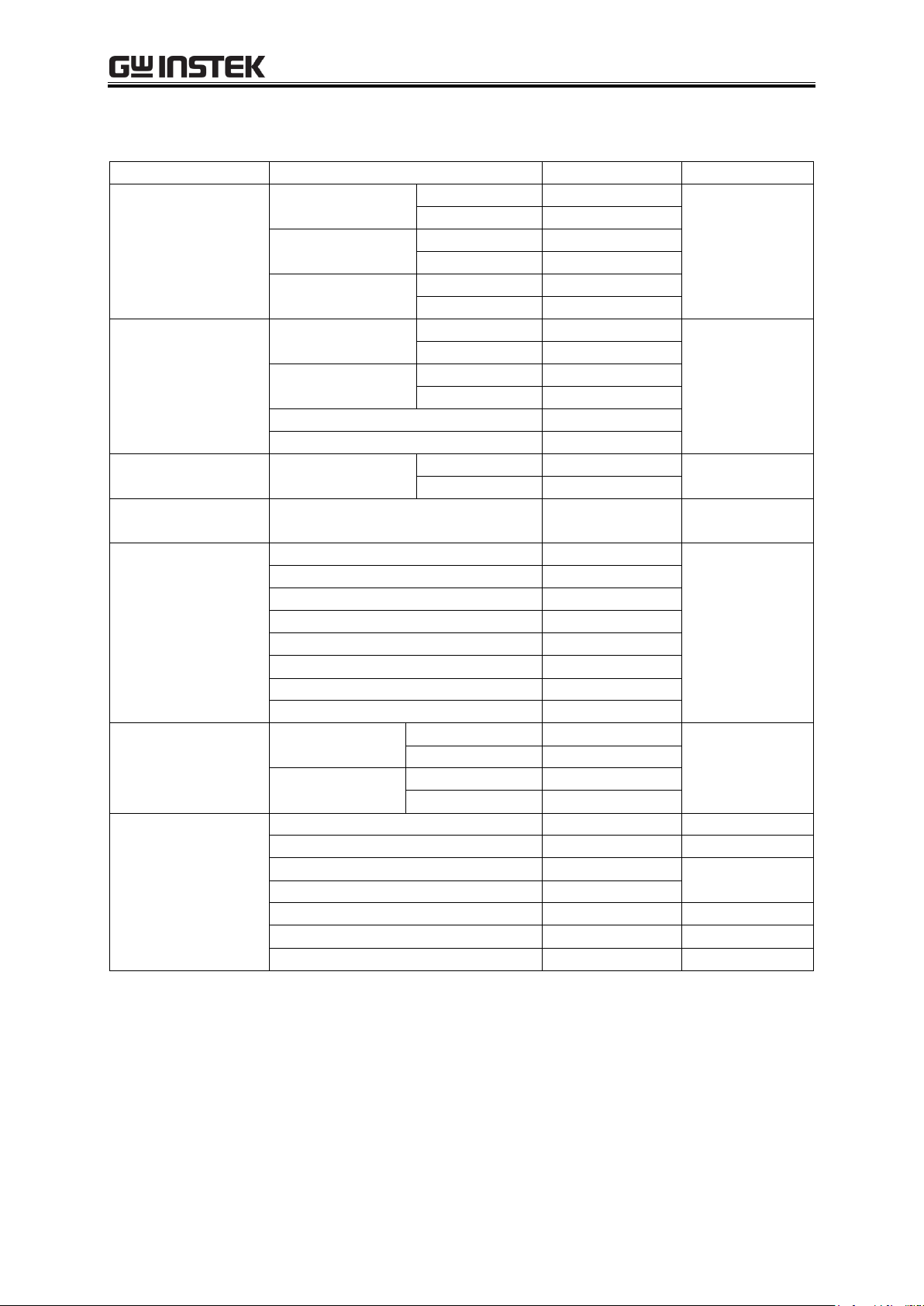
Function
Description
Output
system
Output mode
Total of 8 modes
(combinations of operation mode and signal source mode)
Alternate current - internal signal source
(AC-INT mode)
Alternate current - external signal source
(AC-EXT mode)
Alternate current - internal + external signal sources
(AC-ADD mode)
Alternate current - external synchronization
(AC-SYNC mode)
Direct current - internal signal source
(AC+DC-INT mode)
Direct current - external signal source
(AC+DC-EXT mode)
Direct current - internal + external signal sources
(AC+DC-INT mode)
Direct current - external synchronization
(AC+DC-SYNC mode)
Output on/off switch
Output voltage range
100 V range and 200 V range
Output voltage waveform
(not including external signal
source mode)
Sine wave, square wave, arbitrary waveform (16 types)
Current limiter
Peak current limiter function and RMS current limiter
function (variable limit values)
Setting range limiter
(not including external signal
source mode)
Setting range limiter function for output voltage and
output frequency
Internal mode (AC-INT, AC+DC-INT) and internal +
external mode (AC-ADD, AC+DC-ADD) only
Setting range limiter function for output voltage
External synchronization mode (AC-SYNC,
AC+DC-SYNC)
Sequential output
Output parameters: jump or sweep.
Synchronized output
Can be synchronized with external sync signal or line
frequency
Measure
ment
function
Basic measurements
Voltage: RMS, average, peak
Current: RMS, average, peak, peak hold
Power: Effective, reactive, apparent
Others
Synchronization frequency: Only in SYNC mode
Load power factor
Load crest factor
Harmonic current: 50 Hz/60 Hz fundamental only, up to
40th
1.4 List of Functions
The main functions of the APS-1102A are listed below.
Table 1-1. List of Functions (1/2)
APS-1102A
Page 22

APS-1102A User Manual
1-6
Function
Description
External
control
External control I/O
External control operation modes: Enable, disable
Control input:
Input level: High level: +4.0 V or higher
Low level: +1.0 V or lower
Non-destructive max. input: +10 V/5 V
Input impedance: Pull-up to +5 V at 47 k
Control items: Output on/off, sequence
start/stop, hold, branch
Status output:
Output level: 0 V/+5 V (open)
Output impedance: 100
Status items: Power on/off, output on/off, limiter
operation, software busy, sequence
operation step sync output
Terminal: D-sub 25-pin multi-connector
USB interface
Standard equipped
RS232 interface
Standard equipped
Table1-2. List of Functions (2/2)
APS-1102A
Page 23
1 OVERVIEW
1-7
PFC
CIRCUIT
~LINE 100V-230V
50Hz/60Hz
1.4kVA MAX
LINE
FILTER
SUB-DCPS
CIRCUIT
<1>PFC
INVERTER
ISO
CIRCUIT
(PRI)
ISO
CIRCUIT
(SEC)
<3>AMP 1
<4>AMP
INVERTER
OUTPUT
±44 0Vpk MAX
1kVA MAX
CONTROL
I/O
USB
EXT SIG IN
±2. 2V M AX
Zin=10kΩ
EXT SYNC IN
TTL
PANEL
<2>CONTROLLER
OSC
AMP
CONTROL
SYSTEM
CONTROL
DISPLAY
POWER
AMP
OUTPUT
AC250V MAX
1kVA MAX
ISO
CIRCUIT
(SEC)
ISO
CIRCUIT
(PRI)
POWER
AMP
PROTECT
<3>AMP 2
RANGE
CHANGER
RS232
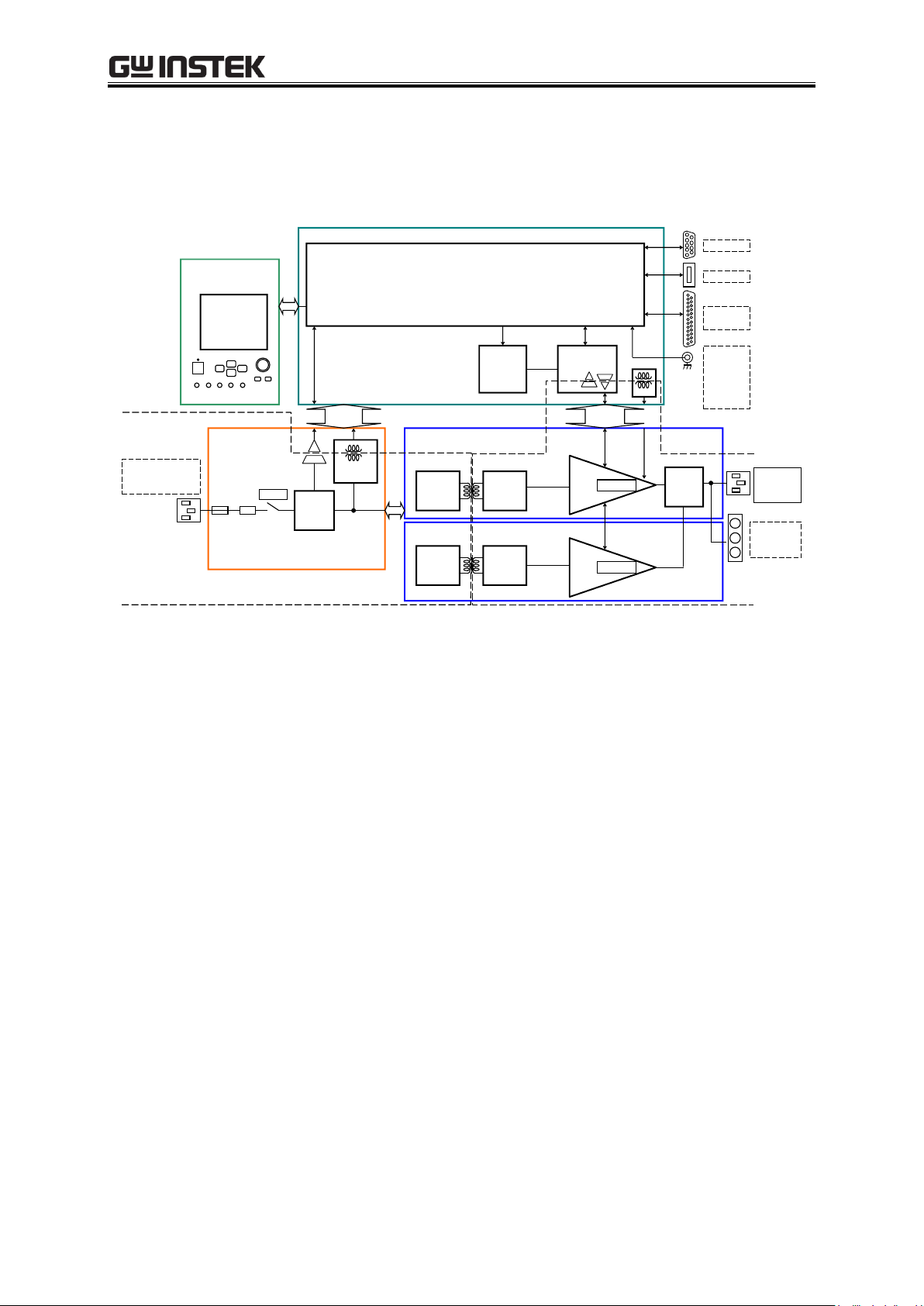
1.5 Operation Principles
Figure 1-1 shows a block diagram of the APS-1102A.
Figure 1-1. Block Diagram
The APS-1102A is broadly divided into four blocks.
<1> DC power source block
The DC power source block includes power factor improvement functions. The block provides DC
power sources for various devices on PCBs and for the amplifier block, while improving the power
factor of power supply input.
<2> Signal source and system control block
This block includes an internal signal source with sequence functions, and is able to provide
AC+DC output. It can also be used with added external inputs and internal signal sources. This
block also contains the user interface.
<3> Isolation block
The isolation block isolates the primary side (mains circuit) and secondary sides.
<4> Amplifier block
The amplifier block includes a protection circuit.
APS-1102A
Page 24

Page 25

2 PREPARATIONS BEFORE USE
2-1
2. PREPARATIONS BEFORE USE
2.1 Checking Before Use ........................................................ 2-2
2.2 Installation Environment ................................................... 2-3
2.3 Grounding and Power Supply Connection ........................ 2-6
2.4 Simple Operation Checks ................................................. 2-8
2.5 Calibration ...................................................................... 2-10
APS-1102A
Page 26
APS-1102A User Manual
2-2
This product contains high-voltage parts. Never remove the cover.
All internal inspections of this product are to be performed only by service technicians qualified by
GW Instek.
Instruction Manual (APS-1102A Instruction Manual) 1
Remote Control software (CD-ROM) 1
Power cord set 1 (varies depending on destination, 15 A/125 V for Japan, 2 m approx.) 1
Power cord set 2 (10 A/250 V, without plug, for Japan, North America, and Europe only,
1.5 m approx.) 1
!
WARNING
2.1 Checking Before Use
Before installing and using the APS-1102A, make sure that it has not been damaged during shipment, and
check that all the accessories and all parts of the main unit are included. If anything is missing, contact the
GW Instek or our agent from which the product was purchased.
Safety check
To ensure safety in using the APS-1102A, the user should read the following sections of this
instruction manual before using the APS-1102A:
See “Safety Precautions” (provided at the beginning of this instruction manual)
See “2.3 Grounding and Power Supply Connection”
Appearance and accessories check
If an abnormality (such as a flaw or dent) is found on the outside surface of the corrugated box,
carefully check if the product is adversely affected when removing the product from the corrugated
box.
After opening the corrugated box, check the items contained in the box.
If an abnormality such as a flaw or dent is found on the product, or an accessory is missing, contact
GW Instek or our agent.
Appearance check
Check that no abnormalities such as a flaw and dent are found on the panel, controls, connectors, and
so forth.
Accessories check
The accessories of this product are listed below. Check that there are no missing items and no flaws
are found.
APS-1102A
Page 27

2 PREPARATIONS BEFORE USE
2-3
If the APS-1102A is exposed to sudden shifts in ambient temperature and/or humidity during
transportation in winter, internal condensation may occur.
In such a case, leave the APS-1102A until the condensation has cleared before connecting the
APS-1102A to a power supply.
!
CAUTION
2.2 Installation Environment
Note the following precautions to ensure the safe use and reliability of this product.
Installation sites
Do not set the product on its rear, top and side when installing it on a floor or desktop.
Make sure that the four rubber feet on the bottom of the product are set evenly on a flat surface
when placed on a floor or desktop.
To prevent risk of toppling, be sure to set this product on a surface that is level and is not subject to
vibration, so that it can securely support this product weight (approximately 9.7 kg).
Cautions for transport
When transporting this product, use the grips on the left side to keep the product upright while moving
it horizontally.
When transporting this product by hand cart, mount it on a horizontal surface, so that all four rubber
feet equally support its weight.
APS-1102A
Page 28
APS-1102A User Manual
2-4
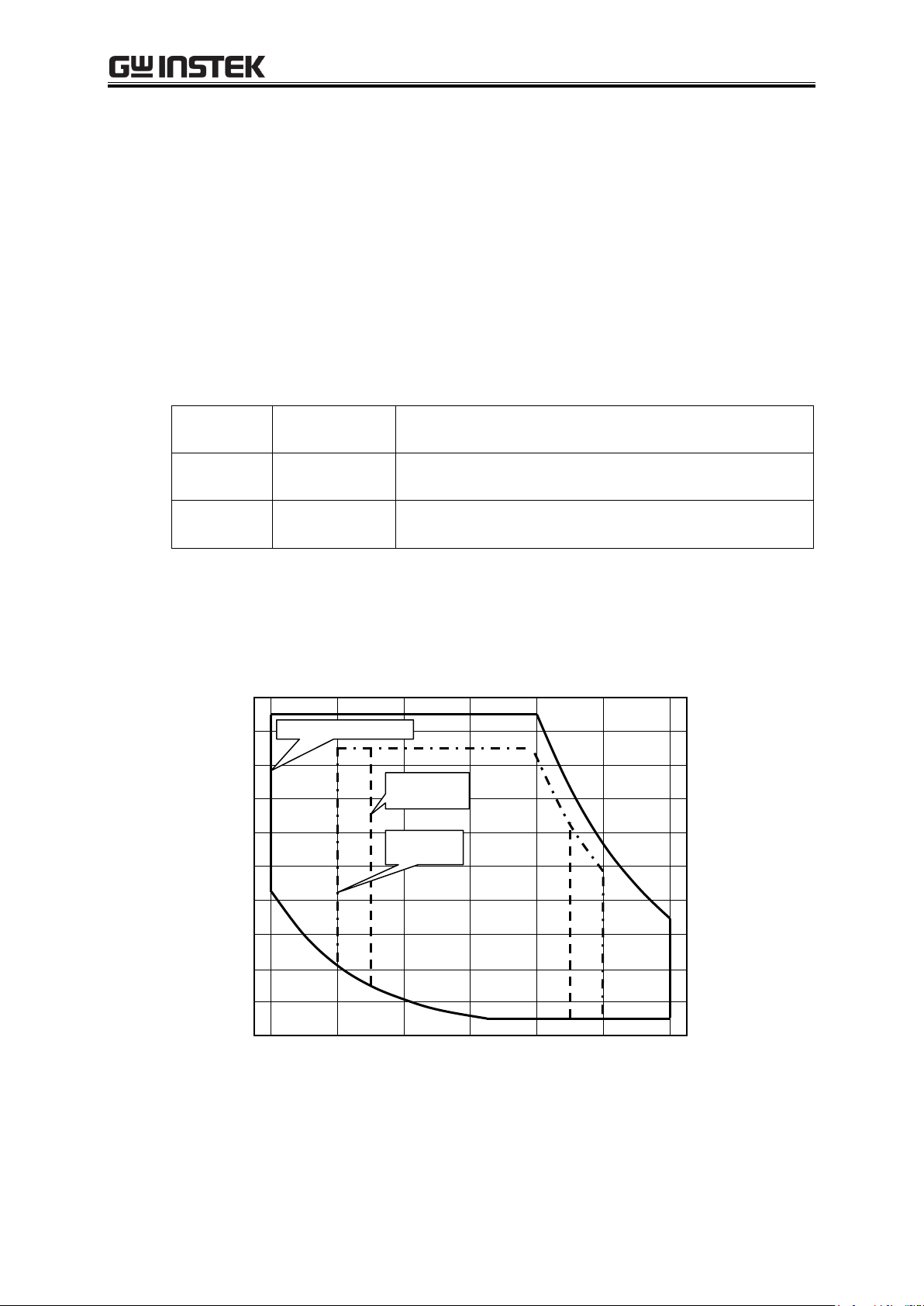
Operation
guarantee
0°C to +40°C
5% to 85%RH
Absolute humidity of 1 g/m3 to 25 g/m3, no condensation.
Performance
guarantee
+5°C to +35°C
5% to 85%RH
Absolute humidity of 1 g/m3 to 25 g/m3, no condensation.
Storage
condition
10°C to +50°C
5% to 95%RH
Absolute humidity of 1 g/m3 to 29 g/m3, no condensation.
10 0 10 20 30 40 50 C
Performance
guarantee
%RH
90
80
70
60
50
40
30
20
10
0
Storage condition
Operation
guarantee
Conditions of installation site
The APS-1102A should be used indoors, and at altitude up to 2000 m.
The APS-1102A uses a fan for forced-air cooling. To allow for ample air flow, be sure to
maintain a gap of at least 50 cm between the air inlets and outlets along the sides and rear of
this product and walls or other obstructions.
Do not stack the product on top of the other, or place it in front or back of the other
(arrangement which makes the cabinet placed behind inhale the exhaust heat of the other).
Install this product in a location that meets the following conditions for temperature and
humidity ranges.
Product reliability may decline in extreme temperature and/or humidity environments. An
environment of approximately 25°C and 50%RH is recommended.
Figure 2-1 illustrates these ambient temperature and humidity ranges.
Figure 2-1. Ambient Temperature and Humidity Ranges
APS-1102A
Page 29

2 PREPARATIONS BEFORE USE
2-5
Do not install the APS-1102A in the following locations:
Location with flammable gas
An explosion may occur. Never install and use this product in such a location.
Outdoors, or location exposed to direct sunlight or near a fire or heat source
The full performance of this product may not be obtained, or failure may occur.
Location with corrosive gas, moisture, or high humidity
This product may become corroded or fail.
Location near an electromagnetic field source, high-voltage device, or power line
This product may malfunction.
Location exposed to excessive vibration
This product may malfunction or fail.
Location with excessive dust
In particular, electrically conductive dust may cause failure of this product.
APS-1102A
Page 30

APS-1102A User Manual
2-6
This product uses a line filter. Be sure to ground this product. Otherwise, an electric shock
may occur.
To prevent an electric shock from occurring, be sure to ground the APS-1102A according to
"Electric Equipment Technical Standard Class D (100 or less) Grounding" or higher.
The power code set can be used for disconnecting the product from AC power line in case of
emergency. Maintain enough space around the inlet, to be able to remove the connector of a power
cord from the inlet. Use a power socket located at convenient place with adequate space around so
that the plug can be removed from socket.
!
WARNING
!
CAUTION
2.3 Grounding and Power Supply Connection
Be sure to ground the APS-1102A.
When the input power line is 100 V AC, use power cord set 1. When a 3-prong power plug that
includes a protective ground contact is connected to a 3-prong power supply outlet, this product is
grounded automatically. Power cord set 1 (Japan version) is rated at 125 V AC.
When the input power line is 200 V AC, use power cord set 2 equipped with a terminal or crimp
contact that suits the type of outlet to be used. Always connect a ground when using power cord set 2.
Power cord set 2 is rated at 250 V AC.
A 3-prong/2-prong conversion adapter is not provided with this product. If a 3-prong/2-prong
conversion adapter is used, the adaptor ground wire must be connected to a ground contact next to the
outlet.
The power requirements of this product are as follows:
Voltage range: 100 V AC to 230 V AC 10 % (when at 250 V or less)
Overvoltage category II
Frequency range: 50 Hz 2 Hz /60 Hz 2 Hz (single phase)
Power consumption: 1.4 kVA or less
APS-1102A
Page 31

2 PREPARATIONS BEFORE USE
2-7
Inlet
Before connecting the accompanying power cord set 2 to a touchable terminal, be sure to interrupt a
power supply. An electric shock may occur.
The accompanying power cord set 1 (Japan version) complies with Japan Electrical Appliance and
Material Safety Law and is for use in Japan only. The rated voltage is 125 V AC and the withstand
voltage is 1250 V AC. This power cord set cannot be used when the voltage exceeds 125 V AC or in
locations outside of Japan.
The accompanying power cord set 2 is intended for use in Japan, North America, and Europe. The
rated voltage is 250 V AC and the withstand voltage is 2000 V AC. Attach a plug or crimp contact
that suits the use environment. When using this cord set in Japan, be sure to use a plug that complies
with Japan Electrical Appliance and Material Safety Law.
The accompanying power cord sets are for use with this product only. Do not use them with other
products or application systems. Use only the attached power code set for connection to AC power
line.
!
CAUTION
!
CAUTION
!
CAUTION
!
WARNING
Connect the power in this order.
1. Make sure that the power source voltage to be used is within the specified range.
2. Set the power switch to off.
3. Insert the power cord into the inlet on the rear panel.
Figure 2-2. Power Source Inlet
4. Insert the power cord plug into a 3-prong power source outlet (use the supplied power source cord
set 1).
The product itself has a withstand voltage of 1500 V AC.
APS-1102A
Page 32
APS-1102A User Manual
2-8
This product contains high-voltage parts. Never remove the cover.
All internal inspections of this product are to be performed only by service technicians qualified by
GW Instek.
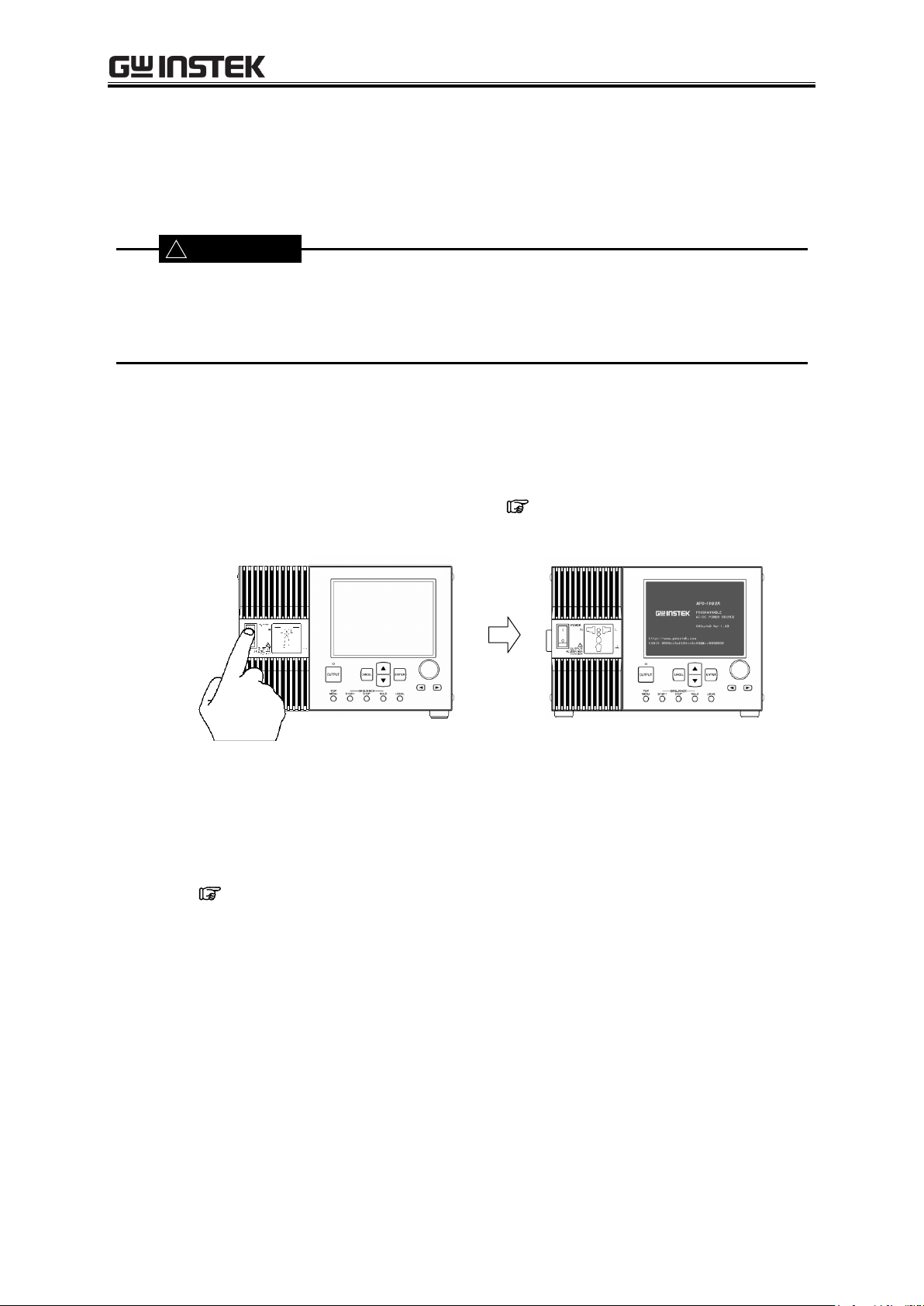
<1> Press switch to up ( | ) position.
<2> The LCD goes on and displays the initial screen.
!
WARNING
2.4 Simple Operation Checks
The following describes simple methods for checking newly purchased products or products that have
been in long-term storage.
Check that the power goes on normally, and that the measured value set via the control panel is displayed
correctly on the MEASURE screen.
Operation steps
1. Set the APS-1102A power source switch to on. See “3.4.1 Power on/off”.
Operation starts once the power is on.
The main operations screen that appears immediately after the power-on shows the same
settings that were displayed the last time the power was turned off. When a newly purchased
unit is turned on for the first time, the initial settings (factory settings) are displayed.
See “3.2 Display and Initial Settings at Power-on”, for description of the initial
settings.
APS-1102A
Page 33
2-9
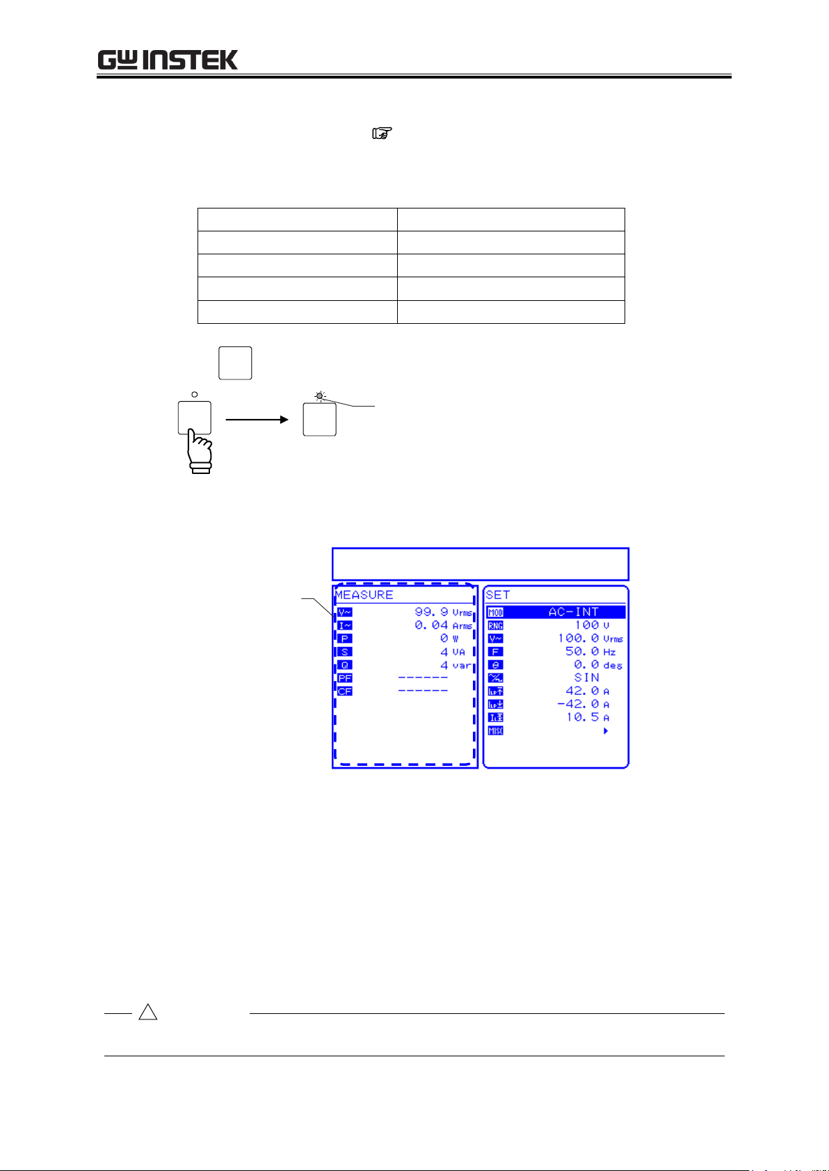
Item
Setting
Output mode
AC-INT mode
Output voltage range
100 V
AC output voltage
100 Vrms
Selected measurement display
RMS
OUTPUT
OUTPUT
OUTPUT
Output is off.
Output is on.
Before turning off the power, make sure that the output on/off LED is off.
Output on/off LED is on.
Check display.
!
CAUTION
2. Panel settings
Set the APS-1102A as shown below. See “3.4 Main Operation Example”, for descriptors
of the settings methods.
2 PREPARATIONS BEFORE USE
Table2-1. Panel Settings for Operation Check
3. Press the
key to turn on output.
⇒ Check that the control panel MEASURE screen shows 100 Vrms as the AC output voltage.
Figure 2-3. Operation Check
⇒ If the normal values are not displayed, it may be due to an operation fault. Contact GW Instek or
our agent.
4. When you turn off the power, check the OUTPUT on/off LED is off. Then press the power
switch to the bottom () position. This shuts off the power supply and turns off the power
source unit.
APS-1102A
Page 34

APS-1102A User Manual
2-10
2.5 Calibration
To calibrate the APS-1102A, contact GW Instek or our agent.
APS-1102A
Page 35

3 PANEL AND BASIC OPERATIONS
3-1
3. PANEL AND BASIC OPERATIONS
3.1 Panel Components and Operations .................................. 3-2
3.1.1 Operation panel ......................................................... 3-2
3.1.2 Front panel ................................................................ 3-3
3.1.3 Rear panel ................................................................ 3-4
3.2 Display and Initial Settings at Power-on ........................... 3-5
3.3 I/O Terminals .................................................................... 3-8
3.3.1 Output terminals (front and rear) ............................... 3-8
3.3.2 RS232 connector ...................................................... 3-11
3.3.3 USB connector ........................................................ 3-12
3.3.4 External control I/O ................................................. 3-13
3.3.5 External signal input/external sync signal input terminal .
................................................................................ 3-15
3.4 Main Operation Example ............................................... 3-16
3.4.1 Power on/off ............................................................ 3-17
3.4.2 Setting output mode ................................................ 3-19
3.4.3 Setting output voltage range .................................... 3-21
3.4.4 Setting waveform ..................................................... 3-23
3.4.5 Setting output voltage .............................................. 3-24
3.4.6 Setting output frequency.......................................... 3-26
3.4.7 Using limiter functions ............................................. 3-28
3.4.8 Output on/off ........................................................... 3-32
3.4.9 Using measurement functions ................................. 3-33
3.5 Output Characteristics .................................................... 3-36
APS-1102A
Page 36
APS-1102A User Manual
3-2
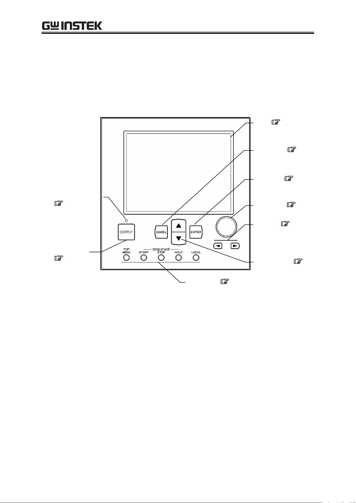
Shortcut keys
5.2.6
DIGIT key
5.2
UP/DOWN keys
5.2
LCD
5.1
MODIFY dial
5.2
Output ON/OFF LED
3.4.8
ENTER key
5.2
OUTPUT key
3.4.8
CANCEL key
5.2
3.1 Panel Components and Operations
3.1.1 Operation panel
Numbers shown after names in the following figures correspond to item numbers in the detailed
descriptions below.
Figure 3-1. APS-1102A Operation Panel
APS-1102A
Page 37
3 PANEL AND BASIC OPERATIONS
3-3
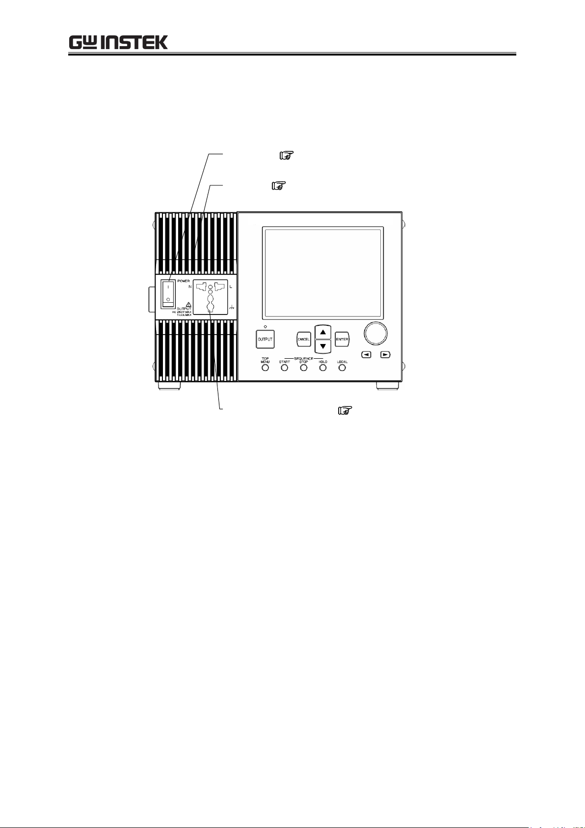
Power switch
3.4.1
Output outlets (universal type)
3.3.1
Intake vent
8.2
3.1.2 Front panel
Numbers shown after names in the following figures correspond to item numbers in the detailed
descriptions below.
Figure 3-2. APS-1102A Front Panel
APS-1102A
Page 38
APS-1102A User Manual
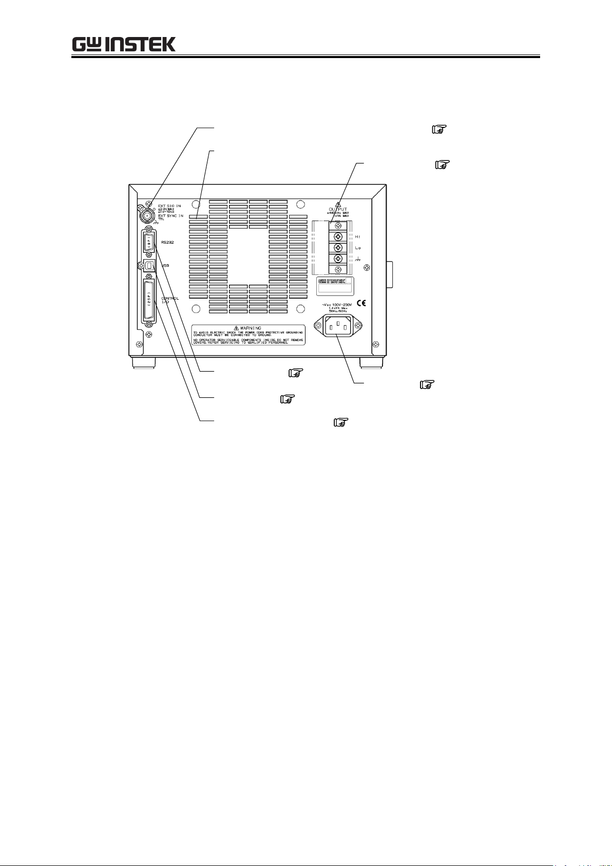
3-4
External signal input/external sync signal input connector
3.3.5
External control I/O connector
3.3.4
Output terminals
3.3.1
LINE INPUT
2.3
USB connector
3.3.3
Exhaust vent
RS232 connector
3.3.2
3.1.3 Rear panel
Figure 3-3. APS-1102A Rear Panel
APS-1102A
Page 39

3 PANEL AND BASIC OPERATIONS
3-5
Function
Setting
Initial Setting
Reset
Select output mode
Output mode
AC-INT
Select output voltage
range
Output voltage range
100 V
Select external sync
signal source
External sync signal source
LINE
AC mode output
(AC-INT,
AC-ADD,
AC-SYNC)
AC voltage
100 V range
SIN/SQU
0.0 Vrms
ARB1 to ARB16
0.0 Vp-p
200 V range
SIN/SQU
0.0 Vrms
ARB1 to ARB16
0.0 Vp-p
AC voltage frequency
50.0 Hz
Phase when the output turns on
0.0
AC voltage waveform
Sine wave (SIN)
AC+DC mode output
(AC+DC-INT,
AC+DC-ADD,
AC+DC-SYNC)
DC voltage
100 V range
0.0 V
200 V range
0.0 V
AC voltage
100 V range
SIN/SQU
0.0 Vrms
ARB1 to ARB16
0.0 Vp-p
200 V range
SIN/SQU
0.0 Vrms
ARB1 to ARB16
0.0 Vp-p
AC voltage frequency
50.0 Hz
Phase when the output turns on
0.0
AC voltage waveform
Sine wave (SIN)
3.2 Display and Initial Settings at Power-on
Display at power-on
When the power switch is set to on, a fault check is performed automatically, and when that ends
normally operation mode is set.
The settings shown on the panel are those that were shown the last time the power source was turned
off. When a newly purchased unit is turned on for the first time, the initial settings are displayed.
See “4.8 Using Memory Functions”, for description of how to read settings saved to
memory.
An error message is displayed when an abnormality has occurred. After reading the error message,
turn the power source off immediately.
See “7.2.1 Error at power-on”, for description of error messages and recommended
responses.
Initial settings
Table3-1 to Table3-3 list the initial settings for the APS-1102A. When you reset this product, the items
with a check mark in Table3-1 to Table3-3 are set to the initial setting value. Turn the output off, before
reset.
Table3-1. Settings in Memory (1/3)
APS-1102A
Page 40
APS-1102A User Manual
3-6
Function
Setting
Initial setting
Reset
Current limiter
Peak current limiter
(positive)
100 V range
+42.0 A
200 V range
+21.0 A
Peak current limiter
(negative)
100 V range
42.0 A
200 V range
21.0 A
RMS current limiter
100 V range
10.5 A
200 V range
5.3 A
Setting range limit
Positive voltage
setting limit
100 V range
+220.0 V
200 V range
+440.0 V
Negative voltage
setting limit
100 V range
220.0 V
200 V range
440.0 V
Frequency upper limit setting limit
550.0 Hz
Frequency lower limit setting limit
1.0 Hz
External input gain
setting
External input gain
100 V range
100
200 V range
200
Select measurement
display
Measurement display
RMS
Sequence output
Step time
0.1000 s
Step operation type
Constant (CONST)
Step end phase enable/disable
Disable (DISABLE)
Step end phase
0.0
Step termination
End (STOP)
Jump steps
0
Jump count
1
Branch steps
0
Adjusting DC offset
AC mode
100 V range
0.0 mV
200 V range
0.0 mV
DC mode
100 V range
0.0 mV
200 V range
0.0 mV
System settings
Keylock
OFF
Beep
ON
LCD contrast
55
LCD display color
White(WHITE)
Time unit s
Output on/off at power-on
OFF
External control input enable/disable
Disable(DISABLE)
Table3-2. Settings in Memory (2/3)
APS-1102A
Page 41

3 PANEL AND BASIC OPERATIONS
3-7
Function
Setting
Initial setting
Reset
Remote
Interface
USB
RS232
Baud rate
9600 bps
Terminator
“CR” ”LF”
Parity
None
Stop bit
1 bit
Data bit
8 bit
Flow control
None
Table3-3. Settings in Memory (3/3)
APS-1102A
Page 42

APS-1102A User Manual
3-8
Output outlets (universal type)
3.3 I/O Terminals
3.3.1 Output terminals (front and rear)
Connection to output outlet (front)
The front panel is equipped with universal type output outlets that accommodate power plug types
from various countries. These outputs are isolated from the power inputs and case (ground connection).
These outlets are used only for AC power. Use the rear output terminal for DC or AC+DC.
Polarity follows the Japanese standard. Use the rear output terminal for polarity-related settings such
as the initial phase.
Figure 3-4. Output Outlets (Front)
APS-1102A
Page 43

3 PANEL AND BASIC OPERATIONS
3-9
Output terminal
When output is on, do not touch the output terminal block.
To ensure safety, always attach the supplied terminal cover.
!
WARNING
Connection to output terminals (rear)
Outputs are isolated from the input power lines and the case (ground connection). When connecting to
an output terminal, attach a round crimp contact with a sleeve that has sufficient capacity for the output
current.
DC output is based on “Lo”, so that the + polarity setting sets “Hi = positive”, and the - polarity
setting sets “Hi = negative”.
Figure 3-5. Output Terminals (Rear)
APS-1102A
Page 44

APS-1102A User Manual
3-10
To tighten: Turn clockwise.
To loosen: Turn counterclockwise.
To ensure safety, always turn the power off before connecting to output cables.
When using the APS-1102A as a DC power supply, it is necessary to connect a diode for protection,
depending on the load, such as a capacitor and inductor.
For how to connect a diode for protection, See “4.1.1 Connecting output terminal to
load during DC output”.
!
WARNING
!
CAUTION
Connect cables to the output terminal block as described below.
Outputs are isolated from the input power lines and case.
1. Remove a screw attached to the output terminal block.
2. Insert the screw through the round crimp contact at the end of the cable.
3. Reattach the screw into the OUTPUT terminal while holding the crimp contact in place.
4. Turn the screw until it is securely fastened. The recommended fastening torque is 1.2 (Nm).
5. Connect the Hi, Lo, and ground cables, then attach the terminal cover.
Figure 3-6. Connection to Output Terminals
APS-1102A
Page 45

3 PANEL AND BASIC OPERATIONS
3-11
RS232 connector
Item
Description or Selection
Terminal
D-sub 9-pin(male, UNC #4-40 screws)
Baud rate
9600 bps / 19200 bps
Terminator
“CF”“LF” / “CR ” / “LF”
Parity
None/Odd/Even
Stop bit
1 / 2
Data bit
7 / 8
Flow control
None/Hardware/Software
3.3.2 RS232 connector
APS-1102A is equipped with the RS232 interface to control from an external computer, See “6.
REMOTE INTERFACE”.
Figure 3-7. RS232 Connector
------- Notes --------------------------------------------------------------------------------------------------------
Binary transmission is not supported.
Use a cross cable.
To transfer arbitrary waveform data, use the USB interface.
-------------------------------------------------------------------------------------------------------------------------
The specifications of RS232 interface are shown in “Table3-4. Specification of RS232
interface”.
Table3-4. Specification of RS232 interface
APS-1102A
Page 46

APS-1102A User Manual
3-12
USB connector
Item
Description
Interface
USB1.1, USBTMC
ID
Already assigned for each device
Terminator
“LF”
3.3.3 USB connector
Use a commercial (off-the-shelf) USB cable to connect the rear USB connector to a PC.
See “6. REMOTE INTERFACE”, for description of using USB connection for remote control
from a PC.
Figure 3-8. USB Connector
------- Notes --------------------------------------------------------------------------------------------------------
The USB cable should be a commercial Type A (male) to Type B (male) cable.
The use of USB hub may cause a communication failure. It is recommended to use
fully-shield, short cable.
-------------------------------------------------------------------------------------------------------------------------
The specifications of USB interface are shown in “Table3-5. Specification of USB interface”.
Table3-5. Specification of USB interface
APS-1102A
Page 47

3 PANEL AND BASIC OPERATIONS
3-13
External control I/O
connector
3.3.4 External control I/O
The APS-1102A is equipped with an (8-bit) external control I/O connector to enable external control
using digital signal input and status output using digital signals. The connector is a D-sub 25-pin type.
Figure 3-9. External Control I/O Connector
The signals corresponding to the pins in this connector are listed below in “Table3-6 External Control
I/O Connectors”
APS-1102A
Page 48

APS-1102A User Manual
3-14
Pin No.
I/O
Function
Remark
1
Output
Power source on/off status
0: Off
1: On
2
Output
Output on/off status
0: Off
1: On
3
Output
Limiter operation
Note
0: Off
1: On
4
Output
Software busy
0: Normal
1: Busy
5
Output
Sequence sync output 0
6 Output
Sequence sync output 1
7 Output
Undefined
8
Output
Undefined
9 GND
-
10
Input
Undefined
11
Input
Output off
Falling detection
12
Input
Output on
Falling detection
13
Input
Sequence start
Falling detection
14
Input
Sequence stop
Falling detection
15
Input
Sequence hold
Falling detection
16
Input
Sequence branch trigger 0
Falling detection
17
Input
Sequence branch trigger 1
Falling detection
18
GND
-
19
Output
+5 V
50 mA or less
20
Output
Reserved
21
Output
Reserved
22
Output
Reserved
23
Output
Reserved
24
Output
Reserved
25
Output
Reserved
Table3-6. External Control I/O Connectors
External control input and output can be used when external control has been set as enabled.
See “5.6.7 External control input enable/disable setting”.
APS-1102A
Note When peak current limiter (positive), peak current limiter (negative), RMS current limiter,
or output power limiter is operated, it is recognized as a limiter operation on.
Page 49
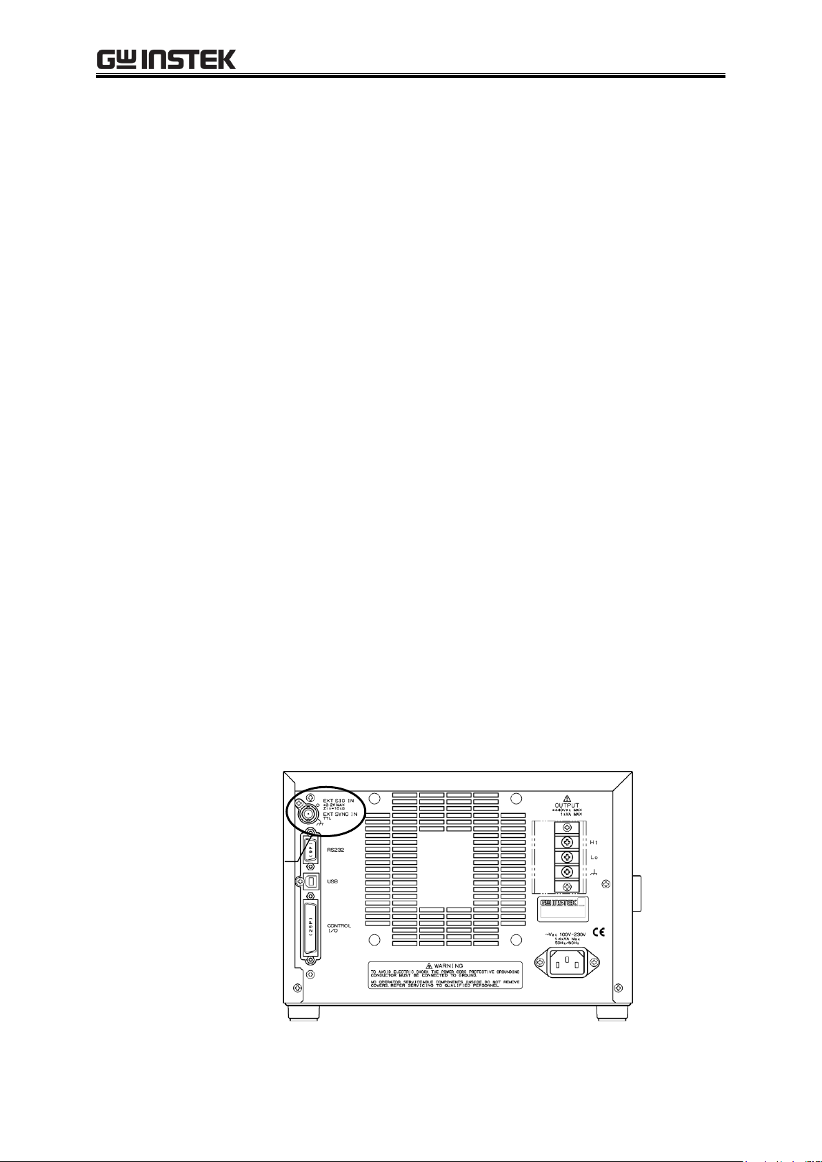
3 PANEL AND BASIC OPERATIONS
3-15
External signal input/
external sync signal input
terminal
3.3.5 External signal input/external sync signal input terminal
When using an externally input signal as the signal source with external synchronization, connect to the
external signal input/external sync signal input terminals (EXT SIG IN/EXT SYNC IN) on the rear panel.
For this connection, use a coaxial cable with a BNC connector.
The specifications for these external signal input/external sync signal input terminals are listed below.
Common specifications
Input terminal: BNC connector (used for external signal input and external
sync signal input)
Input impedance: 10 kΩ
Non-destructive maximum input voltage: 10 V
External signal input
Frequency range: DC to 550 Hz (sine wave)
DC to 100 Hz (other than sine wave)
Gain setting range: 100 V range: 0.0 times to 220.0 times (initial value is 100.0)
200 V range: 0.0 times to 440.0 times (initial value is 200.0)
Gain setting resolution: 0.1 times
Gain accuracy: 5% (DC or 45 Hz to 65 Hz, gain is at initial value, with
rated voltage output, no load)
Phase between input and output: In-phase
Input voltage range: 2.2 V to +2.2 V
External synchronization
Synchronization frequency range: 40 Hz to 500 Hz
External sync signal is not required when line
synchronization is selected.
Input voltage threshold value: TTL
Minimum pulse width 3 ms
Figure 3-10. EXT SIG IN/EXT SYNC IN Terminal
APS-1102A
Page 50

APS-1102A User Manual
3-16
3.4 Main Operation Example
Main operations are described below in the following order.
Power-on 3.4.1 Power on/off
Set output mode 3.4.2 Setting output mode
Set output voltage range 3.4.3 Setting output voltage range
Set waveform 3.4.4 Setting waveform
Set output voltage 3.4.5 Setting output voltage
Set output frequency 3.4.6 Setting output frequency
Use current limiter and setting range limiter 3.4.7 Using limiter functions
Output on 3.4.8 Output on/off
Check measured value 3.4.9 Using measurement functions
Output off 3.4.8 Output on/off
Power-off 3.4.1 Power on/off
APS-1102A
Page 51
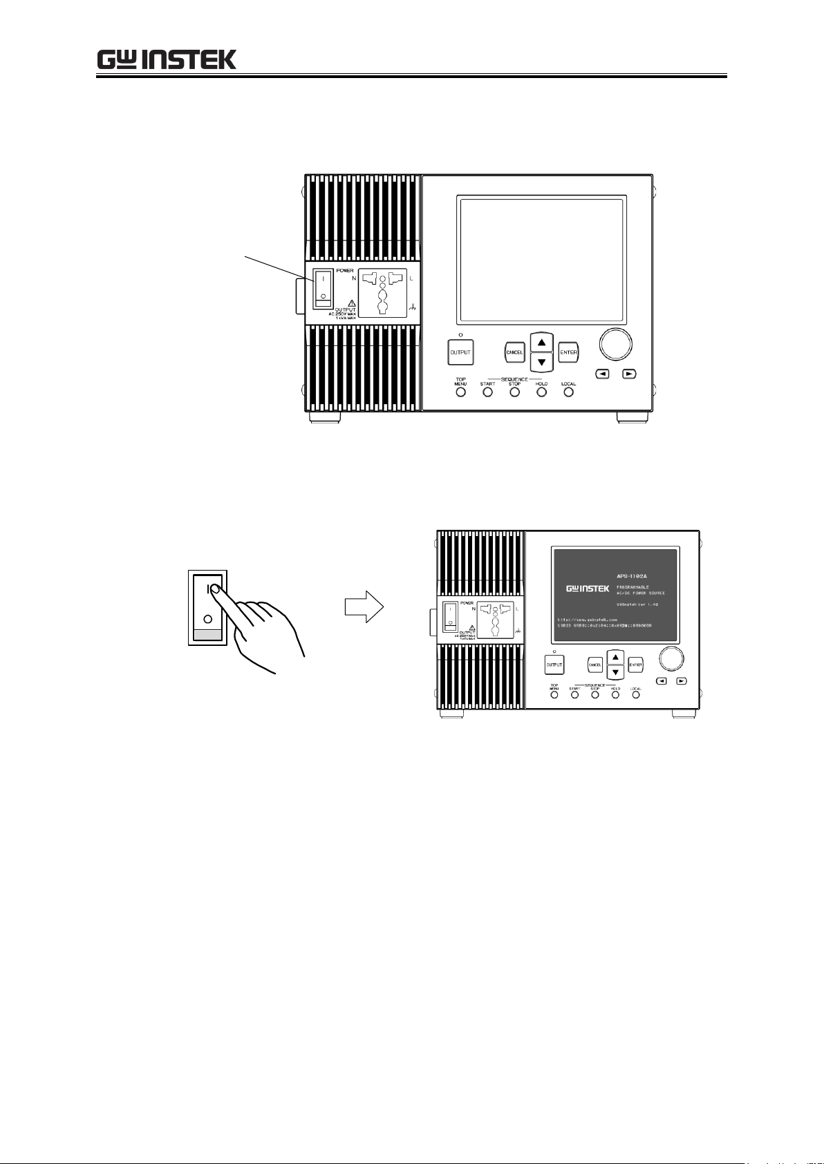
3 PANEL AND BASIC OPERATIONS
3-17
POWER switch
Startup screen is displayed.
3.4.1 Power on/off
When the POWER switch is set to “|”, the power goes on, and when it is set to “”, the power goes off.
Figure 3-11. POWER Switch
a) Power-on
Set the POWER switch to “|”.
APS-1102A
Page 52

APS-1102A User Manual
3-18
OUTPUT
OUTPUT
Output on
Output off
Before turning off the power, make sure the OUTPUT setting is off.
Before turning off the power of APS-1102A, always finish remote control. If turn off the power
during remote control, it may be caused unconformity to internal memory state.
Output mode 3.4.2
Output voltage range 3.4.3
Output voltage 3.4.5
Output frequency 3.4.6
Waveform 3.4.4
Limiter function 3.4.7
Select measurement display 3.4.9
!
CAUTION
!
CAUTION
Main operations screen is displayed.
Figure 3-12. Example of Main Operations Screen (in AC-INT Mode)
The main operations screen that appears immediately after the power-on shows the same
settings that were displayed the last time the power was turned off. When a newly purchased
product is turned on for the first time, the initial settings (factory settings) are displayed.
See “3.2 Display and Initial Settings at Power-on”, for description of the initial
settings.
See “4.8 Using Memory Functions”, for description of how to read settings saved to
memory.
See “7. TROUBLESHOOTING”, for a list of warnings and error messages, along with
recommended responses.
b) Power-off
After confirming that the output is off, set the POWER switch to “”.
⇒ The power source is cut and turned off.
APS-1102A
Page 53

3 PANEL AND BASIC OPERATIONS
3-19
Operation
Mode
Signal Source Mode
Output Mode
Reference
AC
INT
(internal)
AC-INT
“3.4.2 Setting output mode”
EXT
(external)
AC-EXT
“4.9 Amplification of External Signal”
ADD
(internal + external)
AC-ADD
“4.10 Adding External Signals and
Internal Signals ”
SYNC
(external sync)
AC-SYNC
“4.7 Synchronize the Output with
External Signal”
AC+DC
INT
(internal)
AC+DC-INT
“4.1 Use as a DC Power Source”
EXT
(external)
AC+DC-EXT
“4.9 Amplification of External Signal”
ADD
(internal + external)
AC+DC-ADD
“4.10 Adding External Signals and
Internal Signals ”
SYNC
(external sync)
AC+DC-SYNC
“4.7 Synchronize the Output with
External Signal”
3.4.2 Setting output mode
The APS-1102A provides the eight output modes listed in Table3-7. The output mode cannot be
changed while output is on. Before changing the output mode, set output to off.
Table3-7. Output Mode List
Setting to AC-INT mode is described below as an example.
APS-1102A
Page 54
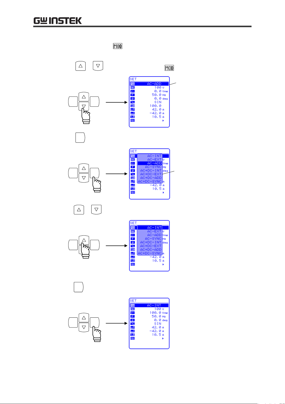
APS-1102A User Manual
3-20
ENTERCANCE L
Cursor
ENTER
ENTERCANCE L
Selection box
ENTERCANCEL
ENTER
ENTERCANCE L
Operation steps
Select output mode by selecting in the SET menu.
1. Press the or key to move the cursor to the icon.
2. Press the
key to display the selection box.
3. Press the or key to move the cursor to the mode to be set.
APS-1102A
4. Press the
key to set the selected mode.
Page 55

3 PANEL AND BASIC OPERATIONS
3-21
Setting
Setting Range
100 V range
200 V range
Unit
DC voltage
220.0 to +220.0
440.0 to +440.0
V
AC voltage
Waveform
SIN/SQU
0.0 to 155.0
0.0 to 310.0
Vrms
ARB1 to 16
0.0 to 440.0
0.0 to 880.0
Vp-p
Peak current limiter (positive)
+10.0 to +42.0
+5.0 to +21.0
A
Peak current limiter (negative)
42.0 to 10.0
21.0 to 5.0
A
RMS current limiter
1.0 to 10.5
1.0 to 5.3
A
Positive voltage setting limit
+0.1 to +220.0
+0.1 to +440.0
V
Negative voltage setting limit
220.0 to 0.1
440.0 to 0.1
V
External input gain
0.0 to 220.0
0.0 to 440.0
times
ENTERCANCE L
Cursor
3.4.3 Setting output voltage range
Select 100 V range or 200 V range. The output voltage range cannot be changed while output is on.
The setting range varies according to the output voltage range.
Table3-8. List of Setting Ranges for Various Output Voltage Range
Operation steps
To set the output voltage range, select in the SET menu.
1. Press the or key to move the cursor to the icon.
APS-1102A
Page 56
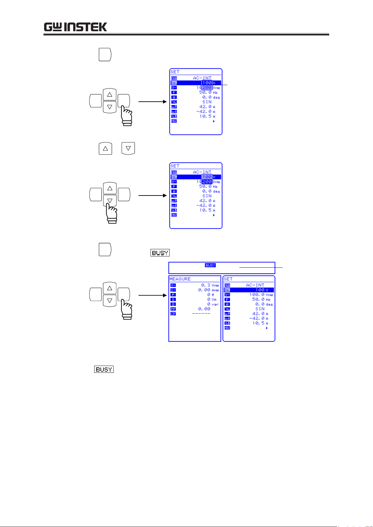
APS-1102A User Manual
3-22
ENTER
ENTERCANCE L
Selection box
ENTERCANCEL
ENTER
ENTERCANCE L
Status window
2. Press the
key to display the selection box.
3. Press the or key to move the cursor to the output voltage range to be selected.
4. Press the
⇒ The icon goes out, then the display will change to the selected output voltage range.
key. Then the
icon appears in the status window.
APS-1102A
Page 57
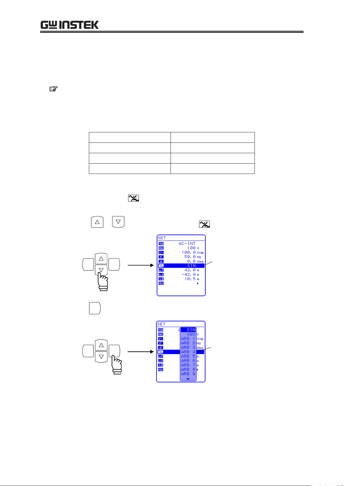
3 PANEL AND BASIC OPERATIONS
3-23
As Shown in Operation Panel
Type
SIN
Sine wave
SQU
Square wave
ARB1 to ARB16
Arbitrary waveform (16 types)
ENTERCANCE L
Cursor
ENTER
ENTERCANCEL
Selection box
3.4.4 Setting waveform
The APS-1102A allows to select a sine wave, square wave, or arbitrary waveform (16 types in all) as the
waveform to be output, by using the control panel. Arbitrary waveforms are generated using data
transfers via the USB interface.
See “4.6 Output of Arbitrary Waveforms”, for details of arbitrary waveforms.
Table3-9 lists the waveforms that can be selected.
Table3-9. Waveform List
Operation steps
To select a waveform, select in the SET menu.
1. Press the or key to move the cursor to the icon.
2. Press the
key to display the selection box.
APS-1102A
Page 58

APS-1102A User Manual
3-24
ENTERCANCE L
ENTER
ENTERCANCE L
Output Mode
Setting
Setting Range
Resolution
AC-INT
(AC mode)
AC
voltage
100 V range
SIN/SQU
0.0 to 155.0 Vrms
0.1 Vrms
ARB1 to ARB 16
0.0 to 440.0 Vp-p
0.1 Vp-p
200 V range
SIN/SQU
0.0 to 310.0 Vrms
0.1 Vrms
ARB1 to ARB 16
0.0 to 880.0 Vp-p
0.1 Vp-p
3. Press the or key to move the cursor to the waveform to be output.
4. Press the
key to set the selected waveform.
3.4.5 Setting output voltage
For AC-INT mode, the output voltage settings listed below can be selected.
Table3-10. Output Voltage Settings
See “3.4.7 Using limiter functions”, when using a setting range limit for output voltage.
See “5.3.3 Setting output voltage”, for output voltage setting ranges for other output modes.
APS-1102A
Page 59

3 PANEL AND BASIC OPERATIONS
3-25
ENTERCANCEL
Cursor
ENTER
ENTERCANCE L
Modification box
Increase
Decrease
CANCE L
ENTER
Operation steps
To set the output voltage, set in the SET menu.
1. Press the or key to move the cursor to the icon.
2. Press the
key to display the modification box.
3. Press the and keys to move the cursor to the digit to be changed, turn the MODIFY dial
and set a numerical value. The set value will be reflected in output immediately.
4. Press the
or
key to close the modification box.
APS-1102A
Page 60

APS-1102A User Manual
3-26
Setting Range
Resolution
Setting Accuracy
1.0 Hz to 550.0 Hz
0.1 Hz
0.01% (1.0 Hz to 550.0 Hz, 23 5°C)
ENTERCANCE L
Cursor
ENTER
ENTERCANCEL
Modification box
3.4.6 Setting output frequency
The AC output frequency can be set in the following range.
Table3-11. Output Frequency Setting
See “3.4.7 Using limiter functions”, when using an output frequency setting range limit.
------- Notes --------------------------------------------------------------------------------------------------------
If the frequency is set 40 Hz or lower in AC-INT mode, there is a possibility that the output
waveform will be distorted and DC offset will be output.
----------------------------------------------------------------------------------
Operation steps
To set the output frequency, set in the SET menu.
1. Press the or key to move the cursor to the icon.
2. Press the
key to display the modification box.
APS-1102A
Page 61

3 PANEL AND BASIC OPERATIONS
3-27
Increase
Decrease
CANCE L
ENTER
3. Press the and keys to move the cursor to the digit to be changed, turn the MODIFY dial
and set a numerical value. The set value will be reflected in output immediately.
4. Press the
or
key to close the modification box.
APS-1102A
Page 62

APS-1102A User Manual
3-28
Setting
Setting Range
Resolution
Initial Value
Peak current
limiter (positive)
100 V range
+10.0 A to +42.0 A
0.1 A
+42.0 A
200 V range
+5.0 A to +21.0 A
0.1 A
+21.0 A
Peak current
limiter (negative)
100 V range
42.0 A to 10.0 A
0.1 A
42.0 A
200 V range
21.0 A to 5.0 A
0.1 A
21.0 A
RMS current
limiter
100 V range
1.0 A to 10.5 A
0.1 A
10.5 A
200 V range
1.0 A to 5.3 A
0.1 A
5.3 A
Note with caution that the peak current limiter may allow overshooting, depending on the load, and
therefore may not achieve the peak current value as set.
For an inductive load, operation of the limiter can cause an output overvoltage, triggering the
overvoltage protection function. In this case, the peak current limiter settings (positive and
negative) should be reduced.
If the output current or frequency suddenly increases, due to an output short, etc., the limiter
response may not be quick enough, so the output overcurrent protection function may be triggered.
!
CAUTION
!
CAUTION
3.4.7 Using limiter functions
a) Using current limiter
The APS-1102A includes a peak current limiter function and a RMS current limiter function.
Limiter settings are retained separately for 100 V and 200 V ranges.
Setting range limits can be set for output voltage and output frequency.
See “5.3.7 Set Peak current limiter settings”.
See “5.3.8 Set RMS current limiter settings”.
Table3-12. Current Limiter Setting Ranges
For a capacitive load or inductive load, the peak current limiter may not achieve the peak current
value as set, due to overshooting or undershooting the set current value, or variable output current
waveforms while the limiter is operating.
For an inductive load, operation of the limiter can cause the current to vary and, as a result, an output
overvoltage may occur.
APS-1102A
Page 63

3 PANEL AND BASIC OPERATIONS
3-29
ENTERCANCE L
Cursor
ENTER
ENTERCANCEL
Modification box
Increase
Decrease
CANCE L
ENTER
Operation steps
Select the icon in the SET menu corresponding to the desired setting, then set a numerical value.
Peak current limiter (positive):
Peak current limiter (negative):
RMS current limiter:
1. Press the or key to move the cursor to the
,or or
icon.
2. Press the
key to display the modification box.
3. Press the and keys to move the cursor to the digit to be changed, turn the MODIFY dial
and set a numerical value. The set value will be reflected in output immediately.
4. Press the
or
key to close the modification box.
APS-1102A
Page 64

APS-1102A User Manual
3-30
Setting
Setting Range
Resolution
Initial Value
Positive voltage
setting limit
100 V range
+0.1 V to +220.0 V
0.1 V
+220.0 V
200 V range
+0.1 V to +440.0 V
0.1 V
+440.0 V
Negative voltage
setting limit
100 V range
220.0 V to 0.1 V
0.1 V
220.0 V
200 V range
440.0 V to 0.1 V
0.1 V
440.0 V
Frequency upper limit setting limit
1.0 Hz to 550.0 Hz
0.1 Hz
550.0 Hz
Frequency lower limit setting limit
1.0 Hz to 550.0 Hz
0.1 Hz
1.0 Hz
ENTERCANCEL
Cursor
ENTER
ENTERCANCE L
b) Using setting range limiter
The APS-1102A internal mode (AC-INT, AC+DC-INT) and internal + external mode (AC-ADD,
AC+DC-ADD) include setting range limiter functions for output voltage and output frequency.
See “5.5.5 Setting range limiter (LIMIT)”, for details.
Table3-13. Voltage and Frequency Setting Range Limiter
Operation steps
The setting range limit is set via the LIMIT screen under the MISC menu .
1. Press the or key to move the cursor to the icon.
2. Press the
Press the or to move the cursor key to “LIMIT”.
key to display the MISC menu.
APS-1102A
Page 65
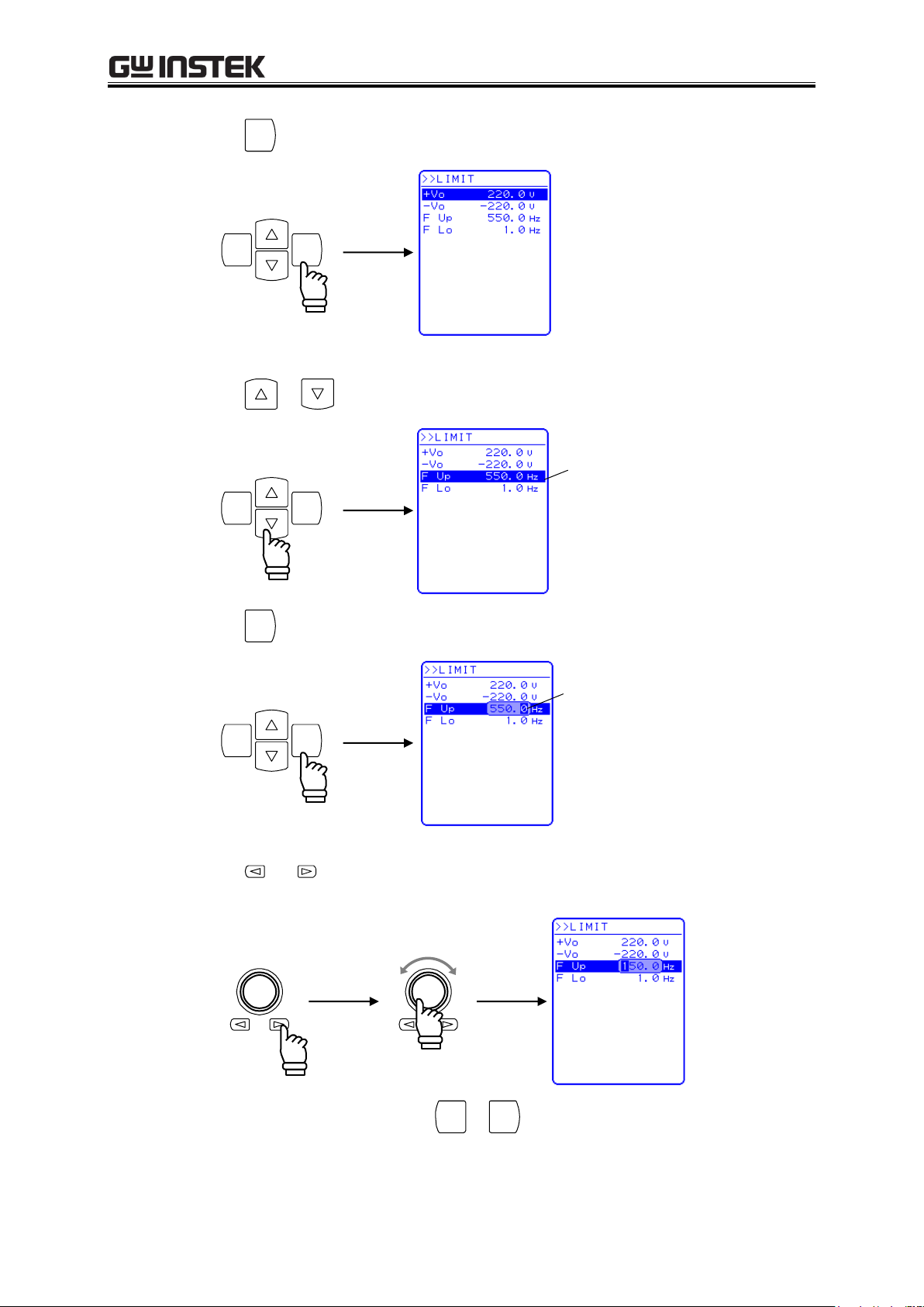
3 PANEL AND BASIC OPERATIONS
3-31
ENTER
ENTERCANCE L
ENTERCANCE L
Cursor
ENTER
ENTERCANCEL
Modification box
Increase
Decrease
CANCE L
ENTER
3. Press the
key to display the LIMIT screen.
4. Press the or key to move the cursor to the item to be set.
5. Press the
key to display the modification box.
6. Press the and keys to move the cursor to the digit to be changed, turn the MODIFY dial
and set a numerical value. The set value will be reflected in output immediately.
7. After setting all of the items, press the
or
key to close the modification box.
APS-1102A
Page 66

APS-1102A User Manual
3-32
OUTPUT
OUTPUT
OUTPUT
Output off
Output on
To ensure safety, make sure the power is off before connecting outputs.
Before turning off the power, make sure that the output on/off LED is off.
Output on/off LED on
!
WARNING
!
CAUTION
3.4.8 Output on/off
To turn the APS-1102A output on or off, simply press the
key.
When output is on, the output on/off LED goes on, and it goes off when the output is off.
The output on/off setting can be controlled via the MISC menu of the display.
See “5.5.8 Output on/off”.
APS-1102A
Page 67

3 PANEL AND BASIC OPERATIONS
3-33
3.4.9 Using measurement functions
The APS-1102A is equipped with the following measurement functions.
Voltage (RMS, average DC, peak)
Current (RMS, average DC, peak, peak hold)
Power (effective, reactive, apparent)
Synchronization frequency (external synchronization)
Load power factor
Load crest factor
Harmonic current (50 Hz/60 Hz fundamental, up to 40th harmonics)
Measured values are displayed in the measured value window MEASURE screen, which enables the
output status to be monitored.
a) Measured value window
Figure 3-13. Example of Measured Value Window (AC-INT Mode)
When a measurement is out of range, “” is displayed in the numerical value field.
b) Select measurement display
Select among RMS, AVG, PEAK, or harmonic current as the measured current and voltage values to
be displayed.
See “4.3 Measurement of Harmonic Current”, for description of harmonic current
measurements.
APS-1102A
Page 68

APS-1102A User Manual
3-34
ENTERCANCEL
Cursor
ENTER
ENTERCANCE L
ENTER
ENTERCANCEL
Selection box
Operation steps
To select a measurement display, select “MEASURE” in the MISC menu .
1. Press the or key to move the cursor to the icon.
2. Press the
Press the or key to move the cursor to “MEASURE”.
3. Press the
key to display the MISC menu.
key to display the selection box.
APS-1102A
Page 69
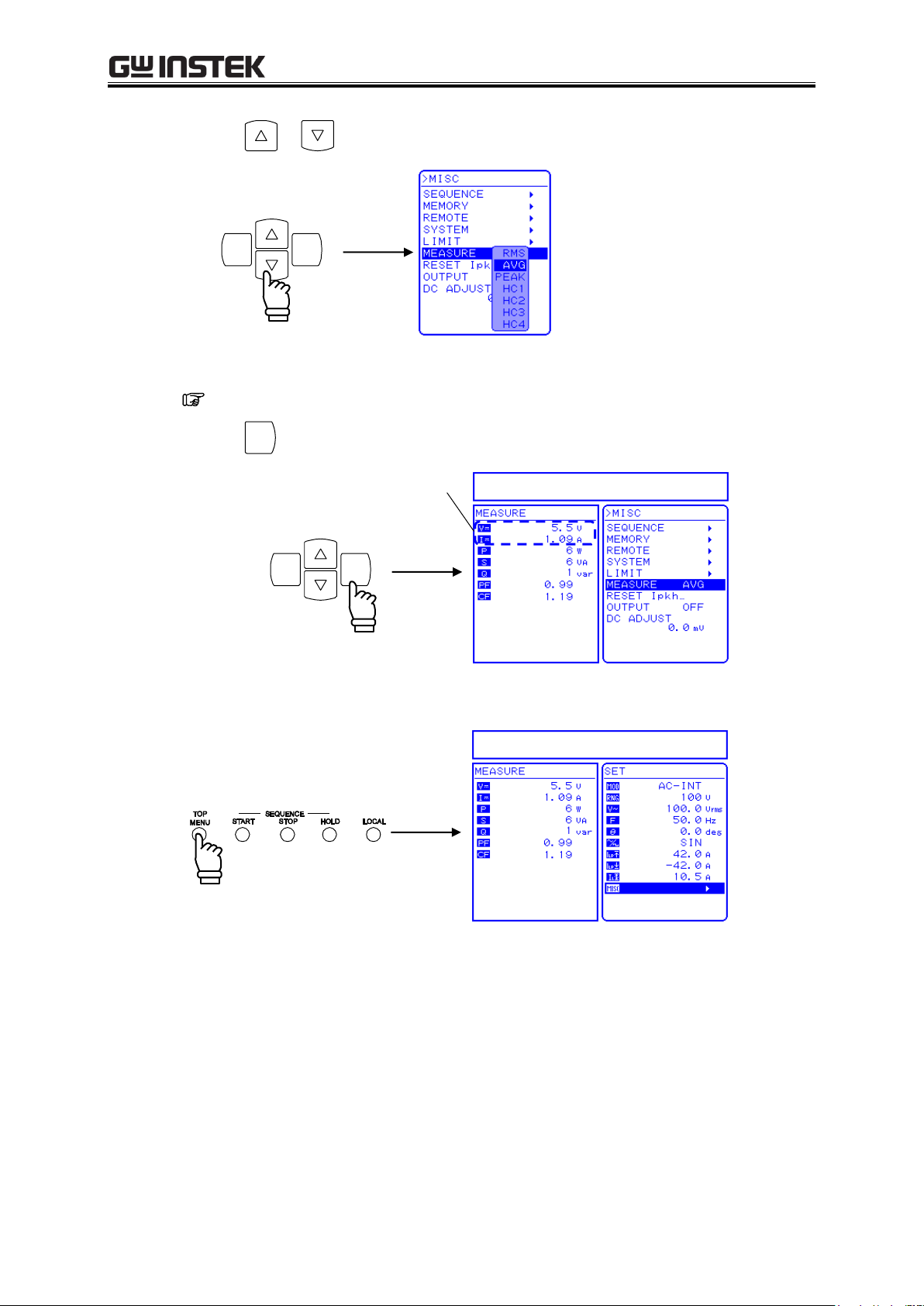
3 PANEL AND BASIC OPERATIONS
3-35
ENTERCANCE L
ENTER
ENTERCANCE L
Selected measurement display is shown.
4. Press the or key to move the cursor to the desired measurement display.
HC1 to HC4 are for measuring harmonic current.
See “4.3 Measurement of Harmonic Current”.
5. Press the
key to set the selected measurement display.
6. Press the TOP MENU key or CANCEL key to return to the SET menu screen.
APS-1102A
Page 70

APS-1102A User Manual
3-36
48.4
75.0
100.0
100.0 155.075.0
Maximum output power = 750 VA
100 V range: 100 Vrms/10 Arms
200 V range: 200 Vrms/5 Arms
-------------------------------------------------------------------------
Output voltage (Vrms)/Rated output voltage (Vrms) × 100 (%)
Output current (Arms)/Maximum output current (Arms) 100 (%)
Output range: Rated voltage/Maximum current
74.1
100.0
100.0 155.0
Maximum output power = 1000 VA
100 V range: 100 Vrms/10 Arms
200 V range: 200 Vrms/5 Arms
------------------------------------------------------------------------
Output voltage (Vrms)/Rated output voltage (Vrms) × 100 (%)
Output current (Arms)/Maximum output current (Arms) 100 (%)
Output range: Rated voltage/Maximum current
3.5 Output Characteristics
The following charts show output voltage vs. output current of the APS-1102A (resistance load, 45 Hz to
65 Hz or DC, typical character).
Figure 3-14 and Figure 3-15 show AC output characteristics, and Figure 3-16 and Figure 3-17
show DC output characteristics.
Figure 3-14. Output Voltage (AC) vs. Output Current Characteristics
(100 V AC Input, AC-INT)
Figure 3-15. Output Voltage (AC) vs. Output Current Characteristics
(200 V AC Input, AC-INT)
APS-1102A
Page 71
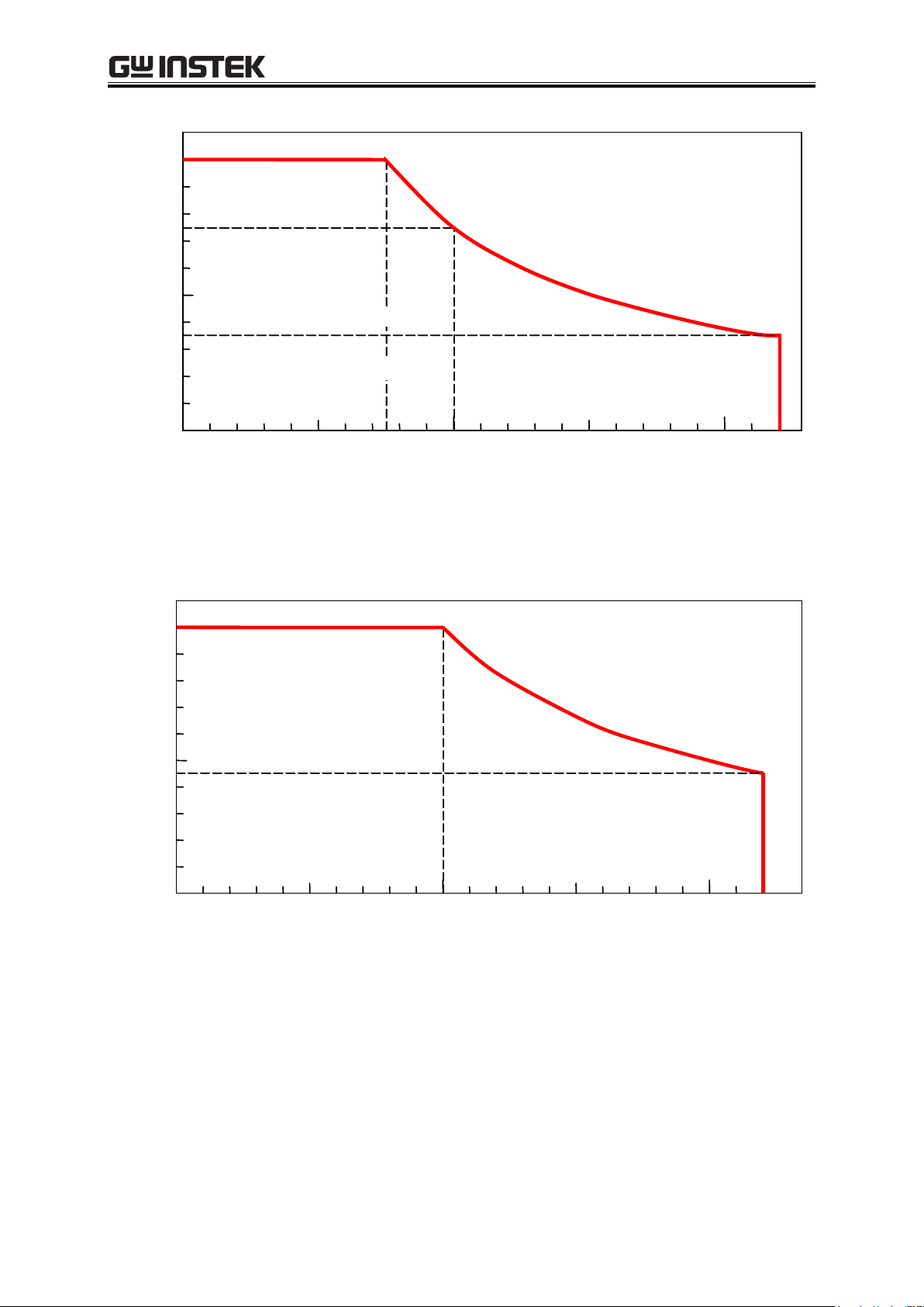
3 PANEL AND BASIC OPERATIONS
3-37
34.1
75.0
100.0
100.0 220.0200.075.0
Output current (A)/Maximum output current (A) 100 (%)
Maximum output power = 750 W
100 V range: 100 V/10 A
200 V range: 200 V/5 A
-------------------------------------------------------------------------
Output voltage (V)/Rated output voltage (V) × 100 (%)
Output range: Rated voltage/Maximum current
45.5
100.0
100.0 220.0200.0
Output voltage (V)/Rated output voltage (V) × 100 (%)
Output current (A)/Maximum output current (A) 100 (%)
Maximum output power = 1000 W
100 V range: 100 V/10 A
200 V range: 200 V/5 A
-------------------------------------------------------------------------
Output range: Rated voltage/Maximum current
Figure 3-16. Output Voltage (DC) vs. Output Current Characteristics
(100 V AC Input, AC+DC-INT, AC=0)
Figure 3-17. Output Voltage (DC) vs. Output Current Characteristics
(200 V AC Input, AC+DC-INT, AC=0)
APS-1102A
Page 72

APS-1102A User Manual
3-38
APS-1102A
Page 73

4 ADVANCED OPERATION EXAMPLE
4-1
4. ADVANCED OPERATION EXAMPLE
4.1 Use as a DC Power Source .............................................. 4-2
4.1.1 Connecting output terminal to load during DC output . 4-2
4.1.2 Selecting an output mode (AC+DC-INT mode) .......... 4-3
4.1.3 Setting the output voltage range ................................ 4-5
4.1.4 Setting the output voltage .......................................... 4-7
4.1.5 Setting output frequency of superimposed AC ........... 4-9
4.1.6 Setting superimposed AC waveform ........................ 4-10
4.1.7 Using the measurement function .............................. 4-11
4.2 Measurement of Inrush Current ...................................... 4-15
4.2.1 Inrush current .......................................................... 4-15
4.2.2 Set phase at output on ............................................ 4-16
4.2.3 Set measurement display to peak value .................. 4-17
4.2.4 Reset the peak current hold value ........................... 4-18
4.3 Measurement of Harmonic Current ................................. 4-20
4.4 Using the Sequence Function ......................................... 4-22
4.4.1 Sequence operations ............................................... 4-22
4.4.2 Sequence settings ................................................... 4-29
4.4.3 Programming sequences ......................................... 4-31
4.4.4 Control of sequence operations ............................... 4-37
4.4.5 Clear sequence memory .......................................... 4-39
4.4.6 Example of sequence operation settings ................. 4-40
4.4.7 Execution of sequence operations ........................... 4-44
4.5 Control Using External Control I/O Connector ................. 4-48
4.6 Output of Arbitrary Waveforms ........................................ 4-49
4.7 Synchronize the Output with External Signal .................. 4-51
4.7.1 External signal synchronization ............................... 4-52
4.7.2 Line synchronization ................................ ................ 4-54
4.8 Using Memory Functions ................................................ 4-55
4.9 Amplification of External Signal ...................................... 4-58
4.10 Adding External Signals and Internal Signals ................. 4-62
APS-1102A
Page 74

APS-1102A User Manual
4-2
Setting
Setting Range
Resolution
Initial Value
DC voltage
100 V range
220.0 to +220.0 V
0.1 V
0.0 V
200 V range
440.0 to +440.0 V
0.1 V
0.0 V
AC voltage
100 V range
SIN/SQU
0.0 to 155.0 Vrms
0.1 Vrms
0.0 Vrms
ARB1 to ARB16
0.0 to 440.0 Vp-p
0.1 Vp-p
0.0 Vp-p
200 V range
SIN/SQU
0.0 to 310.0 Vrms
0.1 Vrms
0.0 Vrms
ARB1 to ARB16
0.0 to 880.0 Vp-p
0.1 Vp-p
0.0 Vp-p
AC voltage frequency
1.0 to 550.0 Hz
0.1 Hz
50.0 Hz
Phase when output is on
0.0 to 359.9
0.1
0.0
4.1 Use as a DC Power Source
When using the APS-1102A as a DC voltage source, select DC - Internal signal mode (AC+DC-INT),
then enter the settings listed in Table4-1.
AC components (sine wave, square wave, and arbitrary waveform) can be superimposed on the DC power
source.
A protection diode may be required to be connected, depending on the load, such as a capacitor or
inductor.
Table4-1. Panel Settings When Using APS-1102A as a DC Power Source
The unit for AC voltage settings differs according to the AC voltage waveform setting.
4.1.1 Connecting output terminal to load during DC output
Use the output terminal on the rear panel when outputting DC+AC or only DC from the APS-1102A.
If the load is a capacitor or inductive load, connect a diode for protection that meets the following
specifications between the output terminal of the APS-1102A and the load.
Maximum reverse voltage: 600 V or higher
Maximum forward current: 15 A or more (100 V range), 7.5 A or more (200 V range)
a) Capacitive load such as capacitor (about 50 F or more) and DC-DC converter
When a capacitive load is charged, the greater the voltage changes, the more the charge
current becomes. Overshoot may be generated in the output currents depending on the load,
even if the peak current limiter of the APS-1102A operates, thus turning off the output due to
overcurrent protection.
To avoid this, gradually lower the set voltage so that decrease of the voltage changes per
certain unit time or use the sweep function of the sequence.
A block diode is required to prevent current from flowing from the load to the output terminal
of the APS-1102A even if the output voltage is lowered. Connect the diode and the load
serially as shown in Figure 4-1.
APS-1102A
Page 75

4 ADVANCED OPERATION EXAMPLE
4-3
ENTERCANCE L
Cursor
APS-1102A
Block diode
Capacitor
Lo
Hi
APS-1102A
Backflow diode
Inductor
Lo
Hi
Once a diode has been connected, a load that does not consume power keeps its voltage
charged. The voltage of the load may be slightly higher due to the overshoot voltage and
should be carefully monitored.
b) Inductive load such as inductor
An inductive load generates a back EMF when current suddenly stops flowing, such as when
the output is turned off. A backflow diode is required to absorb the back EMF.
Connect a backflow diode in parallel with the load, as shown in Figure 4-2.
Figure 4-2. Connection of Backflow Diode
Figure 4-1. Connection of Block Diode
4.1.2 Selecting an output mode (AC+DC-INT mode)
To select an output mode, select in the SET menu.
Operation steps
1. Press the or key to move the cursor to the icon.
APS-1102A
Page 76

APS-1102A User Manual
4-4
ENTER
ENTERCANCE L
Selection box
ENTERCANCE L
Cursor
ENTER
ENTERCANCE L
2. Press the
key to display the selection box.
3. Press the or key to move the cursor to “AC+DC-INT”.
4. Press the
key to set the AC+DC-INT mode.
APS-1102A
Page 77

4 ADVANCED OPERATION EXAMPLE
4-5
ENTERCANCE L
Cursor
ENTER
ENTERCANCEL
Selection box
Setting
Setting range
100 V range
200 V range
Unit
DC voltage
-220.0 to +220.0
-440.0 to +440.0
V
AC voltage
SIN/SQU
0.0 to 155.0
0.0 to 310.0
Vrms
ARB1 to ARB16
0.0 to 440.0
0.0 to 880.0
Vp-p
Peak current limiter (positive)
+10.0 to +42.0
+5.0 to +21.0
A
Peak current limiter (negative)
-42.0 to -10.0
-21.0 to -5.0
A
RMS current limiter
1.0 to 10.5
1.0 to 5.3
A
Positive voltage setting limit
+0.1 to +220.0
+0.1 to +440.0
V
Negative voltage setting limit
-220.0 to -0.1
-440.0 to -0.1
V
External input gain
0.0 to 220.0
0.0 to 440.0
times
4.1.3 Setting the output voltage range
Select 100 V or 200 V as the output voltage range.
As is shown in Table4-2, the range that can be set for the output voltage differs according to the
selected output voltage range.
Table4-2. Setting Range Options for Various Output Voltage Ranges
To select an output voltage range, select in the SET menu.
The output voltage range cannot be changed when output is on.
Operation steps
1. Press the or key to move the cursor to the icon.
2. Press the
key to display the selection box.
APS-1102A
Page 78

APS-1102A User Manual
4-6
ENTERCANCEL
ENTER
ENTERCANCE L
3. Press the or key to move the cursor to 100 V or 200 V.
4. Press the
key. Then the
icon appears in the status window.
The icon goes out, then the output voltage range changes to the selected range.
APS-1102A
Page 79

4 ADVANCED OPERATION EXAMPLE
4-7
Setting
Setting range
resolution
DC voltage
100 V range
220.0 to +220.0 V
0.1 V
200 V range
440.0 to +440.0 V
0.1 V
AC voltage
100 V range
SIN/SQU
0.0 to 155.0 Vrms
0.1 Vrms
ARB1 to ARB16
0.0 to 440.0 Vp-p
0.1 Vp-p
200 V range
SIN/SQU
0.0 to 310.0 Vrms
0.1 Vrms
ARB1 to ARB16
0.0 to 880.0 Vp-p
0.1 Vp-p
ENTERCANCE L
Cursor
ENTER
ENTERCANCE L
Modification box
4.1.4 Setting the output voltage
The ranges that can be set are listed below.
Table4-3. Output Voltage Setting Ranges When AC+DC Mode Is Selected
Output can be set so that AC voltage is superimposed on DC voltage.
The unit for AC voltage settings differs according to the AC voltage waveform setting.
When the selected AC voltage waveform is SIN/SQU, the AC voltage setting is in Vrms units, and
when it is ARB1 to ARB16, the setting is in Vp-p units.
To select an output voltage, select “DC voltage” or “AC voltage” in the SET menu, then set
a numerical value.
Operation steps
1. Press the or key to move the cursor to the or icon.
2. Press the
key to display the modification box.
APS-1102A
Page 80
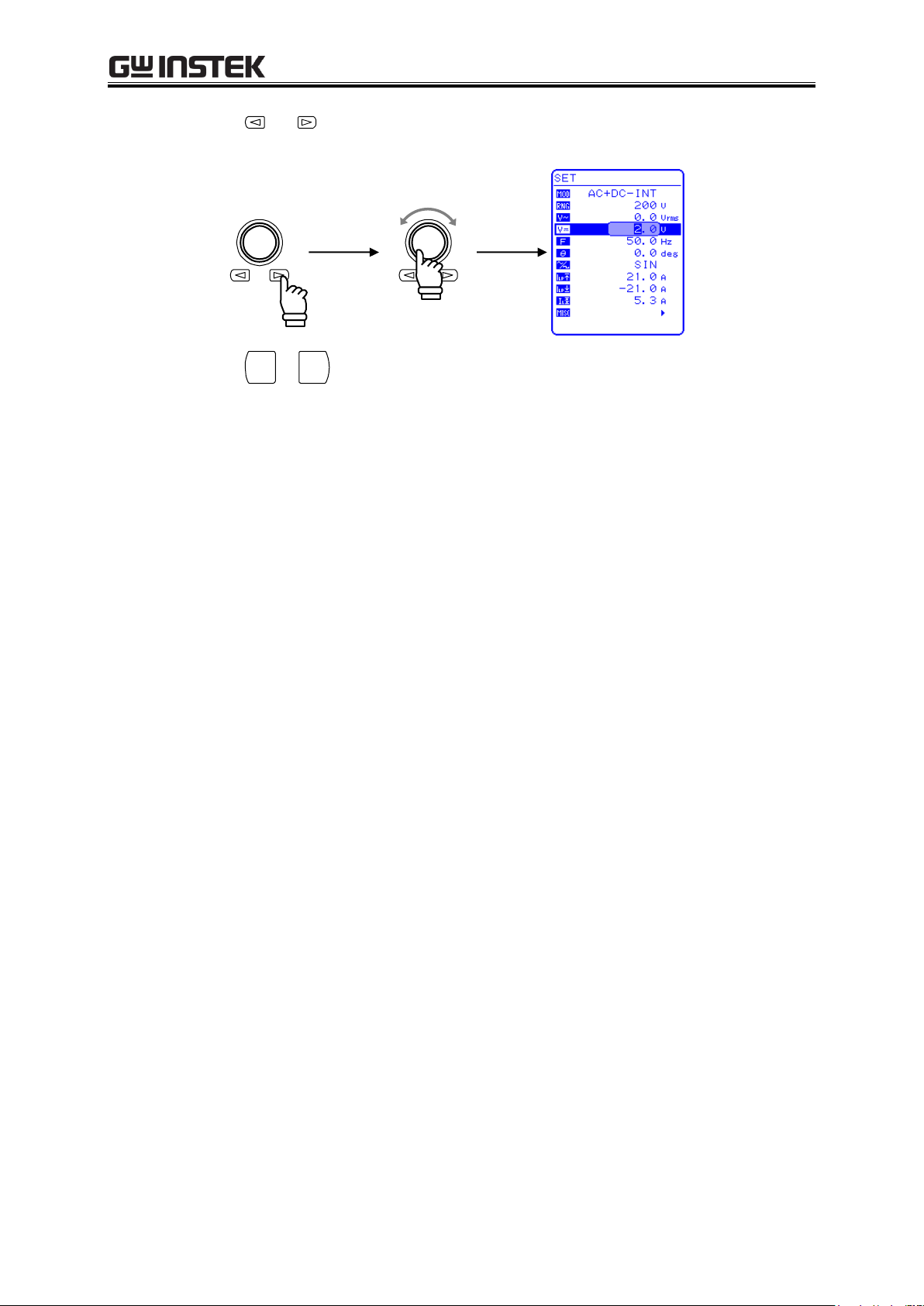
APS-1102A User Manual
4-8
Increase
Decrease
CANCE L
ENTER
3. Press the and keys to move the cursor to the digit to be changed, turn the MODIFY dial
and set a numerical value. The set value will be reflected in output immediately.
4. Press the
or
key to close the modification box.
APS-1102A
Page 81

4 ADVANCED OPERATION EXAMPLE
4-9
ENTERCANCEL
Cursor
ENTER
ENTERCANCE L
Modification box
Increase
Decrease
CANCE L
ENTER
4.1.5 Setting output frequency of superimposed AC
To set the output frequency, set a numerical value under in the SET menu.
Operation steps
1. Press the or key to move the cursor to the icon.
2. Press the
key to display the modification box.
3. Press the and keys to move the cursor to the digit to be changed, turn the MODIFY dial
and set a numerical value. The set value will be reflected in output immediately.
4. Press the
or
key to close the modification box.
APS-1102A
Page 82

APS-1102A User Manual
4-10
ENTERCANCE L
Cursor
ENTER
ENTERCANCE L
Selection box
ENTERCANCE L
4.1.6 Setting superimposed AC waveform
Selects among 16 types of sine waves (SIN), square waves (SQU), and arbitrary waveforms (ARB).
Arbitrary waveforms are generated using data transfers via the USB interface.
See “4.6 Output of Arbitrary Waveforms”, for details of arbitrary waveforms.
To select a waveform, select in the SET menu.
Operation steps
1. Press the or key to move the cursor to the icon.
2. Press the
key to display the selection box.
3. Press the or key to move the cursor to the waveform to be output.
APS-1102A
Page 83
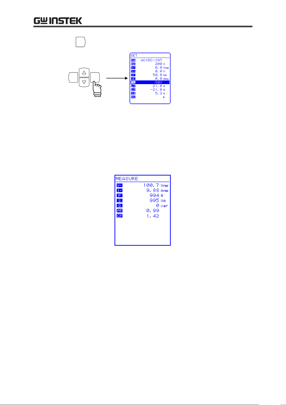
4 ADVANCED OPERATION EXAMPLE
4-11
ENTER
ENTERCANCE L
4. Press the
key to set the selected waveform.
4.1.7 Using the measurement function
Measured values are displayed in the measured value window MEASURE screen, which enables the
output status to be monitored.
a) Measured value window
Figure 4-3. Example of Measured Value Window (During AC+DC Mode)
When a measurement is out of range, “” is displayed in the numerical value field.
Select “AVG” to measure DC component only, or select “RMS” to measure the superimposed
value of DC and AC components.
The measurement values of peak voltage, peak current and harmonic current are reference values.
APS-1102A
Page 84

APS-1102A User Manual
4-12
1
0
2
1
N
n
rms
nV
N
V
1
0
2
1
N
n
rms
nI
N
I
1
0
arg
1
N
n
nV
N
V
1
0
arg
1
N
n
nI
N
I
nVMAXV
peak
nVMINV
peak
nIMAXI
peak
nIMINI
peak
1
0
1
N
n
nInV
N
W
nV
nI
N
rmsrms
IVVA
2
2
var WVA
VA
W
PF
rms
peakpeak
I
IIMAX
CF
,
peakpeakph
IIMAXholdI ,
b) Calculation method of the measurement values
Output voltage and current are sampled and A/D converted at 50 kS/s in general or at 5 kS/s when
a sequence program is running. The frequency bandwidth of each analog circuit from a voltage or
current point to the A/D converter is 50 kHz.
RMS, average and peak values of voltage or current and active power values are calculated with
following formulas and sampled values over integer multiples of their periods nearest to 100 ms.
The following values are used as the periods: frequency setting values in INT/ADD modes,
synchronization frequency measurements in SYNC modes, and fixed values to 100 ms in EXT
modes or when the frequency is lower than 10 Hz in any mode.
RMS voltage:
DC average voltage:
Max voltage:
Max current:
Active power:
However,
,
: sample output voltage/current measurement data
RMS current:
DC average current:
Min voltage:
Min current:
: Number of samples.
Apparent power, reactive power, crest factor and peak current hold are calculated from equations
below using previous calculated values.
Apparent power:
Reactive power:
APS-1102A
Power factor:
Crest factor:
Current peak hold:
Page 85
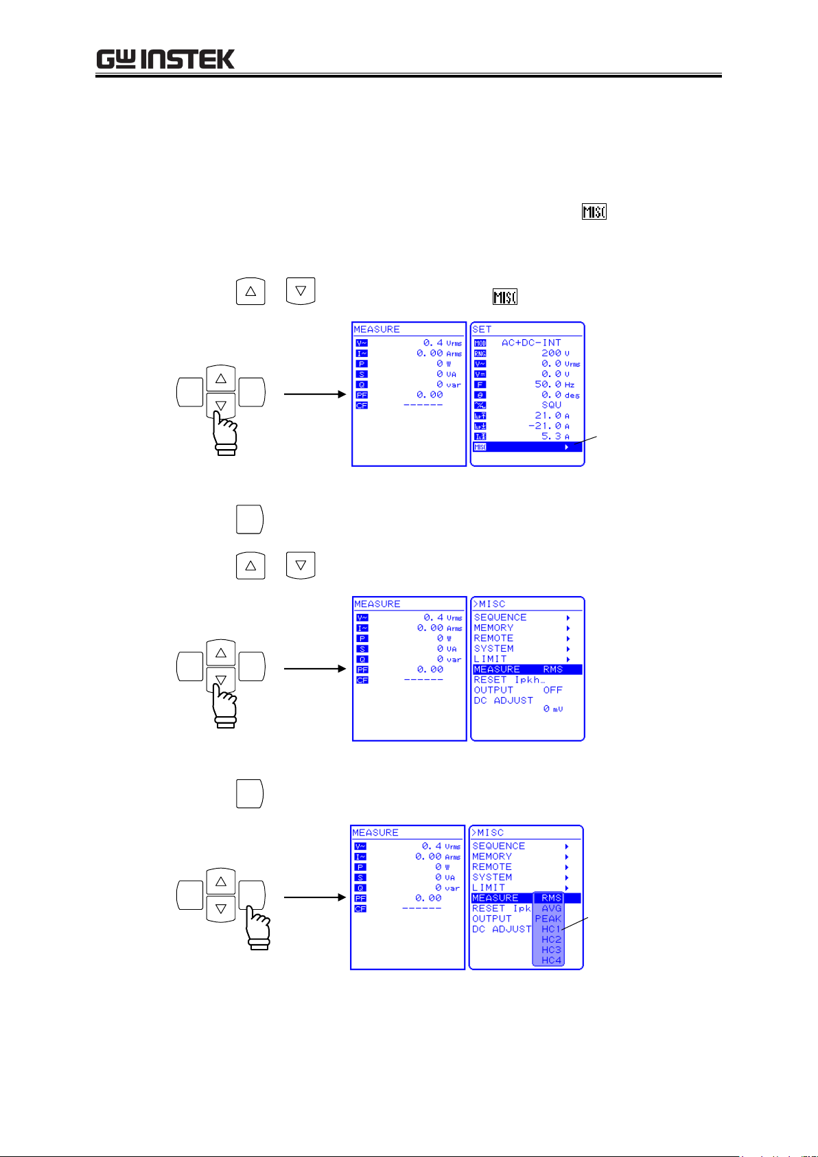
4 ADVANCED OPERATION EXAMPLE
4-13
ENTERCANCE L
Cursor
ENTER
ENTERCANCE L
ENTER
ENTERCANCE L
Selection box
c) Select measurement display
Select one form among RMS, AVG, or PEAK as the measured current and voltage values to be
displayed.
To select a measurement display, select “MEASURE” in the MISC menu .
Operation steps
1. Press the or key to move the cursor to the icon.
2. Press the
key to display the MISC menu.
Press the or key to move the cursor to “MEASURE”.
3. Press the
key to display the selection box.
APS-1102A
Page 86
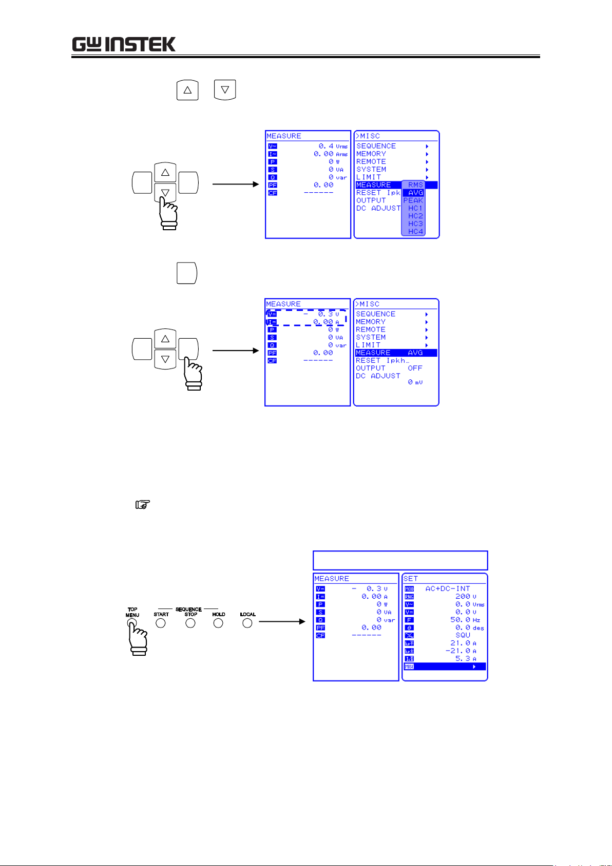
APS-1102A User Manual
4-14
ENTERCANCEL
ENTER
ENTERCANCE L
4. Press the or key to move the cursor to the desired measurement display.
Select “AVG” to measure only the DC power source.
5. Press the
key to set the selected measurement display.
Although harmonic current measurement (HC1 to HC4) is also displayed in the selection box,
this cannot be selected when in AC+DC mode. When in AC internal mode (AC-INT),
harmonic current measurement can be selected only when the frequency setting is 50.0 Hz or
60.0 Hz.
See “4.3 Measurement of Harmonic Current”.
6. Press the TOP MENU key or CANCEL key to return to the SET menu screen.
APS-1102A
Page 87

4 ADVANCED OPERATION EXAMPLE
4-15
4.2 Measurement of Inrush Current
4.2.1 Inrush current
In such an electrical product as contains a capacitor input type rectifier circuit for the input power line,
a current that is larger than the rated current may flow for a short time immediately after the power
source switch is turned on. This current is called an “inrush current.”
If the power source is not able to supply such a large current, enough power is not supplied to the
product, and sometimes it does not start in the worst case.
On the other hand, when such a large current passes through the power source line, the supply voltage
is likely to decrease because of the voltage drop at the line impedance. There exists a standard to limit
this effect within a certain level.
Such a product should be driven by a power source with enough supply capacity
Example of an inrush current
An electric drill
(rated 100 V AC/350 W)
Upper: Voltage (100 V/div)
Lower: Inrush current (10 A/div)
Even in a small electric drill, an inrush current of 14 Apk flows right after the power source is turned
on. Since the rated current is 3.5 A, this represents a fourfold increase in the current flow.
The APS-1102A can supply four times as a large peaked current as the maximum current supporting
such a usage. There is no need to use a power source with an extra large capacity in order to supply the
inrush current (for a capacitor input circuit of CF = 4 or less).
The initial phase of the output AC voltage is adjustable from 0.0 to 359.9 (in 0.1 steps), so the user
can monitor how the current inrushes in the load under various phase conditions. The peak current
hold measurement function enables the measurement of the maximum peak value for the current
flowing at that time. The measurement value of the peak current is reference value.
When measuring the inrush current, set the peak current limiter to the maximum value. If the limiter
setting is lowered, the inrush current measurement may be incorrect.
APS-1102A
Page 88
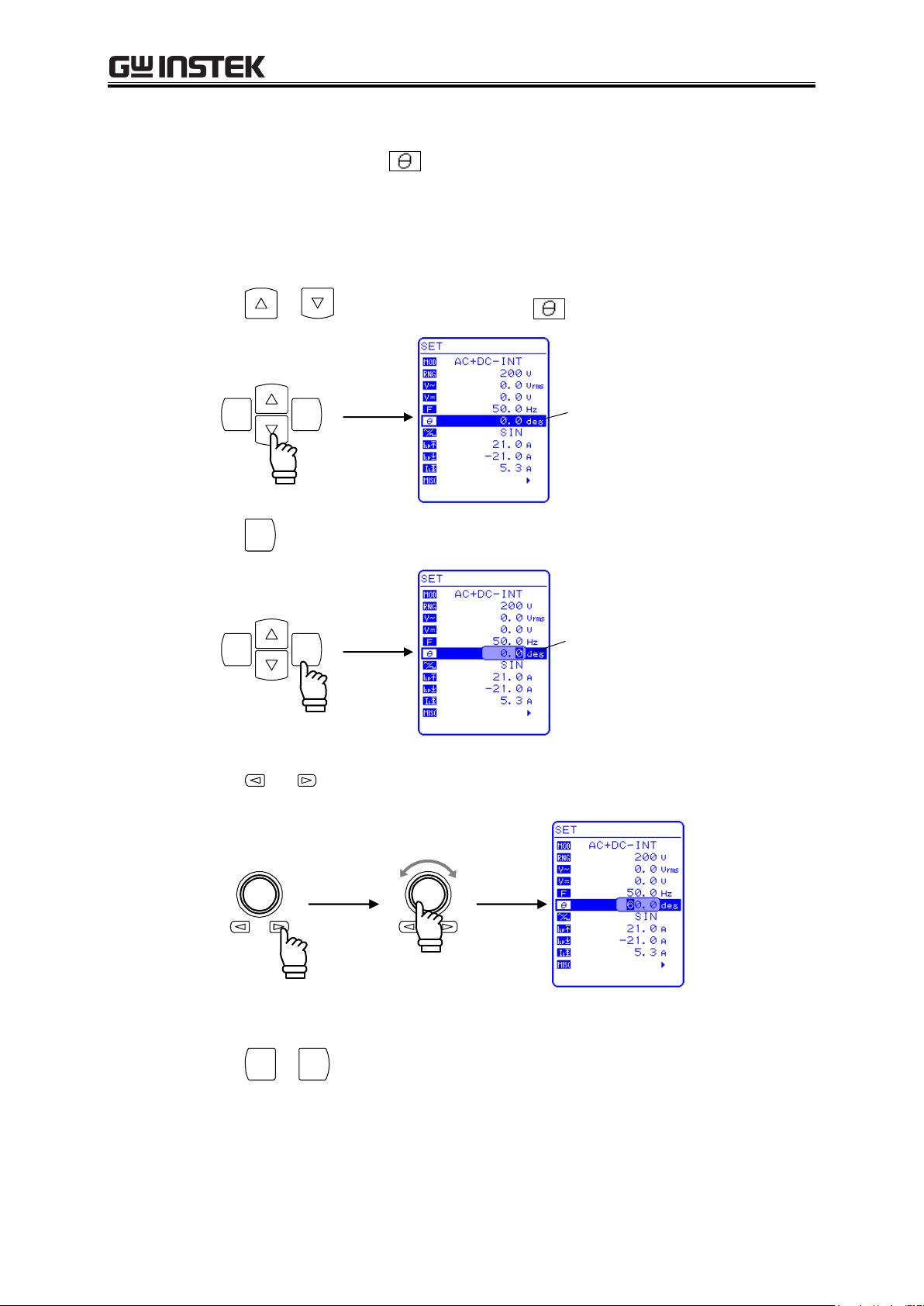
APS-1102A User Manual
4-16
ENTERCANCE L
Cursor
ENTER
ENTERCANCE L
Modification box
CANCE L
ENTER
Increase
Decrease
4.2.2 Set phase at output on
To set the phase at output on, select “Phase at output on” in the SET menu and set a numerical
value.
Before changing the phase at output on, set output off.
Operation steps
1. Press the or key to move the cursor to the icon.
2. Press the
key to display the modification box.
3. Press the and keys to move the cursor to the digit to be changed, turn the MODIFY dial
and set a numerical value. The set value will be reflected in output immediately.
4. Press the
APS-1102A
or
key to close the modification box.
Page 89

4 ADVANCED OPERATION EXAMPLE
4-17
ENTER
ENTERCANCEL
Cursor
ENTER
ENTERCANCE L
Selection box
ENTER
ENTERCANCEL
4.2.3 Set measurement display to peak value
Set the displayed current measurement value to the peak value (PEAK).
To change the displayed current measurement value, select “MEASURE” in the MISC menu .
Operation steps
1. Press the or key to move the cursor to the icon, then press the
The MISC menu is displayed.
2. Press the or key to move the cursor to “MEASURE”, then press the
The selection box is displayed.
key.
key.
3. Press the or key to move the cursor to “PEAK”, then press the
key.
This sets the measurement display to the peak value (PEAK).
APS-1102A
Page 90

APS-1102A User Manual
4-18
Peak value
Peak hold value
ENTER
ENTERCANCE L
Cursor
4. Press the TOP MENU key or the CANCEL key to return to the SET menu screen.
The measured value window shows the peak value set in the measurement display.
4.2.4 Reset the peak current hold value
The APS-1102A includes a function that resets the peak current hold value.
A reset sets the peak current hold value to 0 Apk, and the maximum peak value of current is updated
until the next reset is performed.
The current peak value is reset automatically at power-on.
To reset the peak current hold value, select “MEASURE” in the MISC menu .
Operation steps
1. Press the or key to move the cursor to the icon, then press the
The MISC menu is displayed.
key.
APS-1102A
Page 91

4 ADVANCED OPERATION EXAMPLE
4-19
ENTER
ENTERCANCEL
EXEC box
ENTER
ENTERCANCEL
2. Press the or key to move the cursor to “RESET Ipkh…”, then press the
The EXEC box is displayed.
3. When “EXEC” is displayed, press the
key.
The peak current hold value is reset.
key.
4. Press the TOP MENU key or CANCEL key to return to the SET menu screen.
The peak current hold value shown in measured value window becomes 0 Apk.
APS-1102A
Page 92

APS-1102A User Manual
4-20
ENTER
ENTERCANCE L
Cursor
ENTER
ENTERCANCEL
Selection box
4.3 Measurement of Harmonic Current
Switching power sources are widely used in both consumer and industrial electrical products. The
capacitor input type rectifier circuits that are used with such input power lines have disadvantages such as
significant distortion of input current and a large amount of harmonic current. When a large amount of this
current flows in the power source line, the equipment may experience operation faults, such as voltage
distortion, which can cause the transformer to overheat, possibly resulting in a hazardous accident.
The APS-1102A includes a function for measuring harmonic current. This measurement does not
conform to the IEC or other standards.
This measurement can be performed only in AC-INT mode and when the fundamental wave (panel
frequency setting) is either 50 Hz or 60 Hz. Absolute values of harmonic current in RMS and their
percentages to the fundamental are displayed up to the 40th harmonics (2 kHz at 50 Hz fundamental).
The measurement value of harmonic current is reference value.
When harmonic current measurement is selected, RMS value, average DC, and peak value measurements
are not performed. If RMS value, average DC, or peak value has been set, harmonic current measurement
is not performed.
a) Changing to harmonic measurement window
To view the harmonic measurement window, select “MEASURE” in the MISC menu .
Operation steps
1. Press the
or key to move the cursor to the icon, then press the
The MISC menu is displayed.
2. Press the
or key to move the cursor to “MEASURE”, then press the
The selection box is displayed.
key.
key.
APS-1102A
Page 93

4 ADVANCED OPERATION EXAMPLE
4-21
ENTER
ENTERCANCE L
3. Press the
the
or key to move the cursor to the harmonic order to be displayed, then press
key.
When HC1 to HC4 have been selected as the displayed measurements, the following harmonic
current measured values are displayed.
The displayed harmonic order (XXth) changes according to these ranges, and 10 lines of
measurement data are displayed in each range.
HC1: 1st to 10th
HC2: 11th to 20th
HC3: 21st to 30th
HC4: 31st to 40th
Figure 4-4. Example of Harmonic Measurement Window Display
4. Press the
5. Press the
key to switch the HC1, HC2, HC3, and HC4 screens.
or
key to end harmonic measurement and return to the TOP MENU (normal display).
APS-1102A
Page 94

APS-1102A User Manual
4-22
4.4 Using the Sequence Function
4.4.1 Sequence operations
When the sequence function of the APS-1102A is used, the pattern to be output can be freely
programmed.
For example, if a series of voltage change patterns that will be used in voltage variation tests for car
electronics are programmed in advance, the output will change according to the sequence, so the test can
be completed in one series of operations.
In the sequence operation programming, DC, sine waves, and square waves, which are built in the
APS-1102A, and arbitrary waveform (16 types) captured via the USB interface is able to use. Maximum
step number is 255 (minimum step time is 0.1 ms). In each step, waveform, level, and duration time can be
set and constant/keep/sweep can be chosen. In addition, sequences can be repeated from 1 to 999 times (or
continuously). The APS-1102A is also equipped with other functions, such as for branching to a specified
step during a sequence operation, and for starting, stopping, or holding a sequence operation.
Data is saved to sequence memory automatically.
These sequence functions can be used in AC-INT mode or AC+DC-INT mode.
Number of sequences: Retained for each operation mode (AC/AC+DC) and each output voltage
range (100 V/200 V).
Number of steps: 1 to 255 (per sequence)
Step time: 0.1 ms to 999.9999 s (resolution 0.1 ms or 0.0001 s)
Operations within step: Constant, keep, or linear sweep
Parameter: DC voltage
synchronized output (2 bits)
Jump times: 1 to 999 or infinite
Sequence control: Start: Starts a sequence.
Stop: Stops a sequence.
Hold: Maintains current settings. This is restarted when a
Branch: Branches to the specified step.
Note The setting ranges for AC voltage and DC voltage are determined by the output voltage ranges
set when editing the sequence data.
Sequence control cannot be executed when the output is off.
Note
, AC voltage
Note
, frequency, waveform, phase (start, end), step
sequence is started.
APS-1102A
Page 95

4 ADVANCED OPERATION EXAMPLE
4-23
[Output parameters]
DC voltage
AC voltage
Frequency
Waveform (SIN/SQU/ARB1 to ARB16)
Phase (start phase)
Step synchronized output
[Step operation types]
The following parameters are provided to specify actions related to output at
each step.
Constant (CONST: The values specified by output parameters are output.)
Sweep (SWEEP: A linear sweep is performed from the previous step
end value to the value specified by the output
parameter, using the specified step time.)
Keep (KEEP
Note
: The previous step end value is output.)
a) Sequence
A sequence is comprised of a combination of at least two steps (the minimum unit is one step).
b) Step
Step execution parameters and step transition parameters are specified for each step. When sequence
execution is not performed (i.e., during normal output mode), these parameters are specified in the
same way. Thereafter, the normal output mode is called normal output step. In the descriptions below,
the step parameters are enclosed in brackets ([ ]).
The step execution parameters specify the output and related actions in each step.
Table4-4. Step Execution Parameters
Note When the [step operation type] is KEEP, the [output parameter] setting is ignored.
APS-1102A
Page 96
APS-1102A User Manual
4-24
[Step time]
Specified in time
[Step end phase]
Sets step end phase as enabled or disabled.
[Step end]
The following parameters are provided to specify the action at the end of the
step.
Continue sequence (CONT)
Hold (HOLD)
Idle (STOP)
[Jump step]
The following parameters are provided to specify the destination step when a
jump occurs after ending the current step.
Jump to an arbitrary number step (1 to 255)
Jump to the next number step (0)
[Jump times]
The following parameters set a loop for jumping to the step specified by [jump
step] the specified number of times.
The following parameters are provided to specify the jump times.
Specified number (1 to 999)
Infinite times (0)
[Branch step]
The following parameters are provided to specify the destination step for
branch control.
Change to arbitrary step number (1 to 255)
Continue step processing without changing (0)
The step transition parameters specify the next step and its timing.
Table4-5. Step Transition Parameters
When start is commanded during normal output while in idle mode, step 1 is executed, then the step jumps
according to the specified sequence.
If the [jump step] has not been specified (= 0), the step jumps according to the sequence of step numbers,
but when the [jump step] has been specified (= 1 to 255), the step jumps to the step specified by that
parameter.
A step ends when the time specified by the [step time] has elapsed. If the [step end phase] has been
specified as enabled, the step ends when the [step end phase] value becomes (0) after the [step time] has
elapsed.
If both [step end] and [jump step] have been specified, the [step end] specification takes priority.
APS-1102A
Page 97
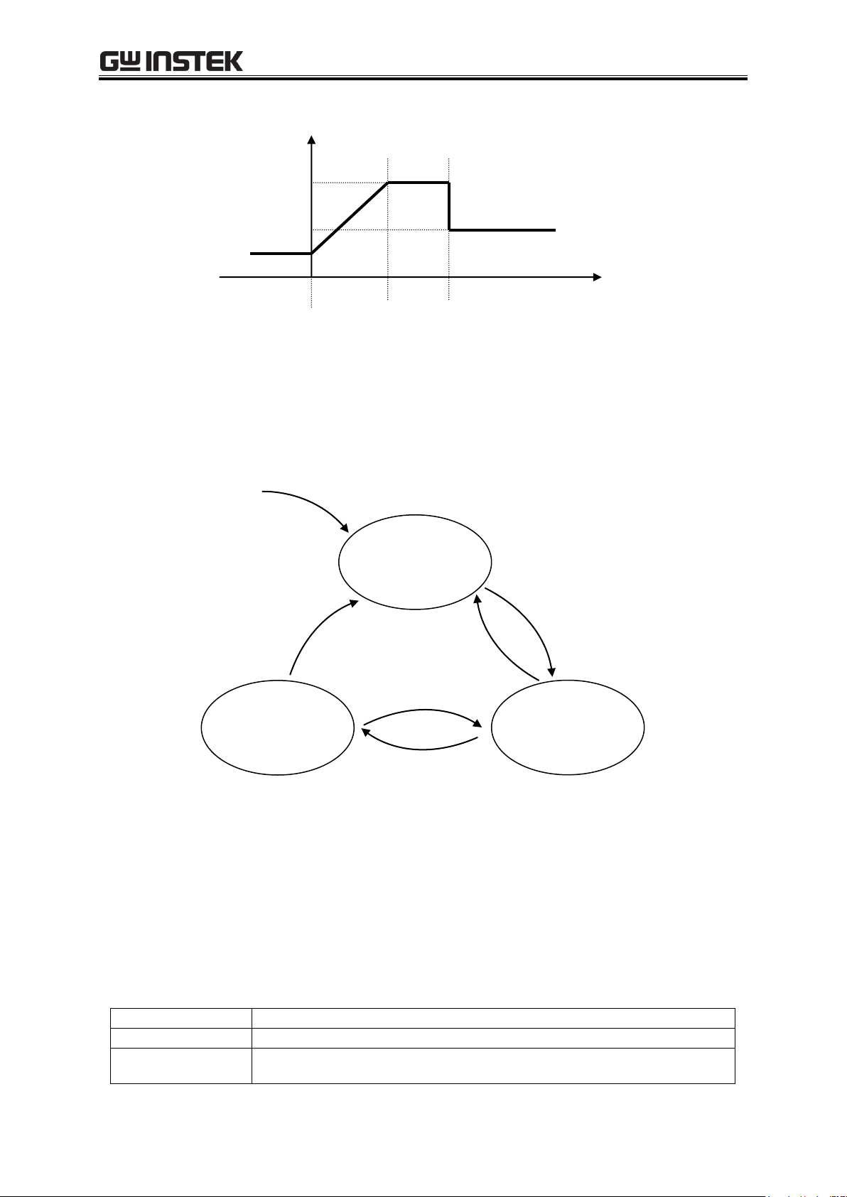
4 ADVANCED OPERATION EXAMPLE
4-25
<START>
Output parameters
Time
Normal output
step
Step 1
Step 2
Step 3
Steps 1, 2
Step 3
Idle mode
(normal output)
Output on
Run mode
(sequence
execution)
Hold mode
(pause)
<Start>
<Stop>
<Stop>
<Hold>
<Start>
Idle mode
Mode during normal output.
Run mode
Mode during sequence execution.
Hold mode
Sequence pause mode.
Maintains output at time when <Hold> was set.
An example of basic step transitions is shown below.
Figure 4-5. Example of Basic Step Transitions
c) Sequence mode
Figure 4-6 shows a mode transition diagram for sequence operations.
Figure 4-6. Block Diagram of Sequence Mode Transitions
---------- Notes -----------------------------------------------------------------------------------------------------
Modes also change according to the [step end] specification.
-------------------------------------------------------------------------------------------------------------------------
Table4-6. Sequence Modes
APS-1102A
Page 98

APS-1102A User Manual
4-26
<Start>
Sets Run mode.
When changing from Idle mode, the operation goes to step 1 when <Start> is set,
and the sequence is started.
When changing from Hold mode, the sequence is resumed from where it was
stopped when <Hold> was set.
When <Hold> mode is set by the [step end] parameter, the sequence is resumed at
the step specified by [jump step] when <Start> is set.
<Hold>
Changes from Run mode to Hold mode.
<Stop>
Changes to Idle mode.
Immediately changes to normal output step.
At that time, the values when <Stop> occurred are retained to the normal output step
[output parameter].
If it is tried to set the output voltage at <Stop> to exceed the setting range limit, then
the setting will change to 0 V. If it is tried to set the frequency out of the setting
range limit, then the setting will change to the lower limit of the setting range. The
output will turn off in these cases.
<Branch>
Changes to the step specified by [branch step].
Changes from the output at the time when <Branch> occurred to the [branch step].
<Hold>
<Start>
Step 2 settings
• Final value
• Step time
Step 1
Step 2
Time
Step 3
Output parameter
Step 1
Step 2
Step 5
Output parameter
Step 2 settings
• Final value
• Step time
• Branch step 5
Time
Step 5 settings
• Final value from previous step is used
<Branch>
d) Sequence control
The following describes how sequence operations are controlled. Sequence control operations are
indicated in triangular brackets (< >).
Table4-7. Sequence Control
Figure 4-7. Example of Sequence Operation from Hold Mode to <Start>
Figure 4-8. Example of Sequence Operation at <Branch>
APS-1102A
Page 99
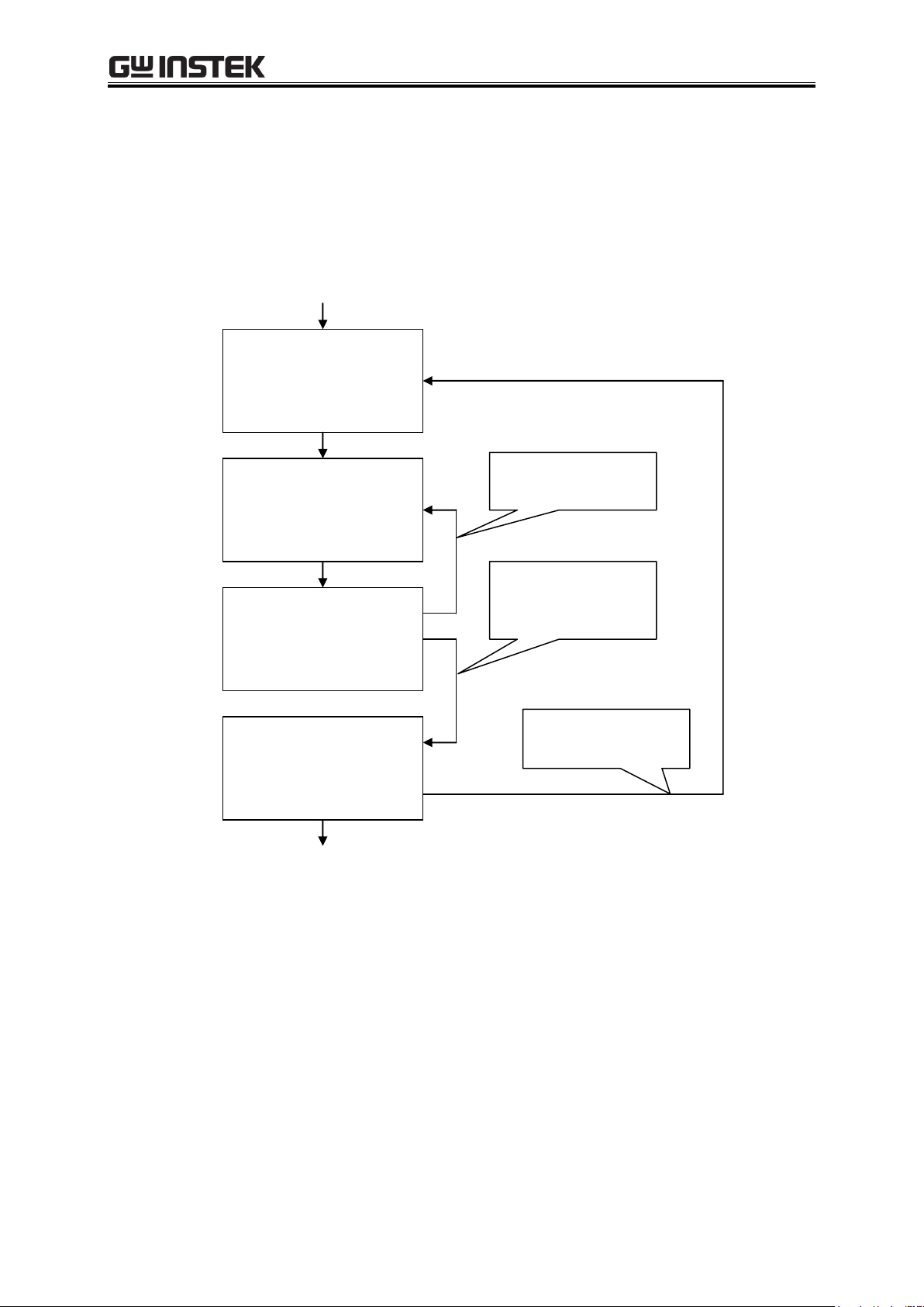
4 ADVANCED OPERATION EXAMPLE
4-27
Step 4
[jump step] 0
[jump times] NoCare
Step 5
[jump step] 0
[jump times] NoCare
Step 6
[jump step] 5
[jump times] 10
Step7
[jump step] 4
[jump times] 3
Specified times (10 times)
changes to [jump step]
Changes to next step,
after specified times
(10 times) jump
Specified times (3 times)
changes to [jump step]
e) Sequence loop
Either an entire sequence or a block of any number of steps within a sequence can be used as a
sequence loop. The loop is implemented based on the [jump step] and [jump times] parameters
specified for each step. The jump counter, which counts the number of jumps, functions within each
step to retain a count, so multiple loops can be implemented.
Figure 4-9 below illustrates the loop specification method and the step transitions.
Figure 4-9. Loop Specification Method and Step Transition Example
---------- Notes -----------------------------------------------------------------------------------------------------
[jump times] indicates the number of jumps. Consequently, loop times = jump times + 1.
In the example above, 10 jump times are specified for Step 6, so Step 5 and Step 6 are
executed 11 times.
-------------------------------------------------------------------------------------------------------------------------
APS-1102A
Page 100

APS-1102A User Manual
4-28
Step 1
Step 2
Step 3
Step synchronized output
Time
Step 4
Step 5
L
H
[Step synchronized output]
L H L L H
Value set for this step
Set value is
retained.
SWEEP
Time set by [step time]
Wait time for
0 phase
f) Step synchronized output
The code that is specified in the step being executed is output to the external control I/O connector.
However, “L” is output during a normal output step.
Figure 4-10. Example of Step Synchronized Output
g) Step end phase setting
When the step end phase is set as enabled, the step execution time is as described below.
The step execution time = Set step time + Time for superimposed AC phase to become 0
After the set step time elapses, the setting for that step is retained in the subsequent operation.
APS-1102A
Figure 4-11. Sequence Operation during Wait for Phase 0°
 Loading...