

Page 1

Arbitrary Function Generator
AFG-3000 Series
USER MANUAL
GW INSTEK PART NO. 82FG-30820E01
ISO-9001 CERTIFIED MANUFACTURER
Page 2

October 2010 edition
This manual contains proprietary information, which is protected by
copyright. All rights are reserved. No part of this manual may be
photocopied, reproduced or translated to another language without
prior written consent of Good Will Corporation.
The information in this manual was correct at the time of printing.
However, Good Will continues to improve its products and therefore
reserves the right to change the specifications, equipment, and
maintenance procedures at any time without notice.
Good Will Instrument Co., Ltd.
No. 7-1, Jhongsing Rd., Tucheng City, Taipei County 236, Taiwan.
Page 3

TABLE OF CONTENTS
Table of Contents
SAFETY INSTRUCTIONS .................................. 6
GETTING STARTED ........................................ 11
Main Features ................................................................... 11
Panel Overview .................................................................. 13
Setting up the Function Generator .................................... 19
QUICK REFERENCE ....................................... 21
How to use the Digital Inputs ........................................... 23
How to use the Help Menu ............................................... 24
Selecting a Waveform ........................................................ 26
Modulation ........................................................................ 28
Sweep ................................................................................ 32
Burst ................................................................................. 33
ARB ................................................................................... 35
Utility Menu ...................................................................... 39
Menu Tree ......................................................................... 42
Default Settings ................................................................ 53
OPERATION ................................................... 55
Select a Waveform ............................................................. 56
MODULATION ............................................... 65
Amplitude Modulation (AM) ............................................. 67
Frequency Modulation (FM) .............................................. 75
Frequency Shift Keying (FSK) Modulation .......................... 83
Pulse Width Modulation .................................................... 90
Frequency Sweep ............................................................... 97
Burst Mode ..................................................................... 108
3
Page 4

AFG-3000 Series User Manual
SECONDARY SYSTEM FUNCTION SETTINGS
..................................................................... 121
Save and Recall ............................................................... 122
Selecting the Remote Interface ........................................ 125
System and Settings ........................................................ 129
ARBITRARY WAVEFORMS ............................ 137
Inserting Built-In Waveforms ........................................... 138
Display an Arbitrary Waveform ........................................ 151
Editing an Arbitrary Waveform ......................................... 158
Output an Arbitrary Waveform ......................................... 168
Saving/Loading an Arbitrary Waveform ............................ 174
REMOTE INTERFACE ................................... 182
Establishing a Remote Connection .................................. 183
Command Syntax ............................................................. 188
Command List ................................................................. 193
System Commands .......................................................... 196
Status Register Commands .............................................. 200
Interface Configuration Commands ................................. 203
Apply Commands ............................................................ 204
Output Commands .......................................................... 211
Pulse Configuration Commands ...................................... 221
Amplitude Modulation (AM) Commands ......................... 223
AM Overview ................................................................... 223
Frequency Modulation (FM) Commands .......................... 228
FM Overview ................................................................... 228
Frequency-Shift Keying (FSK) Commands ........................ 233
FSK Overview .................................................................. 233
Pulse Width Modulation (PWM) Commands ................... 236
PWM Overview ................................................................ 236
Frequency Sweep Commands ........................................... 241
Sweep Overview .............................................................. 241
Burst Mode Commands ................................................... 251
4
Page 5

TABLE OF CONTENTS
Burst Mode Overview ...................................................... 251
Arbitrary Waveform Commands ....................................... 262
Arbitrary Waveform Overview .......................................... 262
Save and Recall Commands ............................................. 273
Error Messages ............................................................... 275
SCPI Status Registers ...................................................... 289
APPENDIX .................................................... 295
Fuse Replacement ........................................................... 295
AFG-3000 Series Specifications ....................................... 296
EC Declaration of Conformity .......................................... 302
INDEX .......................................................... 303
5
Page 6
AFG-3000 Series User Manual
SAFETY INSTRUCTIONS
This chapter contains important safety instructions
that should be followed when operating and
storing the function generator. Read the following
before any operation to ensure your safety and to
keep the function generator in the best condition.
Safety Symbols
These safety symbols may appear in this manual or on the
instrument.
WARNING
CAUTION
6
Warning: Identifies conditions or practices that
could result in injury or loss of life.
Caution: Identifies conditions or practices that
could result in damage to the function generator or
to other objects or property.
DANGER High Voltage
Attention: Refer to the Manual
Protective Conductor Terminal
Earth (Ground) Terminal
DANGER Hot Surface
Page 7
SAFETY INSTRUCTIONS
Double Insulated
Do not dispose electronic equipment as unsorted
municipal waste. Please use a separate collection
facility or contact the supplier from which this
instrument was purchased.
Safety Guidelines
General
Guideline
CAUTION
Power Supply
WARNING
Do not place heavy objects on the instrument.
Do not place flammable objects on the
Avoid severe impact or rough handling that
Avoid discharges of static electricity on or near
Use only mating connectors, not bare wires, for
The instrument should only be disassembled by
(Measurement categories) EN 61010-1:2001 specifies the
measurement categories and their requirements as follows. The
AFG-3000 falls under category II.
Measurement category IV is for measurement performed at the
Measurement category III is for measurement performed in a
Measurement category II is for measurement performed on
Measurement category I is for measurements performed on
AC Input voltage: 100 ~ 240V AC, 50 ~ 60Hz.
Connect the protective grounding conductor of
instrument.
may damage the function generator.
the function generator.
the terminals.
a qualified technician.
source of a low-voltage installation.
building installation.
circuits directly connected to a low voltage installation.
circuits not directly connected to Mains.
the AC power cord to an earth ground to
prevent electric shock.
7
Page 8
AFG-3000 Series User Manual
Fuse
WARNING
Cleaning the
function
generator
Operation
Environment
Fuse type: T0.63A/250V.
Only qualified technicians should replace the
fuse.
To ensure fire protection, replace the fuse only
with the specified type and rating.
Disconnect the power cord and all test leads
before replacing the fuse.
Make sure the cause of fuse blowout is fixed
before replacing the fuse.
Disconnect the power cord before cleaning the
function generator.
Use a soft cloth dampened in a solution of mild
detergent and water. Do not spray any liquid
into the function generator.
Do not use chemicals containing harsh products
such as benzene, toluene, xylene, and acetone.
Location: Indoor, no direct sunlight, dust free,
almost non-conductive pollution (Note below)
and avoid strong magnetic fields.
Relative Humidity: < 80%
Altitude: < 2000m
Temperature: 0°C to 40°C
8
Page 9

SAFETY INSTRUCTIONS
Storage
environment
Disposal
(Pollution Degree) EN 61010-1:2001 specifies pollution degrees and
their requirements as follows. The function generator falls under
degree 2.
Pollution refers to “addition of foreign matter, solid, liquid, or
gaseous (ionized gases), that may produce a reduction of dielectric
strength or surface resistivity”.
Pollution degree 1: No pollution or only dry, non-conductive
pollution occurs. The pollution has no influence.
Pollution degree 2: Normally only non-conductive pollution
occurs. Occasionally, however, a temporary conductivity caused
by condensation must be expected.
Pollution degree 3: Conductive pollution occurs, or dry, non-
conductive pollution occurs which becomes conductive due to
condensation which is expected. In such conditions, equipment
is normally protected against exposure to direct sunlight,
precipitation, and full wind pressure, but neither temperature
nor humidity is controlled.
Location: Indoor
Relative Humidity: < 70%
Temperature: -10°C to 70°C
Do not dispose this instrument as unsorted
municipal waste. Please use a separate collection
facility or contact the supplier from which this
instrument was purchased. Please make sure
discarded electrical waste is properly recycled to
reduce environmental impact.
9
Page 10
AFG-3000 Series User Manual
Power cord for the United Kingdom
When using the function generator in the United Kingdom, make sure the
power cord meets the following safety instructions.
NOTE: This lead/appliance must only be wired by competent persons
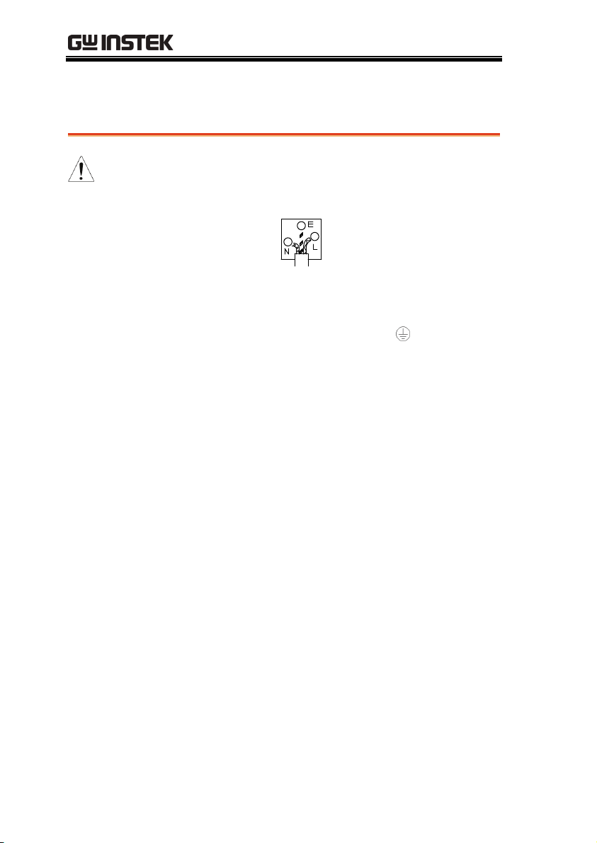
WARNING: THIS APPLIANCE MUST BE EARTHED
IMPORTANT: The wires in this lead are coloured in accordance with the
following code:
Green/ Yellow: Earth
Blue: Neutral
Brown: Live (Phase)
As the colours of the wires in main leads may not correspond with the
coloured marking identified in your plug/appliance, proceed as follows:
The wire which is coloured Green & Yellow must be connected to the Earth
terminal marked with either the letter E, the earth symbol
Green/Green & Yellow.
The wire which is coloured Blue must be connected to the terminal which is
marked with the letter N or coloured Blue or Black.
The wire which is coloured Brown must be connected to the terminal
marked with the letter L or P or coloured Brown or Red.
If in doubt, consult the instructions provided with the equipment or contact
the supplier.
This cable/appliance should be protected by a suitably rated and approved
HBC mains fuse: refer to the rating information on the equipment and/or
user instructions for details. As a guide, a cable of 0.75mm
protected by a 3A or 5A fuse. Larger conductors would normally require
13A types, depending on the connection method used.
Any exposed wiring from a cable, plug or connection that is engaged in a
live socket is extremely hazardous. If a cable or plug is deemed hazardous,
turn off the mains power and remove the cable, any fuses and fuse
assemblies. All hazardous wiring must be immediately destroyed and
replaced in accordance to the above standard.
or coloured
2
should be
10
Page 11

GETTING STARTED
GETTING STARTED
The Getting started chapter introduces the
function generator’s main features, appearance, set
up procedure and power-up.
Main Features
Model name Frequency bandwidth
AFG-3081 80MHz
AFG-3051 50MHz
Performance
DDS Function Generator series
1μHz high frequency resolution maintained at
full range
1ppm frequency stability
Full Function Arbitrary Waveform Capability
200 MSa/s sample rate
100 MSa/s repetition rate
1 M-point waveform length
16-bit amplitude resolution
Ten 1M waveform memories
True waveform output to display
User define output section
User defined marker output section
D W R (Direct Waveform Reconstruction)
capability
Waveform editing capability sans PC
N Cycle and Infinite output mode selectable
11
Page 12

AFG-3000 Series User Manual
-60dBc low distortion sine wave
Features
Interface
Sine, Square, Ramp, Pulse, Noise, Sinc standard
waveforms
Internal and external LIN/LOG sweep with
marker output
Int/Ext AM, FM, PWM, FSK modulation
Modulation/sweep signal output
Burst function with internal and external
triggers without marker output
Store/recall 10 groups of setting memories
Output overload protection
GPIB, RS232, USB standard interfaces
4.3 inch Color TFT LCD (480 × 272) Graphical
User Interface.
AWES (Arbitrary Waveform Editing Software)
PC software
12
Page 13
GETTING STARTED
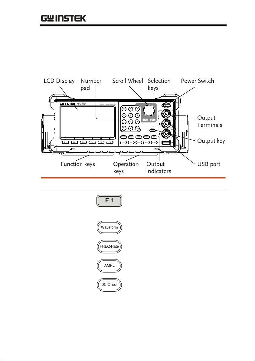
Panel Overview
Front Panel
LCD display
TFT color LCD display, 480 x 272 resolution.
Function keys:
F1~F6
Operation keys
Activates the functions which
appear in the bottom of the LCD
display.
Waveform is used to select a
waveform type.
The FREQ/Rate key is used to set
the frequency or sample rate
AMPL sets the waveform
amplitude.
Sets the DC offset.
13
Page 14
AFG-3000 Series User Manual
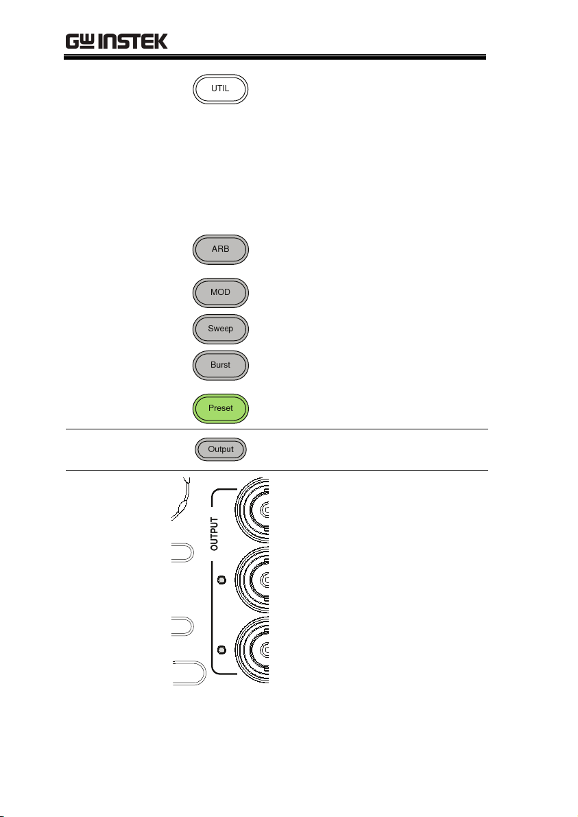
Preset
Output key
The UTIL key is used to access the
save and recall options, set the
remote interface (USB, GPIB,
RS232), use DSO link, update and
view the firmware version, access
the calibration options, output
impedance settings, set the
language and access the help
menu.
ARB is used to set the arbitrary
waveform parameters.
The MOD, Sweep and Burst keys
are used to set the modulation,
sweep and burst settings and
parameters.
The preset key is used to recall a
preset state.
The Output key is used to turn on
or off the waveform output.
Output
indicators
When an Output indicator is
green, it indicates that the output
is active.
14
Page 15
GETTING STARTED
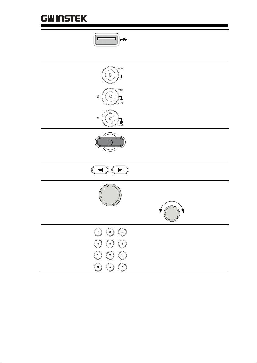
USB host
connector
Output terminals
Standby key
Selection keys
Scroll Wheel
The USB Host connector is used
to save and restore waveform
data and images, as well as
update the firmware.
Modulation output terminal.
The SYNC output terminal. 50Ω
output impedance.
The primary output terminal. 50Ω
output impedance.
The standby key is used to turn
the function generator on (green)
or to put the function generator
into standby mode (red).
Used to select digits when editing
parameters.
The scroll wheel is used to edit
values and parameters.
Keypad
Decrease
The digital keypad is used to
Increase
enter values and parameters. The
keypad is often used in
conjunction with the selection
keys and variable knob.
15
Page 16
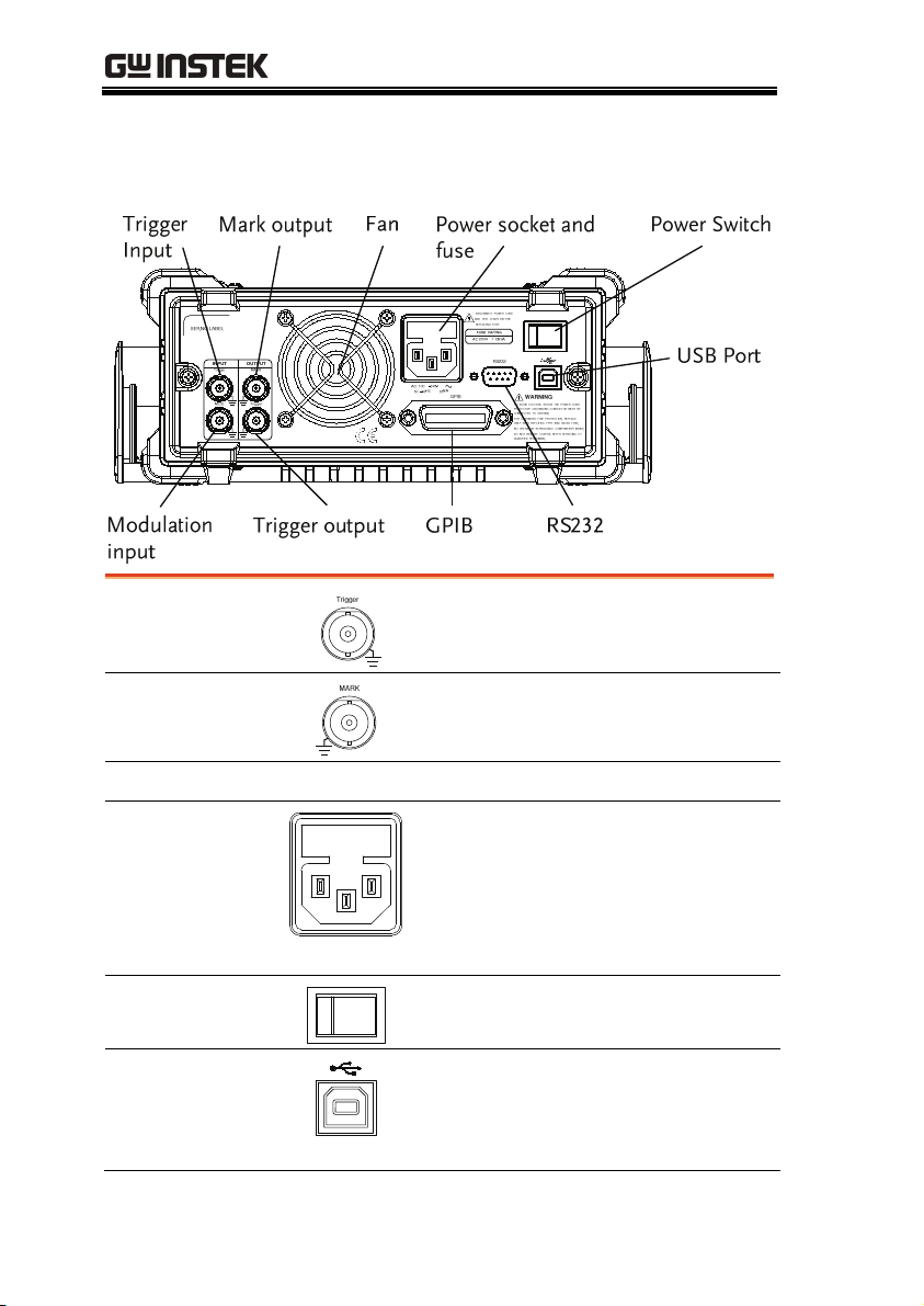
Rear Panel
Trigger input
AFG-3000 Series User Manual
External trigger input. Used to
receive external trigger signals.
MARK output
Mark output signal. Used for Sweep
and ARB mode only.
Fan
Power Socket
Input and fuse
Power input: 100~240V AC
50~60Hz.
Fuse: T0.63A/250V
For the fuse replacement procedure,
see page 295.
Power Switch
USB port
Main power switch.
The Mini-B type USB connector is
used to connect the function
generator to a PC for remote
control.
16
Page 17
GETTING STARTED
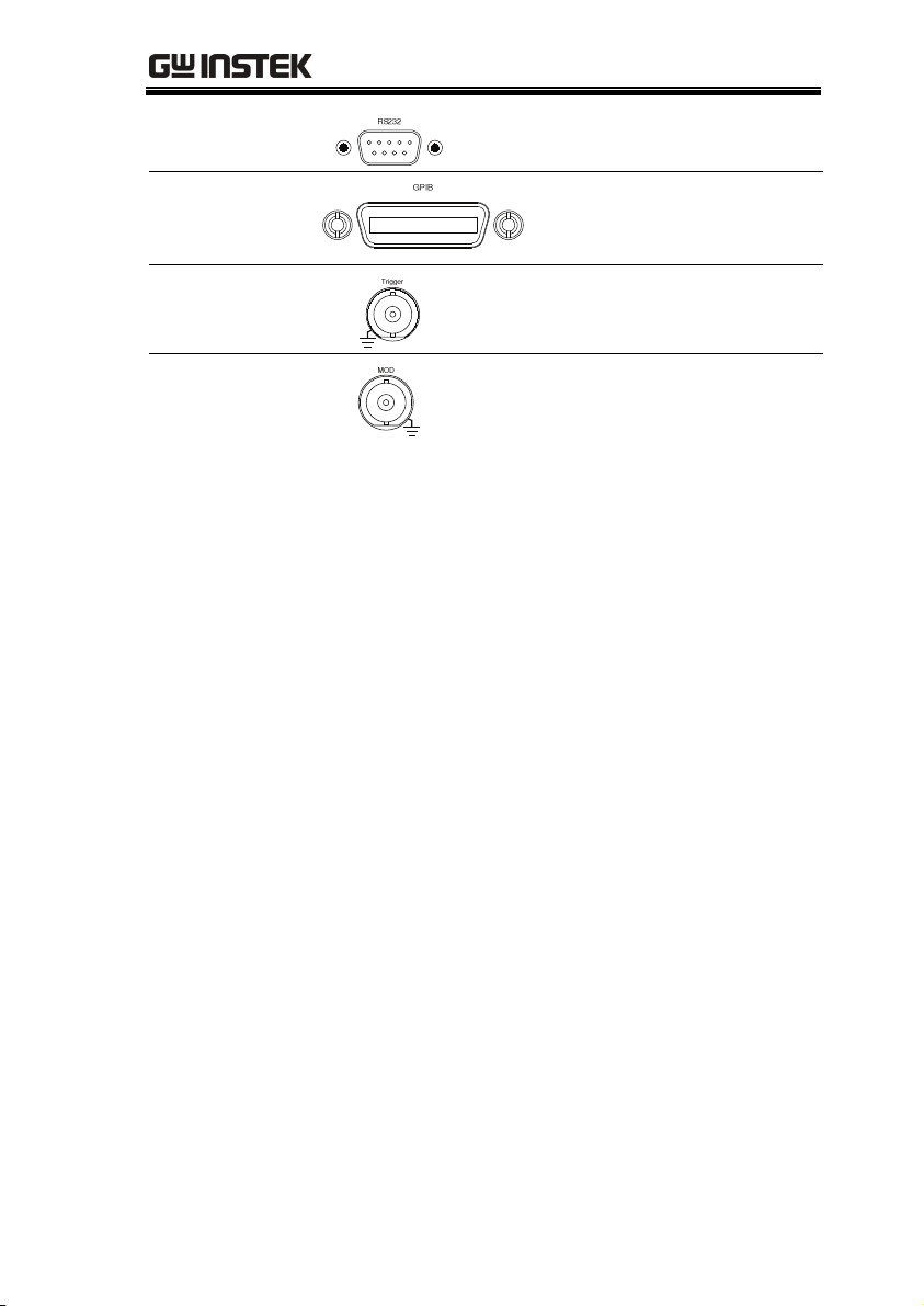
RS232 port
GPIB
Trigger output
MOD input
9 pin female RS232 socket used for
PC remote control.
24 pin female GPIB
connector for PC remote
control.
Trigger output terminal.
Modulation input terminal.
17
Page 18

AFG-3000 Series User Manual
Display
Parameter
Windows
Status Tabs Shows the status of MOD, Sweep and Burst modes.
The Parameter display and edit window.
Waveform Disp l a y
The Waveform Display is used to output the
waveform on the display.
Soft Menu Keys
The function keys (F1~F6) below the Soft Menu
keys correspond to the soft keys.
18
Page 19

GETTING STARTED
Setting up the Function Generator
Background
This section describes how adjust the handle and
power up the function generator.
Adjusting the
stand
Pull out the handle
sideways and rotate
it.
Place AFG
horizontally,
Or tilt stand.
Place the handle
vertically to hand
carry.
19
Page 20
AFG-3000 Series User Manual
y
On
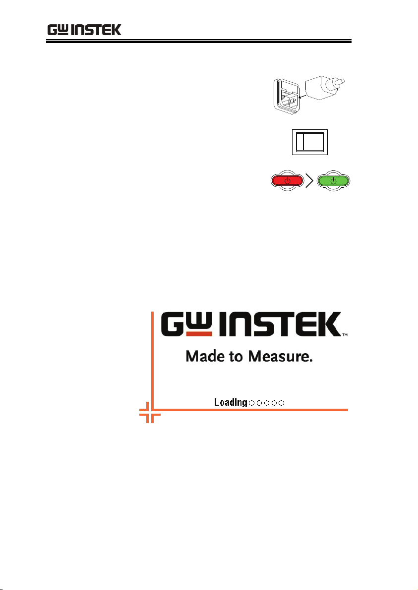
Power Up
1. Connect the power cord to
the socket on the rear
panel.
2. Turn on the power switch
on the rear panel.
3. Press and hold the Standby
key on the front panel to
turn the machine on. The
Standb
standby key will change
from red (standby) to green
(on).
4. When the standby key turns green, the
instrument will turn on showing a loading
screen.
The function generator in now ready to be used.
20
Page 21

QUICK REFERENCE
QUICK REFERENCE
This chapter lists operation shortcuts, built-in help coverage, and
default factory settings. Use this chapter as a handy reference for
instrument functions. This chapter is to be used as a quick reference,
for detailed explanations on parameters, settings and limitations,
please see the operation chapter (page 55) or specifications (page
296).
How to use the Digital Inputs ........................................... 23
How to use the Help Menu ............................................... 24
Selecting a Waveform ........................................................ 26
Square Wave ......................................................................... 26
Triangle Wave ....................................................................... 26
Sine Wave ............................................................................. 27
Modulation ........................................................................ 28
AM ........................................................................................ 28
FM ........................................................................................ 29
FSK Modulation.................................................................... 30
PWM Modulation ................................................................. 31
Sweep ................................................................................ 32
Burst ................................................................................. 33
ARB ................................................................................... 35
ARB – Add Built-In Waveform .............................................. 35
ARB – Add Built-In Waveform - Pulse .................................. 35
ARB - Add Point .................................................................... 36
ARB - Add Line ..................................................................... 36
ARB – Output Section .......................................................... 37
ARB – Output N Cycle .......................................................... 37
ARB – Output Infinite Cycles ............................................... 38
ARB – Output Markers ......................................................... 39
Utility Menu ...................................................................... 39
Save ...................................................................................... 39
Recall .................................................................................... 40
Interface GPIB ...................................................................... 40
Interface RS232 .................................................................... 41
21
Page 22

AFG-3000 Series User Manual
Interface USB ....................................................................... 41
Menu Tree ......................................................................... 42
Waveform ............................................................................. 43
ARB-Display .......................................................................... 43
ARB-Edit ............................................................................... 44
ARB-Built in .......................................................................... 45
ARB- Built in- More .............................................................. 46
ARB-Save .............................................................................. 47
ARB-Load .............................................................................. 47
ARB-Output .......................................................................... 48
MOD .................................................................................... 49
Sweep ................................................................................... 49
Sweep - More ....................................................................... 50
Burst – N Cycle .................................................................... 51
Burst - Gate .......................................................................... 51
UTIL ...................................................................................... 52
UTIL - Interface .................................................................... 52
Default Settings ................................................................. 53
22
Page 23
QUICK REFERENCE
How to use the Digital Inputs
Background
The AFG-3000 has three main types of digital
inputs: the number pad, selection keys and scroll
wheel. The following instructions will show you
how to use the digital inputs to edit parameters.
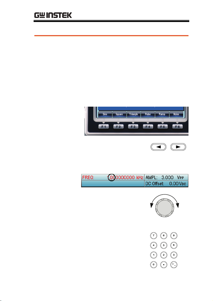
1. To select a menu item, press the
corresponding function keys below (F1~F6).
For example the function key F1 corresponds
to the Soft key “Sine”.
2. To edit a digital value, use
the selector key to move the
cursor to the digit that
needs to be edited.
3. Use the scroll wheel to edit
the digit under the cursor.
Clockwise increases the
value, counterclockwise
decreases the value.
4. Alternatively, the number
pad can be used to set the
value of a highlighted
parameter.
/
23
Page 24

AFG-3000 Series User Manual
How to use the Help Menu
Background
Every key and function has a detailed description
in the help menu.
1. Press UTIL.
2. Press System (F5).
3. Press Help (F3).
4. Use the scroll wheel to
navigate to a help item.
Press Select to choose the
item.
24
Keypad
Create Arbitrary
Waveform
Modulation
Function
Sweep Function Provides help on the Sweep
Provides help on any front panel
key that is pressed.
Provides help on creating
arbitrary waveforms.
Explains how to create
Modulated waveforms.
function.
Page 25
QUICK REFERENCE
Burst Function Provides help on the Burst
function.
DSO Link Provides help on DSO link.
Hardcopy Explains how to use the
Hardcopy function.
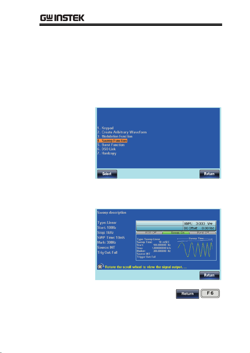
5. For example select item 4 to see help on the
sweep function.
6. Use the scroll wheel to navigate to each help
page.
7. Press F6 to return to the
previous menus.
25
Page 26

AFG-3000 Series User Manual
Selecting a Waveform
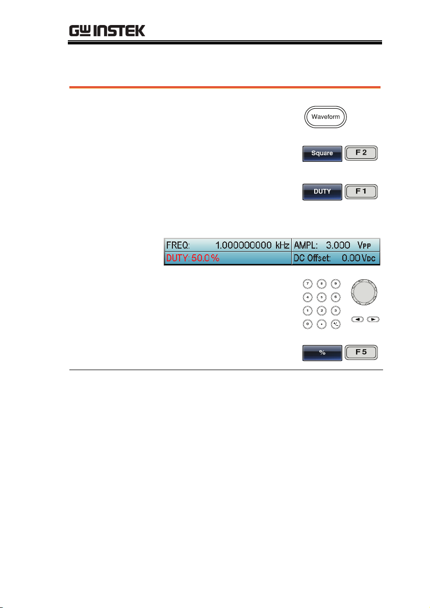
Square Wave
Example: Square Wave, 3Vpp, 75%Duty, 1 kHz
Output
Input: N/A
1. Press the Waveform
key and select
Square (F2).
2. Press Duty(F1),
followed by 7 + 5 +
%(F5)
3. Press the Freq/Rate
key, followed by 1 +
kHz (F5).
4. Press the AMPL
key, followed by 3 +
VPP (F6).
5. Press the output
key.
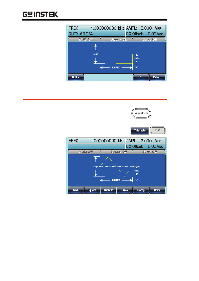
Triangle Wave
Example: Triangle Wave, 5Vpp,10kHz
Output
Input: N/A
26
1. Press the Waveform
key and select
Triangle (F3).
2. Press the Freq/Rate
key, followed by 1 +
0 + kHz (F5).
Page 27
QUICK REFERENCE
3. Press the AMPL
key, followed by 5
+VPP (F6).
4. Press the output
key.
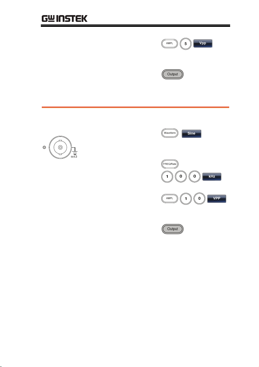
Sine Wave
Example: Sine Wave, 10Vpp,100kHz
Output
Input: N/A
1. Press the Waveform
key and select Sine
(F1).
2. Press the Freq/Rate
key, followed by 1 +
0 +0 + kHz (F5).
3. Press the AMPL
key, followed by 1 +
0 +VPP (F6).
4. Press the output
key.
27
Page 28
AFG-3000 Series User Manual
Modulation
AM
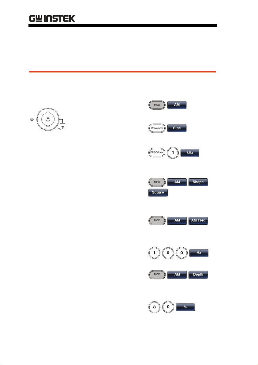
Example: AM modulation. 100Hz modulating square wave. 1kHz
Sine wave carrier. 80% modulation depth.
Output
Input: N/A
1. Press the MOD key
and select AM (F1).
2. Press Waveform
and select Sine (F1).
3. Press the Freq/Rate
key, followed by 1 +
kHz (F5).
4. Press the MOD key,
select AM (F1),
Shape (F4), Square
(F2).
5. Press the MOD key,
select AM (F1), AM
Freq (F3).
6. Press 1 + 0 + 0 + Hz
(F2).
7. Press the MOD key,
select AM (F1),
Depth (F2).
28
8. Press 8 + 0 + % (F1).
Page 29
QUICK REFERENCE
9. Press MOD, AM
(F1), Source (F1),
INT (F1).
10. Press the output
key.
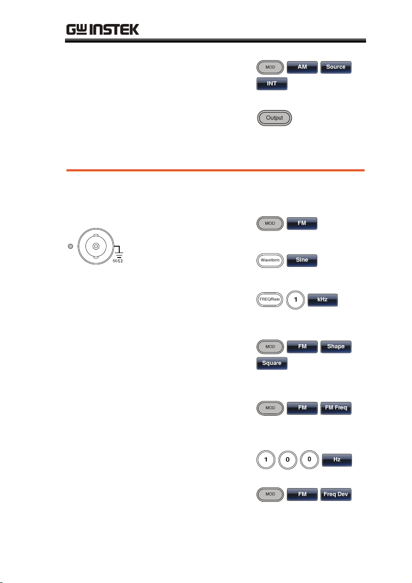
FM
Example: FM modulation. 100Hz modulating square wave. 1kHz
Sine wave carrier. 100 Hz frequency deviation. Internal Source.
Output
Input: N/A
1. Press the MOD key
and select FM (F2).
2. Press Waveform
and select Sine (F1).
3. Press the Freq/Rate
key, followed by 1 +
kHz (F5).
4. Press the MOD key,
select FM (F2),
Shape (F4), Square
(F2).
5. Press the MOD key,
select FM (F2), FM
Freq (F3).
6. Press 1 + 0 + 0 + Hz
(F2).
7. Press the MOD key,
select FM (F2), Freq
Dev (F2).
29
Page 30
AFG-3000 Series User Manual
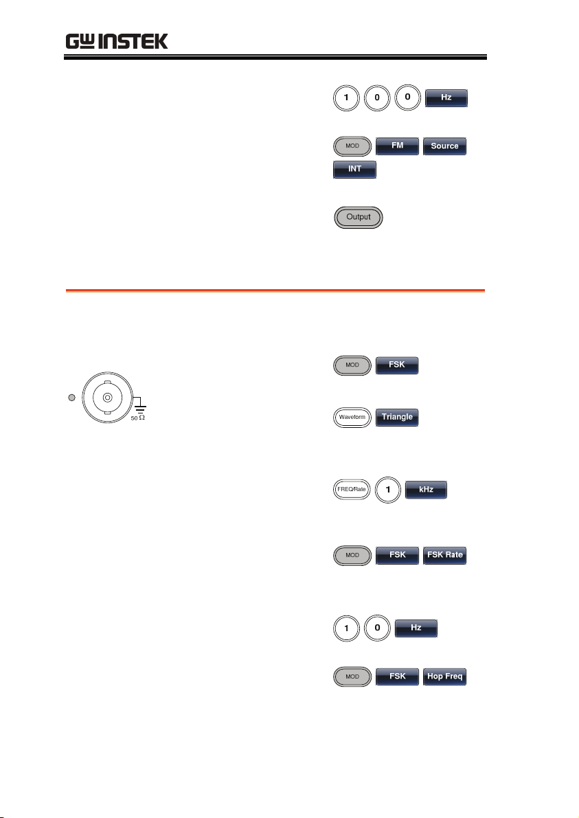
8. Press 1 + 0 + 0 + Hz
(F3).
9. Press MOD, FM
(F2), Source (F1),
INT (F1).
10. Press the output
key.
FSK Modulation
Example: FSK modulation. 100Hz Hop frequency. 1kHz Carrier
wave. Triangle wave. 10 Hz Rate. Internal Source.
Output
Input: N/A
1. Press the MOD key
and select FSK (F3).
2. Press Waveform
and select Triangle
(F3).
3. Press the Freq/Rate
key, followed by 1 +
kHz (F5).
30
4. Press the MOD key,
select FSK (F3), FSK
Rate (F3).
5. Press 1 + 0 + Hz
(F2).
6. Press the MOD key,
select FSK (F3), Hop
Freq (F2).
Page 31
QUICK REFERENCE
7. Press 1 + 0 + 0 + Hz
(F3).
8. Press MOD, FSK
(F3), Source (F1),
INT (F1).
9. Press the output
key.
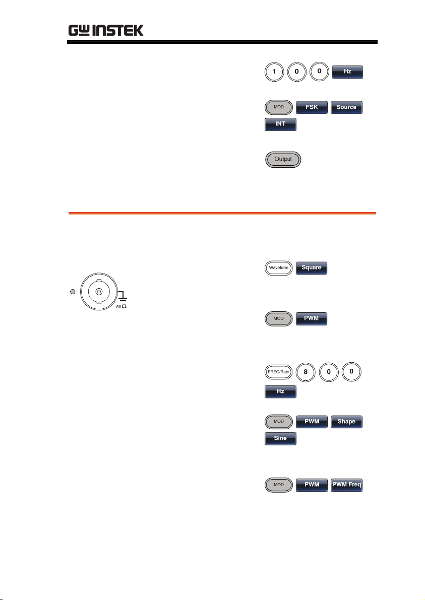
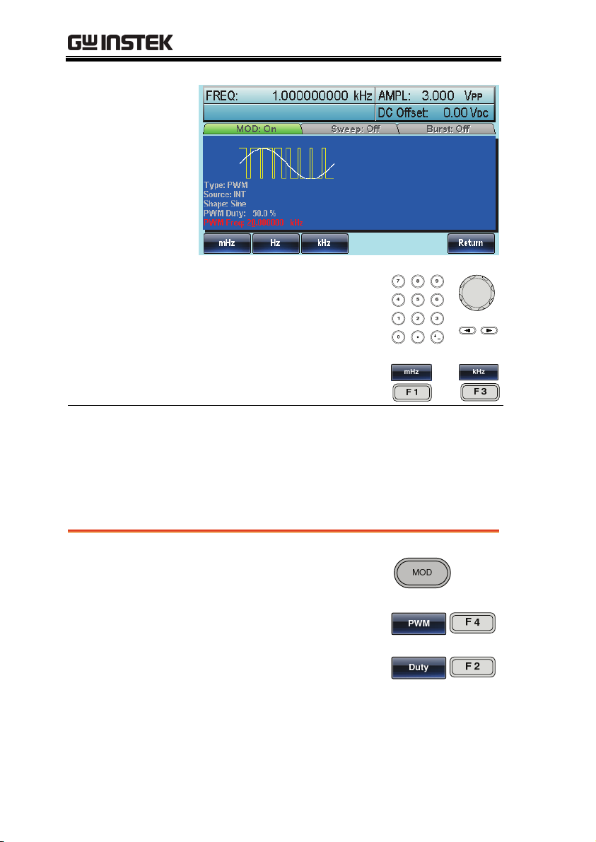
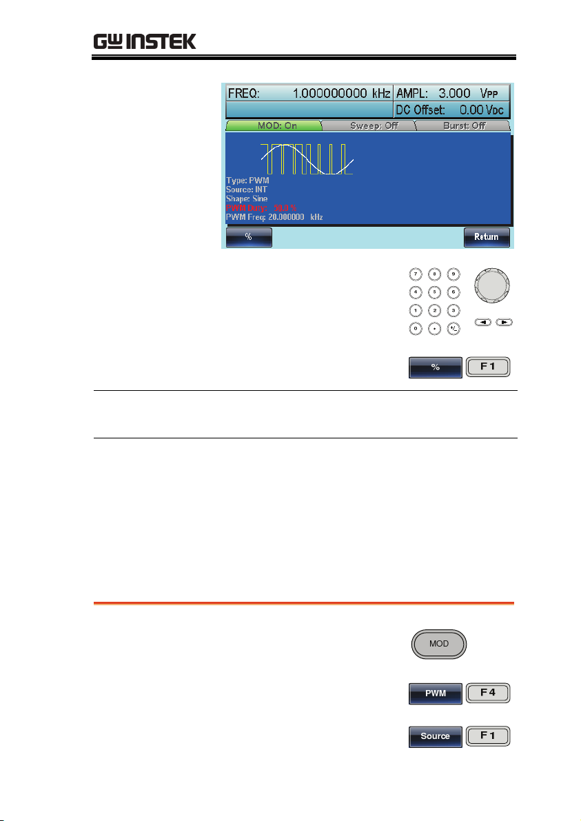
PWM Modulation
Example: PWM modulation. 800Hz Carrier wave. 15 kHz
modulating sine wave. 50% Duty Cycle. Internal Source.
Output
1. Press Waveform
and select Square
(F2).
2. Press the MOD key
and select PWM
(F4).
Input: N/A
3. Press the Freq/Rate
key, followed by 8 +
0 + 0 + Hz (F4).
4. Press the MOD key,
select PWM (F4),
Shape (F4), Sine
(F1).
5. Press the MOD key,
PWM (F4), PWM
Freq (F3).
31
Page 32

AFG-3000 Series User Manual
6. Press 1 + 5 + kHz
(F3).
7. Press MOD, PWM
(F4), Duty (F2).
8. Press 5 + 0 + % (F1).
9. Press MOD, PWM
(F4), Source (F1),
INT (F1).
10. Press the output
key.
Sweep
Example: Frequency Sweep. Start Frequency 10mHz, Stop frequency
1MHz. Log sweep, 1 second sweep, Marker Frequency 550 Hz,
Manual Trigger, Trigger out, rising edge.
Output
1. Press Sweep, Start
(F3).
2. Press 1 + 0 + mHz
Input: N/A
32
(F2).
3. Press Sweep, Stop
(F4).
4. Press 1 + MHz (F5).
5. Press Sweep, Type
(F2), Log (F2).
Page 33

QUICK REFERENCE
6. Press Sweep, SWP
Time (F5).
7. Press 1 + SEC (F2).
8. Press Sweep, More
(F6), Marker (F3),
ON/OFF (F2), Freq
(F1).
9. Press 5 + 5 + 0 + Hz
(F3)
10. Press Sweep, More
(F6), TRIG out (F4),
ON/OFF (F3), Rise
(F1).
11. Press the output
key.
12. Press Sweep, Source
(F1), Manual (F3),
Trigger (F1).
Burst
Example: Burst Mode, N-Cycle (Internally triggered), 1kHz burst
frequency, Burst count = 5, 10 ms Burst period, 0˚ burst phase,
Internal trigger, 10 us delay, rising edge trigger out
Output
1. Press FREQ/Rate 1
kHz (F5).
2. Press Burst, N Cycle
(F1), Cycles (F1).
33
Page 34

AFG-3000 Series User Manual
Input: N/A
3. Press 5 + Cyc (F5).
4. Press Burst, N Cycle
(F1), Period (F4).
5. Press 1 +0 + msec
(F2).
6. Press Burst, N Cycle
(F1), Phase (F3).
7. Press 0 + Degree
(F5).
8. Press Burst, N Cycle
(F1), TRIG Setup
(F5), INT (F1).
9. Press Burst, N Cycle
(F1), TRIG Setup
(F5), Delay (F4).
10. Press 1 + 0 + uSEC
(F2).
11. Press Burst, N Cycle
(F1), TRIG Setup
(F5), TRIG out (F5),
ON/OFF (F3), Rise
(F1).
34
12. Press the output
key.
Page 35

QUICK REFERENCE
ARB
ARB – Add Built-In Waveform
Example: ARB Mode, Exponential Rise. Start 0, Length 100, Scale
32767.
Output
1. Press ARB, Built in
(F3), More (F5), Exp
Rise (F1).
2. Press Start (F1), 0 +
Enter (F5), Return
(F6).
3. Press Length (F2),
100, Enter (F5),
Return (F6).
4. Press Scale (F3),
32767, Enter (F5),
Return (F6), Done
(F4).
ARB – Add Built-In Waveform - Pulse
Example: ARB Mode, Pulse. Start 0, Frequency 1kHz, Duty 25%.
Output
5. Press ARB, Built in
(F3), More (F5), Exp
Rise (F1).
6. Press Freq.(F1),1,
kHz (F5), Return
(F6).
35
Page 36

AFG-3000 Series User Manual
7. Press Duty (F2), 25,
%(F5), Return (F6).
8. Press Scale (F3),
32767, Enter (F5),
Return (F6), Done
(F4).
ARB - Add Point
Example: ARB Mode, Add point, Address 40, data 30,000.
Output
1. Press ARB, Edit
(F2), Point (F1),
Address (F1).
2. Press 4 + 0 + Enter
(F5), Return (F6).
3. Press Data (F2),
3+0+0+0+0, Enter
(F5).
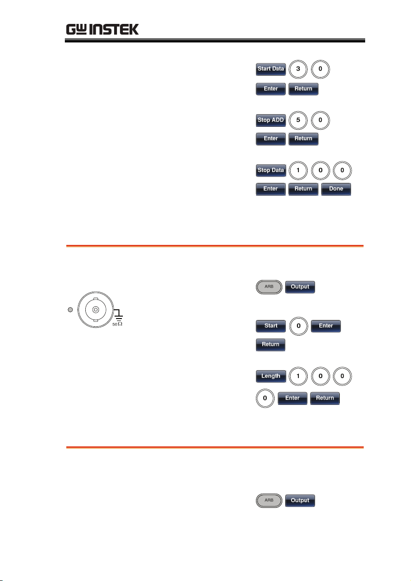
ARB - Add Line
Example: ARB Mode, Add line, Address:Data (10:30, 50:100)
Output
1. Press ARB, Edit
(F2), Line (F2), Start
ADD (F1).
2. Press 1 + 0 + Enter
(F5), Return (F6).
36
Page 37
QUICK REFERENCE
3. Press Start Data
(F2), 3 + 0, Enter
(F5), Return (F6).
4. Press Stop ADD
(F3), 5 + 0, Enter
(F5), Return (F6).
5. Press Stop Data (F4),
1 + 0 + 0, Enter (F5),
Return (F6), Done
(F5).
ARB – Output Section
Example: ARB Mode, Output ARB Waveform, Start 0, Length 1000.
Output
1. Press ARB, Output
(F6).
2. Press Start (F1), 0 +
Enter (F5), Return
(F6).
3. Press Length (F2), 1
+ 0 + 0, Enter (F5),
Return (F6).
ARB – Output N Cycle
Example: ARB Mode, Output N Cycle, Start 0, Length 1000, N Cycle
10.
Output
1. Press ARB, Output
(F6).
37
Page 38
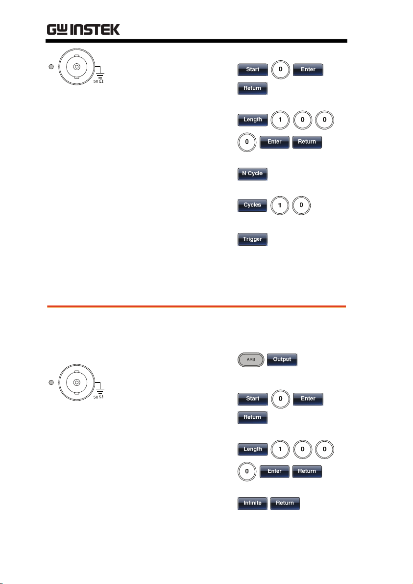
AFG-3000 Series User Manual
2. Press Start (F1), 0 +
Enter (F5), Return
(F6).
3. Press Length (F2), 1
+ 0 + 0, Enter (F5),
Return (F6).
4. Press N Cycle (F4).
5. Press Cycles (F1), 1
+ 0.
6. To trigger the
output once, press
Trigger (F5).
ARB – Output Infinite Cycles
Example: ARB Mode, Output N Cycle, Start 0, Length 1000, Cycles
Infinite.
Output
1. Press ARB, Output
(F6).
2. Press Start (F1), 0 +
Enter (F5), Return
(F6).
3. Press Length (F2), 1
+ 0 + 0, Enter (F5),
Return (F6).
38
4. Press Infinite (F5),
Return (F6).
Page 39

QUICK REFERENCE
ARB – Output Markers
Example: ARB Mode, Output Markers, Start 0, Length 80.
Output
1. Press ARB, Output
(F6), Marker (F3).
2. Press Start (F1), 3+0,
Enter (F5), Return
(F6).
3. Press Length (F2), 8
+ 0, Enter (F5),
Return (F6).
Utility Menu
Save
Example: Save to Memory file #5.
1. Press UTIL,
Memory (F1), Store
(F1).
2. Choose a file using
the scroll wheel and
Select (F1), press
Done (F5).
39
Page 40

AFG-3000 Series User Manual
Recall
Example: Recall Memory file #5.
1. Press UTIL,
Memory (F1), Recall
(F2).
2. Choose a file using
the scroll wheel and
Select (F1), press
Done (F5).
Interface GPIB
Example: GPIB interface, Address 10.
GPIB
1. Press UTIL,
Interface (F2), GPIB
(F1), Address (F1).
2. Press 1 + 0 + Done
(F5).
40
Page 41

QUICK REFERENCE
Interface RS232
Example: RS232 interface, Baud 115200, Parity None, Bits 8.
RS232
1. Press UTIL,
Interface (F2), RS232
(F2).
2. Press Baud Rate
(F1), 115k (F5).
3. Press UTIL,
Interface (F2), RS232
(F2).
4. Press Parity/Bits
(F2), None/8Bits
(F1).
Interface USB
Example: USB interface.
1. Press UTIL,
USB B
Interface (F2), USB
(F3).
41
Page 42

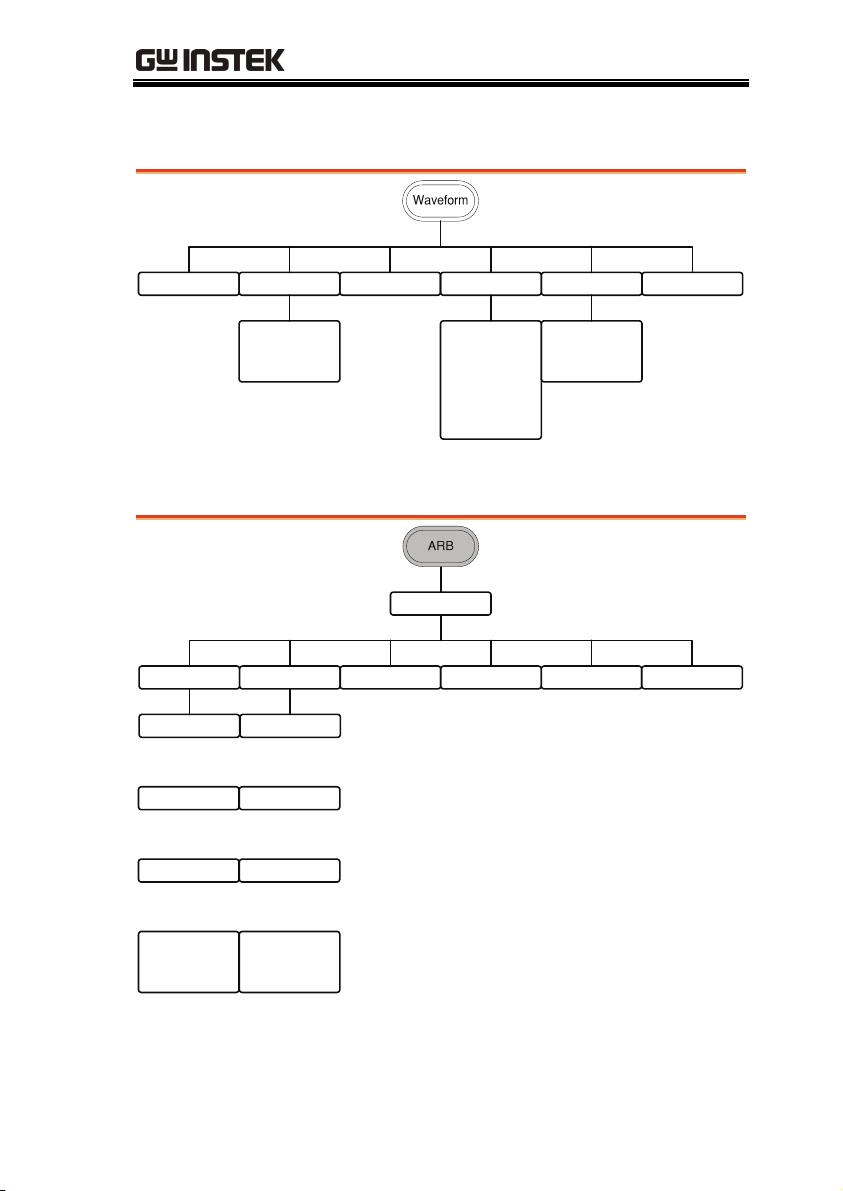
Menu Tree
AFG-3000 Series User Manual
Convention
Use the menu trees as a handy reference for the
function generator functions and properties. The AFG3000 menu system is arranged in a hierarchical tree.
Each hierarchical level can be navigated with the
operation or soft menu keys. Pressing the Return soft
key will return you to the previous menu level.
For example: To set the parity to Even/7Bits;
(1)Press the UTIL key.
(2)The Interface softkey.
(3) RS232.
(4) Parity/Bits
(5) Even/7Bits.
3
Baud Rate
9600
19.2K
38.4K
57.6K
115K
Return
4
Parity/Bits
None/8Bits
Odd/7Bits
5
Even/7Bits
Return
Return
1
2
Interface
Level 1
Level 2
Level 3
Level 4
Level 5
GPIB RS-232 USB Return
Address
Clear
Done
Return
Return
42
Page 43
QUICK REFERENCE
Waveform
Sine Square Triangle Pulse Ramp Noise
Duty
%
Return
Width
nSEC
uSEC
SYM
%
Return
mSEC
SEC
Return
ARB-Display
Display
Horizon Vertical Next Page Back Page Overview Return
Start
Clear
Enter
Return
Length
Clear
Enter
Return
Center
Clear
Enter
Return
Zoom in
Zoom out
Return
Low
Clear
Enter
Return
High
Clear
Enter
Return
Center
Clear
Enter
Return
Zoom in
Zoom out
Return
43
Page 44

AFG-3000 Series User Manual
ARB-Edit
Edit
Point Line Copy Clear Protect Return
Address
Clear
Enter
Return
Data
Clear
Enter
Return
Return
Start ADD
Clear
Enter
Return
Start Data
Clear
Enter
Return
Stop ADD
Clear
Enter
Return
Stop Data
Clear
Enter
Return
Done
Return
Start
Clear
Enter
Return
Length
Clear
Enter
Return
Paste To
Clear
Enter
Return
Done
Return
Start
Clear
Enter
Return
Length
Clear
Enter
Return
Done
All
Done
Return
Return
All
Done
Start
Clear
Enter
Return
Length
Clear
Enter
Return
Done
Unprotect
Done
Return
44
Page 45

QUICK REFERENCE
ARB-Built in
Built in
Sine Square Ramp Sinc More Return
Start
Clear
Enter
Return
Length
Clear
Enter
Return
Scale
Clear
Enter
Return
Done
Return
Start
Clear
Enter
Return
Length
Clear
Enter
Return
Scale
Clear
Enter
Return
Done
Return
Start
Clear
Enter
Return
Length
Clear
Enter
Return
Scale
Clear
Enter
Return
Done
Return
Start
Clear
Enter
Return
Length
Clear
Enter
Return
Scale
Clear
Enter
Return
Done
Return
Go to ARB
Built in -
More
45
Page 46

AFG-3000 Series User Manual
ARB- Built in- More
Built in
More
Exp Rise Exp Fall DC Pulse
Start
Clear
Enter
Return
Length
Clear
Enter
Return
Scale
Clear
Enter
Return
Done
Return
Start
Clear
Enter
Return
Length
Clear
Enter
Return
Scale
Clear
Enter
Return
Done
Return
Start
Clear
Enter
Return
Length
Clear
Enter
Return
Data
Clear
Enter
Return
Done
Return
Freq
nHz
uHz
mHz
Hz
kHz
Return
Duty
%
Return
Done
Return
Return
46
Page 47

ARB-Save
ARB-Load
QUICK REFERENCE
47
Page 48

ARB-Output
AFG-3000 Series User Manual
Output
Start Length Marker N Cycle
Clear
Enter
Return
Clear
Enter
Return
Start
Clear
Enter
Return
Length
Clear
Enter
Return
Return
Cycles
Clear
Enter
Return
Trigger
Return
Infinite Return
48
Page 49

QUICK REFERENCE
MOD
AM FM FSK PWM
Source
Int
EXT
Return
Depth
%
Return
AM Freq
mHz
Hz
kHz
Return
Shape
Sine
Square
Triangle
UpRamp
DnRamp
Return
Return
Sweep
Source
Int
EXT
Return
Freq Dev
uHz
mHz
Hz
kHz
MHz
Return
FM Freq
mHz
Hz
kHz
Return
Shape
Sine
Square
Triangle
UpRamp
DnRamp
Return
Return
Source
Int
EXT
Return
Hop Freq
uHz
mHz
Hz
kHz
MHz
Return
FSK Rate
mHz
Hz
kHz
MHz
Return
Return
Source
Int
EXT
Return
Duty
%
Return
PWM Freq
mHz
Hz
kHz
Return
Shape
Sine
Square
Triangle
UpRamp
DnRamp
Return
Return
Source Type Start Stop SWP Time More
Int
EXT
Manual
Trigger
Return
Return
Linear
Log
Return
uHz
mHz
Hz
kHz
MHz
Return
uHz
mHz
Hz
kHz
MHz
Return
mSEC
SEC
Return
Go to the
Sweep -
More menu
49
Page 50

Sweep - More
AFG-3000 Series User Manual
50
Page 51

Burst – N Cycle
QUICK REFERENCE
N Cycle
Cycles Infinite Phase Period
Clear
Cyc
Return
Clear
Degree
Return
Burst - Gate
Gate
uSEC
mSEC
SEC
Return
TRIG Setup Return
Int
EXT
Rise
Fall
Return
Manual
Trigger
Return
Delay
nSEC
uSEC
mSEC
SEC
Return
TRIG out
Rise
Fall
ON/OFF
Return
Return
Polarity Phase Return
Pos
Neg
Return
Clear
Degree
Return
51
Page 52

AFG-3000 Series User Manual
UTIL
Memory Interface Cal. Load System DSO-Link
Store
Select
Done
Return
Recall
Select
Done
Return
Go to the
UTIL –
Interface
menu
Self Test
Software
Version
Upgrade
Return
Return
Delete
Select
Done
Return
Delete All
Done
Return
Return
UTIL - Interface
Interface
GPIB RS-232 USB Return
Address
Clear
Done
Return
Return
Baud Rate
9600
19.2K
38.4K
57.6K
115K
Return
Parity/Bits
None/8Bits
Odd/7Bits
Even/7Bits
Return
Return
50 OHM
High Z
Return
Hardcopy
Language
中文
English
Return
Help
Select
Return
Beep
Return
Search
CH1
CH2
CH3
CH4
Return
52
Page 53

QUICK REFERENCE
Default Settings
Here are the default panel settings which appear
when pressing the Preset key.
Output Config.
Function Sine wave
Modulation
(AM/FM/FSK)
Sweep
Frequency 1kHz
Amplitude 3.000 Vpp
Offset 0.00V dc
Output units Vpp
Output terminal 50Ω
Carrier Wave 1kHz Sine wave
Modulation waveforms 100Hz Sine wave
AM Depth 100%
FM Deviation 100Hz
FSK Hop Frequency 100Hz
FSK Frequency 10Hz
PWM Duty 50%
PWM Frequency 20kHz
Modem Status Off
Start/Stop frequency 100Hz/1kHz
Sweep time 1s
Sweep type Linear
Sweep status Off
53
Page 54

AFG-3000 Series User Manual
Burst
System settings
Trigger
Interface config.
Burst Frequency 1kHz
Ncycle 1
Burst period 10ms
Burst starting phase 0˚
Burst status Off
Power off signal On
Display mode On
Error queue cleared
Memory settings No change
Output Off
Trigger source Internal (immediate)
GPIB Address 10
Interface RS232
Baud rate 115200
Calibration
54
Parity None (8 data bits)
Calibration Menu Restricted
Page 55

OPERATION
OPERATION
The Operation chapter shows how to output basic waveform
functions. For details on modulation, sweep, burst and arbitrary
waveforms, please see the Modulation and Arbitrary waveform
chapters on pages 65 and 137.
Select a Waveform ............................................................. 56
Sine Wave ............................................................................. 56
Setting a Square Wave ......................................................... 57
Triangle Wave ....................................................................... 58
Setting the Pulse Width ........................................................ 59
Setting a Ramp ..................................................................... 60
Noise Wave .......................................................................... 61
Setting the Frequency ........................................................... 61
Setting the Amplitude .......................................................... 63
Setting the DC Offset ........................................................... 64
55
Page 56

AFG-3000 Series User Manual
Select a Waveform
The AFG-3000 can output six standard waveforms: sine, square,
triangle, pulse, ramp and noise waveforms.
Sine Wave
Panel Operation
1. Press the Waveform key.
2. Press F1 (Sine).
56
Page 57
OPERATION
Setting a Square Wave
Panel Operation
1. Press the Waveform key.
2. Press F2 (Square) to create a
square waveform.
3. Press F1 (Duty). The Duty
parameter will be
highlighted in the
parameter window.
4. Use the selector keys and
scroll wheel or number pad
to enter the Duty range.
5. Press F5 (%) to choose %
units.
Range Frequency Duty Range
≤25MHz
25MHz~≤50MHz
20%~80%
40%~60%
>50MHz~80MHz 50% (Fixed)
57
Page 58
Triangle Wave
AFG-3000 Series User Manual
Panel Operation
1. Press the Waveform key.
2. Press F3 (Triangle).
58
Page 59

OPERATION
Setting the Pulse Width
Panel Operation
Range Pulse Width 8ns~1999.9s
Note
1. Press the Waveform key.
2. Press F4 (Pulse) to create a
pulse waveform.
3. Press F1 (Width). The Width
parameter will be
highlighted in the
parameter window.
4. Use the selector keys and
scroll wheel or number pad
to enter the pulse width.
5. Press F2~F5 choose the unit
range.
Minimum Pulse Width
Freq ≤ 50MHz: 8ns pulse
width
Freq ≤ 6.25 MHZ: 5% duty
cycle
~
Resolution
Freq ≤ 50MHz: 1ns pulse
width
Freq ≤ 6.25 MHZ: 1% duty
cycle
59
Page 60

AFG-3000 Series User Manual
Setting a Ramp
Panel Operation
1. Press the Waveform key.
2. Press F5 (Ramp) to create a
ramp waveform.
3. Press F1 (SYM). The SYMM
parameter will be
highlighted in the
parameter window.
4. Use the selector keys and
scroll wheel or number pad
to enter the symmetry
percentage.
5. Press F5 (%) to choose %
/
units.
Range Symmetry 0%~100%
60
Page 61

Noise Wave
OPERATION
Panel Operation
1. Press the Waveform key.
2. Press F6 (Noise).
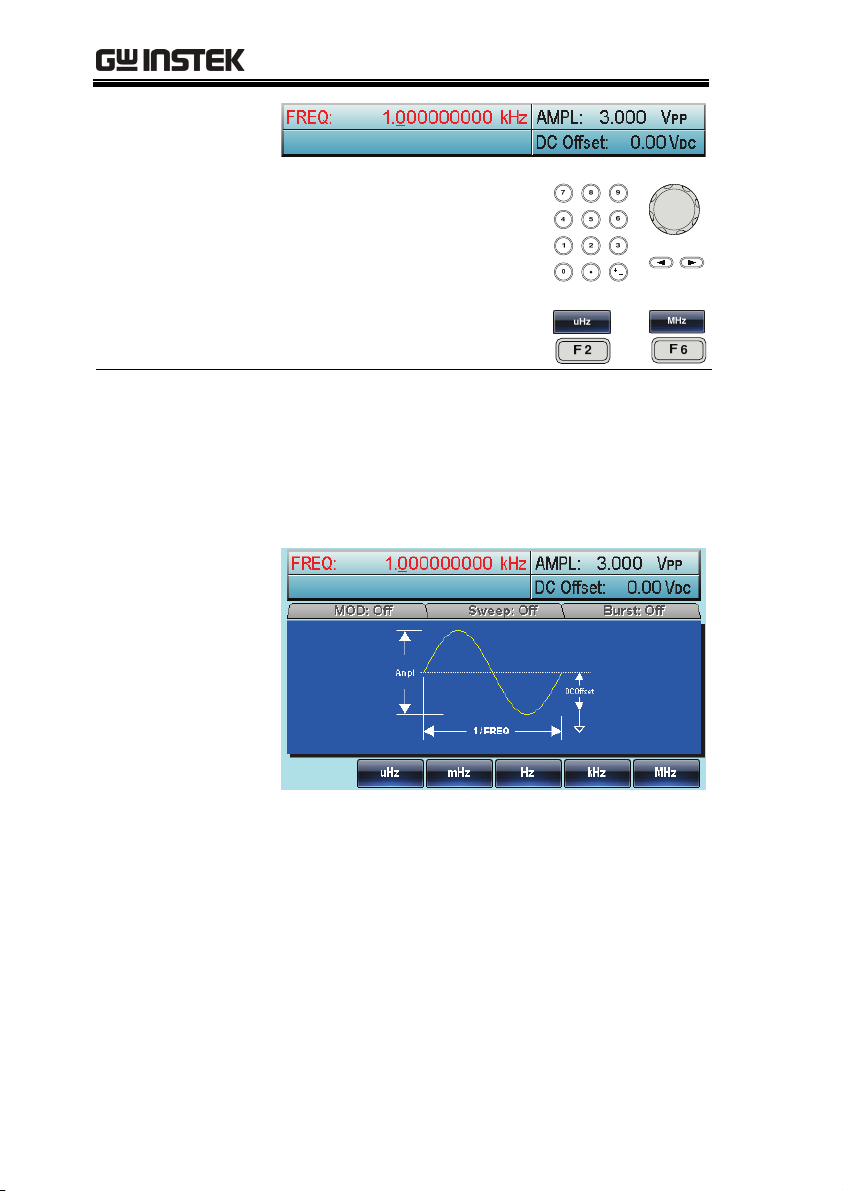
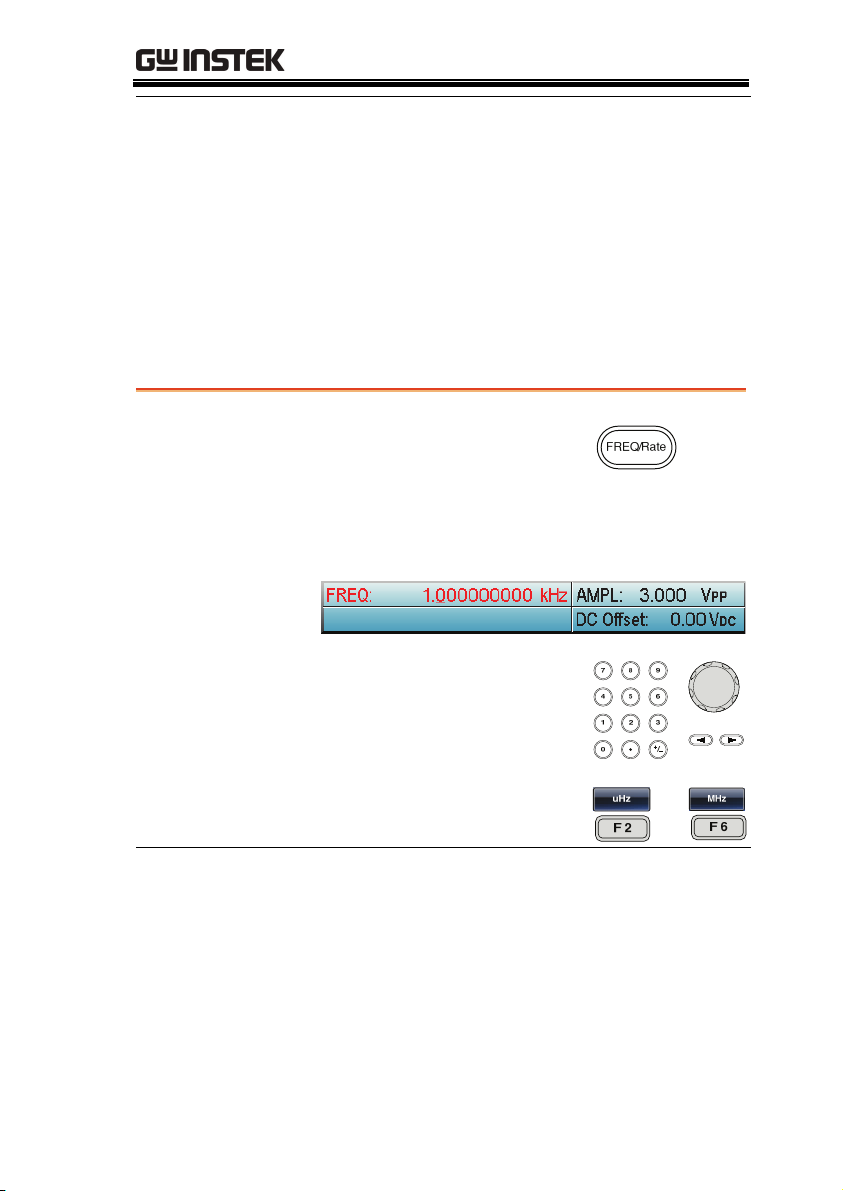
Setting the Frequency
Panel Operation
1. Press the FREQ/Rate key.
2. The FREQ parameter will become highlighted
in the parameter window.
61
Page 62
AFG-3000 Series User Manual
Range Sine
3. Use the selector keys and
scroll wheel or number pad
to enter the frequency.
4. Choose a frequency unit by
pressing F2~F6.
1μHz~80MHz(3081)/50MHz(3051)
Square
Tr ia n gl e
Pulse
Ramp
1μHz~80MHz(3081)/50MHz(3051)
1μHz~1MHz
500μHz~50MHz
1μHz~1MHz
/
~
62
Page 63
OPERATION
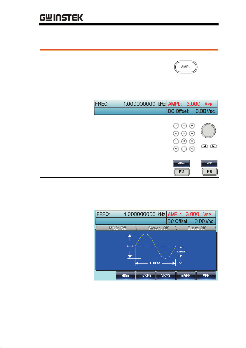
Setting the Amplitude
Panel Operation
1. Press the AMPL key.
2. The AMPL parameter will become
highlighted in the parameter window.
3. Use the selector keys and
scroll wheel or number pad
to enter the amplitude.
4. Choose a unit type by
pressing F2~F6.
50Ω load
Range 10mVpp~10Vpp 20mVpp~20Vpp
Unit Vpp, Vrms, dBm
~
High Z
63
Page 64

AFG-3000 Series User Manual
Setting the DC Offset
Panel Operation
1. Press the DC Offset key.
2. The DC Offset parameter will become
highlighted in the parameter window.
3. Use the selector keys and
scroll wheel or number pad
to enter the DC Offset.
4. Press F5 (mVDC) or F6
(VDC) to choose a voltage
range.
50Ω load
Range ±5Vpk ±10Vpk
/
High Z
64
Page 65

MODULATION
MODULATION
The AFG-3000 Series Arbitrary Function Generators are able to
produce AM, FM, FSK and PWM modulated waveforms. Depending
on the type of waveform produced, different modulation parameters
can be set. Only one modulation mode can be active at any one time.
The function generator also will not allow sweep or burst mode to
be used with AM/FM. Activating a modulation mode will turn the
previous modulation mode off.
Amplitude Modulation (AM) ............................................. 67
Selecting AM Modulation .................................................... 68
AM Carrier Shape ................................................................. 68
Carrier Frequency ................................................................. 69
Modulating Wave Shape ...................................................... 70
AM Frequency ...................................................................... 71
Modulation Depth ................................................................ 72
Selecting (AM) Modulation Source ..................................... 73
Frequency Modulation (FM) .............................................. 75
Selecting Frequency Modulation (FM) ................................ 76
FM Carrier Shape ................................................................. 76
FM Carrier Frequency ........................................................... 77
FM Wave Shape.................................................................... 78
Frequency Modulation Waveform ....................................... 79
Frequency Deviation ............................................................. 80
Selecting (FM) Modulation Source ..................................... 81
Frequency Shift Keying (FSK) Modulation .......................... 83
Selecting FSK Modulation .................................................... 84
FSK Carrier Shape ................................................................ 84
FSK Carrier Frequency .......................................................... 85
FSK Hop Frequency .............................................................. 86
FSK Rate. .............................................................................. 87
FSK Source ........................................................................... 88
Pulse Width Modulation .................................................... 90
Selecting Pulse Width Modulation ...................................... 91
PWM Carrier Shape .............................................................. 91
PWM Carrier Frequency ....................................................... 92
65
Page 66

AFG-3000 Series User Manual
PWM Modulating Wave Shape ............................................ 92
Modulating Waveform Frequency ....................................... 93
Modulation Duty Cycle ........................................................ 94
PWM Source ........................................................................ 95
Frequency Sweep ............................................................... 97
Selecting Sweep Mode ......................................................... 98
Setting Start and Stop Frequency ........................................ 98
Center Frequency and Span ............................................... 100
Sweep Mode ....................................................................... 102
Sweep Time ........................................................................ 103
Marker Frequency .............................................................. 104
Sweep Trigger Source ........................................................ 105
Trigger Output ................................................................... 106
Burst Mode ..................................................................... 108
Selecting Burst Mode ......................................................... 109
Burst Modes ....................................................................... 109
Burst Frequency ................................................................. 110
Burst Cycle/Burst Count .................................................... 111
Infinite Burst Count ........................................................... 112
Burst Period ....................................................................... 113
Burst Phase ........................................................................ 115
Burst Trigger Source .......................................................... 116
Burst Delay ......................................................................... 118
Burst Trigger Output ......................................................... 119
66
Page 67

MODULATION
Amplitude Modulation (AM)
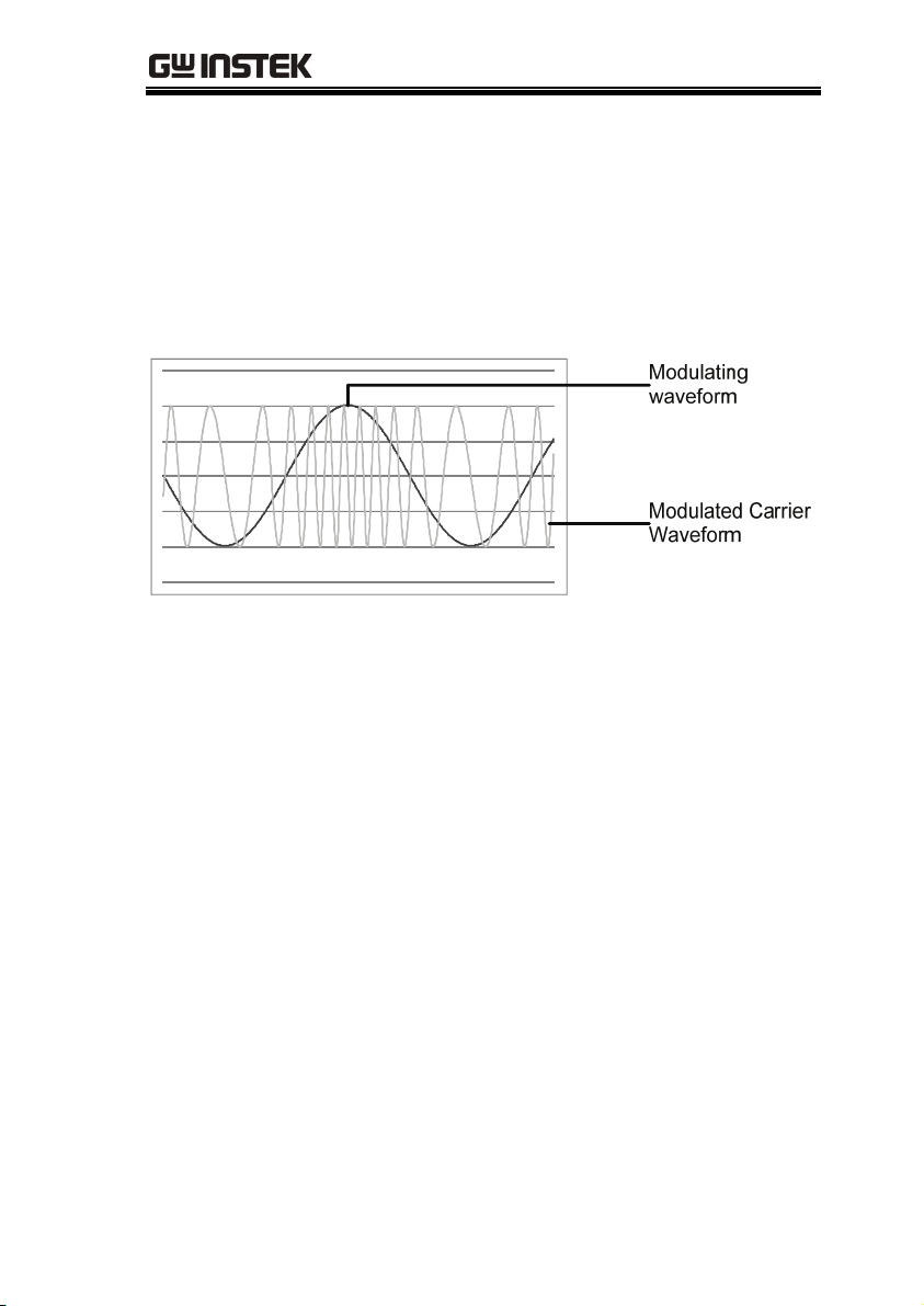
An AM waveform is produced from a carrier waveform and a
modulating waveform. The amplitude of the modulated carrier
waveform depends on the amplitude of the modulating waveform.
The AFG-3000 function generator can set the carrier frequency,
amplitude and offset as well as internal or external modulation
sources.
67
Page 68

AFG-3000 Series User Manual
Selecting AM Modulation
Panel Operation
AM Carrier Shape
Background
The shape function selects the AM carrier
waveform shape. Sine, square, triangle, ramp,
pulse or arbitrary waveforms can be used as the
carrier shape. The default waveform shape is set to
sine. Noise is not available as a carrier shape.
Before the carrier shape can be selected, choose
AM modulation mode, see page 28 or 70.
1. Press the MOD key.
2. Press F1 (AM).
Select a Standard
Carrier Shape
68
1. Press the Waveform key.
2. Press F1~F5 to choose the
carrier wave shape.
~
Page 69

MODULATION
Select an
Arbitrary
Waveform Carrier
Shape.
Range AM Carrier Shape sine, square, triangle, upramp,
3. See the Arbitrary waveform
quick guide or chapter to
use an arbitrary waveform.
dnramp, arbitrary waveform
Page 35
Page 137
Carrier Frequency
The maximum carrier frequency depends on the carrier shape
selected. The default carrier frequency for all carrier shapes is 1kHz.
Panel Operation
1. With a carrier waveform,
press the FREQ/Rate key.
2. The FREQ parameter will become highlighted
in the parameter window.
3. Use the selector keys and
scroll wheel or number pad
to enter the carrier
frequency.
Range Carrier Shape Carrier Frequency
4. Press F2~F6 to select the
frequency range.
Sine
Square
Tr ia n gl e
Pulse
Ramp
1μHz~80MHz(3081)/
50MHz(3051)
1μHz~80MHz(3081)/
50MHz(3051)
1μHz~1MHz
500μHz~50MHz
1μHz~1MHz
~
69
Page 70

AFG-3000 Series User Manual
Modulating Wave Shape
The function generator can accept internal as well as external
sources. The AFG-3000 has sine, square, triangle, up ramp and down
ramp modulating waveform shapes. Sine waves are the default
wave shape.
Panel Operation
Note Square wave 50% Duty cycle
1. Select MOD.
2. Press F1 (AM).
3. Press F4 (Shape).
4. Press F1~F5 to select the
waveform shape.
5. Press F6 (Return) to return
to the menu.
UpRamp 100% Symmetry
Triangle 50% Symmetry
DnRamp 0% Symmetry
~
70
Page 71

MODULATION
AM Frequency
The frequency of the modulation waveform (AM Frequency) can be
set from 2mHz to 20kHz.
Panel Operation
1. Press the MOD key.
2. Press F1 (AM).
3. Press F3 (AM Freq).
4. The AM Freq parameter will become
highlighted in the Waveform display area.
5. Use the selector keys and
scroll wheel or number pad
to enter the AM frequency.
Range Modulation frequency 2mHz~20kHz
Default frequency 100Hz
6. Press F1~F3 to select the
frequency range.
~
71
Page 72

AFG-3000 Series User Manual
Modulation Depth
Modulation depth is the ratio (as a percentage) of the unmodulated
carrier amplitude and the minimum amplitude deviation of the
modulated waveform. In other words, modulation depth is the
maximum amplitude of the modulated waveform compared to the
carrier waveform as a percentage.
Panel Operation
1. Press the MOD key.
2. Press F1 (AM).
3. Press F2 (Depth).
4. The AM Depth parameter will become
highlighted in the waveform display area.
5. Use the selector keys and
scroll wheel or number pad
to enter the AM depth.
/
72
Page 73

MODULATION
~
6. Press F1 (%) to choose %
units.
Range Depth 0%~120%
Default depth 100%
Note
When the modulation depth is greater than 100%, the
output cannot exceed ±5VPeak (10kΩ load).
If an external modulation source is selected,
modulation depth is limited to ± 5V from the MOD
INPUT terminal on the rear panel. For example, if
modulation depth is set to 100%, then the maximum
amplitude is +5V, and the minimum amplitude is -5V.
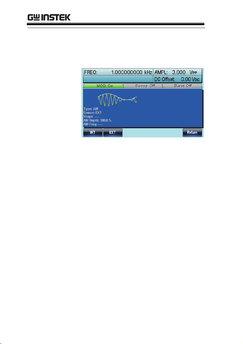
Selecting (AM) Modulation Source
The function generator will accept an internal or external source for
AM modulation. The default source is internal.
Panel Operation
1. Press the MOD key.
2. Press F1 (AM).
3. Press F1 (Source).
4. To select the source, press
F1 (Internal) or F2
(External).
External Source
5. Press F6 (Return) to return
to the menu.
Use the MOD INPUT terminal
on the rear panel when using an
external source.
73
Page 74
AFG-3000 Series User Manual
Note If an external modulation source is selected,
modulation depth is limited to ± 5V from the MOD
INPUT terminal on the rear panel. For example, if
modulation depth is set to 100%, then the maximum
amplitude is +5V, and the minimum amplitude is -5V.
74
Page 75
MODULATION
Frequency Modulation (FM)
A FM waveform is produced from a carrier waveform and a
modulating waveform. The instantaneous frequency of the carrier
waveform varies with the magnitude of the modulating waveform.
When using the AFG-3000 function generator, only one type of
modulated waveform can be created at any one time.
75
Page 76

AFG-3000 Series User Manual
Selecting Frequency Modulation (FM)
When FM is selected, the modulated waveform depends on the
carrier frequency, the output amplitude and offset voltage.
Panel Operation
FM Carrier Shape
Background
The Shape mode selects the FM carrier waveform
shape. The default waveform shape is set to sine.
Noise and Pulse waveforms cannot be used as a
carrier wave.
1. Press the MOD key.
2. Press F2 (FM).
Panel Operation
76
1. Press the Waveform key.
2. Press F1~F5 to choose the
carrier wave shape. (bar F4)
~
Page 77
MODULATION
Range Carrier Shape Sine, Square, Triangle,
Ramp.
FM Carrier Frequency
When using the AFG-3000 function generator, the carrier frequency
must be equal to or greater than the frequency deviation. If the
frequency deviation is set to value greater than the carrier frequency,
the deviation is set to the maximum allowed. The maximum
frequency of the carrier wave depends on the waveform shape
chosen.
Panel Operation
Range Carrier Shape Carrier Frequency
1. To select the carrier
frequency, press the FREQ/
Rate key.
2. The FREQ parameter will become highlighted
in the parameter window.
3. Use the selector keys and
scroll wheel or number pad
to enter the carrier
frequency.
4. Press F2~F6 to select the
frequency unit.
Sine
Square
Tr ia n gl e
Ramp
Default frequency 1 kHz
1μHz~80MHz(3081)/
50MHz(3051)
1μHz~80MHz(3081)/
50MHz(3051)
1μHz~1MHz
1μHz~1MHz
~
77
Page 78
AFG-3000 Series User Manual
FM Wave Shape
The function generator can accept internal as well as external
sources. The AFG-3000 has sine, square, triangle, positive and
negative ramps (UpRamp, DnRamp) as the internal modulating
waveform shapes. Sine is the default wave shape.
Panel Operation
Note Square wave 50% Duty cycle
1. Select MOD.
2. Press F2 (FM).
3. Press F4 (Shape).
4. Press F1~F5 to select the
waveform shape.
5. Press F6 (Return) to return
to the menu.
UpRamp 100% Symmetry
Triangle 50% Symmetry
DnRamp 0% Symmetry
~
78
Page 79
MODULATION
~
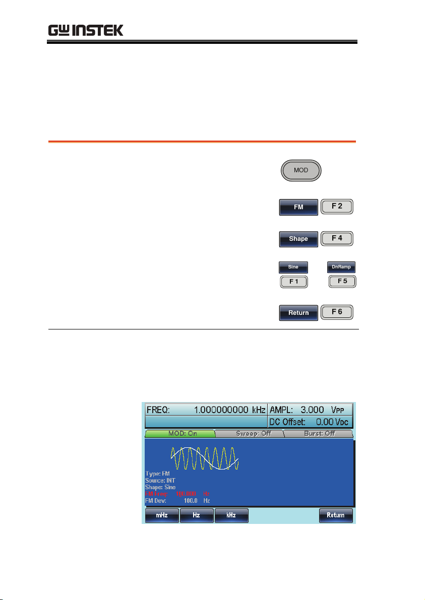
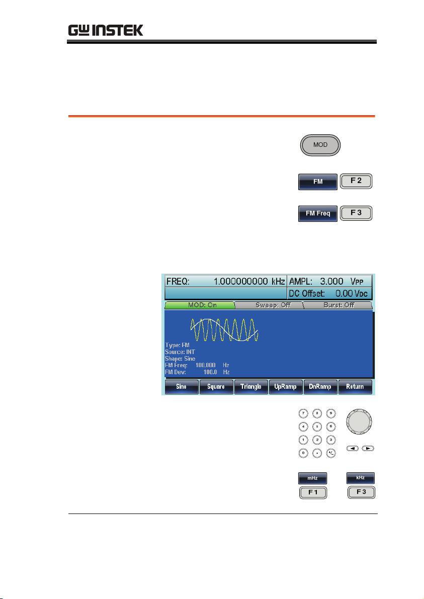
Frequency Modulation Waveform
For frequency modulation, the function generator will accept
internal or external sources.
Panel Operation
1. Press the MOD key.
2. Press F2 (FM).
3. Press F3 (FM Freq).
4. The FM Freq parameter will become
highlighted in waveform display panel.
5. Use the selector keys and
scroll wheel or number pad
to enter the FM frequency.
6. Press F1~F3 to select the
frequency unit.
Range Modulation frequency 2mHz~20kHz
Default frequency 100Hz
79
Page 80

AFG-3000 Series User Manual
Frequency Deviation
The frequency deviation is the peak frequency deviation from the
carrier wave and the modulated wave.
Panel Operation
1. Press the MOD key.
2. Press F2 (FM).
3. Press F2 (Freq Dev).
4. The Freq Dev parameter will become
highlighted in the waveform display panel.
5. Use the selector keys and
scroll wheel or number pad
to enter the frequency
deviation.
/
80
6. Press F1~ F5 to choose the
frequency units.
~
Page 81

MODULATION
~
Range Frequency Deviation DC~80MHz (3081)
DC~50MHz (3051)
DC~1MHz (Triangle)
Default depth 100kHz
Selecting (FM) Modulation Source
The function generator will accept an internal or external source for
FM modulation. The default source is internal.
Panel Operation
External Source
1. Press the MOD key.
2. Press F2 (FM).
3. Press F1 (Source).
4. To select the source, press
F1 (Internal) or F2
(External).
5. Press F6 (Return) to return
to the menu.
Use the MOD INPUT terminal
on the rear panel when using an
external source.
81
Page 82

AFG-3000 Series User Manual
Note
If an external modulating source is selected, the
frequency deviation is limited to the ± 5V MOD
INPUT terminal on the rear panel. The frequency
deviation is proportional to the signal level of the
modulation in voltage. For example, if the
modulation in voltage is +5V, then the frequency
deviation would be equal to the set frequency
deviation. Lower signal levels reduce the
frequency deviation while negative voltage levels
produce frequency deviations with frequencies
below the carrier waveform.
82
Page 83

MODULATION
Frequency Shift Keying (FSK) Modulation
Frequency Shift Keying Modulation is used to shift the frequency
output of the function generator between two preset frequencies
(carrier frequency, hop frequency). The frequency at which the
carrier and hop frequency shift is determined by the internal rate
generator or the voltage level from the Trigger INPUT terminal on
the rear panel.
Only one modulation mode can be used at once. When FSK
modulation is enabled, any other modulation modes will be
disabled. Sweep and Burst also cannot be used with FSK modulation.
Enabling FSK will disable Sweep or Burst mode.
83
Page 84
AFG-3000 Series User Manual
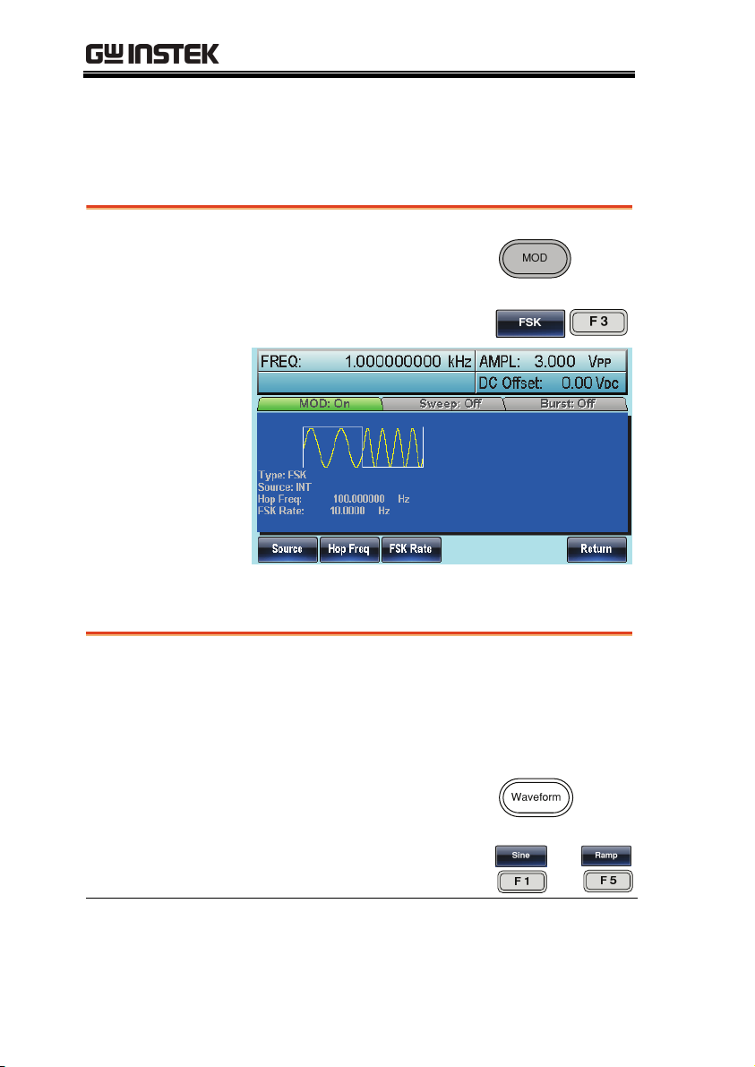
Selecting FSK Modulation
When using FSK mode, the output waveform uses the default
settings for carrier frequency, amplitude and offset voltage.
Panel Operation
1. Press the MOD key.
2. Press F3 (FSK).
FSK Carrier Shape
Background
The shape function selects the FSK carrier
waveform shape. The default waveform shape is
set to sine. Noise waveforms cannot be used as
carrier waves.
Panel Operation
Range Carrier Shape Sine, Square, Triangle,
84
1. Press the Waveform key.
2. Press F1~F5 to choose the
carrier wave shape. (bar F4)
Ramp, Pulse
~
Page 85

MODULATION
FSK Carrier Frequency
The maximum carrier frequency depends on the carrier shape. The
default carrier frequency for all carrier shapes is 1kHz. The voltage
level of the Trigger INPUT signal controls the output frequency
when EXT is selected. When the Trigger INPUT signal is logically
low the carrier frequency is output and when the signal is logically
high, the hop frequency is output.
Panel Operation
Range Carrier Shape Carrier Frequency
1. To select the carrier
frequency, press the FREQ/
Rate key.
2. The FREQ parameter will become highlighted
in the parameter window.
3. Use the selector keys and
scroll wheel or number pad
to enter the carrier
frequency.
4. Press F2~F6 to select the
FSK frequency units.
Sine
Square
Tr ia n gl e
Ramp
1μHz~80MHz(3081)/
50MHz(3051)
1μHz~80MHz(3081)/
50MHz(3051)
1μHz~1MHz
1μHz~1MHz
~
Pulse
500μHz~50MHz
85
Page 86

AFG-3000 Series User Manual
FSK Hop Frequency
The default Hop frequency for all waveform shapes is 100 Hz. A
square wave with a duty cycle of 50% is used for the internal
modulation waveform. The voltage level of the Trigger INPUT
signal controls the output frequency when EXT is selected. When the
Trigger INPUT signal is logically low the carrier frequency is output
and when the signal is logically high, the hop frequency is output.
Panel Operation
1. Press the MOD key.
2. Press F3 (FSK).
3. Press F2 (Hop Freq).
4. The Hop Freq parameter will become
highlighted in the Waveform Display area.
5. Use the selector keys and
scroll wheel or number pad
to enter the hop frequency.
/
86
Page 87

MODULATION
~
6. Press F1~F5 to select the
frequency range.
Range Waveform Carrier Frequency
Sine
1μHz~80MHz(3081)/
50MHz(3051)
Square
1μHz~80MHz(3081)/
50MHz(3051)
Tr ia n gl e
Ramp
Pulse
1μHz~1MHz
1μHz~1MHz
500μHz~50MHz
FSK Rate.
FSK Rate function is used to determine rate at which the output
frequency changes between the carrier and hop frequencies. The
FSK Rate function only applies to internal FSK sources.
Panel Operation
1. Select MOD.
2. Press F3 (FSK).
3. Press F3 (FSK Rate).
4. The FSK Rate parameter will become
highlighted in the waveform display area.
87
Page 88

AFG-3000 Series User Manual
Range FSK Rate 2mHz~100kHz
Note If an external source is selected, FSK Rate settings are
5. Use the selector keys and
scroll wheel or number pad
to enter the FSK rate.
6. Press F1~F5 to select the
frequency unit.
Default 10Hz
ignored.
/
~
FSK Source
The AFG-3000 accepts internal and external FSK sources, with
internal as the default source. When the FSK source is set to internal,
the FSK rate is configured using the FSK Rate function. When an
external source is selected the FSK rate is equal to the frequency of
the Trigger INPUT signal on the rear panel.
Panel Operation
1. Press the MOD key.
88
2. Press F3 (FSK).
Page 89

MODULATION
~
Note Note that the Trigger INPUT terminal cannot
3. Press F1 (Source).
4. To select the source, press
F1 (Internal) or F2
(External).
5. Press F6 (Return) to return
to the menu.
configure edge polarity.
89
Page 90
AFG-3000 Series User Manual
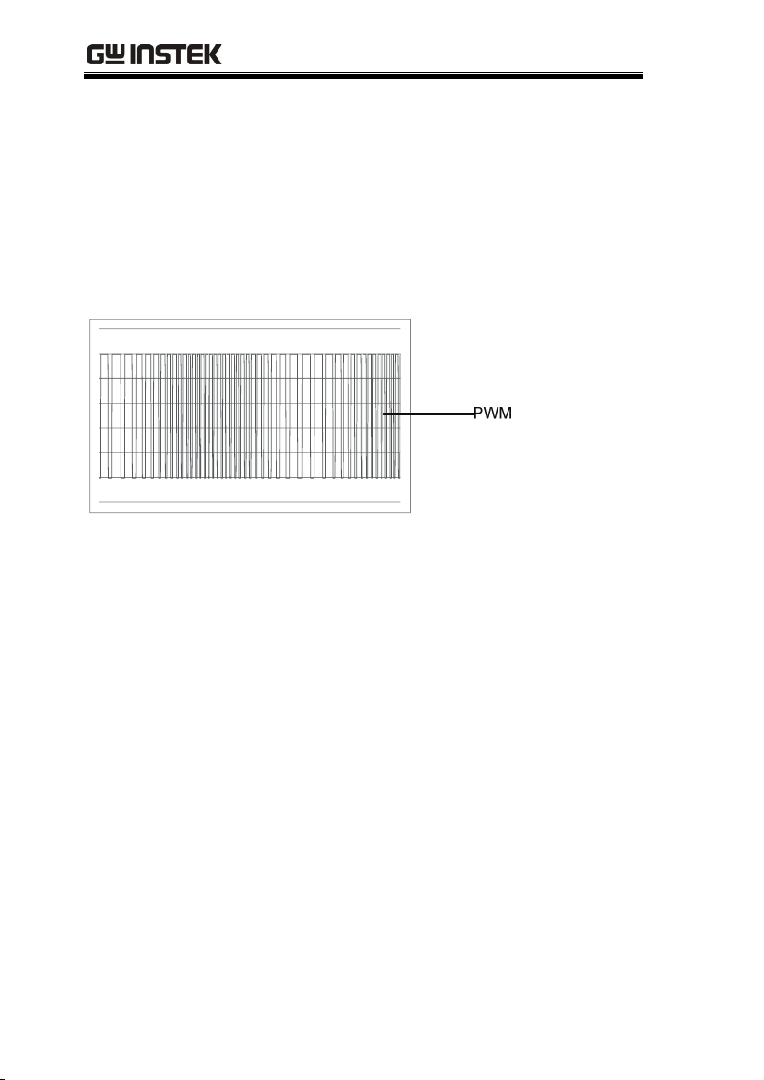
Pulse Width Modulation
For pulse width modulation the instantaneous voltage of the
modulating waveform determines the width of the pulse waveform.
Only one mode of modulation can be enabled at any one time. If
PWM is enabled, any other modulation mode will be disabled.
Likewise, burst and sweep modes cannot be used with PWM and
will be disabled when PWM is enabled.
90
Page 91

MODULATION
Selecting Pulse Width Modulation
When selecting PWM, the current setting of the carrier frequency,
the amplitude modulation frequency, output, and offset voltage
must be considered.
Panel Operation
1. Press the MOD key.
2. Press F2 (Square).
3. Press the MOD key.
4. Press F4 (PWM).
PWM Carrier Shape
PWM uses a square wave as the carrier shape. Other wave shapes
cannot be used with PWM. If a carrier shape other than square is
used with PWM, an error message will appear.
91
Page 92

AFG-3000 Series User Manual
PWM Carrier Frequency
The carrier frequency depends on the square wave. The default
carrier frequency is 1kHz.
Panel Operation
1. To select the carrier
frequency, press the FREQ/
Rate key.
2. The FREQ parameter will become highlighted
in the parameter window.
3. Use the selector keys and
scroll wheel or number pad
to enter the carrier
frequency.
4. Press F2~F6 to select the
PWM frequency unit.
/
~
PWM Modulating Wave Shape
The modulating wave shapes for internal sources include sine,
square, triangle, up ramp and down ramp. The default wave shape
is sine.
Panel Operation
92
1. Press the MOD key.
2. Press F4 (PWM).
3. Press F4 (Shape).
Page 93
MODULATION
Range Waveform
4. Press F1~F5 to select a
waveform shape.
5. Press F6 (Return) to return
to the menu.
Square 50% Duty cycle
UpRamp 100% Symmetry
Triangle 50% Symmetry
DnRamp 0% Symmetry
~
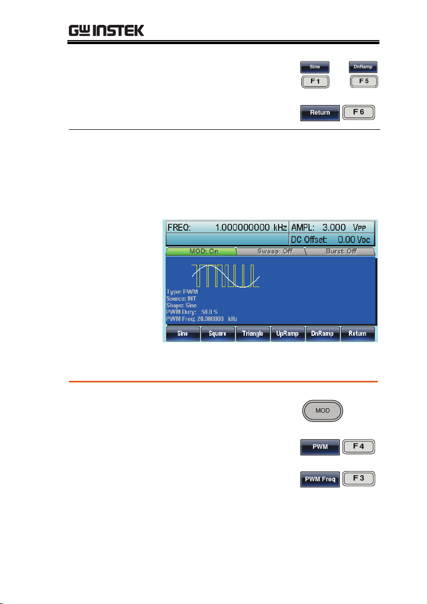
Modulating Waveform Frequency
Panel Operation
1. Select MOD.
2. Press F4 (PWM).
3. Press F3 (PWM Frequency).
4. The PWM Freq parameter will become
highlighted in the Waveform Display area.
93
Page 94
AFG-3000 Series User Manual
Range PWM Frequency 2mHz~20kHz
5. Use the selector keys and
scroll wheel or number pad
to enter the PWM
frequency.
6. Press F1~F3 to select the
frequency unit range.
Default 20kHz
/
~
Modulation Duty Cycle
Duty function is used to set the duty cycle as percentage.
Panel Operation
1. Press the MOD key.
2. Press F4 (PWM).
3. Press F2 (Duty).
94
4. The Duty parameter will become highlighted
in the waveform display area.
Page 95
MODULATION
Range Duty cycle 0% ~ 100%
Note Pulse waveforms can be modulated with an external
5. Use the selector keys and
scroll wheel or number pad
to enter the Duty cycle.
6. Press F1 (%) to select
percentage units.
Default 50%
source using the external source function. When using
an external source the pulse width is controlled by the
± 5V MOD INPUT terminal.
PWM Source
The AFG-3000 accepts internal and external PWM sources. Internal
is the default source for PWM sources.
Panel Operation
1. Press the MOD key.
2. Press F4 (PWM).
3. Press F1 (Source).
95
Page 96

AFG-3000 Series User Manual
~
External Source
Note If an external modulation source is selected, pulse
4. To select the source, press
F1 (Internal) or F2
(External).
5. Press F6 (Return) to return
to the menu.
Use the MOD INPUT terminal
on the rear panel when using an
external source.
width modulation is controlled by the ± 5V from the
MOD INPUT terminal on the rear panel. For example,
if modulation depth is set to 100%, then the
maximum pulse width occurs at +5V, and the
minimum pulse width at -5V.
96
Page 97

MODULATION
Frequency Sweep
The function generator can perform a sweep for sine, square or ramp
waveforms, but not noise, and pulse. When Sweep mode is enabled,
Burst or any other modulation modes will be disabled. When sweep
is enabled, burst mode is automatically disabled.
In Sweep mode the function generator will sweep from a start
frequency to a stop frequency over a number of designated steps. If
manual or external sources are used, the function generator can be
used to output a single sweep. The step spacing of the sweep can
linear or logarithmic. The function generator can also sweep up or
sweep down in frequency.
97
Page 98

AFG-3000 Series User Manual
~
Selecting Sweep Mode
The Sweep button is used to output a sweep. If no
settings have been configured, the default settings
for output amplitude, offset and frequency are
used.
Setting Start and Stop Frequency
The start and stop frequencies define the upper and lower sweep
limits. The function generator will sweep from the start through to
the stop frequency and cycle back to the start frequency. The sweep
is phase continuous over the full range sweep range (100μHz-
80MHz: AFG-3081/50MHz: AFG-3051).
Panel Operation
Start
Stop
98
1. Press the SWEEP key.
2. To select the start or stop
frequency, press F3 (Start)
or F4 (Stop).
3. The Start or Stop parameter will become
highlighted in the waveform display area.
Page 99

MODULATION
Range Sweep Range
Note
4. Use the selector keys and
scroll wheel or number pad
to enter the Stop/Start
frequency.
5. Press F1~F5 to select the
Start/Stop frequency units.
100μHz~80MHz(3081)
100μHz~50MHz(3051)
(Sine/Square)
100μHz~1MHz (Triangle)
Start - Default 100Hz
Stop - Default 1kHz
To sweep from low to high frequencies, set the
start frequency less than the stop frequency.
To sweep from high to low frequencies, set the
start frequency greater than the stop frequency.
When marker is off, the SYNC signal is a square
wave with a duty cycle of 50%. At the start of the
sweep, the SYNC signal is at a TTL low level that
rises to a TTL high level at the frequency midpoint.
The frequency of the SYNC signal is equal to the
sweep time.
When marker is on, at the start of the sweep, the
SYNC signal is at a TTL high level that drops to a
TTL low level at the marker. The SYNC signal is
output from the mark output terminal.
~
99
Page 100

AFG-3000 Series User Manual
~
Center Frequency and Span
A center frequency and span can be set to determine the upper and
lower sweep limits (start/stop).
Panel Operation
Span
Center
1. Press the SWEEP key.
2. Press F6 (More).
3. To select span or center,
press F1 (Span) or F2
(Center).
4. The Span or Center parameter will become
highlighted in the Waveform Display area.
5. Use the selector keys and
scroll wheel or number pad
to enter the Span/Center
frequency.
/
100
6. Press F1~F5 to select the
Start/Stop frequency units.
~
 Loading...