

Gullco SAM CM-02-250 User Manual
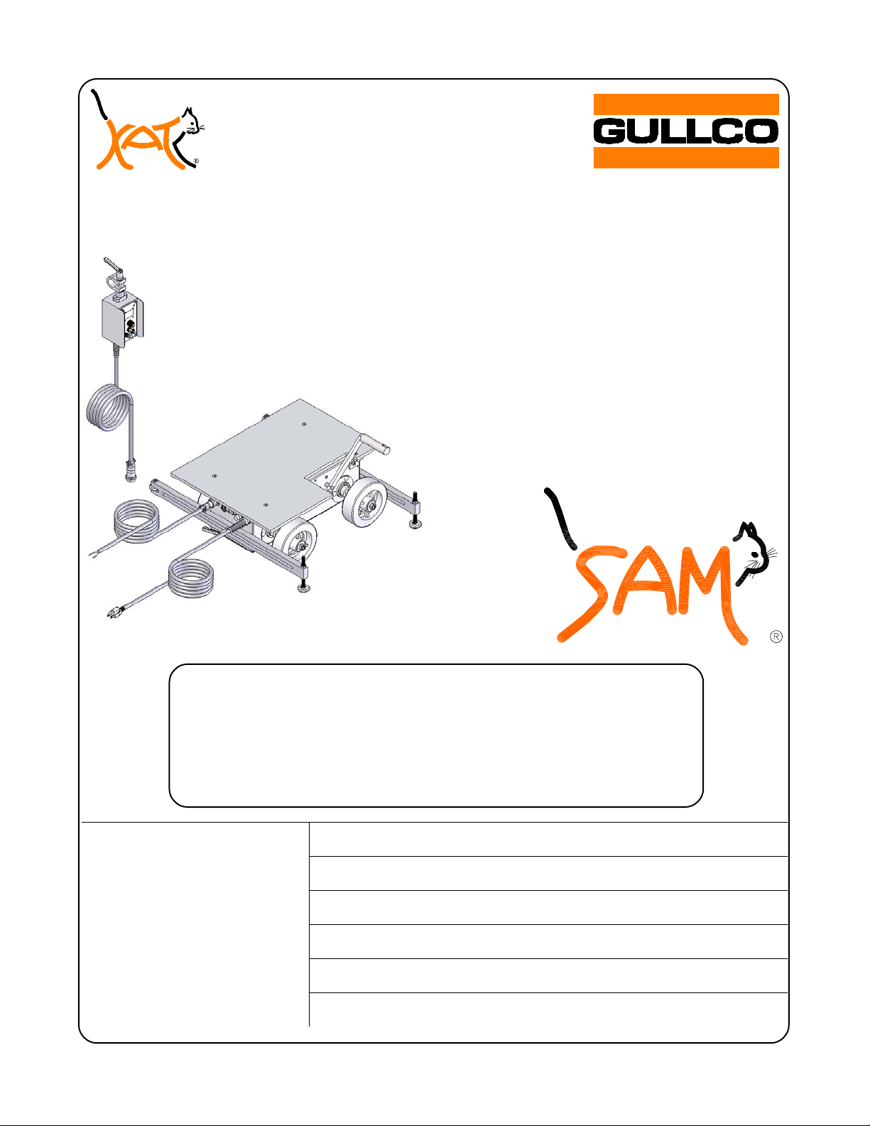
“SAM®”
(SUB ARC MOGGY)
PORTABLE FRICTION
DRIVE TRAVEL
CARRIAGE
MODEL:
GM-02-250
PARTS LIST
&
OPERATING INSTRUCTIONS
Website: www.gullco.com
Distributed by:
Phone: 905-953-4140 Fax: 905-953-4138 e-mail: sales@gullco.com
Phone: 440-439-8333 Fax: 440-439-3634 e-mail: ussales@gullco.com
Phone: +44 1257-253579 Fax: +44 1257-254629 e-mail: sales@gullco.co.uk
Phone: 61 (0) 7 3348-5515 Fax: 61 (0) 7 3348-5510 e-mail: ausales@gullco.com
Phone: 91-20-65260382 Fax: 91-20-26836656 e-mail: India.lo@gullco.com
GULLCO INTERNATIONAL LIMITED – CANADA
GULLCO INTERNATIONAL INC. – U.S.A.
GULLCO INTERNATIONAL [U.K.] LIMITED - EUROPE
GULLCO INTERNATIONAL PTY LIMITED - AUSTRALIA
GULLCO INTERNATIONAL LIMITED – INDIA
GULLCO INTERNATIONAL SHANGHAI – LIMITED
Phone: +8621-50460341 Fax: +8621-50463554 e-mail: c.zhang@gullco.com
Revised: September 8, 2010 GD-066.doc


SAFETY INSTRUCTIONS
Although the Gullco "SAM®" carriage is manufactured for safe and dependable operation, it is
impossible to anticipate those combinations of circumstances, which could result in an accident. An
operator of this equipment is cautioned to always practice "Safety First" during each phase of
operation, setup and maintenance.
Read and understand this whole manual before operating or performing service of this equipment.
Become familiar with the machines operation, applications and limitations. Keep this manual in a
clean and readily available location.
This equipment is normally used to automate / semi-automate welding processes. These
processes usually have any combination of the following; bright and hot arcs, flying sparks, fumes,
ultraviolet and infrared radiated energy, hot work-pieces, compressed gases, etc.. The onus is on
the operator of this equipment to know, understand and follow all the safety precautions associated
with the process being used.
A careless operator invites troubles, and failure to follow safety practices may cause serious injury
or even death. Important safety precautions are given in the following:
Electrical Shock Prevention
¾ Do not use this equipment in damp or wet locations.
¾ Do not expose this equipment to rain.
¾ Never carry this equipment by the cables or pull the cables to disconnect from the
receptacle.
¾ Keep all cables from heat, oil and sharp edges.
¾ Inspect all cables periodically and replace if damaged.
¾ Inspect the security of all cables periodically and repair if loose.
¾ Disconnect the power cord when not in use.
¾ Disconnect the power cord positively
of the equipment.
to prevent electrical shock before repair and service
Bodily Injury Prevention
¾ Do not wear loose clothing, jewellery and loose, long hair, which may get caught into
automatic systems or moving parts.
¾ Keep handles & lifting points dry, clean, free from oil & grease and in good repair.
¾ Do not operate this equipment if ill or drowsy from medication or fatigue.
¾ Do not lift this machine if equipped with heavy accessories or welding cables attached.
¾ Lift machine only with equipment of adequate lifting capacity.
¾ Never lift or suspend the machine over personnel.
¾ Always keep this equipment clean and in good working order.
¾ Report any unsafe condition for immediate correction.
1
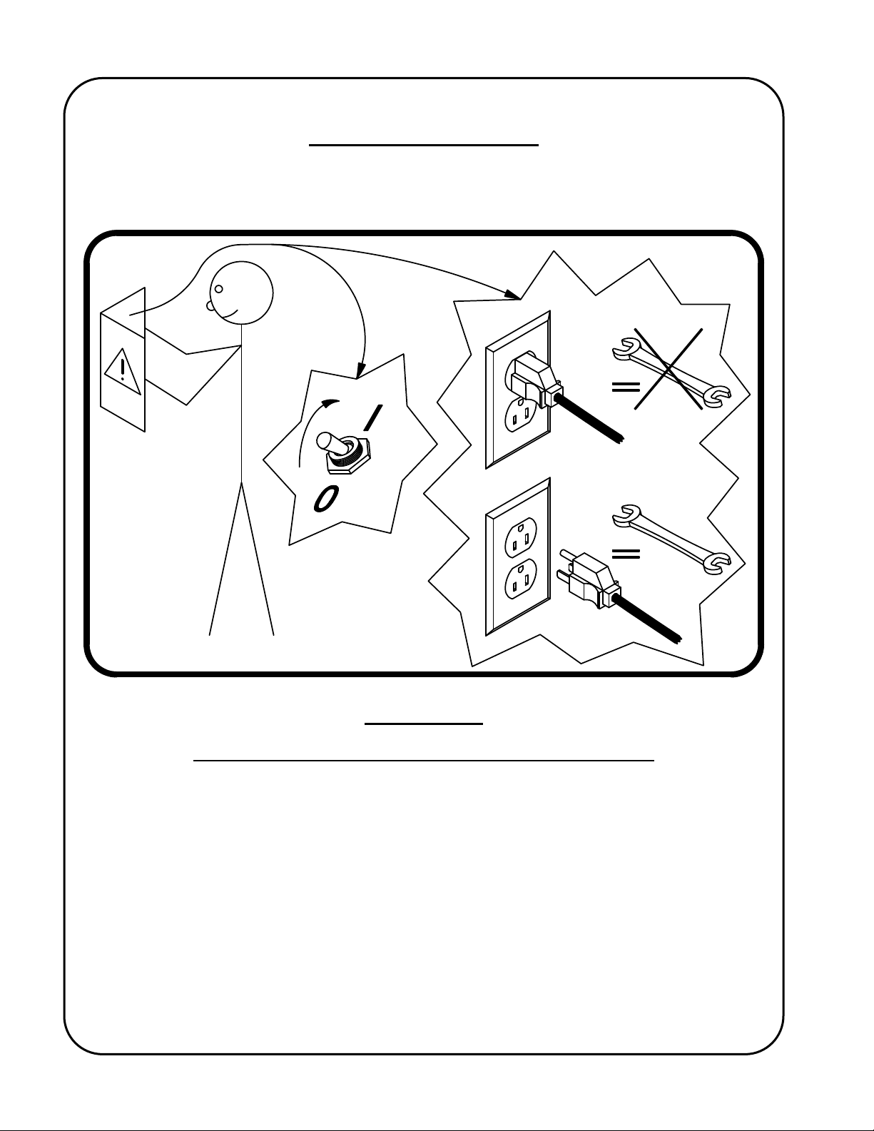
SAFETY PRECAUTIONS
The following cautionary/warning label is attached to each SAM® carriage and its intent is to instruct
all those concerned to read the manual before turning the unit on and before performing service.
Also, positively disconnect the unit from all power supplies before servicing!
IMPORTANT
READ THIS BEFORE OPERATING THE SAM® CARRIAGE
Ensure that an adequate and well-maintained weld return path is provided with good electrical
contact. Failure to do so may result in the welding current passing through the carriage and
damaging the wiring and electrical components.
ALL THE SAFE PRACTICES AND PRECAUTIONS MAY NOT BE GIVEN IN WRITING. SOME
ARE BASED ON COMMON SENSE, BUT OTHERS MAY REQUIRE TECHNICAL
BACKGROUND TO EXPLAIN.
2
SAM® CARRIAGE DETAILS® CARRIAGE DETAILS
This manual covers the parts lists, the operation instructions and the maintenance requirements of
the following Gullco SAM
Portable Friction Drive Travel Carriage:
®
GM-02-250-A (42 VAC), GM-02-250-B (115 VAC), GM-02-250-C (230 VAC)
MODEL OVERVIEW
The part number GM-02-250-(A, B or C) is used to
order a complete GULLCO SAM
carriage system and comes complete with the
Gullco carriage, carriage control pendant, mounting
plate, guide wheel assemblies.
sub arc welding
®
3
SPECIFICATIONS
Speed Range:
Maximum Incline:
Supply Voltage:
Drive Motor:
Weight of GM-02-250 carriage:
Complies with:
4 – 66.1 in/min [10 - 168 cm/min]
30º Depending on mounting configuration
42VAC or 115VAC or 230VAC, single phase, 50/60Hz 200 watts
24 VDC permanent magnet gear motor.
70 Lbs. [31.75 Kg.]
CE Certification.
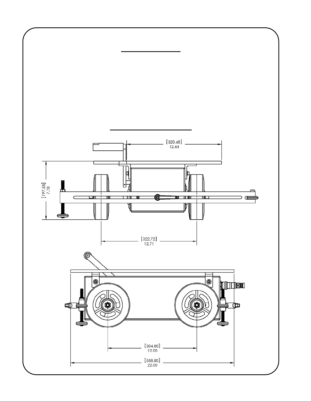
GENERAL DIMENSIONS
4
GENERAL DESCRIPTION
The Gullco GM-02-250 SAM® carriage is a portable, four wheeled, friction drive, submerged arc
welding travel carriage. It is an electrically powered, self propelled carriage that travels in forward
and reverse directions at precisely controlled speeds. It consists of a 24 VDC permanent magnet
gear motor which engages with the wheel axles through chain and sprocket arrangements which
allows both axles to impart a tractive effort through the four rubber tired, friction drive wheels. The
motor’s clutch mechanism in engaged and disengaged through a foot operated lever.
Safety is greatly enhanced by the use of Gullco’s low voltage (24 VDC), highly advanced carriage
drive and control system, which incorporate a closed loop tach feedback system to ensure precise
carriage travel speeds.
INTENDED FORESEEN USAGE
The Gullco heavy duty SAM® is intended to automate and improve the quality of Submerged Arc
welding operations. The SAM
always drive the carriage slightly into the vertical member (usually either the vertical piece of a fillet
joint or a template/fence placed parallel to the joint). Using the Gullco SAM
will add accuracy and uniformity to welding operations while increasing productivity. Typical
applications include shipbuilding, offshore construction, steel fabrication industries, etc...
is normally guided by adjustable guide wheels which are set to
®
travel carriage system
®
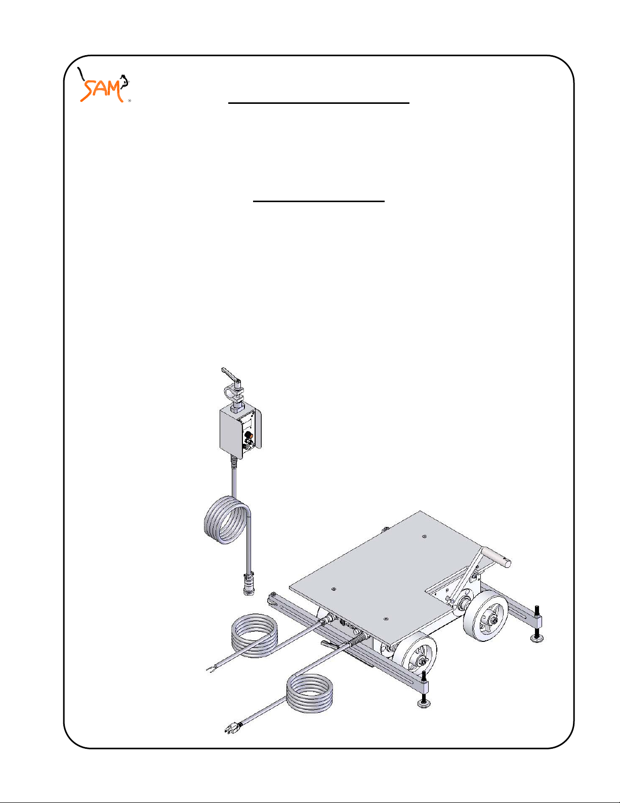
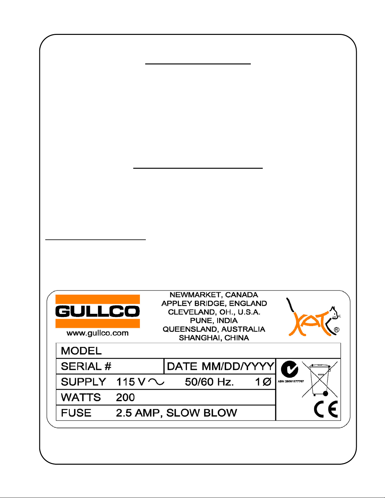
ELECTRICAL CONNECTION
WARNING! Ensure proper AC earth grounding of the Gullco SAM® carriage and all auxiliary
equipment (where applicable), before applying power. Failure to do so may
invalidate the Gullco Warranty.
The label shown below is typical of the product label applied to the SAM® carriage:
The sketch below diagrammatically shows the arrangement of the electrical cable connections.
Each multi-pin connector is different to prevent incorrect connection:
5
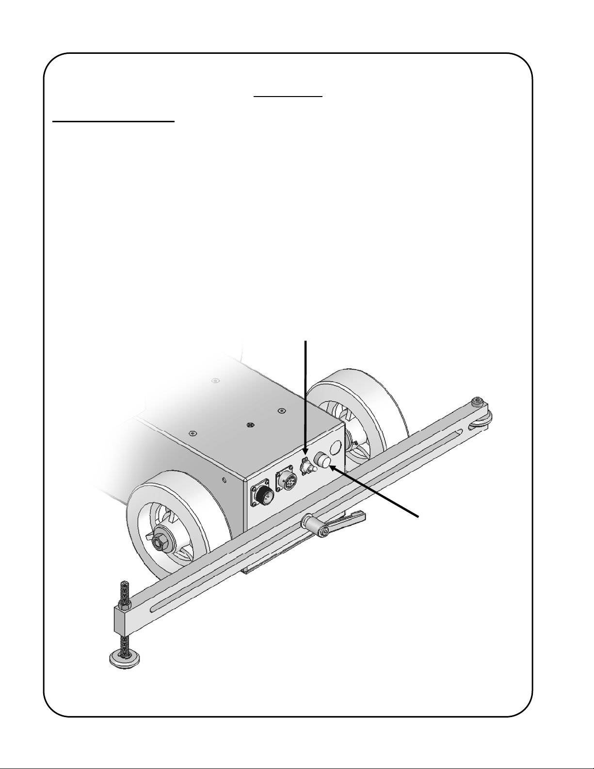
OPERATION
Local Control Devices
The power On/Off switch is used to disconnect the power to the rest of the control circuitry.
I = on, O = off.
WARNING! The motor control must not be continually started and stopped by the removal and
reapplying of power to the control. Turning the power off to the control will not
provide instant braking and continued use will damage the control. Allow ten (10)
seconds after the removal of power before reapplying the power to the motor control.
The fuse holder allows accessibility to the main fuse by pushing the cap in towards the main body
and twisting in a counter-clockwise direction.
On/Off Switch
Fuse Holder
6
A
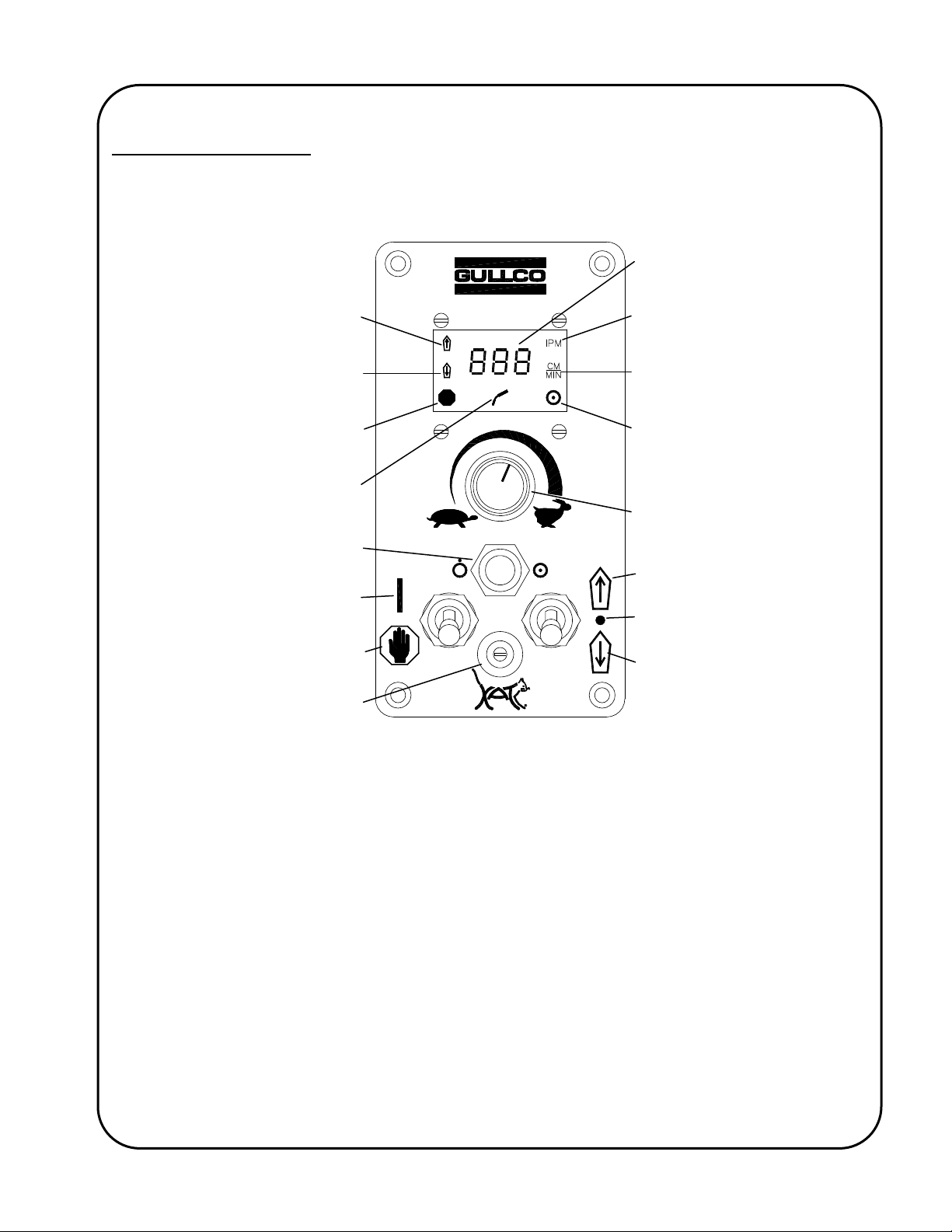
GSP Control Overview
The following section provides operational details of the Gullco GSP-2001-10 microprocessor motor
control used with the GM-02-250 SAM
portable friction drive travel carriages.
®
Forward Motion Commanded
Reverse Motion Commanded
Hold (Stop) Mode Active
rc Signal Active
Cycle Push Button
(Extended or Recessed)
Control in Run Mode
Control in Hold (Stop) Mode
Program Variable Selector Switch
(Extended or Recessed)
Speed & Parameter Value
Display
Speed Display Calibrated in
Inches per Minute
Speed Display Calibrated in
Centimeters per Minute
Auto Cycle Mode (Constant)
Programming mode (Flashing)
Manual Mode (Absent)
Speed Adjustment
Counter-Clockwise = Slower
Clockwise = Faster
Command Forward Motion
Neutral
Command Reverse Motion
The following provides a brief description of the GSP controls (refer to the above sketch):
The Cycle Push Button – is a momentary device, which when pressed for one second while the
Run/Stop switch is in the Stop position, will toggle between Manual Mode (Hnd) and Automatic
Mode (Aut). When in Automatic Mode the Auto Cycle Mode LED will be illuminated.
Button is also used to increment/decrement the values/settings of the program variables (refer to the section
“Programming The Automatic Cycle Parameters/Variables” later in this manual for further details of this
function).
The Cycle Push
The Run/Stop Switch – is used to start and stop the “SAM” carriage in either Manual Mode or
Automatic Mode. The Hold (Stop) position is also used to reset most error codes once they have
been rectified.
7

The Forward/Neutral/Reverse Switch – is used to select the travel direction desired in both Manual
Mode and Automatic Mode.
used to select decrement as the method of changing the values/settings of the program variables (refer to the
section “Programming The Automatic Cycle Parameters/Variables” later in this manual for further details of
this function).
The Speed Adjustment Knob - is used to increase (clockwise) or decrease (counter-clockwise) the
travel speed of the carriage, both in Manual Mode and Automatic Mode. The carriage will travel at
full speed during the no-weld part of a stitch cycle. The speed display will show the set speed when
the Run/Stop switch is in the Stop position and the Forward/Neutral/Reverse switch is in the Neutral
position.
The Program Variable Selector Switch – is a ten position rotary switch, used to set some of the
values and settings which apply to the Automatic Cycle. This selector switch is an extended rotary
switch.
for further details of this selector switch.
Refer to the section “Programming The Automatic Cycle Parameters/Variables” later in this manual
Please refer to the Technical Manual and its supplemental manual (GD-031) “Technical Information
For The Gullco “GSP” Micro-Processor Based, 24 Volt DC Motor Control” (the pages are numbered
with a prefix of “T-“), for additional, more comprehensive details than those provided in the following
overview.
The Forward position is used to select increment, while the reverse position is
GSP CONTROL TECHNICAL INFORMATION
The GSP-2010-10 microprocessor based motor control is a 24 vdc, full “H”-Bridge, pulse width
modulation control with regenerative braking. Inside the chassis of the SAM
supply which converts the 42/115/230 VAC from the power source to a 30 to 38 vdc supply.
These controls can either operate with or without a closed loop tach feed back system attached to
the armature of the motor. A tach feed back is normally recommended as it allows the motor
control to constantly monitor and correct the speed of the motor providing accurate speed control
regardless of any variance in loading. Open loop (i.e. no tach feed back) may be acceptable for
manual motor operation in situations where; the motor sensor is awaiting replacement; the motor
sensor is susceptible to failure due to an exceptionally harsh environment; or where accurate
calibrated speed is not required and the loading of the motor is constant.
Various input and output ports are provided which are either optically coupled or transistor outputs.
The ports that are applicable to this version of the control are described in detail later in this
manual.
Important Notes:
The motor control must not be continually started and stopped by the removal and reapplying of
power to the control. Turning the power off to the control will not provide regenerative braking and
continued use will damage the control.
carriage is a power
®
Allow ten (10) seconds after the removal of power before reapplying the power to the "GSP" control.
The “Current Limit” (motor overload protection) on this product is typically factory preset to 8 Amps
(unless specifically requested at time of order). If a specific application requires that this be
8

changed, please refer to the section which describes the “Motor Control Variables, Rotary Switch”,
later in this manual.
The GSP-2004 microprocessor chip used in these controls is Electrostatic Discharge Sensitive.
Suitable ESD precautions must be adhered to when handling the control and especially the
microprocessor chip. Failure to comply may result in immediate or latent failure.
9
 Loading...