

Page 1
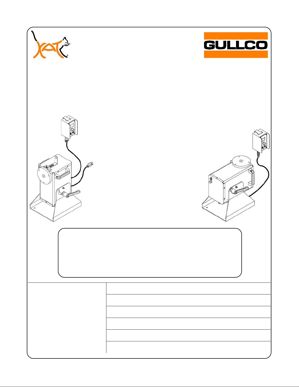
AUTOMATIC CYCLE
WELDING
POSITIONER
(USING GULLCO GSP-2000
SERIES CONTROLS)
MODELS:
GP-250
GPP-250
GP-350
OPERATING
INSTRUCTIONS
Website: www.gullco.com
Distributed by:
GULLCO INTERNATIONAL LIMITED – CANADA
GULLCO INTERNATIONAL INC. – U.S.A.
GULLCO INTERNATIONAL [U.K.] LIMITED - EUROPE
GULLCO INTERNATIONAL PTY LIMITED - AUSTRALIA
GULLCO INTERNATIONAL LIMITED – INDIA
GULLCO INTERNATIONAL SHANGHAI – LIMITED
Revised: February 28, 2013 GD-043-O
Page 2

Page 3
SAFETY INSTRUCTIONS
Although the Gullco AutoCycle welding positioner is manufactured for safe and dependable
operation, it is impossible to anticipate those combinations of circumstances, which could result in
an accident. An operator of the AutoCycle welding positioner is cautioned to always practice
"Safety First" during each phase of operation, setup and maintenance.
Read and understand the whole Operating Instructions manual (as well as the additional Technical
manual complete with the supplementary GSP Control Manual, “GD-031”) before operating or
performing service of this equipment. Become familiar with the machines operation, applications
and limitations. Keep the operation manual in a clean and readily available location.
This equipment is normally used to automate / semi-automate welding or cutting processes. These
processes usually have any combination of the following; bright and hot arcs, flying sparks, fumes,
ultraviolet and infrared radiated energy, hot work-pieces, compressed gases, etc.. The onus is on
the operator of this equipment to know, understand and follow all the safety precautions associated
with the process being used.
A careless operator invites troubles, and failure to follow safety practices may cause serious injury
or even death. Important safety precautions are given in the following:
Electrical Shock Prevention
Do not use this equipment in damp or wet locations.
Do not expose this equipment to rain.
Do not touch electrically live parts or electrode with skin or wet clothing.
Insulate yourself from the work and ground.
Never carry this equipment by the cables or pull the cables to disconnect from the receptacle.
Keep all cables from heat, oil and sharp edges.
Inspect all cables periodically and replace if damaged.
Inspect the security of all cables periodically and repair if loose.
Disconnect the power cord when not in use.
Disconnect the power cord positively to prevent electrical shock before repair and service of the
equipment.
Bodily Injury Prevention
Do not wear loose clothing, jewellery or loose, long hair which may get caught into automatic systems
or moving parts.
Keep equipment (especially lifting handles) dry, clean and free from oil & grease.
Ensure that the AutoCycle positioner is well secured to the bench, tabletop, etc., to prevent it from
tipping over when subjected to over hung loading.
Never loosen the tilt-locking lever, nor try to tilt the rotary welding table, when there is a load mounted
to the table generating large radial moments.
Keep hands away from the rotary table when it is in motion, or when there is the slightest possibility of
motion.
Wherever possible, avoid mounting devices, etc., that protrude from the rotating mass, and pose
possible pinch-points.
Make certain that work-piece/mounting device protrusions will not strike the floor, positioner frame or
any other object during rotation.
There should only ever be one (1) operator working at the machine at any given time.
Do not operate this equipment if drowsy from medication or fatigue.
Do not lift the machine with heavy accessories or cables attached and only lift using adopted safe
lifting standards and practices.
1
Page 4
SAFETY PRECAUTIONS
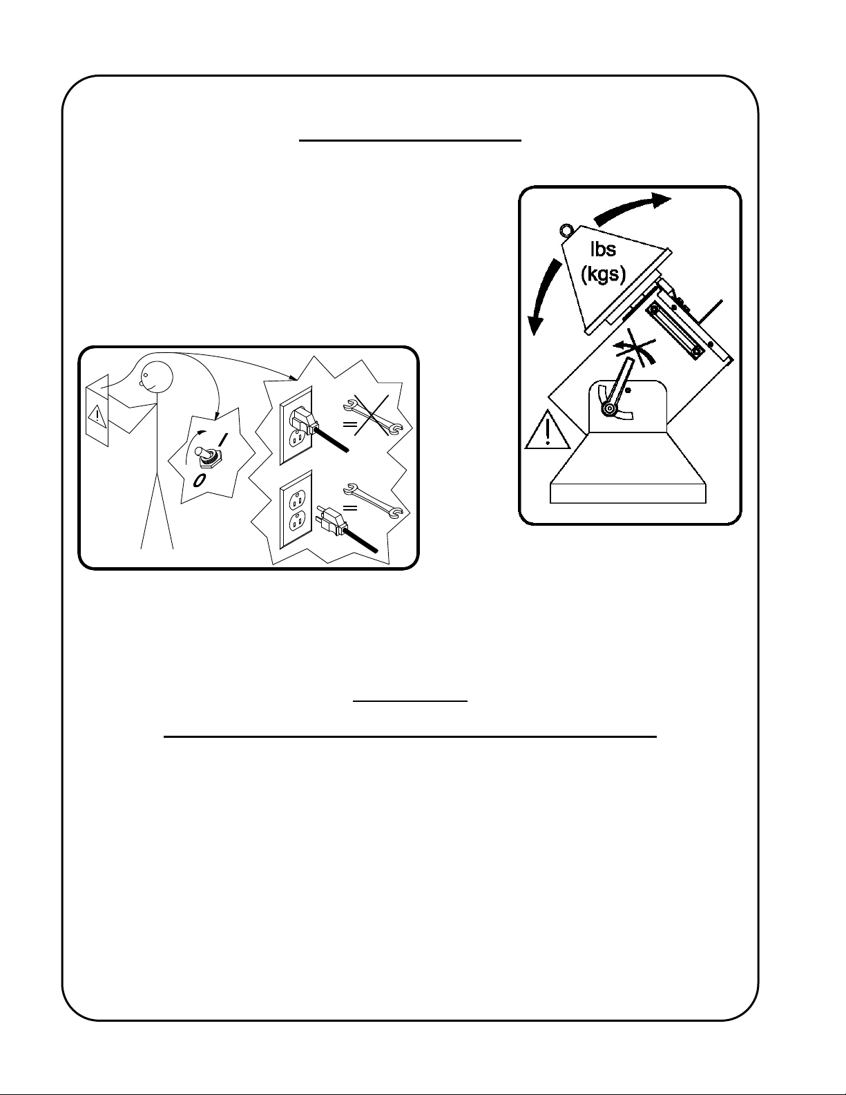
The following cautionary/warning labels are attached to each welding positioner:-
The adjacent label pictorially represents the following:
Warning:-
Do not loosen the tilt clamp lever when there is a load
applied to the table. This may result in an unexpected
radial movement!
The above label pictorially represents the following:
Warning:-
Read the manual before turning the unit on and before performing service. Also, positively
disconnect the unit from all power supplies before servicing!
IMPORTANT
READ THIS BEFORE OPERATING THE WELDING POSITIONER
When used with electric arc welding or cutting equipment, ensure that an adequate and wellmaintained power return path is provided with good electrical contact. Failure to do so may result in
the welding/cutting current passing through the Positioner and damaging the wiring and electrical
components.
Important information regarding safety and operation of the “GSP” motor control used in the
AutoCycle Positioner is contained in a supplemental manual attached at the end of the Technical
Manual. It is equally important to read, understand and apply the information contained within that
manual. The supplemental manual (GD-031) has a title “Technical Information For The Gullco
“GSP” Micro-Processor Based, 24 Volt DC Motor Control”, and it’s pages are numbered with a
prefix of “T-“.
ALL THE SAFE PRACTICES AND PRECAUTIONS MAY NOT BE GIVEN IN WRITING. SOME
ARE BASED ON COMMON SENSE, BUT OTHERS MAY REQUIRE TECHNICAL
BACKGROUND TO EXPLAIN.
2
Page 5
AUTOCYCLE WELDING POSITIONER
This parts list covers the operation and maintenance requirements of the following Gullco
AutoCycle welding positioners:
GP-250-M, GP-250-H, GPP-250-M, GPP-250-H, GP-350-M & GP-350-H
GENERAL DESCRIPTION
The Gullco AutoCycle welding positioners are electrically powered, rotary turn tables, that consist of
a rotary spindle complete with mounting flange, drive and tilt mechanisms, a microprocessor based,
pulse width modulation motor control and a 7-1/2 feet (2.3 mtr.) power cable and a range of options,
as detailed on the following pages. The positive drive of the rotary table is obtained from a single
stage chain and sprocket reduction, driven by a low voltage permanent magnet motor and gearhead power unit assembly. The microprocessor motor control offers operator interface of start,
stop, clockwise rotation, neutral, counter-clockwise rotation and infinitely variable control of the
speed, within the range of the model, as well as an L.E.D. display indicating rotational speed in
revolutions per minute and operational status. The GP-250, GPP-250 & GP-350 series of
AutoCycle welding positioner provides programmable automatic welding cycles (including stitch
welding) and through the use of optional equipment can interface with such items as welding trigger
signals, pneumatic gun positioning slides, manual activation footswitches, and gas purge solenoids.
Safety is greatly enhanced by the use of Gullco's low voltage (24 V) control and power supply
system that is available in three line voltage inputs. I.e. 42, 115 and 230 VAC, single phase, 50/60
Hz, or any unregulated 24 VDC power supply at 220 watts of power. A power supply on/off
isolation switch is provided. The rotation speed is electronically controlled using an optical
tachometer located on the back of the gear-motor and is infinitely variable in both clockwise and
counter-clockwise directions, within the range of the model, by a rotary speed adjustment encoder
located on the remote control faceplate of the AutoCycle welding positioner. Table tilt is manually
set at any desired angle, from 0º through 90°, quickly and easily.
Purge equipped models have a 1/4" (6.4mm) hole through the center of the table spindle and a
rotary gas coupling mounted to the rear of the spindle, providing a female 1/4" N.P.T. gas inlet port.
INTENDED / FORESEEN USAGE
Gullco AutoCycle welding positioners are widely applied to reduce the cost of welding
circumferential components, such as pipe flanges and fittings. They are compact, portable and
provide fast positioning and smooth rotation.
Through automation or semi-automation, the quality, efficiency and repeatability of the weld
produced is greatly improved. Detrimental factors such as poor or awkward accessibility, operator
fatigue, or inconsistent workmanship are eliminated. Required quality levels are consistently
attained and productivity and profitability increased.
3
Page 6
OPERATION
Note: The electrical and mechanical installation of the AutoCycle positioner is explained in the
Technical Manual.
Through the use of the optical tachometer closed loop feedback circuitry, the motor control can
obtain constant speed control of the AutoCycle welding positioner, as well as determine the amount
of rotational distance travelled. The motor and the control operate on 24 VDC, supplied by a power
supply located in the base of the positioner tower. Therefore, all operator interface devices (except
the power on/off switch) are subjected to signal level voltages only.
Local Control Devices
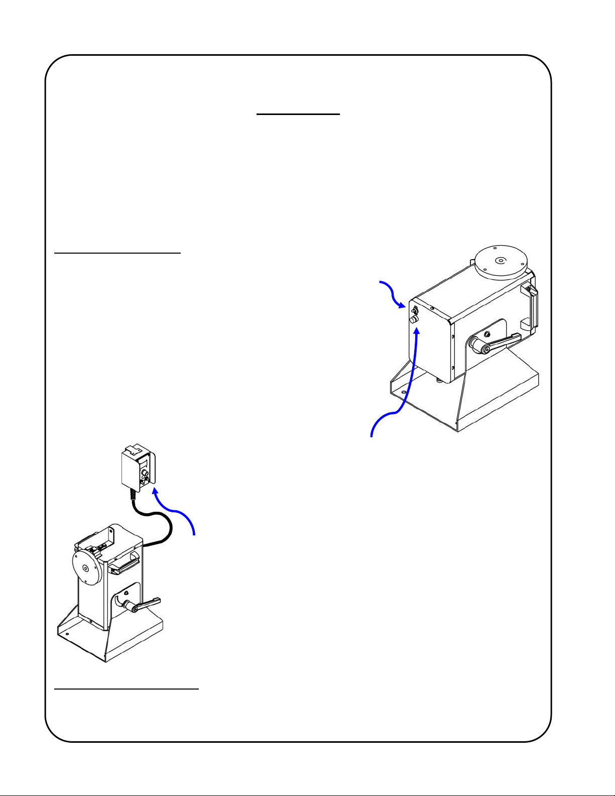
The power On/Off switch is located at the bottom of the positioner
tower and is used to disconnect the power to the rest of the
control circuitry.
I = On, O = Off.
WARNING! The motor control must not be continually started
and stopped by the removal and reapplying of
power to the control. Turning the power off to the
control will not provide instant braking and
continued use will damage the control. Allow ten
(10) seconds after the removal of power before
reapplying the power to the motor control.
The fuse holder is located at the bottom of the positioner tower and
allows accessibility to the main AC fuse by pushing the cap in towards
the main body and twisting in a counter-clockwise direction.
The AutoCycle welding positioner typically
microprocessor based motor control, located in a remote pendant
attached to the positioner by 6ft [1.8 Mtrs] of control cable.
*
uses a Gullco GSP-2010-2
*
If requested at time of purchase, a different style of GSP control can be substituted, where the Program
Variable Selector Switch is located under a hole plug in the face plate (reducing the possibility of
unwanted changes to the AutoCycle routine once set).
4
Page 7
5
A
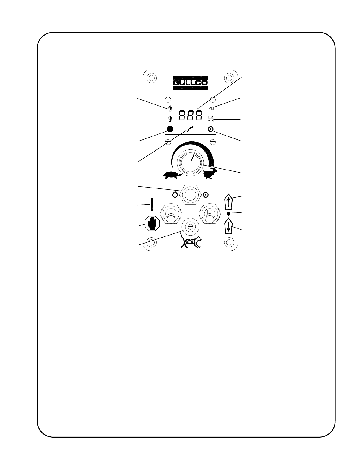
The following provides a brief description of the GSP control (refer to the sketch below):
Speed & Parameter Value
Display
Forward Motion Commanded
Reverse Motion Commanded
Hold (Stop) Mode Active
rc Signal Active
Cycle Push Button
(Extended or Recessed)
Control in Run Mode
Control in Hold (Stop) Mode
Program Variable Selector Switch
(Extended or Recessed)
Speed Display Calibrated in
Inches per Minute
Speed Display Calibrated in
Centimeters per Minute
Auto Cycle Mode (Constant)
Programming mode (Flashing)
Manual Mode (Absent)
Speed Adjustment
Counter-Clockwise = Slower
Clockwise = Faster
Command Forward Motion
Neutral
Command Reverse Motion
The Cycle Push Button
When this momentary device is pressed for one second while the Run/Stop switch is in the
Stop position, the control will toggle between Manual Mode (Hnd) and Automatic Mode
(Aut). When in Automatic Mode the Auto Cycle Mode LED will be illuminated.
The Cycle Push Button is also used to increment/decrement the values/settings of the program
variables (refer to the section “Programming The Automatic Cycle Parameters/Variables” later in this
manual for further details of this function).
The Run/Stop Switch
This is used to start and stop rotation of the positioner in Manual Mode and is used to start
and stop an automatic cycle in Automatic Mode.
The Hold (Stop) position is also used to reset most error codes once they have been rectified.
The Forward/Neutral/Reverse Switch
This is used to select the direction of rotation in Manual Mode and must be in the Neutral
position to allow an automatic cycle.
The Forward position is used to select increment, while the reverse position is used to select
decrement as the method of changing the values/settings of the program variables (refer to the
section “Programming The Automatic Cycle Parameters/Variables” later in this manual for further
details of this function).
Page 8

6
The Speed Adjustment Knob
This adjustment is used to increase (clockwise) or decrease (counter-clockwise) the
rotational speed of the positioner, both in Manual Mode and Automatic Mode. The speed
display will show the set speed when the Run/Stop switch is in the Stop position and the
Forward/Neutral/Reverse switch is in the Neutral position.
The Program Variable Selector Switch
This ten position rotary switch is used to select the various adjustable parameters that are
available to the operator, which determine the functionality and allow fine-tuning of the
automatic cycle operation. If requested at time of purchase, a different style of GSP control
can be substituted, where the Program Variable Selector Switch is located under a hole
plug in the face plate (reducing the possibility of unwanted changes to the automatic cycle
once set).
this manual for further details of this selector switch.
WARNING! Avoid changing the direction of rotation without making sure that rotation comes to a
WARNING! Avoid repeatedly starting and stopping the positioner in quick, short succession, as
Refer to the section “Programming The Automatic Cycle Parameters/Variables” later in
complete stop first. Failure to comply may cause an overload.
this will reduce the life expectancy of the control and the motor.
Manual Operation
To toggle between automatic mode (Aut) and manual mode (Hnd), place the Run/Stop switch in the
Stop position and press and hold the Cycle Push Button until the desired mode is displayed (Aut or
Hnd).
In manual mode (Hnd) the Preset Cycle L.E.D. located in the lower right hand corner of the display
will be extinguished.
Manual mode only permits manual rotation of the turntable. The Forward/Neutral/Reverse switch
selects which direction the positioner will rotate. The Speed Adjustment knob sets the rotary speed.
When the Run/Stop switch is placed in the Run position (and the optional footswitch is depressed,
when installed), the positioner will rotate in the direction and speed set by the
Forward/Neutral/Reverse switch and the Speed Adjustment knob. Travel motion will cease if; the
Run/Stop switch is placed in the Stop position; the Forward/Neutral/Reverse switch is placed in the
Neutral position; the speed is set to zero; or the optional footswitch is released (when installed).
In Manual Mode, the Arc Signal Relay remains de-energized.
The optional remote Start/Stop foot switch [GP-200-024] is used to manually start and stop rotation
of the positioner turntable. Depressing the foot switch will activate rotation and releasing the foot
switch will deactivate the rotation and apply braking. The Run/Stop switch must be in the Run
position and a rotation direction must be selected for the unit to operate when the footswitch is
depressed.
Page 9

7
Automatic Operation
This section refers to parameter settings and values. Details of accessing and changing these
settings and values can be found later in this manual under the section “Programming The
Automatic Cycle Parameters/Variables”.
To toggle between automatic mode (Aut) and manual mode (Hnd), place the Run/Stop switch in the
Stop position and press and hold the Cycle Push Button until the desired mode is displayed (Aut or
Hnd).
In Automatic mode (Hnd) the Preset Cycle L.E.D. located in the lower right hand corner of the
display will be constantly illuminated.
In automatic mode (Aut), every time the Run/Stop switch is placed in the Run position (and the
Forward/Neutral/Reverse switch is in the Neutral position), the programmed automatic cycle will
execute. The optional Start/Stop footswitch is totally ignored in automatic mode. The turntable
welding speed will be set by the Speed Adjustment knob.
If the Run/Stop switch is placed in the Stop position at any time during an automatic cycle, the
automatic cycle will perform a controlled, sequential shut down as described from section 1-12 or 212 depending upon the setting of the programmable Weld Cessation parameter (P. 9).
The automatic cycle is initiated by placing the Run/Stop switch in the Run position. If the
programmable Weld Cessation parameter (P. 9) is set to “2” the automatic cycle will continue as
described in section 2-1 to 2-14. If the Weld Cessation parameter (P. 9) is set to “1” the automatic
cycle will proceed as described in section 1-1 to 1-14.
1. Programmable Weld Cessation (P. 9) = “1” (typical for Mig applications).
1-1. The optional gun slide solenoid relay (connected to CN82 of the GSP control) will be
energized and the programmable Gun Slide Extend Delay (P. 1) timing cycle will
commence. This allows time for the optional pneumatic gun slide [GP-175-030] (where
applicable) to position the welding gun before activating the arc.
1-2. Upon completion of the Gun Slide Extend Delay (P. 1), the optional arc signal relay [GK-
191-P-071] (connected to CN81 of the GSP control) will be energized and the
programmable Rotation Start Delay (P. 2) timing cycle will commence. This provides time
for any pre-flow function as well as allowing the arc to establish prior to commencing the
weld motion.
1-3. Upon completion of the Rotation Start Delay (P. 2), the weld rotation will start to travel in
the forward direction at the speed set by the Speed Adjustment knob.
1-4. If the programmable Stitch Weld parameter (P. 6) is set to Off (continuous weld), the cycle
will continue as described in section 1-12. If the Stitch Weld parameter (P. 6) is set to On
(stitch weld), the cycle will continue as described in section 1-5.
1-5. The weld rotation will stop when the angular rotation reaches the initial value set in the
programmable Stitch Weld Angle parameter (P. 7) or every time it reaches the sum of the
initial Stitch Weld Angle (P. 7) value plus the accumulative sums of each Stitch Weld
Angle (P. 7) and No-Weld Angle (P. 8). The programmable Crater-Fill/Slope-Out Delay
(P. 4) timing cycle will commence. When the programmable Weld Cessation variable (P.
Page 10

8
9) is set to “1”, the Crater-Fill/Slope-Out Delay is used to keep the arc signal active for a
programmable duration, after the rotation has ceased, thereby filling in the weld crater.
1-5-1. Exa mple, the Stitch Weld Angle parameter is set to 20º and the No-Weld Angle is
set to 40º. The weld rotation would stop at 20º, 80º, 140º, 200º etc.
1-6. Upon completion of the Crater-Fill/Slope-Out Delay (P. 4), the optional arc signal relay will
de-energize and the programmable Post Weld Delay (P. 5) timing cycle will commence.
This allows time for any burn-back and or post-flow functions, prior to the table rotating to
the start of the next weld.
1-7. Upon completion of the Post Weld Delay, the no-weld rotation will start in the forward
direction at full speed.
1-8. The no-weld rotation will stop every time that the angular rotation reaches an
accumulative value of the sum of the programmable Stitch Weld Angle (P. 7) and the
programmable No-Weld Angle (P. 8). A fixed delay of 0.7 seconds will then commence.
This delay ensures that the turntable has come to a complete stop, prior to starting the
next weld.
1-8-1. Exa mple, the Stitch Weld Angle parameter is set to 20º and the No-Weld Angle is
set to 40º. The no-weld rotation would stop at 60º, 120º, 180º, 240º etc.
1-9. Upon completion of the fixed delay, the optional arc signal relay will be re-energized and
the programmable Rotation Start Delay (P. 2) timing cycle will commence again. This
provides time for any pre-flow function as well as allowing the arc to establish prior to
commencing the weld motion.
1-10. Upon completion of the Rotation Start Delay (P. 2), the weld rotation will start to travel in
the forward direction at the speed set by the Speed Adjustment knob.
1-11. The cycle will continue as described between section 1-5 and section 1-10 until the total
angular rotation reaches the value set by the programmable Degrees Of Rotation
parameter (P. 3), at which point the cycle will close down as described in section 1-12.
1-12. Regardless of whether the automatic cycle is performing a continuous weld or a stitch
weld routine, when the angular rotation reaches the same value as the programmable
Degrees Of Rotation parameter (P. 3), the rotation ceases and the programmable CraterFill/Slope-Out Delay (P. 4) timing cycle will commence. When the programmable Weld
Cessation variable (P. 9) is set to “1”, the Crater-Fill/Slope-Out Delay is used to keep the
arc signal active for a programmable duration, after the rotation has ceased, thereby filling
in the weld crater
1-13. Upon completion of the Crater-Fill/Slope-Out Delay (P. 4), the optional arc signal relay will
de-energize and the programmable Post Weld Delay (P. 5) timing cycle will commence.
This allows time for any burn-back and or post-flow functions, prior to the retraction of the
optional pneumatic gun positioning slide (where applicable).
1-14. Upon completion of the Post Weld Delay, the optional gun slide solenoid relay will be de-
energized and the automatic cycle will be complete. “End” will be displayed to indicate the
completion.
Page 11

2. Programmable Weld Cessation (P. 9) = “2” (typical for Tig applications).
2-1. The optional gun slide solenoid relay (connected to CN82 of the GSP control) will be
energized and the programmable Gun Slide Extend Delay (P. 1) timing cycle will
commence. This allows time for the optional pneumatic gun slide [GP-175-030] (where
applicable) to position the welding gun before activating the arc.
2-2. Upon completion of the Gun Slide Extend Delay (P. 1), the optional arc signal relay [GK-
191-P-071] (connected to CN81 of the GSP control) will be energized and the
programmable Rotation Start Delay (P. 2) timing cycle will commence. This provides time
for any pre-flow function as well as allowing the arc to establish prior to commencing the
weld motion.
2-3. Upon completion of the Rotation Start Delay (P. 2), the weld rotation will start to travel in
the forward direction at the speed set by the Speed Adjustment knob.
2-4. If the programmable Stitch Weld parameter (P. 6) is set to Off (continuous weld), the cycle
will continue as described in section 2-12. If the Stitch Weld parameter (P. 6) is set to On
(stitch weld), the cycle will continue as described in section 2-5.
2-5. The optional arc signal relay will de-energize when the angular rotation reaches the initial
value set in the programmable Stitch Weld Angle parameter (P. 7) or every time it reaches
the sum of the initial Stitch Weld Angle (P. 7) value plus the accumulative sums of each
Stitch Weld Angle (P. 7) and No-Weld Angle (P. 8). The programmable Crater-Fill/SlopeOut Delay (P. 4) timing cycle will commence. When the programmable Weld Cessation
variable (P. 9) is set to “2”, the Crater-Fill/Slope-Out Delay is used to keep the turntable
rotating for a programmable duration, after the arc signal has been de-activated, providing
a slope-out function.
2-5-1. Exa mple, the Stitch Weld Angle parameter is set to 20º and the No-Weld Angle is
set to 40º. The weld rotation would stop at 20º, 80º, 140º, 200º etc.
2-6. Upon completion of the Crater-Fill/Slope-Out Delay (P. 4), the weld rotation will stop and
the programmable Post Weld Delay (P. 5) timing cycle will commence. This allows time
for any burn-back and or post-flow functions, prior to the table rotating to the start of the
next weld.
2-7. Upon completion of the Post Weld Delay, the no-weld rotation will start in the forward
direction at full speed.
2-8. The no-weld rotation will stop every time that the angular rotation reaches an
accumulative value of the sum of the programmable Stitch Weld Angle (P. 7) and the
programmable No-Weld Angle (P. 8). A fixed delay of 0.7 seconds will then commence.
This delay ensures that the turntable has come to a complete stop, prior to starting the
next weld.
2-8-1. Exa mple, the Stitch Weld Angle parameter is set to 20º and the No-Weld Angle is
set to 40º. The no-weld rotation would stop at 60º, 120º, 180º, 240º etc.
2-9. Upon completion of the fixed delay, the optional arc signal relay will be re-energized and
the programmable Rotation Start Delay (P. 2) timing cycle will commence again. This
9
Page 12
0
(
)
provides time for any pre-flow function as well as allowing the arc to establish prior to
commencing the weld motion.
2-10. Upon completion of the Rotation Start Delay (P. 2), the weld rotation will start to travel in
the forward direction at the speed set by the Speed Adjustment knob.
2-11. The cycle will continue as described between section 2-5 and section 2-10 until the total
angular rotation reaches the value set by the programmable Degrees Of Rotation
parameter (P. 3), at which point the cycle will closedown as described in section 2-12.
2-12. Regardless of whether the automatic cycle is performing a continuous weld or a stitch
weld routine, when the angular rotation reaches the same value as the programmable
Degrees Of Rotation parameter (P. 3), the optional arc signal relay will de-energize and
the programmable Crater-Fill/Slope-Out Delay (P. 4) timing cycle will commence. When
the programmable Weld Cessation variable (P. 9) is set to “2”, the Crater-Fill/Slope-Out
Delay is used to keep the turntable rotating for a programmable duration, after the arc
signal has been de-activated, providing a slope-out function.
2-13. Upon completion of the Crater-Fill/Slope-Out Delay (P. 4), the rotation ceases and the
programmable Post Weld Delay (P. 5) timing cycle will commence. This allows time for
any burn-back and or post-flow functions, prior to the retraction of the optional pneumatic
gun positioning slide (where applicable).
2-14. Upon completion of the Post Weld Delay, the optional gun slide solenoid relay will be de-
energized and the automatic cycle will be complete. “End” will be displayed to indicate the
completion.
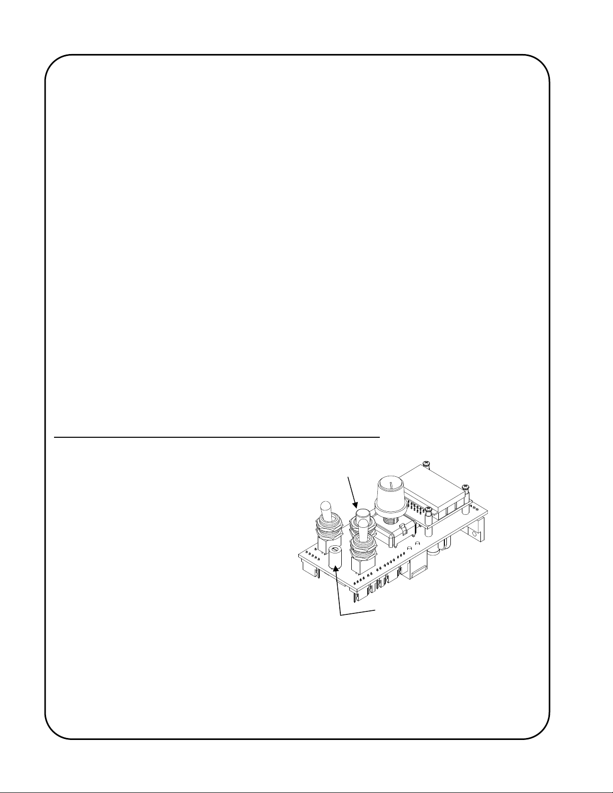
Programming The Automatic Cycle Parameters/Variables
The Program Variable Selector Switch is
used to select the different programmable
parameters that allow the operator to
change their values and settings and so
define how the automatic cycle will
function. The Program Variable Selector
Switch is located between and below the
Run/Stop switch and the
Forward/Neutral/Reverse switch of the
GSP control. The GSP control that is
typically supplied with the AutoCycle weld
positioner has a Program Variable Selector
Switch, which extend through the faceplate
of the control. Other styles of control are
available where the removal of a hole-plug for access and a small flat-bladed screwdriver for
adjustment are required (as shown in adjacent sketch).
Cycle Push Button
Program Variable Selector Switch
Extended or Recessed
shown
Zero (0) (top dead center) is the normal operating location for the switch. When in any position
other than zero (0) the control is in programming mode, the round,
Preset Cycle L.E.D. in the bottom
right hand corner of the display will flash and the motor control will not allow normal operation.
1
Page 13
To make changes to the program variables, turn the power on and place the Run/Stop switch in the
Stop position, then rotate the Program Variable Selector switch to the variable (parameter) to be
altered (the Auto Cycle Mode L.E.D. will flash on and off). The number of the variable parameter
will be displayed when the Forward/Neutral/Reverse switch is in the Neutral position. I.e. “P. 1”, “P.
2”, “P. 3”, etc. To see the current value/setting of the variable, place the Forward/Neutral/Reverse
switch in either the Forward or Reverse position. To increment the value/setting, place the
Forward/Neutral/Reverse switch in the Forward position and press the Cycle Push Button. To
decrement the value/setting, place the Forward/Neutral/Reverse switch in the Reverse position and
press the Cycle Push Button. Pressing the Cycle Push Button briefly will increment/decrement the
value/setting by one, whereas keeping the Cycle Push Button depressed will scroll through the
values/settings until released. The speed display and/or the individual L.E.D.’s will indicate the
chosen value/setting. When all of the program variables are set, place the Program Variable
Selector switch back to the zero position (the Auto Cycle Mode L.E.D. will stop flashing).
The values/settings of the variables are stored on the product/application specific micro-processor
chip. If the chip is replaced, the
values/settings of the variables will
need to be re-entered.
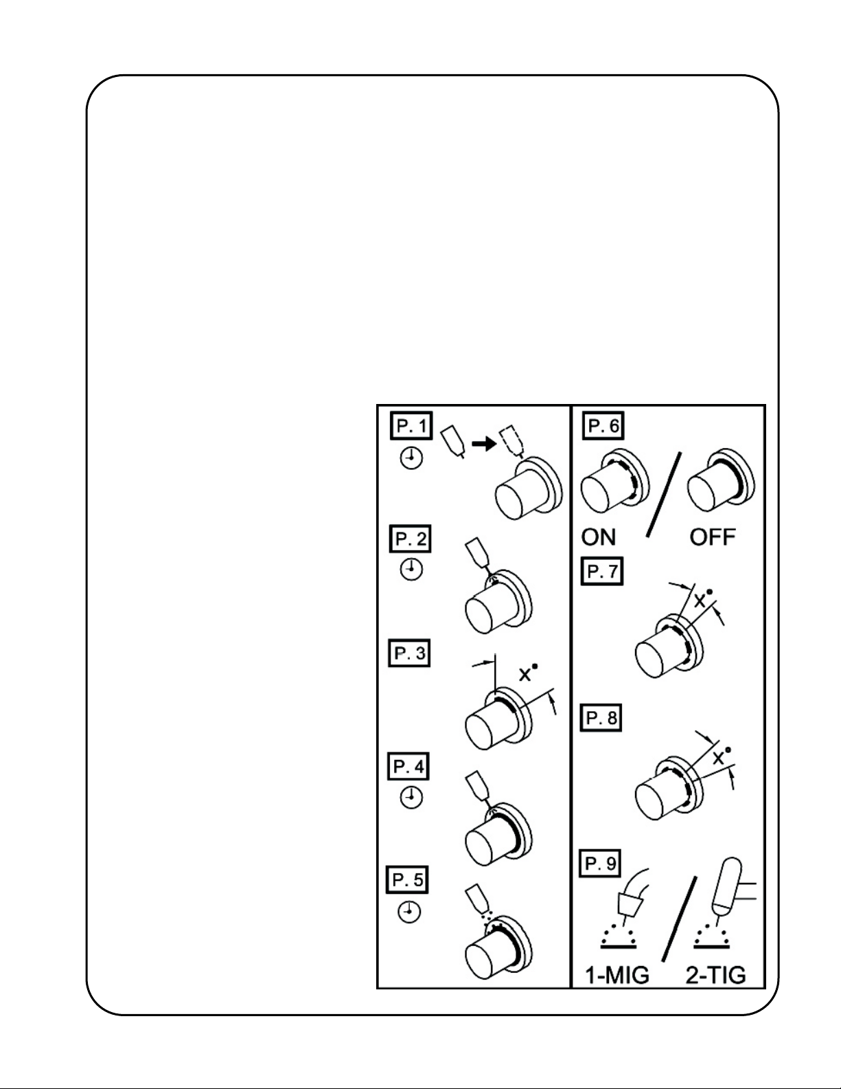
The adjacent label is applied to each
AutoCycle weld positioner to
graphically identify the individual
programmable parameters/variables:
11
Page 14

Description of Programmable Parameters/Variables
The following describes the Program Variable Selector Switch settings for the GSP motor control
using Gullco’s GSP-2004-2 micro-processor chip, as rotated clockwise from zero (0) top dead
center.
P. 0 Normal Operating Position - The control needs to be in this position to allow normal
operation (top dead center).
P. 1 Gun Slide Extend Delay - This sets a delay after the activation of the optional gun
positioning slide solenoid relay, prior to activation of the optional arc signal relay, to allow
the pneumatic slide to position the welding gun before activating the arc. The variable
value range is from 00.0 to 09.9 seconds, in increments of 00.1 seconds.
P. 2 Rotation Start Delay - This sets a delay after the activation of the optional arc signal
relay, prior to starting rotation, to allow for shielding gas pre-flow and to allow the arc to
establish before starting the weld motion. The variable value range is from 00.0 to 09.9
seconds, in increments of 00.1 seconds.
P. 3 Degrees Of Rotation - This sets the total rotation angle that will take place in an
automatic cycle before the final close-down sequence of the welding cycle. The variable
value range is from 045 to 999 degrees, in increments of 001 degree (360º = 1 full rev).
P. 4 Crater-Fill/Slope-Out Delay - When the programmable Weld Cessation (P. 9) variable is
set to “1”, the Crater-Fill/Slope-Out Delay is used to keep the optional arc signal relay
energized for a programmable duration, after the rotation has stopped, providing a
crater-fill function. When the programmable Weld Cessation (P. 9) variable is set to “2”,
the Crater-Fill/Slope-Out Delay is used to keep the turntable rotating for a programmable
duration, after the arc signal has been de-activated, providing a slope-out function. The
variable value range is from 00.0 to 09.9 seconds, in increments of 00.1 seconds.
P. 5 Post Weld Delay - This sets a delay after each crater-fill or slope-out delay (described
above) prior to de-energizing the optional gun positioning slide solenoid relay, or starting
the no-weld rotation (used in stitch welding routines). This is to allow the welding gun to
remain stationary over the end of the weld for any burn-back or post-flow to occur. The
variable value range is from 00.0 to 09.9 seconds, in increments of 00.1 seconds.
P. 6 Stitch Weld (Enable/Disable) - This allows the operator to choose whether the weld will
be continuous (Off) or stitched/spaced (On). If continuous is chosen the parameters P. 7
and P. 8 will not be available to the operator and “- - -” will be displayed. The variable
setting is either On or Off.
P. 7 Stitch Weld Angle – This sets the rotation angle of each stitch weld. The variable value
range is from 001 to 999 degrees, in increments of 001 degree.
P. 8 No-Weld Angle – This sets the rotational angle of each space between stitch welds (no-
weld). The variable value range is from 001 to 999 degrees, in increments of 001
degree.
P. 9 Weld Cessation – This allows the operator to choose the closedown sequence of the
welding process. The variable setting is either:
"1" Crater-fill – Rotation stops prior to de-activation of arc signal (typical for Mig
applications).
"2" Slope-out – Arc signal de-activated prior to stopping the rotation (typical for Tig
applications).
12
Page 15
)
LOADING
Before mounting any load to the positioner, the tilt locking adjustable lever should be tested for
tightness. When loading the work piece onto the table, take account of the weight, centroid
eccentricity and centroid height of both the work piece and all clamping fixtures. When the work
piece is large and its weight is one sided at the peripheral portion, inertia start and stop is severe
and can cause an overload situation. Wherever possible, counterbalance weights should be used
to reduce this stress. Take into consideration the additional weight and distribution of the
counterbalance.
WARNING! Lower work pieces onto the turntable gently. Impact and shock loads are many
times greater than the "dead-weight” of the work-piece. Dropping loads onto the
table can result in damage!
WARNING! Do not use impact or shock techniques to clamp and unclamp self-centering grippers
mounted to the positioner turntable. The shock will be transferred to the drive
system resulting in damage!
ACCESSORIES
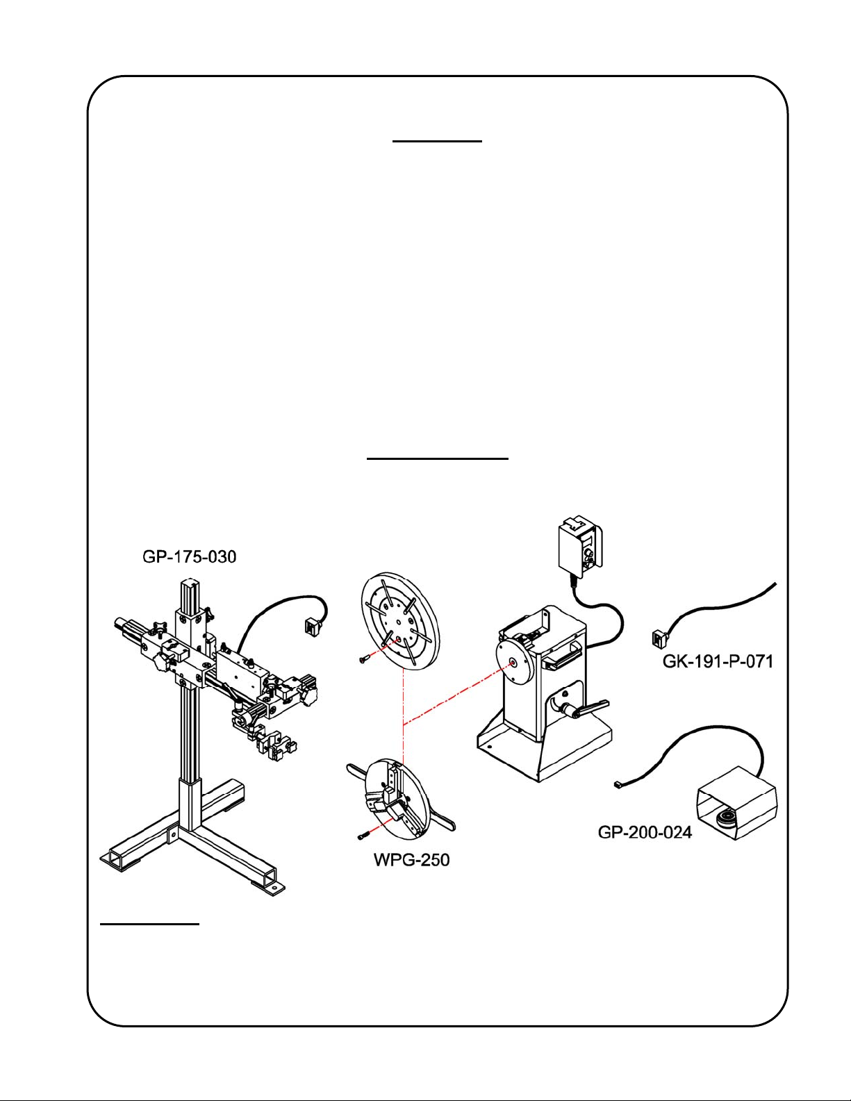
GP-250, GPP-250 OR GP-350
GP-200-016 (GP-250 & GPP-250)
GP-300-002 (GP-350
GK-191-P-071 Arc signal relay kit. This kit provides an internal wiring harness; an isolated relay
and quick connect receptacle circuit board assembly; and an external cable with
mating quick connect plug. It is used to provide an isolated closed circuit signal to
activate the welding/cutting equipment at appropriate times during the automatic
cycle. Arc signal relay kits can be paralleled together to provide simultaneous arc
activation signals to multiple welding/cutting machines.
13
Page 16

GP-175-030 Automatic gun positioning support stand assembly. This kit provides an internal
wiring harness; a 24 VAC output relay and quick connect receptacle circuit board
assembly; a 24 VAC pneumatic solenoid valve complete with control cable with
mating quick connect plug; a 4” [101mm] stroke pneumatic gun positioning slide;
a semi-automatic adjustable gun clamp assembly; a free-standing/bolt-down
support stand, a 1-1/2” [38.1mm] micro-fine rack box and rack arm assembly for
vertical adjustment; a 1-1/2” [38.1mm] micro-fine rack box and rack arm assembly
for horizontal adjustment; a 1-1/8” [28.6mm] micro-fine rack box and rack arm for
horizontal cross adjustment; and an adjustable cable/hose clamp assembly. It is
used to clamp and position the welding gun for repetitive operations as well as
providing automatic gun extension at the start of each automatic cycle and
automatic gun retraction at the end of each automatic cycle to facilitate easy
loading and unloading of the work-pieces.
GP-200-024 Run/Stop footswitch assembly for manual operation. This kit provides a run/stop
footswitch; a footswitch guard cover; a connecting control cable; and strain relief
glands. When activated, the footswitch will provide a run signal to the control
allowing manual rotation when the control is in manual mode (the footswitch has
no affect in automatic mode).
GP-200-016 12” [305 mm] Diameter mounting table. This round mounting table is used to
facilitate direct mounting of components or fixtures and provides six (6) radial
mounting slots and various three (3) hole pitch circle bolt patterns. The mounting
table is quickly and easily mounted on the positioner spindle flange.
GP-300-002 Same as GP-200-016 except that there is a 2.50” diameter centre hole for the
through bore GP-350 positioner.
WPG-250 Gullco Self-Centering Welding Grippers are quickly and easily mounted on the
positioner spindle flange. They are slim but rugged, weighing only about half of
that of a standard chuck, minimizing reduction in positioner capacity. A single
lever provides smooth, positive, self-centering open/close action.
External clamping range = 0.38" [10mm] to 11.25" [286mm]
Internal clamping range = 4.25" [108mm] to 15" [381mm]
Weight 20 Lbs. [9 Kg.]
KR-1000 CSB A free standing support and cutting torch holder assembly. 1-1/8" [28.6mm]
square rack arms and rack boxes provide 11-1/2" [292.1mm] of vertical
adjustment and 10-1/2" [266.7cm] of horizontal adjustment. Supplied with swivel
mounted, standard rack-type cutting torch holder.
KR-2000 CSB Same as above, except uses 1-1/2" [38.1mm] rack arms and rack boxes and
provides 7-1/2" [190.5mm] of vertical and 6-1/2" [165.1mm] of horizontal
adjustment.
KR-1000 WSB A free standing support and welding gun holder assembly. 1-1/8" [28.6mm]
square rack arms and rack boxes provide 11-1/2" [292.1mm] of vertical
adjustment and 10-1/2" [266.7mm] of horizontal adjustment. Supplied with swivel
mounted, adjustable gun holder assembly.
14
Page 17
KR-2000 WSB Same as above, except uses 1-1/2" [38.1mm] rack arms and rack boxes and
provides 7-1/2" [190.5mm] of vertical and 6-1/2" [165.1mm] of horizontal
adjustment.
NOTE: The above cutting torch and welding gun support assemblies can be, and often
are, equipped with one (1) or two (2) Gullco motorized rack arms controlled by a
remote joystick pendant. Ask your local Gullco representative for further details.
ALSO AVAILABLE:
Gullco frequently designs and manufactures custom welding systems, often utilizing the AutoCycle
welding positioner. These systems normally use some, or all of the following; a programmable logic
control, a programmable operator interface (that allows the user to easily adjust any of the timed
and counted preset values etc.), pneumatic or motorized slide/slides, interfacing with
welding/cutting equipment, external safety devices, auxiliary process equipment etc. Your local
Gullco representative would welcome the opportunity to discuss how we may assist in automating
your specific application.
Visit Gullco’s web site, “www.gullco.com”
to see, or request, more product and
application information.
15
Page 18
REVISIONS LIST
November, 2004
Overall First release.
Feb, 2013
Overall Added GP-350 through bore positioner.
ADDITIONAL NOTES
Specifications and products are subject to change without notice.
KAT, Moggy, Sam & KATback are registered trademarks of Gullco International Enterprises Ltd.
Only use genuine/authorized replacement parts.
16
Page 19

Page 20
www.GULLCO.com
 Loading...