

Gullco PK-500-LG-x User Manual
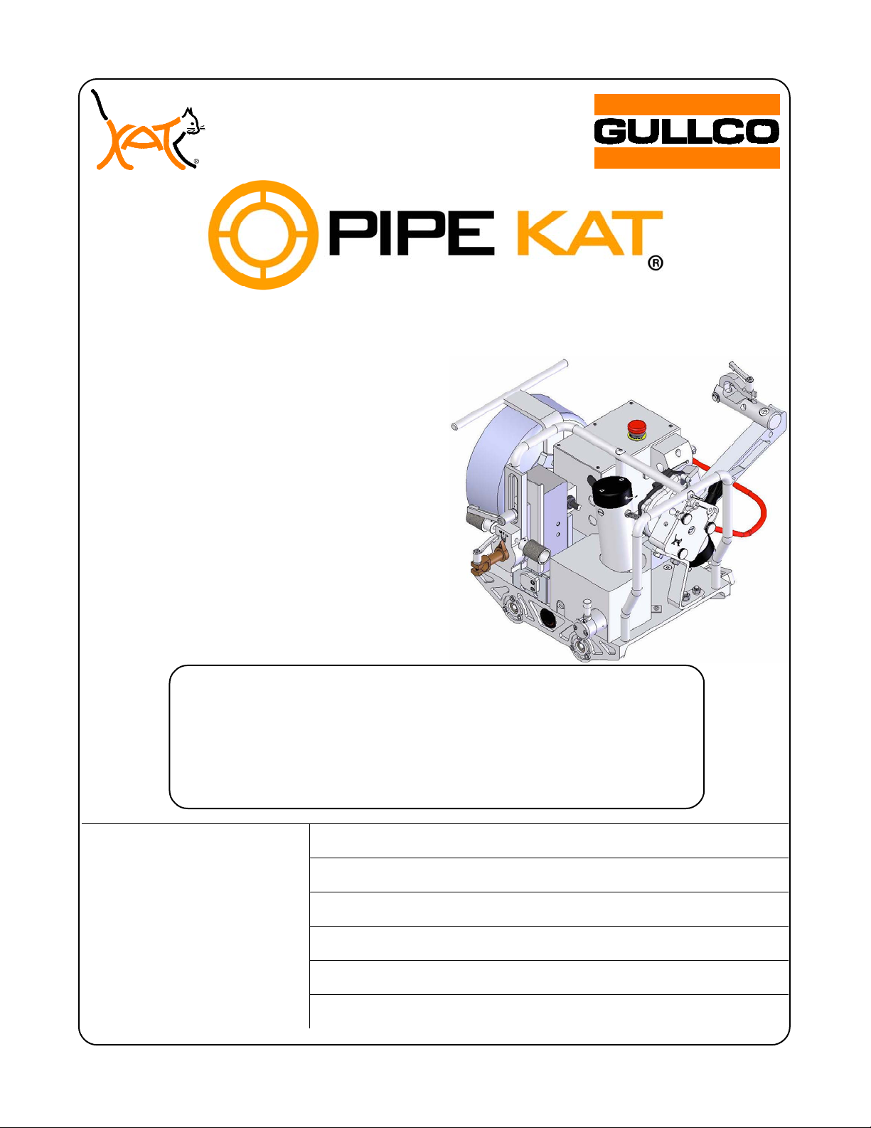
WELDING SYSTEM
LINEAR
OSCILLATOR
MODELS:
PK-500-LG-*
PK-500-LH-*
PK-500-LW-*
(*INDICATES VOLTAGE REFERENCE)
OPERATING
INSTRUCTIONS
Distributed by:
Phone: 905-953-4140 Fax: 905-953-4138 e-mail: sales@gullco.com
Phone: 440-439-8333 Fax: 440-439-3634 e-mail: ussales@gullco.com
Phone: +44 1257-253579 Fax: +44 1257-254629 e-mail:uksales@gullco.com
Phone: 61 (0) 7 3348-5515 Fax: 61 (0) 7 3348-5510 e-mail: ausales@gullco.com
Phone: 91-20-65260382 Fax: 91-20-26836656 e-mail: India.lo@gullco.com
GULLCO INTERNATIONAL LIMITED – CANADA
GULLCO INTERNATIONAL INC. – U.S.A.
GULLCO INTERNATIONAL [U.K.] LIMITED - EUROPE
GULLCO INTERNATIONAL PTY LIMITED - AUSTRALIA
GULLCO INTERNATIONAL INDIA PRIVATE LIMITED
GULLCO INTERNATIONAL SHANGHAI – LIMITED
Phone: +8621-50460341 Fax: +8621-50463554 e-mail: c.zhang@gullco.com
Website: www.gullco.com
Revised: June 3, 2013 GD-070


i


TABLE OF CONTENTS
SAFETY INSTRUCTIONS ............................................................................................................................ 2
SAFETY PRECAUTIONS ............................................................................................................................. 3
PIPE KAT
SYSTEM COMPONENTS ......................................................................................................... 4
®
GENERAL DESCRIPTION ........................................................................................................................... 5
PIPE BAND ................................................................................................................................................... 6
PIPE BAND SIZING .................................................................................................................................. 6
MOUNTING PIPE BAND (TRACK) ON THE PIPE ................................................................................... 7
MOUNTING THE CARRIAGE ON THE PIPE BAND (TRACK) ............................................................... 8
CARRIAGE UMBILICAL .............................................................................................................................. 9
REMOTE PENDANT .................................................................................................................................. 11
PIPE KAT
CARRIAGE .............................................................................................................................. 13
®
MAIN CONTROL BOX OPERATION ......................................................................................................... 16
FRONT PANEL ....................................................................................................................................... 16
LEFT SIDE PANEL ............................................................................................................... .................. 17
RIGHT SIDE PANEL ............................................................................................................................... 18
CARRIAGE OSCILLATOR CONTROL ...................................................................................................... 19
OSCILLATOR CONTROL PROGRAMMING .......................................................................................... 20
GENERAL PROGRAMMING MODE ...................................................................................................... 22
ADVANCED PROGRAMMING MODE ................................................................................................... 25
PIPE KAT
OSCILLATOR CONTROL ERROR CODES ........................................................................ 27
®
OSCILLATOR CONTROL FACTORY DEFAULTS ................................................................................. 29
CARRIAGE CONTROL .............................................................................................................................. 30
CARRIAGE CONTROL PROGRAMMING .............................................................................................. 34
GENERAL PROGRAMMING MODE ...................................................................................................... 35
ADVANCED PROGRAMMING MODE ................................................................................................... 36
PIPE KAT
CARRIAGE CONTROL ERROR CODES ............................................................................ 39
®
CARRIAGE CONTROL FACTORY DEFAULTS ......................................................................................... 41
WELDING POWER SOURCE INTERFACE CONNECTION ..................................................................... 43
AUTOMATIC CYCLE OPERATION ........................................................................................................... 45
AUTOMATIC CYCLE SEQUENCE OF EVENTS....................................................................................... 46
GENERAL SPECIFICATIONS ................................................................................................................... 48
OPTIONAL EQUIPMENT ........................................................................................................................... 49
1

SAFETY INSTRUCTIONS
Although the PIPE KAT® is manufactured for safe and dependable operation, it is impossible to
anticipate those combinations of circumstances which could result in an accident. An operator
of the PIPE KAT
set-up and maintenance.
Read and understand the operation manual before operating or performing service of this
equipment. Become familiar with the machines operation, applications and limitations. Keep
the operation manual in a clean and readily available location.
This equipment is normally used to automate / semi-automate welding processes. These
processes usually have any combination of the following; bright and hot arcs, flying sparks,
fumes, ultraviolet and infrared radiated energy, hot work-pieces, compressed gases, etc. The
onus is on the operator of this equipment to know, understand and follow all the safety
precautions associated with the process being used.
is cautioned to always practice "Safety First" during each phase of operation,
®
A careless operator invites trouble, and failure to follow safety practices may cause serious
injury or even death. Important safety precautions are given in the following:
Electrical Shock Prevention
Do not use this equipment in damp or wet locations.
Do not expose this equipment to rain.
Never carry this equipment by the cables or pull the cables to disconnect
from the receptacle.
Keep all cables from heat, oil and sharp edges.
Inspect all cables periodically and replace if damaged.
Inspect the security of all cables periodically and repair if loose.
Disconnect the power cord when not in use.
Disconnect the power cord positively to prevent electrical shock before
repair and service of the equipment.
Bodily Injury Prevention
Do not wear loose clothing, jewelry and loose, long hair which may get
caught into automatic systems or moving parts.
Ensure that the Pipe Band/track is well secured when installed.
Keep lifting handles dry, clean and free from oil and grease.
Keep hands away from the underside of the PIPE KAT
carriage when
®
there is the slightest possibility of it moving.
Always wear protective gloves when handling the track, to prevent injury
from sharp edges.
2
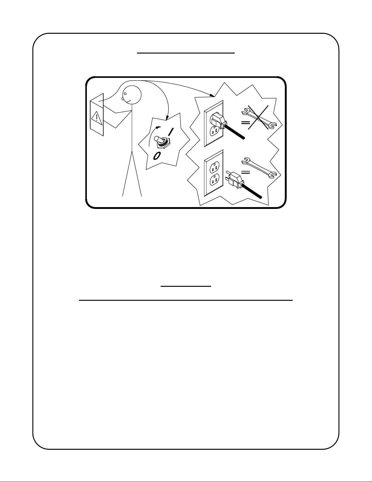
SAFETY PRECAUTIONS
The following cautionary/warning label is attached to each “PIPE KAT”® main control box
The above label pictorially represents the following:
“Warning:Read the manual before turning the unit on and before performing service.
Also, positively disconnect the unit from all power supplies before
servicing!”
IMPORTANT
READ THIS BEFORE OPERATING THE PIPE KAT® CARRIAGE
WARNING! Always turn the main power off before connecting/disconnecting any cables
to/from the PIPE KAT
result in control damage.
Do not cycle the power on and off in quick succession to the PIPE KAT
have diverse affects.
Ensure that an adequate and well-maintained weld return path is provided with good electrical
contact. Failure to do so may result in the welding current passing through the carriage and
damaging the wiring and electrical components.
carriage and main control box. Failure to comply may
®
system, as this may
®
ALL THE SAFE PRACTICES AND PRECAUTIONS MAY NOT BE GIVEN IN WRITING.
SOME ARE BASED ON COMMON SENSE, BUT OTHERS MAY REQUIRE TECHNICAL
BACKGROUND TO EXPLAIN.
3
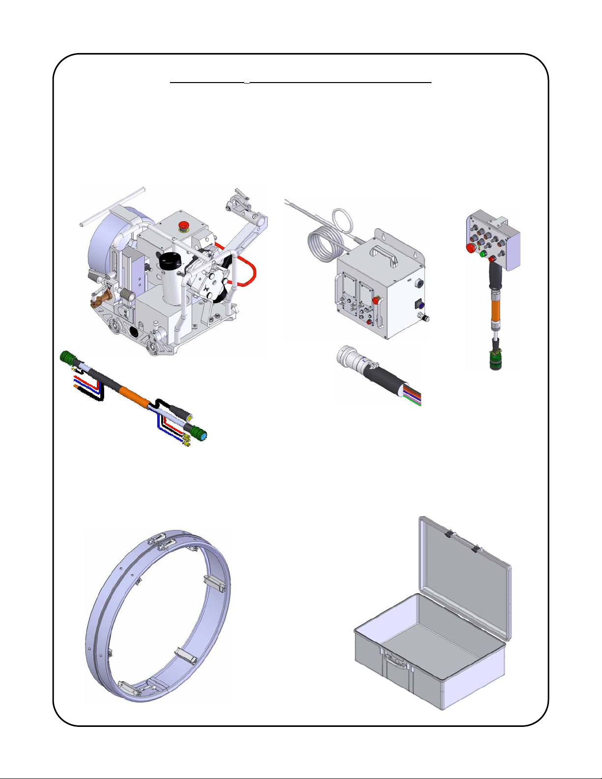
THE PIPE KAT® WELDING SYSTEM COMPONENTS
This manual covers the operation instructions of the following PIPE KAT® systems
PK-500-LG-*, PK-500-LH-*, PK-500-LW-* (* indicates input voltage: “A”=42 VAC; “B” =115
VAC; “C”= 230 VAC).
PIPE KAT
CARRIAGE PIPE KAT® MAIN CONTROL PIPE KAT®
®
WITH UMBILICAL WITH WELDING POWER SOURCE REMOTE
INTERFACE CABLE ASSEMBLY PENDANT
PIPE KAT
PIPE BAND STORAGE / TRANSPORTATION CASES
®
4

GENERAL DESCRIPTION
The PIPE KAT
is an advanced portable travel carriage designed for orbital welding. It is
®
an electrically powered track guided carriage that travels in forward and reverse directions at
precisely controlled speeds. It consists of 24 VDC permanent magnet gear motor which
engages the aluminum pipe band (track) through the self-aligning wheel system. Pipe bands are
designed and manufactured to customer specific applications (pipe diameter). The band is
typically constructed from extruded aluminum which insures a long life and durability in harsh
conditions.
The onboard wire feeder and wire spool holder is driven by a 24 VDC motor which feeds
wire to the welding torch at precisely controlled speeds. The wire spool holder accepts standard
8” / 10 lbs [20.3cm/4.54kgs] spools.
The Gullco Linear Oscillator is a compact, light weight, yet durable, reciprocating device
with a high torque, high resolution and low vibration stepper motor. It imparts a linear motion to
the weld gun. The low voltage Oscillator control provides a large, easy to read, multi-page
graphical display and offers programmable and electronic adjustment over the following
functions.
Oscillation width
Oscillation speed
Independent left and right dwells
Oscillation centre positioning (steering)
Multiple oscillation program storage
The precise control of these features enables accurate and repetitive weld oscillation.
The Gullco Carriage control provides control and adjustment over vertical slide, wire
feeder and carriage drive motor.
A motorized torch slide provides 2” or 50mm of tip-to-work distance adjustment, this serves as a
fine adjustment to control and maintain the proper torch to pipe height during setup and welding.
This motorized torch slide is connected to the linear oscillator by an adjustable radial Lead &
Lag mounting bracket
The versatile torch mounting bracketry provides a greater variation of torch mounting/positioning
flexibility.
INTENDED / FORESEEN USAGE
The Gullco PIPE KAT
is intended to automate and improve the quality of the welding
®
operation at precisely controlled speeds, along the Pipe Band as well as providing the interface
between the welding motion and the arc start and stop signals. The PIPE KAT
operates with
®
precise motion from start to finish regardless of the number of passes or the work pieces
involved, improving the quality, efficiency and repeatability of the process. Detrimental factors
such as poor or awkward accessibility, operator fatigue, or inconsistent workmanship are
eliminated. Required quality levels are consistently attained and productivity and profitability
increased.
5
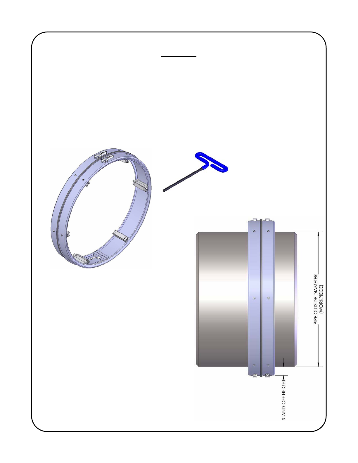
PIPE BAND
The Pipe Band is constructed from extruded aluminum and uses adjustable stand-offs
that serve as spacers to maintain the correct distance from the band to the pipe. The Pipe Band
utilizes a quick adjustment latches that allows the operator to mount and remove the band
easily. It is important that the Pipe Band is properly maintained and not subjected to any abuse
as it serves an important role in the carriages drive system. The operator must play close
attention to the condition of mating edge of the band that the PIPE KAT
carriage wheels run
®
on. Care must be taken to ensure that the band is kept clean from dirt and debris that could
damage the band. Also premature wear or damage to the band could result from improper
mounting of the PIPE KAT
carriage.
®
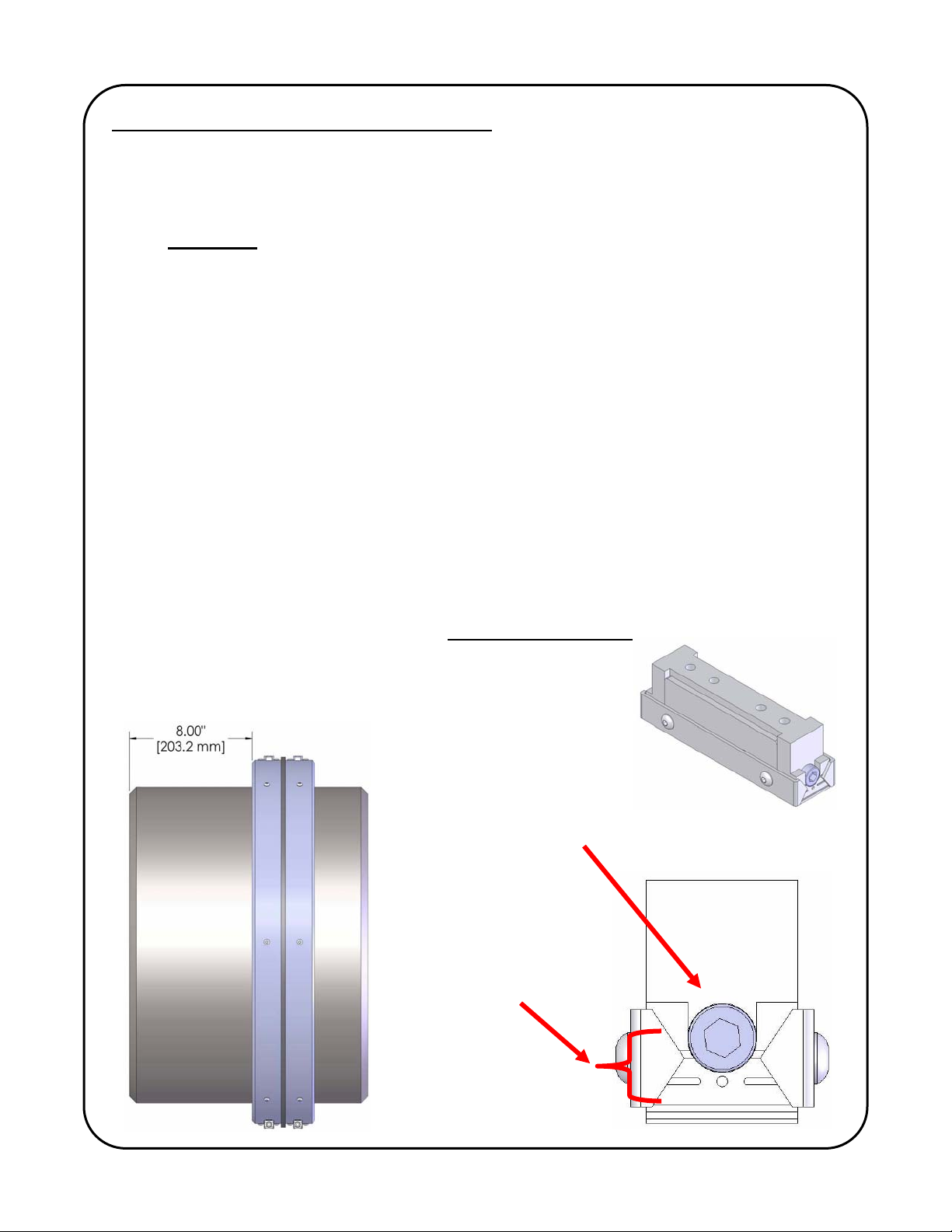
PIPE BAND SIZING
All Pipe Bands are manufactured to customer
specified pipe diameters & stand-off lengths.
The standard (minimum) stand-off height is 1.75”
[44.5mm]. Spacers can be used to increase the
height off the stand-offs.
The minimum spacer height can be used in
conjunction with standard stand-offs is 0.50”
[12.7mm]
6
MOUNTING PIPE BAND (TRACK) ON THE PIPE
1. Loosen latch screws on both top swing latches and bottom fixed latches. Do not remove
these screws.
2. Swing open the top pair of latches.
3. Separate or split the two bottom halves (fixed latches) of track away from each other.
Important ! The bottom halves must be a minimum of 3/16” [5mm] apart from each
other. This minimum distance will allow the track to safely open without causing
interference between the two track halves.
4. Place track on pipe by sliding over the end, or by opening the track to fit over the pipe
outside diameter.
5. Close latch over catch and tighten adjustment screw enough to allow the track to move,
but still remain on the pipe.
6. Align track to weld joint. The optimal distance is approximately 8.00” [203.2 mm]
between the inside edge of track and the center of the weld joint. NEVER use a hammer
or other such object to hit the Pipe Band into position, doing so will damage the edge
that the self-aligning wheels run on and result in poor performance.
7. Back off the adjustable standoffs on the pipe band. This is done by rotating the
adjustment screw counter clock-wise.
8. Finish tightening the top and bottom latch screws. The track must be sufficiently
fastened to remove any gaps between the ends of track at the joint. Do not over-tighten!
9. Verify track position on the pipe and then begin to tight each adjustable track standoff. It
is important that each standoff be adjusted by the same amount. By not doing this the
track will not be concentric with the pipe. See below for more details.
Track standoff assembly
Adjustment screw:
-Counter clock-wise to loosen
-Clock-wise to tighten
Adjustable range of
track mounting pad.
+/-0.157” [4mm]
7
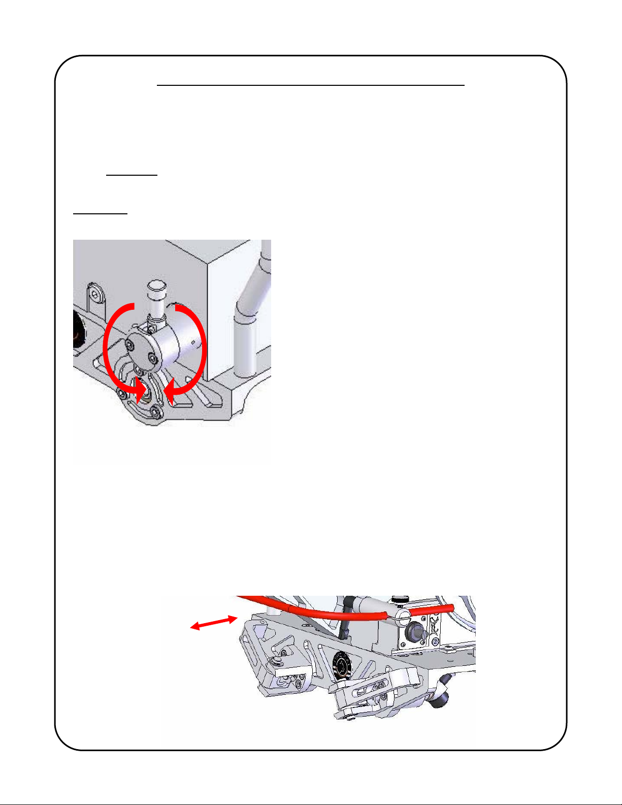
MOUNTING THE CARRIAGE ON THE PIPE BAND (TRACK)
The drive engagement lever (shown below) extends out the side of the carriage drive assembly
and allows the operator to engage or disengage the drive gear the rack on pipe band. The drive
gear can either be engaged or disengaged when mounting the carriage on the track. It also
permits free-wheeling for rapid positioning of the PIPE KAT
carriage. To engage the drive, pull
®
the lever away from the carriage body and turn in either direction until the lever arm is facing
down. Important: always make sure the drive is properly engaged by verifying the lever is
locked into position.
WARNING Never disengage the drive when there is a possibility that this action may result in
the equipment moving expectantly and causing injury.
MOUNTING PROCEDURE:
1) With both Carriage Locking Handles open, both handles have a built in detent to
hold them open, place the carriage directly over the Pipe Band/track.
2) Rest the carriage so that the top shoulder of all four wheel assemblies is resting
on the outer face of the band.
3) Close the locking handles securing the carriage to the track.
8
CARRIAGE UMBILICAL
The umbilical assembly provides communication between the Main Control Box and the
PIPE KAT
carriage, in addition to supplying cooling water, shielding gas and electrical welding
®
power to the torch.
The umbilical comprises of one control cable that provides power and communication to
the carriage, two water hoses (supply and return), shielding gas hose and welding electrode
cable. The umbilical is wrapped in a heat and abrasion resistant cover and uses a clamp to
secure the umbilical assembly to the carriage (see pages 13 & 14 to see where the umbilical
attaches to the PIPE KAT
carriage).
®
Note: It is important that the umbilical does not become tangled, coiled, or caught in
anyway that would impede the motion of the carriage and possibly damage electrical cables and
restrict water supply and/or shielding gas supply to the torch.
It is good practice to frequently inspect the carriage umbilical for damage and worn
components, any suspect parts should be replaced immediately to prevent further damage to
the PIPE KAT
system.
®
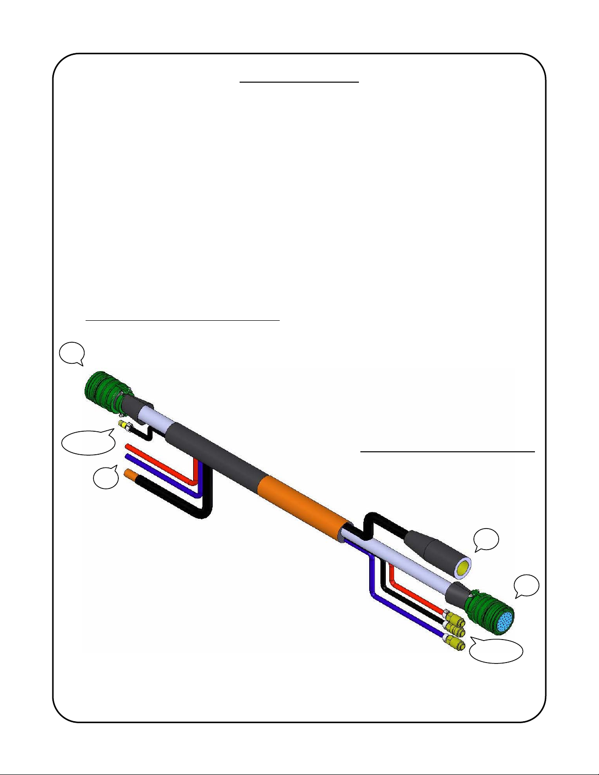
Connection to the Pipe KAT main control
3 & 4
Connection to the Pipe KAT carriage
3 & 4
9

Connection to the PIPE KAT
1) Additional 15 ft welding power supply electrode cable
2) One (1) large electrical connector for communication supply to the carriage
3) One (1) male plug for the shielding gas supply to the torch
4) Additional 15 ft of water cooling hoses (supply & return)
Connection to the PIPE KAT
1) One (1) twist connect welding power supply cable connection
2) One (1) large electrical connector for carriage communication
3) One (1) quick-disconnect fitting for the torch shielding gas
4) Two (2) quick-disconnect fittings cooling water, supply (blue) and return (red)
Main Control includes:
®
carriage includes:
®
10
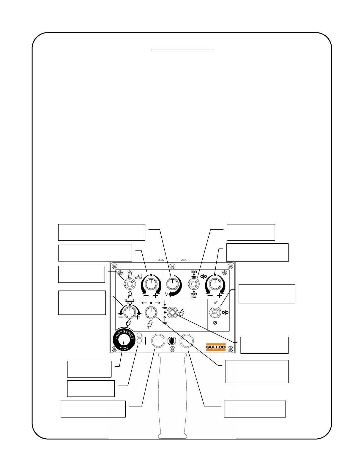
REMOTE PENDANT
The Remote pendant is used in conjunction with the main control to provide adjustment
during setup, initiate the weld cycle, provide fine adjustment during welding, and to stop the
weld cycle.
During setup the pendant is used to provide the following:
Position the carriage to the welding start position
Adjust oscillator center position
Adjust torch height in relation to the pipe
Advance the wire towards and back from the pipe
Set welding voltage
During the welding operation the pendant can be used to provide the following fine adjustments:
Carriage speed
Wire feed speed
The torch height in relation to the pipe (tip-to-work distance)
Oscillation center position
Oscillation width adjustment
Adjust welding voltage
The remote pendant is supplied with a 35ft communication cable that connects to the
right side panel of the PIPE KAT
Main Control. The functions of the Remote Pendant are
®
discussed in detail below.
WELDING VOLTAGE
CONTROL
WIRE FEED
JOG
CARRIAGE WELD SPEED
TRIM OVERRIDE
WIRE FEED SPEED
TRIM OVERRIDE
CARRIAGE
JOG
OSCILLATION
WIDTH
ADJUSTMENT
WELD ENABLED/
DISABLED
TORCH SLIDE
JOG
EMERGENCY
STOP
RED & GREEN
L.E.D.s
OSCILLATOR
CENTER POSITION
ADJUSTMENT
AUTO CYCLE START
PUSH BUTTON
AUTO CYCLE STOP
PUSH BUTTON
11

RED POWER LED: The red LED is illuminated to indicate there is power to the pendant. It also
flashes whenever there is an error code displayed on the controls.
WIRE FEED SPEED TRIM OVERRIDE: This speed adjustment knob allows for fine adjustment
in wire feed when the PIPE KAT
is in auto cycle mode (welding), this serves as a fine
®
adjustment to control and maintain the quality of the welding process. Adjustment range: +/- 19
inches/minute or +/- 48 cm/minute.
CARRIAGE WELD SPEED OVERRIDE: This speed adjustment knob allows for fine adjustment
in carriage weld speed when the PIPE KAT
is in auto cycle mode (welding), this serves as a
®
fine adjustment to control and maintain the quality of the welding process. Adjustment range: +/-
1.32 inches/minute or +/- 3.36 cm/minute.
WELDING VOLTAGE CONTROL: This adjustment knob allows for adjustment of the welding
voltage during setup or in auto mode. Note: welding voltage control is only available when the
PIPE KAT
is interfaced with the welding power source; see “Welding power source calibration”
®
on page 37 for more details.
WIRE FEED JOG: This 3-position momentary switch (Forward/Auto/Reverse) allows for
manual forward and reverse feeding of the welding wire when not in the auto cycle mode. The
switch is automatically disabled during the auto cycle.
CARRIAGE JOG: This 3-position momentary switch (Forward/Auto/Reverse) allows for manual
forward and reverse motion of the carriage when not in the auto cycle mode. Use the carriage
jog switch to establish the proper position of the carriage to the work prior to welding. When the
forward or reverse jog direction is selected, the carriage will travel at the set carriage (weld)
travel speed for three (3) seconds then it will progressively ramp up to maximum travel speed.
The switch is automatically disabled during the auto cycle.
EMERGENCY STOP: The emergency stop button serves as a safety feature that will terminate
all operations and shut down the PIPE KAT
unit when pressed. The emergency stop will
®
remain activated until it is reset by turning the button in a clock-wise motion. There are two (2)
other such emergency stop buttons; one (1) on the PIPE KAT
carriage assembly and one (1)
®
on the Main Control Box. These three (3) Emergency Stop buttons are wired in series, so any
one (1) will shut down the PIPE KAT
system when activated, and all three have to be released
®
in order for the system to power-up.
GREEN LED: The green LED is illuminated when the PIPE KAT
is operating in the auto cycle
®
mode.
AUTO CYCLE START PUSH BUTTON: This green button is used to initiate the auto cycle
mode. The button must be held for a minimum of two (2) seconds to reduce the possibility of
accidentally starting an automatic operation.
AUTO CYCLE STOP PUSH BUTTON: This red button is used to terminate the auto cycle
mode. The button must be held for a minimum of two (2) seconds to reduce the possibility of
accidentally aborting the automatic operation.
OSCILLATION WIDTH ADJUSTMENT: This adjustment knob allows the operator to adjust the
torch oscillation width while in the auto cycle mode (welding). This serves as a fine adjustment
12
to control and maintain the quality of the welding process. Width is increased or decreased in
0.01 Inch/CM increments.
OSCILLATION CENTER POSITION ADJUSTMENT: This adjustment knob allows the operator
to adjust the center position of the torch oscillation while in the auto cycle mode (welding) or to
jog the torch to the desired position prior to welding. This serves as a fine adjustment to control
and maintain the quality of the welding process. To make adjustments (steering) while welding,
rotate the knob in the appropriate direction until the center of the oscillation has moved to the
desired location. The size of these centre adjustment (steering) increments can be programmed
to be as large or small as preferred (see the “2
nd
Field” details on page 25).
TORCH SLIDE JOG: This 3-position momentary switch (In/Stop/Out) allows the operator to
adjust the In/Out distance of the torch relative to the work. The torch slide provides 2” or
[50.8mm] of motorized travel and can be used in both auto and manual modes. This serves as a
fine adjustment to control and maintain the tip-to-work distance. The linear speed of the slide
can be programmed through the Carriage Control (see page 36).
WELD ENABLED/DISABLED: This 2-position maintained switch allows the user to perform
simulated auto cycles, without actually welding, when in the Disable (
) position (i.e. when an
auto cycle is initiated the wire feeder, the welding power source, and the shielding gas flow are
disabled). When in the Enabled (
) position the auto cycle will perform a weld cycle (see page
45).
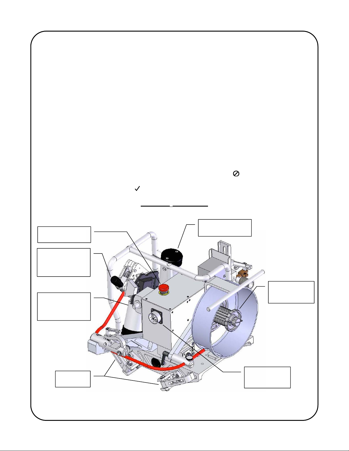
PIPE KAT
CARRIAGE
®
EMERGENCY
STOP
CARRIAGE DRIVE
MOTOR
WIRE FEED
PINCH ROLLER
PRESSURE
ADJUSTMENT
CARRIAGE
ELECTRODE
CABLE
CONNENCTION
WIRE SPOOL
TENSION
ADJUSTMENT
LOCKING
HANDLES
CARRIAGE
CONTROL
CONNECTION
13
 Loading...