

Gullco KR-200-L User Manual

“KAMEL”
(PIPE TURNING)
ROLLS
MODELS:
KR-200-L
KR-200-M
KR-750
PARTS LIST
&
OPERATING INSTRUCTIONS
Website: www.gullco.com
Distributed by:
Phone: 905-953-4140 Fax: 905-953-4138 e-mail: sales@gullco.com
Phone: 440-439-8333 Fax: 440-439-3634 e-mail: ussales@gullco.com
Phone: +44 1257-253579 Fax: +44 1257-254629 e-mail: sales@gullco.co.uk
Phone: 61 (0) 7 5439-0701 Fax: 61 (0) 7 5439-0704 e-mail: katoz@ozemail.com.au
Phone: 91-20-56260382 Fax: 91-20-26836656 e-mail: katindia@dataone.in
GULLCO INTERNATIONAL LIMITED – CANADA
GULLCO INTERNATIONAL INC. – U.S.A.
GULLCO INTERNATIONAL [U.K.] LIMITED - EUROPE
GULLCO INTERNATIONAL PTY LIMITED - AUSTRALIA
GULLCO INTERNATIONAL LIMITED – INDIA
GULLCO INTERNATIONAL SHANGHAI – LIMITED
Phone: +8621-50460341 Fax: +8621-50463554 e-mail: suntech@online.sh.cn
Revised: January 28, 2007 GD-045.DOC


SAFETY INSTRUCTIONS
Although the Gullco "Kamel" Turning Rolls and Idler Rolls are manufactured for safe and
dependable operation, it is impossible to anticipate those combinations of circumstances, which
could result in an accident. An operator of this equipment is cautioned to always practice "Safety
First" during each phase of operation, setup and maintenance.
Read and understand the whole operation manual (including the supplementary GSP-1000 control
manual, “GD-042”) before operating or performing service of this equipment. Become familiar with
the machines operation, applications and limitations. Keep the operation manual in a clean and
readily available location.
This equipment is normally used to automate / semi-automate welding or cutting processes. These
processes usually have any combination of the following; bright and hot arcs, flying sparks, fumes,
ultraviolet and infrared radiated energy, hot work-pieces, compressed gases, etc.. The onus is on
the operator of this equipment to know, understand and follow all the safety precautions associated
with the process being used.
A careless operator invites troubles, and failure to follow safety practices may cause serious injury
or even death. Important safety precautions are given in the following:
Electrical Shock Prevention
¾ Do not use this equipment in damp or wet locations.
¾ Do not expose this equipment to rain.
¾ Do not touch electrically live parts or electrode with skin or wet clothing.
¾ Insulate yourself from the work and ground.
¾ Never carry this equipment by the cables or pull the cables to disconnect from the
receptacle.
¾ Keep all cables from heat, oil and sharp edges.
¾ Inspect all cables periodically and replace if damaged.
¾ Inspect the security of all cables periodically and repair if loose.
¾ Disconnect the power cord when not in use.
¾ Disconnect the power cord positively
of the equipment.
to prevent electrical shock before repair and service
Bodily Injury Prevention
¾ Do not wear loose clothing, jewellery or loose, long hair, which may get caught into
automatic systems or moving parts.
¾ Keep equipment (especially lifting handles) dry, clean and free from oil & grease.
¾ Never set the "Kamel" roll to run unattended, as any misalignment between the turning roll
and idler roll(s) will result in the pipe being propelled along its axis of rotation and may fall of
the rolls.
¾ Keep hands away fro m the tired wheels and work-piece when it is in motion, or when there
is the slightest possibility of motion.
¾ Wherever possible, avoid mounting devices, etc., that protrude from the rotating mass, and
pose possible pinch-points.
¾ Make certain that work-piece protrusions will not strike the floor, roll frame, tired wheels or
other object during rotation. Be sure that the tired wheels have a smooth, unobstructed
clear path to roll on.
¾ There should only ever be one (1) operator working at the machine at any given time.
¾ Do not operate this equipment if drowsy from medication or fatigue.
¾ Only lift the machine using adopted safe lifting standards and practices.
1
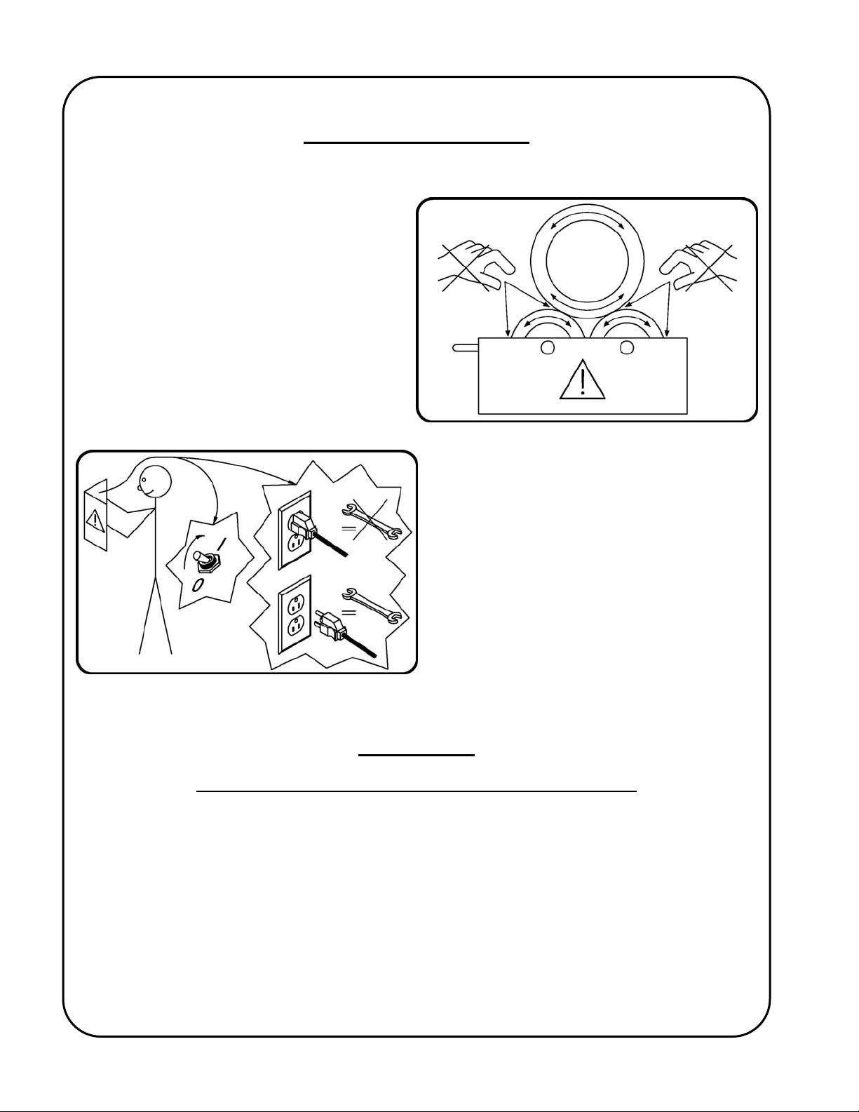
SAFETY PRECAUTIONS
The following cautionary/warning labels are attached to each "Kamel" roll:-
Warning:-
Never place your hands near these pinch
points when the rolls are turning, or when
there is a possibility of the rolls turning!
Warning:Read the manual before turning the unit on
and before performing service. Also,
positively disconnect the unit from all power
supplies before servicing!
IMPORTANT
READ THIS BEFORE OPERATING THE “KAMEL” ROLL
Important information regarding safety and operation of the “GSP-1000” motor control used in the
“Kamel” Roll, is contained in a supplemental manual attached at the end of this manual. It is
equally important to read, understand and apply the information contained within that manual. The
manual (GD-042) has a title “Technical Information For The Gullco “GSP-1000” Microprocessor
Based Motor Control”, and it’s pages are numbered with a prefix of “T-“.
ALL THE SAFE PRACTICES AND PRECAUTIONS MAY NOT BE GIVEN IN WRITING. SOME
ARE BASED ON COMMON SENSE, BUT OTHERS MAY REQUIRE TECHNICAL
BACKGROUND TO EXPLAIN.
2
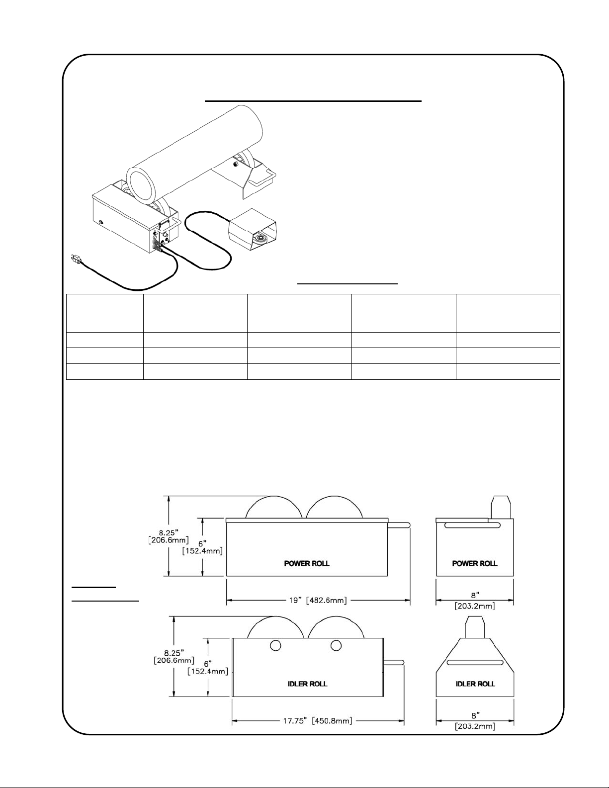
"KAMEL" PIPE TURNING ROLLS
This parts list covers the operation and
maintenance requirements of the following
Gullco "Kamel" pipe turning rolls;
KR-200-L
KR-200-M
KR-750
SPECIFICATIONS
1 - 35.4 IPM
Standard Power
Model
KR-200-L
KR-200-M
KR-750
Turning capacity: KR-200-L = 1500 Lbs. [680 Kg.] KR-200-M = 1000 Lbs. [454 Kg.]
Load capacity / roll: 750 Lbs. [340 Kg.]
Pipe diameter capacity: 2" to 16" [51 - 406 mm]
Power roll weight: 48 Lbs. [21.8 Kg.]
Idler roll weight: 16 Lbs. [7.3 Kg.]
Supply Voltage: Either 42, 115 or 230 VAC, single phase, 50/60 Hz., 200 watts.
Drive motor: 24 VDC permanent magnet gear motor.
Complies with: C.S.A. and NRTL/C and C.E. regulations.
Roll
9 9
9 9
[2.5–89.9 CM/MIN]
Rotary Speed
2.2 – 70.8 IPM
[5.6–180 CM/MIN]
Rotary Speed Idler Roll
9
General
Dimensions
3

GENERAL DESCRIPTION
The Gullco "Kamel", power turning rolls are electrically powered units that use wheels to rotate (roll)
pipe. They are designed to be used in conjunction with a non-powered idler roll / rolls. Each of the
wheels of the turning, and idler, rolls have a moulded rubber tread and rotate on anti-friction roller
bearings. The turning roll uses these wheels to provide friction drive and uniformly smooth pipe
rotation, while the idler roll / rolls use these wheels to support the pipe.
The powered turning roll imparts tractive effort to the wheels by having a knurled drive wheel press
against each of the rubber wheels. This knurled drive wheel is directly attached to the output shaft
of a 24 VDC, permanent magnet motor and gear head power unit assembly. The microprocessor
motor control offers operator interface of forward, stop, reverse and infinitely variable control of the
speed, within the range of the model. Safety is greatly enhanced by the use of Gullco’s low voltage
(24 V), control and power supply system that is available in one of the following three line voltage
inputs: 42, 115 and 230 VAC, single phase, 50/60 Hz, or any unregulated 24 VDC power supply at
220 watts of power. The motor control offers operator interface of run/stop, clockwise, neutral and
counter-clockwise rotation as well as speed regulation. A power supply on/off isolation switch is
also provided. The rotation speed is electronically controlled using an optical tachometer located
on the back of the gear-motor and is infinitely variable in both clockwise and counter-clockwise
directions, within the range of the model, by a rotary speed adjustment potentiometer located on the
faceplate of the "Kamel" power roll. The powered turning roll is also equipped with a 7-1/2 foot [2.3
mtr.] long power cable and a remote foot switch on 10 feet [3 mtr.] of cable. A lifting handle is also
provided for portability.
INTENDED / FORESEEN USAGE
Gullco "Kamel" turning rolls are widely applied to reduce the cost of welding and cutting pipes,
flanges and fittings. They are compact, portable and provide fast positioning and smooth rotation.
The power turning roll requires at least one or more idler rolls to support the work piece. Both the
power and idler roll are designed to support 750 Lbs. [340 Kg.]. Therefore, by using one powered
turning roll and one idler roll a maximum weight of 1500 Lbs. [680 Kg.] is capable of being
supported.
Through automation / semi automation, the quality, efficiency and repeatability of the weld or cut
produced is greatly improved. Detrimental factors such as poor or awkward accessibility, operator
fatigue, or inconsistent workmanship are eliminated. Required quality levels are consistently
attained and productivity and profitability increased.
4

5
INSTALLATION
ELECTRICAL CONNECTION
WARNING! Ensure proper AC earth grounding of the Gullco "Kamel" power turning roll and all
auxiliary equipment (where applicable), before applying power. Failure to do so may
invalidate the Gullco Warranty.
WARNING! Before connecting the power turning roll to a power source (receptacle, outlet, etc.,)
be sure that the voltage supplied is the same as that specified on the nameplate of
the turning roll. If in doubt, DO NOT PLUG IN THE "KAMEL" ROLL. Copies of the
possible nameplates are shown below:
As the colours of the wires in the mains lead of this equipment may not correspond with the
coloured markings identifying the terminals in your plug, proceed as follows:
− The Green & Yellow or Green wire must be connected to the terminal in the plug which is
allocated for “Earth” / “Ground”.
− The Blue or White wire must be connected to the terminal that is allocated for “Neutral”.
− The Brown or Black wire must be connected to the terminal that is allocated for “Live”.
230V Equipment must be installed in accordance with CEC, NEC or other applicable electrical
code.
MECHANICAL INSTALLATION
WARNING! Check to ensure that no parts have become loose during transportation.
All "Kamel" powered turning rolls are shipped from the factory completely assembled. The only
work necessary to make the unit operational is to connect electrical power, as described previously.
When setting up power and idler rolls it is good practice to align the rolls accurately. The rolls
should all be parallel and at the same elevation, with the wheels in line. It is recommended that
they be rested on a smooth, flat surface.
6
OPERATION
Through the use of the optical tachometer closed loop feedback circuitry, the motor control can
obtain constant speed control of the powered turning rolls. The motor and the control operate on
24VDC, supplied by a power supply located behind the control panel assembly. Therefore, all
operator interface devices (except the power on/off switch) are subjected to signal level voltages
only.
The power On/Off switch is used to disconnect the power to the rest of the control circuitry.
I = On, O = Off.
WARNING! The motor control must not be continually started and stopped by the removal and
reapplying of power to the control. Turning the power off to the control will not
provide instant braking and continued use will damage the control. Allow ten (10)
seconds after the removal of power before reapplying the power to the motor control.
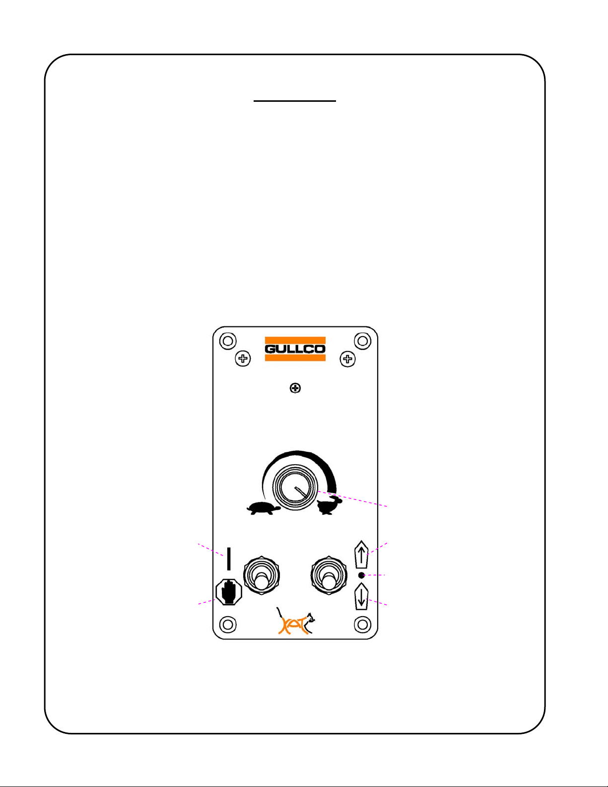
The following provides a brief description of the GSP-1000 control (refer to the sketch below):
Speed Adjustment
Counter-Clockwise = Slower
Clockwise = Faster
Control in Run Mode
Control in Hold (Stop) Mode
Command Forward Motion
Neutral
Command Reverse Motion
The Run/Stop Switch
¾ This switch is used in conjunction with the footswitch to start and stop rotation of the
“Kamel” roll.

7
The Forward/Neutral/Reverse Switch
¾ This is used to select the direction of rotation.
The Speed Adjustment Knob
¾ This adjustment is used to increase (clockwise) or decrease (counter-clockwise) the
rotational speed of the “Kamel” roll.
WARNING! Avoid changing the direction of rotation without making sure that rotation comes to a
complete stop first. Failure to comply may cause an overload.
WARNING! Avoid repeatedly starting and stopping the “Kamel” roll in quick, short succession, as
this will reduce the life expectancy of the control and the motor.
The remote foot switch is used to start and stop rotation of the rubber wheels. Depressing the foot
switch will activate rotation and releasing the foot switch will deactivate the rotation and apply
braking. The Run/Stop switch must be in the Run position and a rotation direction must be selected
for the unit to operate when the footswitch is depressed.
Notes:
If the optional GP-200-023, Forward/Stop/Reverse Footswitch assembly is installed (instead of the
standard Run/Stop footswitch), the footswitch will start and stop the rotation as previously described, and
allow the operator to choose which direction the rolls will rotate. The Run/Stop switch must be in the Run
position and the Forward/Neutral/Reverse switch must be in the Neutral position for the unit to operate
when the footswitch is depressed.
If the optional GP-200-025, Variable Speed Footswitch assembly is installed (instead of the standard
Run/Stop footswitch), the footswitch will start and stop the rotation and depending on the varying amount
that the footswitch is depressed, will vary the rotational speed from zero (0) rpm up to the speed
regulated by the Speed Adjustment Knob of the GSP control. I.e. if the GSP-1000 Speed Adjustment
Knob is set to 30% of full speed range, then the Variable Speed Footswitch will be able to vary the
“Kamel” roll speed between 0 and 30%. The Run/Stop switch must be in the Run position and a rotation
direction must be selected for the unit to operate when the footswitch is depressed.
The fuse holder allows accessibility to the main fuse by pushing the cap in towards the main body
and twisting in a counterclockwise direction.

8
LOADING
WARNING! Lower work-pieces onto the rolls gently. DO NOT DROP WORK-PIECES ONTO
THE ROLLS. Impact and shock loads are many times greater than the "dead-
weight” of the work-piece. Dropping loads onto the rolls can result in damage!
If more than one idler roll is to be used, be sure that the work-piece touches all wheels that are
intended for support. Ensure that the work-piece rests on the full face-width of the wheels to avoid
damage.
If one end of the work-piece is heavier than the other, be sure that the roll supporting the heavier
end is not being overloaded in weight capacity.
Capacities of turning rolls are stipulated to turn cylindrical, concentric work-pieces. If your workpiece has any eccentric loads at all, be sure to check carefully to avoid overloading the drive. Even
small eccentric loads can quickly overload the drive. Overloading the rolls, either by weight or
eccentricity, could cause the wheels to stall. Under this condition the knurled drive wheel could
continue to rotate and act as a milling cutter on the outside diameter of the rubber wheels.
Wherever possible, counter weights should be used to balance eccentric loads. Take into
consideration the additional weight and distribution of the counterbalance.
Attention should be given to the proximity of the rubber wheels with respect to heat zones through
preheating, cutting, etc..
MAINTENANCE
The Gullco "Kamel", power turning rolls and idler rolls are heavy duty, robust pieces of equipment,
and under normal conditions, they will give you years of trouble free service, if they are operated
within the limits of their expected use and if the following maintenance points are adhered to:
Clean all excess dust, spatter, slag etc. from the rolls regularly. Do not allow any foreign material to
impede operation.
Periodically check the power roll for tension of the drive system. Positively disconnect the power
cord from the power source before attempting service. To test the tension of the drive system,
attempt to turn one wheel at a time by hand. If it takes reasonable force in order to make each
wheel slip, then the tension is set correctly. If one or both wheels slip with ease, then adjustment is
required. To adjust the drive tension, loosen the lock nut (item # 42 - drawing # KR-200) that
secures the motor mounting plate. Then by sliding the motor mounting plate (item # 47 - drawing #
KR-200) along the length of the “Kamel” roll and tightening the adjusting bolt (item # 38 - drawing #
KR-200), the knurled drive wheel can be positioned so that it is applying a snug pressure equally to
both rubber wheels. The lock nut (item # 42) can then be retightened. Test, once again, that the
tension is set correctly. Do not tighten the tensioning system any more than necessary.
Excessive pressure could cause damage to the output shaft of the drive motor as well as tearing
the rubber treads of the wheels. Do not attempt to compensate for a "Gouged Tire" by increasing
the drive pressure; instead replace the wheel with an undamaged one.
Every two hundred and forty (240) hours, the wheels should be lubricated with a general purpose,
light duty grease. A grease nipple is provided in the side of each wheel.
 Loading...