

Page 1
GUILD
130W 218 Piece Rotary Tool Kit
Instruction Manual
PDM130DC.1
After Sales Support
UK/Ireland 0333 3201989
Help@guildpowertools.co.uk
Important - Please read these instructions fully before operating or maintaining your Guild mini drill
These instructions contain important information that will help you get the best from your Guild
mini drill, ensuring it remains safe to operate.
If you need help or have damaged or missing parts, call the Customer Helpline on 0333 3201989
Page 2

Contents
Safety Information.....................................................................................................3
In The Box.................................................................................................................10
Accessories..............................................................................................................10
Operating Instructions.............................................................................................12
Using Accessories....................................................................................................17
Maintenance..............................................................................................................18
Trouble Shooting.......................................................................................................18
Technical Data..........................................................................................................19
Environmental Protection........................................................................................21
Guarantee................................................................................................................21
Declaration of Conformity........................................................................................21
Plug Replacement(UK & Ireland Only).....................................................................22
2
Customer Helpline 0333 3201989
Page 3

Safety Information
Important - Please read these instructions fully before starting assembly
Warning Symbols
The following warning symbols appear throughout this assembly manual and
indicate the appropriate safety measures you should take when assembling and
operating the mini drill.
To reduce the risk of injury, Please read the instruction manual
Warning
Wear ear protection
Wear eye protection
Wear dust mask
Double insulation
Waste electrical products must not be disposed of with household waste. Please recycle
where facilities exist. Check with your local authorities or retailer for recycling advice.
Customer Helpline 0333 3201989
3
Page 4

Safety Information
Important - Please read these instructions fully before starting assembly
General Power Tool Safety Warnings
WARNING! Read all safety warnings and all instructions. Failure to follow the
warnings and instructions may result in electric shock, fire and/or serious injury.
Save all warnings and instructions for future reference.
The term “power tool” in the warnings refers to your mains-operated (corded) power tool
or battery-operated (cordless) power tool.
1) Work area safety
a) Keep work area clean and well lit. Cluttered or dark areas invite accidents.
b) Do not operate power tools in explosive atmospheres, such as in the presence of
flammable liquids, gases or dust. Power tools create sparks which may ignite the
dust or fumes.
c) Keep children and bystanders away while operating a power tool. Distractions can
cause you to lose control.
2) Electrical safety
a) Power tool plugs must match the outlet. Never modify the plug in any way. Do not
use any adapter plugs with earthed (grounded) power tools. Unmodified plugs and
matching outlets will reduce risk of electric shock.
b) Avoid body contact with earthed or grounded surfaces, such as pipes, radiators,
ranges and refrigerators. There is an increased risk of electric shock if your body is
earthed or grounded.
c) Do not expose power tools to rain or wet conditions. Water entering a power tool will
increase the risk of electric shock.
d) Do not abuse the cord. Never use the cord for carrying, pulling or unplugging the
power tool. Keep cord away from heat, oil, sharp edges or moving parts. Damaged or
entangled cords increase the risk of electric shock.
e) When operating a power tool outdoors, use an extension cord suitable for outdoor
use. Use of a cord suitable for outdoor use reduces the risk of electric shock.
f) If operating a power tool in a damp location is unavoidable, use a residual
current device (RCD) protected supply. Use of an RCD reduces the risk of electric
shock.
3) Personal safety
a) Stay alert, watch what you are doing and use common sense when operating a
power tool. Do not use a power tool while you are tired or under the influence of
drugs, alcohol or medication. A moment of inattention while operating power tools
may result in serious personal injury.
b) Use personal protective equipment. Always wear eye protection. Protective
equipment such as dust mask, non-skid safety shoes, hard hat, or hearing protection
used for appropriate conditions will reduce personal injuries.
c) Prevent unintentional starting. Ensure the switch is in the off-position before
connecting to power source and/or battery pack, picking up or carrying the tool.
Carrying power tools with your finger on the switch or energising power tools that
have the switch on invites accidents.
d) Remove any adjusting key or wrench before turning the power tool on. A wrench or a
4
Customer Helpline 0333 3201989
Original Instructions
Page 5

Safety Information
Important - Please read these instructions fully before starting assembly
General Power Tool Safety Warnings
key left attached to a rotating part of the power tool may result in personal injury.
e) Do not overreach. Keep proper footing and balance at all times. This enables better
control of the power tool in unexpected situations.
f) Dress properly. Do not wear loose clothing or jewellery. Keep your hair, clothing
and gloves away from moving parts. Loose clothes, jewellery or long hair can be
caught in moving parts.
g) If devices are provided for the connection of dust extraction and collection facilities,
ensure these are connected and properly used. Use of dust collection can reduce
dust-related hazards.
4) Power tool use and care
a) Do not force the power tool. Use the correct power tool for your application.
The correct power tool will do the job better and safer at the rate for which it was
designed.
b) Do not use the power tool if the switch does not turn it on and off. Any power tool
that cannot be controlled with the switch is dangerous and must be repaired.
c) Disconnect the plug from the power source and/or the battery pack from the power
tool before making any adjustments, changing accessories, or storing power
tools. Such preventive safety measures reduce the risk of starting the power tool
accidentally.
d) Store idle power tools out of the reach of children and do not allow persons
unfamiliar with the power tool or these instructions to operate the power tool.
Power tools are dangerous in the hands of untrained users.
e) Maintain power tools. Check for misalignment or binding of moving parts, breakage
of parts and any other condition that may affect the power tool’s operation. If
damaged, have the power tool repaired before use. Many accidents are caused by
poorly maintained power tools.
f) Keep cutting tools sharp and clean. Properly maintained cutting tools with sharp
cutting edges are less likely to bind and are easier to control.
g) Use the power tool, accessories and tool bits etc. in accordance with these
instructions, taking into account the working conditions and the work to be
performed. Use of the power tool for operations different from those intended could
result in a hazardous situation.
5) Service
a) Have your power tool serviced by a qualified repair person using only identical
replacement parts. This will ensure that the safety of the power tool is maintained.
Customer Helpline 0333 3201989
5
Page 6

Safety Information
Important - Please read these instructions fully before starting assembly
Safety instructions for all operations
Safety Warnings common for grinding, sanding, wire brushing, polishing, carving or
abrasive cutting-off operations:
a) This power tool is intended to function as a grinder, sander, wire brush, polisher,
carving or cut-off tool. Read all safety warnings, instructions, illustrations and
specifications provided with this power tool. Failure to follow all instructions listed
below may result in electric shock, fire and/or serious injury.
b) Do not use accessories which are not specifically designed and recommended by the
tool manufacturer. Just because the accessory can be attached to your power tool, it
does not assure safe operation.
c) The rated speed of the grinding accessories must be at least equal to the maximum
speed marked on the power tool. Grinding accessories running faster than their rated
speed can break and fly apart.
d) The outside diameter and the thickness of your accessory must be within the capacity
rating of your power tool. Incorrectly sized accessories cannot be adequately controlled.
e) The arbour size of wheels, sanding drums or any other accessory must properly fit
the spindle or collet of the power tool. Accessories that do not match the mounting
hardware of the power tool will run out of balance, vibrate excessively and may cause
loss of control.
f) Mandrel mounted wheels, sanding drums, cutters or other accessories must be
fully inserted into the collet or chuck. If the mandrel is insufficiently held and/or
the overhang of the wheel is too long, the mounted wheel may become loose and be
ejected at high velocity.
g) Do not use a damaged accessory. Before each use inspect the accessory such as
abrasive wheels for chips and cracks, sanding drum for cracks, tear or excess wear,
wire brush for loose or cracked wires. If power tool or accessory is dropped, inspect
for damage or install an undamaged accessory. After inspecting and installing an
accessory, position yourself and bystanders away from the plane of the rotating
accessory and run the power tool at maximum no-load speed for one minute.
Damaged accessories will normally break apart during this test time.
h) Wear personal protective equipment. Depending on application, use face shield,
safety goggles or safety glasses. As appropriate, wear dust mask, hearing
protectors, gloves and workshop apron capable of stopping small abrasive or
workpiece fragments. The eye protection must be capable of stopping flying debris
generated by various operations . The dust mask or respirator must be capable of
filtrating particles generated by your operation. Prolonged exposure to high intensity
noise may cause hearing loss.
i) Keep bystanders a safe distance away from work area. Anyone entering the work
area must wear personal protective equipment. Fragments of workpiece or of a
broken accessory may fly away and cause injury beyond immediate area of operation.
j) Hold power tool by insulated gripping surfaces only, when performing an operation
where the cutting accessory may contact hidden wiring or its own cord. Cutting
accessory contacting a “live” wire may make exposed metal parts of the power tool
“live” and could give the operator an electric shock.
k) Always hold the tool firmly in your hand(s) during the start-up. The reaction torque of
the motor, as it accelerates to full speed, can cause the tool to twist.
l) Use clamps to support workpiece whenever practical. Never hold a small workpiece
6
Customer Helpline 0333 3201989
Page 7

Safety Information
Important - Please read these instructions fully before starting assembly
Safety Warnings for battery pack
in one hand and the tool in the other hand while in use. Clamping a small workpiece
allows you to use your hand(s) to control the tool. Round material such as dowel rods,
pipes or tubing have a tendency to roll while being cut, and may cause the bit to bind or
jump toward you.
m) Position the cord clear of the spinning accessory. If you lose control, the cord may be
cut or snagged and your hand or arm may be pulled into the spinning accessory.
n) Never lay the power tool down until the accessory has come to a complete stop. The
spinning accessory may grab the surface and pull the power tool out of your control.
o) After changing the bits or making any adjustments, make sure the collet nut, chuck
or any other adjustment devices are securely tightened. Loose adjustment devices
can unexpectedly shift, causing loss of control, loose rotating components will be
violently thrown.
p) Do not run the power tool while carrying it at your side. Accidental contact with the
spinning accessory could snag your clothing, pulling the accessory into your body.
q) Regularly clean the power tool’s air vents. The motor’s fan will draw the dust inside
the housing and excessive accumulation of powdered metal may cause electrical
hazards.
r) Do not operate the power tool near flammable materials. Sparks could ignite these
materials.
s) Do not use accessories that require liquid coolants. Using water or other liquid
coolants may result in electrocution or shock.
Further safety instructions for all operations
Kickback and related warnings
Kickback is a sudden reaction to a pinched or snagged rotating wheel, sanding band, brush
or any other accessory. Pinching or snagging causes rapid stalling of the rotating accessory
which in turn causes the uncontrolled power tool to be forced in the direction opposite of the
accessory’s rotation.
For example, if an abrasive wheel is snagged or pinched by the workpiece, the edge of the
wheel that is entering into the pinch point can dig into the surface of the material causing
the wheel to climb out or kick out. The wheel may either jump toward or away from the
operator, depending on direction of the wheel’s movement at the point of pinching. Abrasive
wheels may also break under these conditions.
Kickback is the result of power tool misuse and/or incorrect operating procedures or
conditions and can be avoided by taking proper precautions as given below.
a) Maintain a firm grip on the power tool and position your body and arm to allow you to
resist kickback forces. The operator can control kickback forces, if proper precautions
are taken.
b) Use special care when working corners, sharp edges etc. Avoid bouncing and
snagging the accessory. Corners, sharp edges or bouncing have a tendency to snag
the rotating accessory and cause loss of control or kickback.
c) Do not attach a toothed saw blade. Such blades create frequent kickback and loss of
control.
d) Always feed the bit into the material in the same direction as the cutting edge is
exiting from the material (which is the same direction as the chips are thrown).
Customer Helpline 0333 3201989
7
Page 8

Safety Information
Important - Please read these instructions fully before starting assembly
Further safety instructions for all operations
Feeding the tool in the wrong direction causes the cutting edge of the bit to climb out
of the work and pull the tool in the direction of this feed.
e) When using rotary files, cut-off wheels, high-speed cutters or tungsten carbide
cutters, always have the work securely clamped. These wheels will grab if they
become slightly canted in the groove, and can kickback. When a cut-off wheel grabs,
the wheel itself usually breaks. When a rotary file, high-speed cutter or tungsten
carbide cutter grabs, it may jump from the groove and you could lose control of the
tool.
Safety Warnings Specific for Grinding and Abrasive Cutting-Off Operations:
a) Use only wheel types that are recommended for your power tool and only for
recommended applications. For example: do not grind with the side of a cut-off
wheel. Abrasive cut-off wheels are intended for peripheral grinding, side forces
applied to these wheels may cause them to shatter.
b) For threaded abrasive cones and plugs use only undamaged wheel mandrels with an
unrelieved shoulder flange that are of correct size and length. Proper mandrels will
reduce the possibility of breakage.
c) Do not “jam” a cut-off wheel or apply excessive pressure. Do not attempt to make
an excessive depth of cut. Overstressing the wheel increases the loading and
susceptibility to twisting or snagging of the wheel in the cut and the possibility of
kickback or wheel breakage.
d) Do not position your hand in line with and behind the rotating wheel. When the
wheel, at the point of operation, is moving away from your hand, the possible kickback
may propel the spinning wheel and the power tool directly at you.
e) When wheel is pinched, snagged or when interrupting a cut for any reason, switch
off the power tool and hold the power tool motionless until the wheel comes to a
complete stop. Never attempt to remove the cut-off wheel from the cut while the
wheel is in motion otherwise kickback may occur. Investigate and take corrective
action to eliminate the cause of wheel pinching or snagging.
f) Do not restart the cutting operation in the workpiece. Let the wheel reach full speed
and carefully re-enter the cut. The wheel may bind, walk up or kickback if the power
tool is restarted in the workpiece.
g) Support panels or any oversized workpiece to minimize the risk of wheel pinching
and kickback. Large workpieces tend to sag under their own weight. Supports must be
placed under the workpiece near the line of cut and near the edge of the workpiece on
both sides of the wheel.
h) Use extra caution when making a “pocket cut” into existing walls or other blind
areas. The protruding wheel may cut gas or water pipes, electrical wiring or objects
that can cause kickback.
8
Customer Helpline 0333 3201989
Page 9

Safety Information
Important - Please read these instructions fully before starting assembly
Safety Warnings Specific for Wire Brushing Operations
a) Be aware that wire bristles are thrown by the brush even during ordinary operation.
Do not overstress the wires by applying excessive load to the brush. The wire bristles
can easily penetrate light clothing and/or skin.
b) Allow brushes to run at operating speed for at least one minute before using them.
During this time no one is to stand in front or in line with the brush. Loose bristles or
wires will be discharged during the run-in time.
c) Direct the discharge of the spinning wire brush away from you. Small particles and
tiny wire fragments may be discharged at high velocity during the use of these brushes
and may become imbedded in your skin.
Customer Helpline 0333 3201989
9
Page 10

In The Box
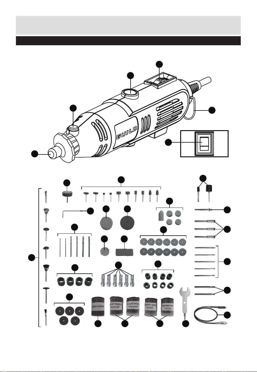
Parts
1
Collet Nut
2
Spindle Lock Button
Carbon Brush Holder (on both sides)
3
4
Speed selector
5
Hook
6
On/Off switch
Accessories
7
Collet (Ø1.6 mm x 1, Ø2.3 mm x 2, Ø3.2 mm x 3) 6
(one in the tool, one in flexible shaft(28), four in the box)
Polishing compound 1
8
Cut-off wheel (15/16” x 1/40” & 15/16” x 1/32”) 65
9
Sanding disk (180/320 grit) 72
10
Cutting wheel fixture (shank size: Ø3.2 mm) 3
11
Grinding disc 12
12
Fiberboard cutting disc 5
13
Grinding bits (shank size: Ø3.2 mm) 10
14
Rubber sanding roll (shank size: Ø3.2 mm) 2
15
Sanding drum 12
16
Brush (shank size: Ø3.2 mm) 7
17
Flap wheel (shank size: Ø3.2 mm) 1
18
Cloth wheel 1
19
HSS twist drlls (shank size: 2 x Ø1.6, 2 x Ø2.3, 2 x Ø3.2) 6
20
HSS cutter (shank size: Ø3.2 mm) 2
21
Felt wheels 6
22
Rubber wheel 1
23
Screw drill (shank size: Ø3.2 mm) 1
24
Diamond grinding bits (shank size: Ø3.2 mm) 5
25
Grinding stone 1
26
Collet spanner 1
27
Flexible shaft 1
28
Locking pin 1
29
10
Customer Helpline 0333 3201989
Page 11
In The Box
Parts
4
3
17
2
6
1
19
22
14
22
23
12
26
7
16
18
29
20
16
15
5
o
I
24
11
25
13
8 9
10
Customer Helpline 0333 3201989
21
28
27
11
Page 12

Operating Instructions
NOTE: Before using the tool, read the instruction book carefully.
Intended Use
This tool is intended for grinding, polishing metal as well as for cutting metal and drilling
in metal and wood.
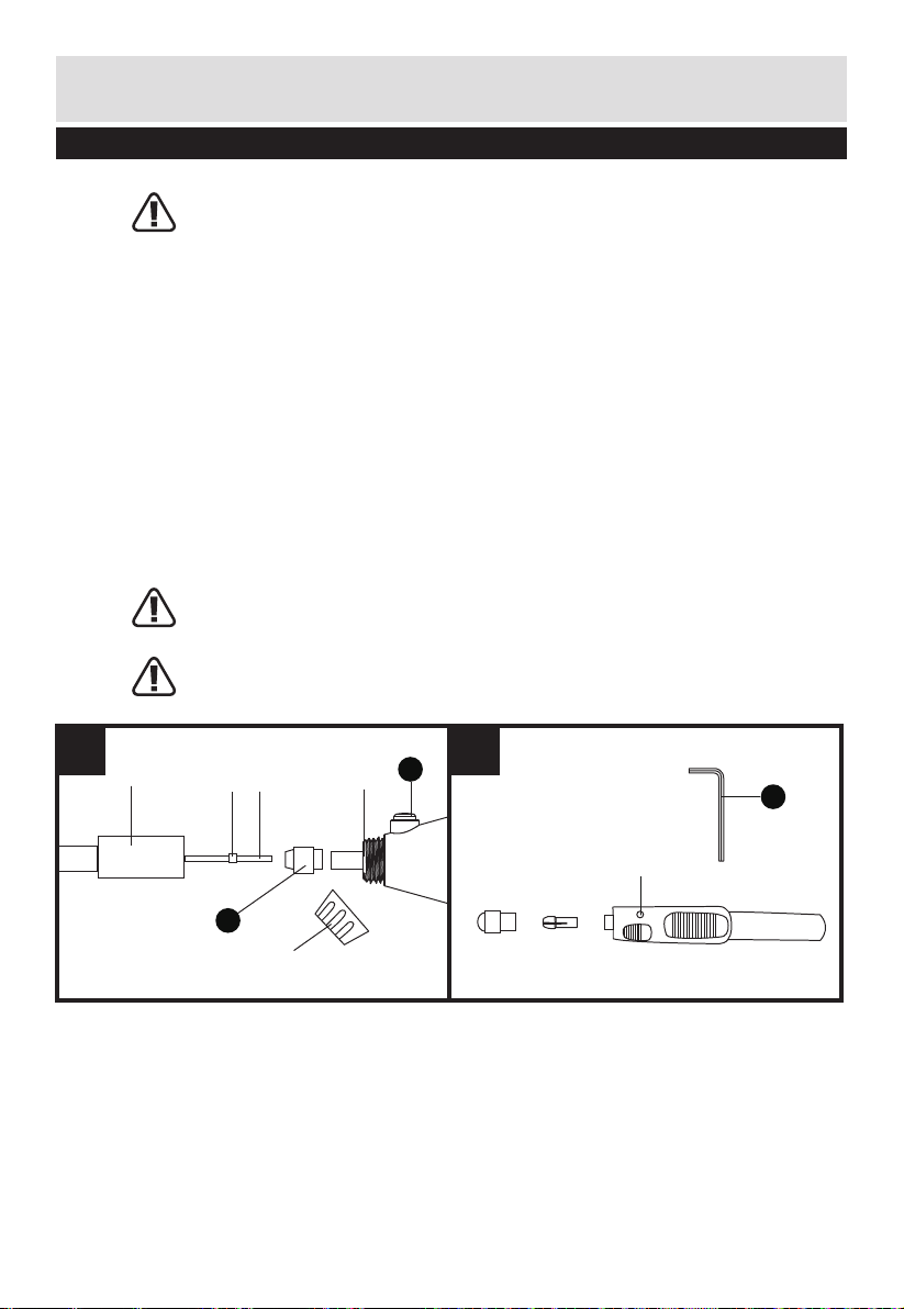
1. CHANGE THE COLLET (SEE FIG A)
Three size of collets are provided to accommodate the different accessories shank sizes.
When using an accessory with a smaller or larger shaft, you will need to change the collet
which matches the shank size of the accessory as follows.
Press the spindle lock button. Loosen the collet nut (1) with the spanner provided. Remove
the collet nut (1) and then fully insert the appropriate size collet (7) into the spindle.
Reinstall the collet nut (1) by finger tight. Do not over-tighten the nut when there is no
accessory in the collet.
WARNING! Fully tighten the collet nut before operation.
Always use the collet which matches the shank size of the accessory you plan to
use. Do not force a larger diameter shank into a smaller collet.
2. FITTING AN ACCESSORY (SEE FIG B, C)
Press the spindle lock button. Hold down and rotate the spindle by hand until the spindle
lock engages with the spindle. Loosen the collet nut anti-clockwise using the spanner if
necessary.
Fully insert the tool shank into the collet. Tighten the collet nut with the spanner but do
not over-tighten. Finally release the spindle lock button.
WARNING: Do not engage the spindle lock button while the tool is running.
A B
1
7
12
Customer Helpline 0333 3201989
2
1
3
Page 13

Operating Instructions
1
2
3
1
7
A B
3. FITTING A CUTTING/SANDING WHEEL (SEE FIG D, E)
First fit he cutting wheel fixture (11) into the collet. Loosen the small screw (a) on the
cutting wheel fixture (11) with top of collet spanner (27). Insert the screw through the
cutting wheel and then screw into the cutting wheel fixture (11). Do not over-tighten
otherwise the wheel may crack.
4. ASSEMBLING THE FELT WHEEL (SEE FIG F)
The felt wheel (22) is used with the screw drill (24). Thread the wheel on to the screw carefully.
The wool wheel must thread down straight on the screw drill, and be turned all the way to the
collar.
C D
2
1
E F
a
11
Customer Helpline 0333 3201989
13
Page 14

Operating Instructions
3
1
2
11
a
C D
E F
5. FITTING THE SANDING ROLL (SEE FIG G1, G2, G3)
To fit the sanding roll, firstly loosen the small screw on top of the hole for rubber wheel,
this will allow the rubber to relax. Slide the sanding roll onto the holder.
To secure, simply tighten the screw and the rubber roll will swell, gripping the sanding
drum.
G1 G2
G3
14
Customer Helpline 0333 3201989
Page 15
Operating Instructions
E F
G1 G2
G3
6. CONNECT THE FLEXIBLE SHAFT TO THE TOOL (SEE FIG H)
WARNING: Never bend the flexible shaft with a radius of less than 152mm when
operating. Always store the flexible shaft carefully to avoid sharp bends when not
in use.
1). Depress spindle lock button (2) and unscrew counter-clockwise the collet nut (1) and
plastic ring (a) from the spindle.
2). Remove the collet from the spindle socket (b).
3). Insert the inner shaft (c) of flexible shaft into the spindle socket (b) until the bump (d)
touches the spindle socket.
4). Screw clockwise the fixed ring (e) of flexible shaft onto housing thread.
5). Tighten the fixed ring (e) by hand. Do not use pliers or spanner.
7. REPLACE THE COLLET & ACCESSORIES ONTO FLEXIBLE SHAFT (SEE FIG I)
1). Rotate the collet of flexible shaft until the hole on the shaft is aligned with the hole
(f) of the flexible shaft collar, insert the locking pin (29) to lock the inner shaft (c) and
then unscrew counter-clockwise the collet nut by supplied spanner (27).
2). Fit accessory to spindle socket of flexible shaft through appropriate size collet
(7). Keep locking pin to lock the inner shaft (c), tighten clockwise the collet nut by
spanner.
WARNING! Fully tighten the collet nut before operation. Always use the collet
which matches the shank size of the accessory you plan to use. Do not force a
small diameter shank into a large collet.
WARNING! Do not attempt to loosen or tighten the collet without locking the
shaft as noted above. Damage to the flexible shaft will result.
H I
e
d c
2
b
29
f
1
a
Customer Helpline 0333 3201989
15
Page 16

Operating Instructions
29
f
e
d c
a
b
1
2
G1 G2
G3
H I
OPERATION
1. SWITCH ON / OFF (SEE FIG J)
NOTE: This tool has been set to the slowest speed before switching on.
To start the tool, press the on/off switch to “I” ON position. To stop, press the switch to
“O” OFF position.
2. SPEED ADJUSTMENT (SEE FIG K)
To achieve the best result when working with different materials, you can adjust the tool
speed. It is adjustable from 10000 to 32000/min.
The tool has a variable speed control for precise speed adjustment. Set it to the required
speed for operation.
NOTE: Select a low speed when working with wood, plastics and polishing.
Generally, select higher speed for small tools while lower speed for larger tools.
From number “1” to “MAX”, the speed is corresponding from 10000 to 32000/min.
3. DRILLING OPERATION
Turn the tool on until full speed. Apply the tool to the workpiece gently. To obtain a good
finish, move the tool in the leftward direction slowly.
NOTE: Apply light pressure on the tool. Excessive pressure will only cause a poor finish
and overloading of the motor.
4. HOLDING THE TOOL
For milling or engraving, hold the tool like a pen. Take care not to cover the ventilation slots.
NOTE: The tool will get warm during normal operation. Observe the rated operating time.
5. USING THE DRILLS
The HSS twist drills (20) are used to cut through all types of steels and steel composites.
6. POLISHING WITH THE FELT WHEEL
After assembling the felt wheel to the screw drill (SEE FIG H & I), it can be used to
polish plastics, metals, steels, jewelry and small parts with polishing compound,
which will give a high luster to the surfaces of the materials. For best results, polishing
accessories should be used at speeds not greater than half speed.
J K
o
I
16
Customer Helpline 0333 3201989
1 2
Page 17

Using Accessories
The chart below lists the description, use speed and scope for some of the small articles
supplied together with the tool by category. To achieve best performance of the tool, it is
strongly recommended that you read it prior to operation, failure to adhere to this may
cause accessories to fail.
NOTE: ALWAYS Wear eye protection Insert the shaft FULLY into the collet. Use ONLY up
to the speeds stated below.
PICTURE DESCRIPTION SPEED FOR USE ON
Grinder bits
Various head styles,
on shafts
Full speed
32,000/min
Metal
Mild steel
Diamond Bits
Various head styles
Wool Wheel
Mounted to screw drill
Sanding/Cutting wheels
Mounted to cutting wheel
fixture
NOTE:
DO NOT over tighten screw
Sanding Roll
Mounted on hold for rubber
wheel
Full speed
32,000/min
Half speed
16,000/min
Half speed
16,000/min
Full speed
32,000/min
Wood Zinc
Plastic Nickel
Copper Mild steel
Metal
Mild steel
Metal
Mild steel
Wood
Metal
Mild steel
Customer Helpline 0333 3201989
17
Page 18

Maintenance & Trouble Shooting
o
I
1 2
29
f
e
d c
a
b
1
2
H I
J K
L M
WARNING: Remove the plug from the socket before carrying out any adjustment,
servicing or maintenance.
REPLACING THE CARBON BRUSHES (SEE FIG L, M, N)
The carbon brushes must be checked on a regular basis. There are two brushes in the tool
and they must be replaced in pairs.
Remove the carbon brush holders with the spanner and check the brushes. If the length of
brush is less than 6mm, replace both brushes. Have the tool run at no load for 15 minutes.
NOTE: Use only the correct type of carbon brushes.
CAUTION: Using the tool with worn brushes (availible from Guild helpline) will
permanently damage the motor.
N
18
6mm(1/4')
Customer Helpline 0333 3201989
Page 19

Maintenance
There are no user serviceable parts in your power tool. Never use water or chemical
cleaners to clean your power tool. Wipe clean with a dry cloth. Always store your power
tool in a dry place. Keep the motor ventilation slots clean. Keep all working controls free
of dust. Occasionally you may see sparks through the ventilation slots. This is normal and
will not damage your power tool.
If the supply cord is damaged, it must be replaced by the manufacturer, its service agent
or similarly qualified persons in order to avoid a hazard.
Trouble Shooting
1. If your power tool does not start, check the plug on the mains supply first.
2. If your power tool use in low efficiency, check the tool speed and type of accessory.
3. If a fault can not be rectified, return the tool to an authorized dealer for repair.
Technical Data
Technical Data Table
Rated voltage 230-240V~50Hz
Rated power 130W
Collet size Ø1.6 / Ø2.3 / Ø3.2mm
Rated no load speed 10000-32000/min
Protection class
Weight 0.68kg
/II
Noise Information
A weighted sound pressure LpA : 71dB(A)
A weighted sound power LwA : 82dB(A)
KpA & KwA=3.0dB(A)
Wear ear protection.
Customer Helpline 0333 3201989
19
Page 20

Technical Data
Vibration Information
Vibration total values (triax vector sum) determined according to EN 60745:
Typical weighted vibration
The declared vibration total value may be used for comparing one tool with another, and
may also be used in a preliminary assessment of exposure.
WARNING: The vibration emission value during actual use of the power tool can
differ from the declared value depending on the ways in which the tool is used
dependant on the following examples and other variations on how the tool is used:
How the tool is used and the materials being cut or drilled.
The tool being in good condition and well maintained
The use the correct accessory for the tool and ensuring it is sharp and in good condition.
The tightness of the grip on the handles and if any anti vibration accessories are used.
And the tool is being used as intended by its design and these instructions.
This tool may cause hand-arm vibration syndrome if its use is not adequately
managed.
WARNING: To be accurate, an estimation of exposure level in the actual conditions
of use should also take account of all parts of the operating cycle such as the
times when the tool is switched off and when it is running idle but not actually doing the
job. This may significantly reduce the exposure level over the total working period.
Helping to minimize your vibration exposure risk.
ALWAYS use sharp chisels, drills and blades.
Maintain this tool in accordance with these instructions and keep well lubricated (where
appropriate).
If the tool is to be used regularly then invest in anti vibration accessories.
Avoid using tools in temperatures of 100C or less.
Plan your work schedule to spread any high vibration tool use across a number of days.
Vibration emission value: a
Uncertainty K = 1.5m/s²
= 1.13m/s²
h
20
Customer Helpline 0333 3201989
Page 21

Environmental Protection
Waste electrical products should not be disposed of with household waste. Please
recycle where facilities exist. Check with your Local Authority or retailer for
recycling advice.
Guarantee
This product is selected for DOMESTIC USE ONLY and not for business use.
This product is guaranteed against manufacturing defects for a period of 24 months. This
does not cover the product where the fault is due to misuse, abuse, use in contravention of
the instructions, or where the product has been the subject of unauthorised modifications
or alterations, or has been the subject of commercial use. In the event of a problem with
the product within the guarantee period please return it to your nearest store. If the item is
shown to have an inherent defect present at the time of sale, the store will provide you with
a replacement. Your statutory rights remain unaffected.
Issue1 08/2015
Declaration of Conformity
This Guild 130W 218 Piece Rotary Tool Kit model number PDM130DC.1 fully complies with
the Machinery Directive 2006/42/EC, Electromagnetic Compatibility Directive 2004/108/
EC(before 2016/04/20) and 2014/30/EC(since 2016/04/20), RoHS Directive 2011/65/EU and
the following harmonized EU standards
EN 60745-2-23:2013
EN 55014-1: 2006 + A1:2009 + A2:2011
EN 55014-2: 1997 + A1:2001 + A2:2008
EN 61000-3-2: 2014
EN 61000-3-3: 2013
This declaration is made under the sole responsibility of Argos Ltd, 489/499 Avebury
Boulevard, Milton Keynes, MK9 2NW
Category Technical Manager signed
Issued 20/10/2015
Customer Helpline 0333 3201989
21
Page 22

Plug Replacement (Uk & Ireland Only)
firmly clamped
If you need to replace the fitted plug then follow the instructions below.
IMPORTANT
The wires in the mains lead are colored in accordance with the following code:
Blue – Neutral
Brown – Live
As the colors of the wires in the mains lead of this appliance may not correspond with the
coloured markings identifying the terminals in your plug, proceed as follows. The wire
which is coloured blue must be connected to the terminal which is marked with N. The
wire which is coloured brown must be connected to the terminal which is marked with L.
WARNING:
Never connect live or neutral wires to the earth terminal of the plug. Only fit an
approved BS1363/A plug and the correct rated fuse.
Note: If a moulded plug is fitted and has to be removed take great care in disposing of the
plug and severed cable, it must be destroyed to prevent engaging into a socket.
13 Amp fuse approved
to BS1362
Connect
Blue to N
(neutral)
Brown L (live)
22
Outer sleeve
Cable grip
Customer Helpline 0333 3201989
Page 23

Page 24

 Loading...