

Page 1
GUILD
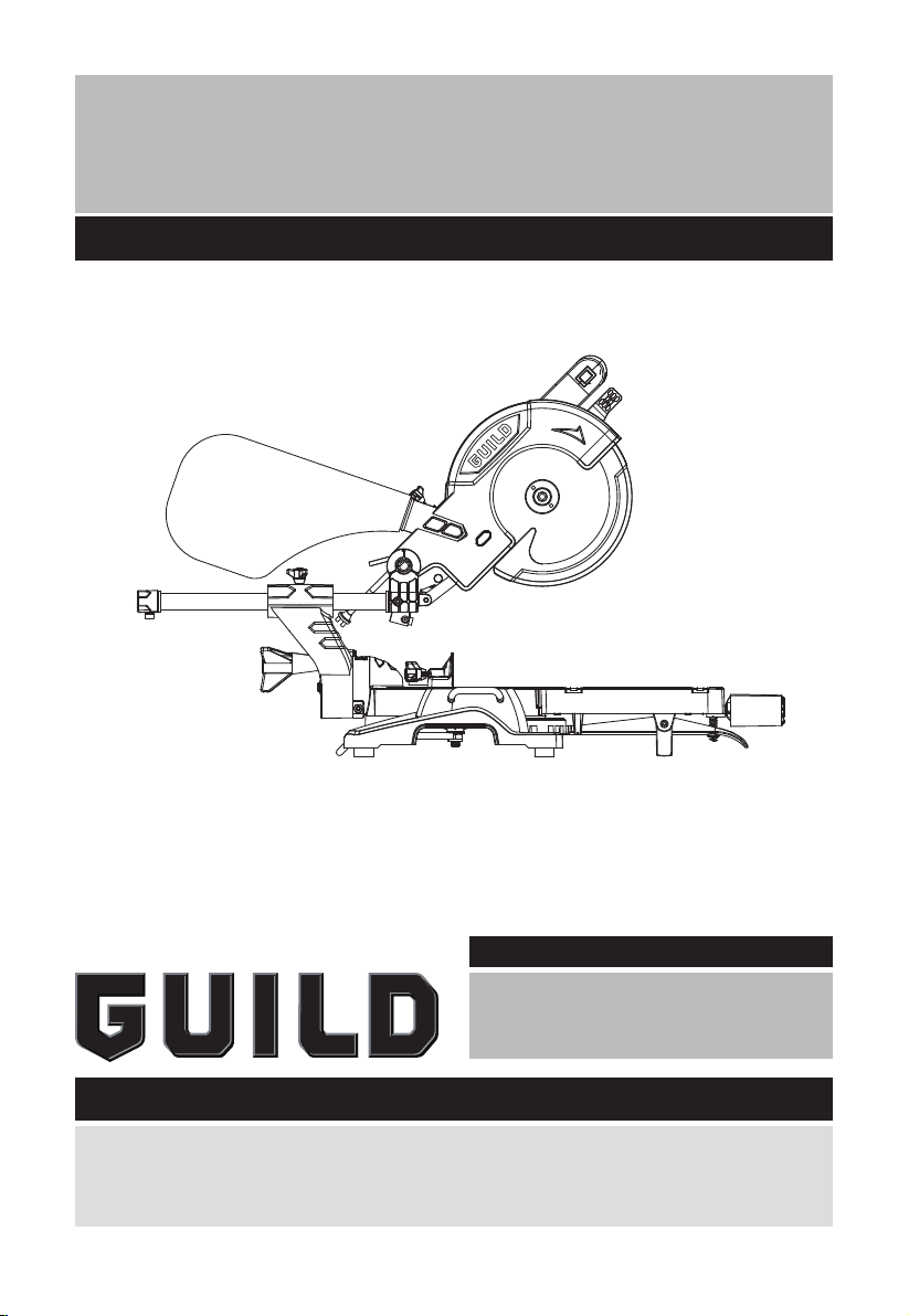
1700W Sliding Mitre Saw
Instruction Manual
BMS210GS
After Sales Support
UK/Ireland 0333 3201989
Help@guildpowertools.co.uk
Important - Please read these instructions fully before operating or maintaining your Guild liding mitre saw
These instructions contain important information that will help you get the best from your guild
sliding mitre saw, ensuring it remains safe to operate.
If you need help or have damaged or missing parts, call the Customer Helpline on 0333 3201989
Page 2

Contents
Safety Information.....................................................................................................3
In The Box..................................................................................................................8
Accessories................................................................................................................8
Assembly Instructions...............................................................................................9
Operating Instructions...............................................................................................9
Maintenance.............................................................................................................15
Technical Data..........................................................................................................18
Environmental Protection........................................................................................19
Guarantee................................................................................................................20
Declaration of Conformity........................................................................................20
Plug Replacement (Uk & Ireland Only)....................................................................21
2
Customer Helpline 0333 3201989
Page 3
Safety Information
Important - Please read these instructions fully before starting assembly
Warning Symbols
The following warning symbols appear throughout this assembly manual and
indicate the appropriate safety measures you should take when assembling and
operating the sliding mitre saw.
To reduce the risk of injury, Please read the instruction manual
Warning
Wear ear protection
Wear eye protection
Wear dust mask
Double insulation
Waste electrical products must not be disposed of with household waste. Please recycle
where facilities exist. Check with your local authorities or retailer for recycling advice.
Laser radiation
Do not stare into beam
Customer Helpline 0333 3201989
3
Page 4

Safety Information
Important - Please read these instructions fully before starting assembly
General Power Tool Safety Warnings
WARNING: When using electric tools basic safety precautions should always be
followed to reduce the risk of fire, electric shock and personal injury including the
following.
Read all these instructions before attempting to operate this product and save these
instructions.
Safe operation
1 - Keep work area clear
- Cluttered areas and benches invite injuries.
2 - Consider work area environment
- Do not expose tools to rain.
- Do not use tools in damp or wet locations.
- Keep work area well lit.
- Do not use tools in the presence of flammable liquids or gases.
3 - Guard against electric shock
- Avoid body contact with earthed or grounded surfaces (e.g. pipes, radiators, ranges,
refrigerators).
4 - Keep other persons away
- Do not let persons, especially children, not involved in the work touch the tool or the
extension cord and keep them away from the work area.
5 - Store idle tools
- When not in use, tools should be stored in a dry locked-up place, out of reach of
children.
6 - Do not force the tool
- It will do the job better and safer at the rate for which it was intended.
7 - Use the right tool
- Do not force small tools to do the job of a heavy duty tool.
- Do not use tools for purposes not intended; for example do not use circular saws to cut
tree limbs or logs.
8 - Dress properly
- Do not wear loose clothing or jewellery, they can be caught in moving parts.
- Non-skid footwear is recommended when working outdoors.
- Wear protective hair covering to contain long hair.
9 - Use protective equipment
- Use safety glasses.
- Use face or dust mask if working operations create dust.
10 - Connect dust extraction equipment
- If the tool is provided for the connection of dust extraction and collecting equipment,
ensure these are connected and properly used.
11 - Do not abuse the cord
- Never yank the cord to disconnect it from the socket. Keep the cord away from heat, oil
and sharp edges.
12 - Secure work
- Where possible use clamps or a vice to hold the work. It is safer than using your hand.
4
Customer Helpline 0333 3201989
Original Instructions
Page 5

Safety Information
Important - Please read these instructions fully before starting assembly
General Power Tool Safety Warnings
13 - Do not overreach
- Keep proper footing and balance at all times.
14 - Maintain tools with care
- Keep cutting tools sharp and clean for better and safer performance.
- Follow instruction for lubricating and changing accessories.
- Inspect tool cords periodically and if damaged have them repaired by an authorized
service facility.
- Inspect extension cords periodically and replace if damaged.
- Keep handles dry, clean and free from oil and grease.
15 - Disconnect tools
- When not in use, before servicing and when changing accessories such as blades, bits
and cutters, disconnect tools from the power supply.
16 - Remove adjusting keys and wrenches
- Form the habit of checking to see that keys and adjusting wrenches are removed from
the tool before turning it on.
17 - Avoid unintentional starting
- Ensure switch is in “off” position when plugging in.
18 - Use outdoor extension leads
- When the tool is used outdoors, use only extension cords intended for outdoor use
and so marked.
19 - Stay alert
-
Watch what you are doing, use common sense and do not operate the tool when you are tired.
20 - Check damaged parts
- Before further use of tool, it should be carefully checked to determine that it will
operate properly and perform its intended function.
- Check for alignment of moving parts, binding of moving parts, breakage of parts,
mounting and any other conditions that may affect its operation.
- A guard or other part that is damaged should be properly repaired or replaced by an
authorized service centre unless otherwise indicated in this instruction manual.
- Have defective switches replaced by an authorized service centre.
- Do not use the tool if the switch does not turn it on and off.
21 - Warning
- The use of any accessory or attachment other than one recommended in this
instruction manual may present a risk of personal injury.
22 - Have your tool repaired by a qualified person
- This electric tool complies with the relevant safety rules. Repairs should only be
carried out by qualified persons using original spare parts, otherwise this may result
in considerable danger to the user.
23 - If the replacement of the supply cord is necessary, this has to be done by the
manufacturer or his agent in order to avoid a safety hazard.
24 - For tools intended to be connected to a water supply:
– Replacement of the plug or the supply cord shall always be carried out by the
manufacturer of the tool or his service organisation,
– Keep water clear off the electrical parts of the tool and away from persons in the
working area.
Customer Helpline 0333 3201989
5
Page 6

Safety Information
Important - Please read these instructions fully before starting assembly
Mitre Saw Safety Instruction
Safety precautions
- Do not use saw blades which are damaged or deformed;
- Replace the table insert when worn;
- Use only saw blades recommended by the manufacturer which conform to en 847-1;
- Do not use saw blades manufactured from high speed steel;
- Wear suitable personal protective equipment when necessary, this could include:
- Hearing protection to reduce the risk of induced hearing loss;
- Eye protection when using the tool.
- Respiratory protection to reduce the risk of inhalation of harmful dust.
- Gloves for handling saw blades (saw blades shall be carried in a holder
wherever practicable) and rough material;
- Connect the saw to a dust collecting device when sawing wood. In addition the
operator shall be informed of factors that influence exposure of dust and the
precautions mentioned e.G. Type of material to be machined and the importance of
local extraction (capture or source) and proper adjustment of hoods/baffles/chutes;
Safe operation
- Select the correct saw blade for the material to be cut;
- Do not use the saw to cut other materials than those recommended by the
manufacturer;
- Lifting and transportation information: information shall include where to lift and
support the mitre saw and when necessary a warning not to use guards for this
purpose;
- Do not use the saw without the guards in position, in good working order and properly
maintained;
- Ensure that the arm is securely fixed when bevelling;
- Keep the floor area around the machine level, well maintained and free of loose
materials e.G. Chips and cut-offs;
- Provide adequate general or localised lighting;
- The operator is adequately trained in the use, adjustment and operation of the
machine;
- Use correctly sharpened saw blades. Observe the maximum speed marked on the saw
blade;
- Ensure that any spacers and spindle rings used are suitable for the purpose as stated
by the manufacturer;
- When fitted with laser, no exchange with different type of laser is permitted. Repairs
shall only be carried out by the laser manufacturer or an authorised agent;
- Blade replacement procedure including the method for repositioning and a warning
that this must be carried out correctly;
- Refrain from removing any cut-offs or other parts of the workpiece from the cutting
area whilst the machine is running and the saw head is not in the rest position;
- Always to clamp work pieces to the saw table
- To ensure before each cut that the machine is stable,
- If needed, to fix the machine to a work bench or the like,
- If needed, to support long work pieces with appropriate additional supports;
- Replace table insert when worn.
6
Customer Helpline 0333 3201989
Page 7

Safety Information
Important - Please read these instructions fully before starting assembly
General Safety Warnings for your Laser
WARNING: Read all safety warnings and all instructions. Failure to follow the
warnings and instructions may result in serious injury.
Save all warnings and instructions for future reference.
These lasers do not normally present an optical hazard although staring at the beam may
cause flash blindness.
Do not stare directly at the laser beam. A hazard may exist if you deliberately stare into
the beam, please observe all safety rules as follows:
1. The laser shall be used and maintained in accordance with the manufacturer’s
instructions.
2. Never aim the beam at any person or an object other than the work piece.
3. The laser beam shall not be deliberately aimed at another person and shall be
prevented from being directed towards the eye of a person for longer than 0.25
seconds area.
4. Always ensure the laser beam is aimed at a sturdy work piece without reflective
surfaces, e.g. wood or rough-coated surfaces are acceptable. Bright shiny reflective
sheet steel or similar is not suitable for laser applications as the reflective surface
may direct the laser beam back at the operator.
5. Do not change the laser device with a different type. The manufacturer or an
authorized agent must carry out repairs.
6. CAUTION: Use of controls or adjustments other than those specified herein may result
in hazardous radiation exposure.
Additional safety warning for class 2 laser
The laser device fitted to this tool is CLASS 2 with a maximum radiation of 3 mW and 650
nm wavelength.
CLASS 2 LASER RADIATION, DO NOT STARE INTO BEAM
Customer Helpline 0333 3201989
7
Page 8
In The Box
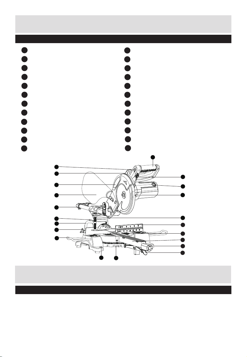
Parts
1
Handle
2
Safety release lever
3
Carbon brush cap
4
Lower blade guard
5
Laser guide
6
Fence
7
Rotary table
8
Mitre table lock knob
Rotary table handle
9
10
Mitre latch
11
Rotary table mitre angle scale
12
Mounting hole
21
20
19
18
13
Table extension rail
14
Work clamp securing knob
15
Work clamp
16
Bevel lock lever
17
Slide rod
18
Dust bag
19
Upper fixed blade guard
20
Transportation handle
21
Laser switch
22
Support stand (See Fig. B2)
23
Trigger switch (See Fig. F)
24
Spindle lock button (See Fig. P2)
1
2
3
4
17
16
15
14
13
Accessories
Blade spanner 1pc
Dust bag 1pc
Work clamp 1pc
Extension rail 2pc
AAA battery cells for laser guide 2pc
8
12
11
Customer Helpline 0333 3201989
5
6
7
9
8
10
Page 9

Assembly Instructions
A B1
NOTE: Before using the tool, read the instruction book carefully.
Intended Use
This tool is intended as a stationary machine for making straight lengthways and
crossways cuts in wood. Horizontal mitre angles of -45° to +45° as well as vertical bevel
angles of 0° to +45° are possible.
ASSEMBLY
WARNING: To prevent the accidental starting that could cause possible serious
personal injury, ALWAYS assemble all parts to your saw BEFORE connecting it to
the power supply. The saw should NEVER be connected to a power supply when you are
assembling parts, making adjustments, installing or removing blades, or when not in
use.
1. DUST EXTRACTION PORT (SEE FIG A)
To reduce build up of saw dust and maintain top efficiency of cutting, saw dust
collection can be achieved by clipping a dust bag on the dust extraction port.
A dust bag is provided for use on your mitre saw. To install it, simply fit the dust bag over
the extraction port on the upper blade guard.
To empty the dust bag, remove it from the dust exhaust port, open the dust bag by
unzipping the slide fastener.
2. TABLE EXTENSION RAIL (SEE FIG B1)
To install table extension rail, simply insert ends of extensions into the holes in either or
both sides of the base. Secure them in place by tightening the clamp screw on the base.
The table extension rail is used for supporting long work pieces.
Customer Helpline 0333 3201989
9
Page 10

B2 B3
22
DC
Assembly Instructions
3. THE SUPPORT STAND (SEE FIG B2, B3)
Pull the support stand to its extreme, as shown in Fig B2, B3.
WARNING: Always keep the support stand at its extreme out position when using
the product.
4. WORK CLAMP (SEE FIG C)
1) The work clamp can be fitted on either side of the saw and is fully adjustable to suit the
size of the workpiece.
2) Do not operate the saw without clamping the workpiece.
3) Make sure that the work clamp securing screws are tightened.
5. MOUNTING HOLES (SEE FIG D)
Before use, the saw can be fixed to a firm, level surface with the 4 mounting bolts (not
supplied).
Four holes are provided in the base of the saw to enable it to be fixed to a bench, or
other supporting surface.
To mount the saw, proceed as follows:
1) Locate and mark where the saw is to be mounted.
2) Drill 4 holes through the surface.
3) Place the sliding mitre saw on the surface aligning holes in base with holes drilled in
the surface. Install bolts, washers and hex nuts.
10
Customer Helpline 0333 3201989
Page 11

Operating Instructions
B2 B3
C D
1. RELEASING THE SAW HEAD (SEE FIG E1, E2)
When boxed or during storage, transportation, the saw head is locked in the down position.
To release the head ready for operation, apply downward pressure and pull out the lock
pin (a), then turn 90°left or right to lock it in place. The head will be raised gently to upper
position.
2. STARTING THE SAW (SEE FIG F)
Depress the trigger switch (23). Allow the motor to reach full speed. When the blade has reached
maximum speed, unlock the blade guard by operating the safety release lever (2) using your thumb.
3. CHOP CUT (SEE FIG G1, G2)
Chop cut is used mainly for narrow pieces, i.e. the lock screw of slide rod is tightened and
the head assembly is lowered to cut through the workpiece.
1) Connect the machine to power outlet, ensure that the mains cable is clear of the blade
and base plate.
2) Position the material to be cut on the rotary table, ensure it is firmly clamped so that it
will not move during cutting.
3) Slide the cutting head to rear position as far as it will go and lock the slide rod by rotating
the slide rod securing knob clockwise.
Ensure that the rotary table handle and bevel lock lever (16) are tightened before cutting.
4) Press the trigger switch and allow the saw blade to run up the speed.
5) Still holding in the trigger, using your thumb simply press the safety release lever. It will
then be possible to push the saw head down by the handle.
6) Continue to move the saw head down smoothly and make the cut exerting only gentle
pressure on the downward stroke, letting the saw do the work.
E1 E2
Before
a
After
F G1
23
2
Customer Helpline 0333 3201989
11
Page 12

Operating Instructions
16
H2 I1
4. CROSS PULL CUT
Cross pull cut is used mainly for wide pieces, allowing you to cut wider pieces of wood, i.e. the
slide rod securing knob is loose, the saw head is pulled towards the operator, the saw head is
lowered to the workpiece and then pushed to the rear of saw to make a cut to do this, follow the
procedures below:
1) Loosen the slide rod securing knob .
2) Before switching on, pull the saw head towards you whilst in the upright position, until the
blade clears the workpiece or to its
maximum extension if blade can not clear the workpiece.
3) Start the saw.
4) Lower the saw head into the workpiece.
5) Push the saw head forwards (towards the full rear position) to complete the cut.
6) When cutting is finished, release the trigger switch and allow the blade to stop rotating before
lifting the saw head up away from the workpiece.
WARNING: Never pull the saw towards you during a cut. The blade can suddenly
climb up on top of the workpiece and force itself towards you.
5. MITRE CUT (SEE FIG H1, H2)
A mitre cut is made at 0° bevel and any mitre angle in the range from 45° left to 45° right. It
can be made as either a chop cut or
a cross pull cut depending on the width of the workpiece.
For most convenient operation, your sliding mitre saw is equipped with mitre detents for
fast and accurate mitre cuts of common
mitre angles (Left: 45°, 30°, 22.5°, 15°;0°; Right: 0° ,15°, 22.5°, 30°, 45°).
The mitre table lock knob (8) is used to lock the table at the desired mitre angle. To adjust
the mitre angle, loosen the rotary table handle (9) counter-clockwise and raise the mitre
latch (10) gently and adjust to the desired position, then release the mitre latch (10) and
tighten the mitre table lock knob (8) clockwise.
G2 H1
G H
12
Customer Helpline 0333 3201989
Page 13

Operating Instructions
23
16
2
F G1
G2 H1
H2 I1
16
H2 I1
6. BEVEL CUT (SEE FIG I1, I2)
A bevel cut is made at 0° miter and any bevel angle in the range of 0° to 45° left.
It can be made as either a chop cut or a cross pull cut depending on the width of the
workpiece.
The saw can be moved from the normal 0° perpendicular position to an angled position
down to 45° from the horizontal, on the left only.
Loosen the bevel lock lever (16) and tilt the saw head to the left, until the desired angle is
reached on the bevel scale. Re-tighten the bevel lock lever and make your cut.
7. COMPOUND CUT (SEE FIG J)
A compound cut is a cut requiring both a miter setting and a bevel setting. It can be made
as either a chop cut or a cross pull cut
depending on the width of workpiece.
Compound miter cuts can be achieved by setting both the miter and bevel angles
simultaneously.
Follow the procedures for miter and bevel cuts to achieve the desired angles.
I2 J
Customer Helpline 0333 3201989
13
Page 14

Operating Instructions
16
15mm
c
d
e
H2 I1
I2 J
K1 K2
9. OPERATION INSTRUCTION OF LASER GUIDE (SEE FIG L1, L2)
The laser guide (5) equipped with this machine is for the purpose of precision cutting.
Make sure the batteries are fitted in the laser guide before carrying out precision
cutting. To fit the batteries, remove the battery storage cover, insert 2xAAA
batteries, then replace cover.
NOTE: Ensure correct battery polarity. To use the laser guide, simply slide the laser
on/off switch at the “I” position, the laser guide then projects a visible red line on the
workpiece surface, make your cut along the red line.
Switch off the laser after cutting.
NOTE: The sawdust may “block” the laser beam, clean the laser generator periodically.
WARNING: Never stare directly into the laser beam and never point the beam at
anybody.
L1 L2
DANGER: Laser radiation. Avoid direct eye contact with light source.
5
14
Customer Helpline 0333 3201989
Page 15

Maintenance
15mm
c
d
e
5
I2 J
K1 K2
L1 L2
WARNING:
servicing or maintenance.
When all the adjustments, settings or maintenance have been done, make sure that all keys and
wrenches have been removed and that all screws, bolts and other fittings are securely tightened.
There are no user serviceable parts in your power tool. Never use water or chemical
cleaners to clean your power tool. Wipe clean with a dry cloth. Always store your power tool
in a dry place. Keep the motor ventilation slots clean. Keep all working controls free of dust.
Occasionally you may see sparks through the ventilation slots. This is normal and will not
damage your power tool.
If the supply cord of this power tool is damaged, it must be replaced by a specially prepared
cord available through the service
1. PRECISION SETTING OF ANGLES (SEE FIG M1,M2)
While the machine has been factory set, it is advisable that the 0° setting of the rotary table
and the 90° perpendicular setting of the tilt be checked, as these positions may have moved
in transit. (Ensure power is disconnected while making these adjustments).
To confirm the 0° rotary table setting, set the rotary table at 0° and tighten the rotary table
locking knob. Check that the angle between the straight guide and the blade is 90° using a
try square (b), not supplied) as shown in Fig. M1. If the angle requires adjustment, loosen
the locking screws (c) for straight guide, and align the fence against the try square.
Re-tighten the locking screws (c) for straight guide.
Remove the plug from the socket before carrying out any adjustment,
M1 M2
b
c
Customer Helpline 0333 3201989
15
Page 16

Maintenance
g
g
i
j
N1 N2
O1 O2
2. CHANGING THE SAW BLADE (SEE FIG P1-P4)
Disconnect the saw from the power supply.
Press the blade spindle lock (24) and rotate the blade until it is locked, then loosen and
remove the blade securing bolt, the outer flange with the socket wrench in clockwise
direction.
NOTE: Blade securing bolt has a left hand thread.
Remove the blade, (we recommend the use of a stout glove for this). Clean any saw dust
and debris from the arbor and saw blade securing flanges.
To refit the blade, follow the above procedure in reverse order. If you want to take the inner
flange out for cleaning, refit it as shown in Fig. P4
CAUTION: ALWAYS install the blade with the blade teeth and the arrow printed on the side
of the blade pointing down at the front of the saw. The direction of blade rotation is also
stamped with an arrow on the upper blade guard.
P1 P2
P3 P4
24
16
Customer Helpline 0333 3201989
Page 17

Maintenance
3. REPLACING THE CARBON BRUSHES
Check the carbon brushes regularly. If the carbon brushes are worn down to about
4mm, replace them with the new set (not supplied). It must be replaced in pairs.
With a suitable slotted screwdriver turn the cap anti-clockwise until the carbon brush is
released, replace the brush and make sure that they locate well and are secured within
the brush retainer.
4. MOVING THE SAW
1) When transporting the saw with fixed locations, make sure that the saw head is
locked in the lower position.
2) The rotary table locking knob, the bevel lock lever and the slide rod securing knob,
must all be securely tightened.
3) Use the transportation handle to lift the saw. Do not lift the saw by the switch handle.
Customer Helpline 0333 3201989
17
Page 18

Technical Data
Technical Data Table
Rated voltage 230-240V~50Hz
Rated Input power 1700W
No load speed 4500 /min
Bevel capacity 0-45°
Mitre capacity 0-45° L&R
Blade size 210 mm
Protection class
Machine weight 9.48 kg
Cutting Capacity
Max cutting mitre/bevel 0°/90° 300x60mm
Max cutting mitre/bevel 45°/90° 300x35mm
Max cutting mitre/bevel 0°/45° 210x60mm
Max cutting mitre/bevel (R) 45°/45° 210x35mm
Noise Information
A weighted sound pressure LpA : 105.99dB(A)
A weighted sound power LwA : 118.99dB(A)
KpA & KwA=3.0dB(A)
Wear ear protection when sound pressure is over: 80dB(A)
/II
18
ATTENTION: Through poor conditions of the electrical MAINS, shortly voltage drops can
appear when starting the EQUIPMENT. This can influence other equipment (Eg. Blinking
of the lamp). If the MAINS-IMPEDANCE Zsysmax = 1.989Ω, such disturbances are not
expected. (In case of need, you may contact your local supply authority for further
information).
Customer Helpline 0333 3201989
Page 19

Environmental Protection
Waste electrical products must not be disposed of with household waste. Please
recycle where facilities exist. Check with your local authorities or retailer for
recycling advice.
Customer Helpline 0333 3201989
19
Page 20

Guarantee
This product is selected for DOMESTIC USE ONLY and not for business use.
This product is guaranteed against manufacturing defects for a period of 24 months. This
does not cover the product where the fault is due to misuse, abuse, use in contravention of
the instructions, or where the product has been the subject of unauthorised modifications
or alterations, or has been the subject of commercial use. In the event of a problem with
the product within the guarantee period please return it to your nearest store. If the item is
shown to have an inherent defect present at the time of sale, the store will provide you with
a replacement. Your statutory rights remain unaffected.
Declaration of Conformity
This Guild 1700W Sliding Mitre Saw model number BMS210GS fully complies with the
Machinery Directive 2006/42/EC, Electromagnetic Compatibility Directive 2004/108/
EC(before 2016/04/20) and 2014/30/EC(since 2016/04/20), RoHS Directive 2011/65/EU and
the following harmonized EU standards
EN 61029-1: 2009/A11:2010
EN 61029-2-9:2012/A11:2013
EN 55014-1:2006 + A1:2009 + A2:2011
EN 55014-2:1997 + A1:2001 + A2:2008
EN 61000-3-2:2006+A1:2009+A2:2009
EN 61000-3-11: 2000
This declaration is made under the sole responsibility of Argos Ltd, 489/499 Avebury
Boulevard, Milton Keynes, MK9 2NW
Issue1 08/2015
20
Category Technical Manager signed
Issued 20/10/2015
Customer Helpline 0333 3201989
Page 21

Plug Replacement (Uk & Ireland Only)
firmly clamped
If you need to replace the fitted plug then follow the instructions below.
IMPORTANT
The wires in the mains lead are colored in accordance with the following code:
Blue – Neutral
Brown – Live
As the colors of the wires in the mains lead of this appliance may not correspond with the
coloured markings identifying the terminals in your plug, proceed as follows. The wire
which is coloured blue must be connected to the terminal which is marked with N. The
wire which is coloured brown must be connected to the terminal which is marked with L.
WARNING:
Never connect live or neutral wires to the earth terminal of the plug. Only fit an
approved BS1363/A plug and the correct rated fuse.
Note: If a moulded plug is fitted and has to be removed take great care in disposing of the
plug and severed cable, it must be destroyed to prevent engaging into a socket.
13 Amp fuse approved
to BS1362
Connect
Blue to N
(neutral)
Brown L (live)
Outer sleeve
Cable grip
Customer Helpline 0333 3201989
21
Page 22

Page 23

Page 24

 Loading...