

Page 1
GUILD
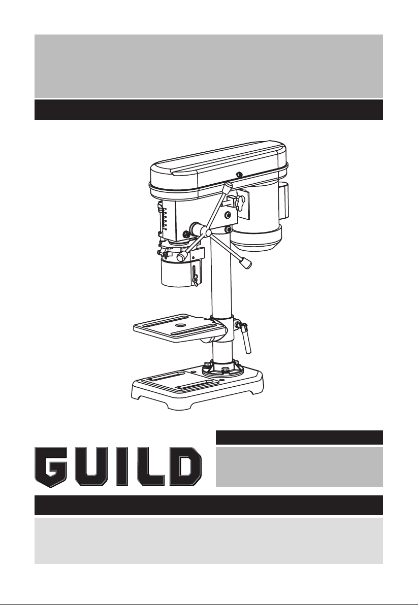
350W 13mm Drill Press
Instruction Manual
BDP13G
After Sales Support
UK/Ireland 0333 3201989
Help@guildpowertools.co.uk
Important - Please read these instructions fully before operating or maintaining your Guild drill press
These instructions contain important information that will help you get the best from your Guild
drill press, ensuring it remains safe to operate.
If you need help or have damaged or missing parts, call the Customer Helpline on 0333 3201989
Page 2

Contents
Safety Information ����������������������������������������������������������������������������������������������������3
In The Box ����������������������������������������������������������������������������������������������������������������� 6
Accessories ��������������������������������������������������������������������������������������������������������������6
Assembly Instructions ����������������������������������������������������������������������������������������������7
Operating Instructions �������������������������������������������������������������������������������������������� 10
Working Hints For Your Drill Press ������������������������������������������������������������������������� 11
Maintenance �����������������������������������������������������������������������������������������������������������12
Technical Data �������������������������������������������������������������������������������������������������������� 12
Environmental Protection ���������������������������������������������������������������������������������������13
Guarantee ��������������������������������������������������������������������������������������������������������������� 13
Declaration of Conformity ���������������������������������������������������������������������������������������13
Plug Replacement (Uk & Ireland Only) ������������������������������������������������������������������� 14
2
Customer Helpline 0333 3201989
Page 3

Safety Information
Important - Please read these instructions fully before starting assembly
Warning Symbols
The following warning symbols appear throughout this assembly manual and
indicate the appropriate safety measures you should take when assembling and
operating the drill press.
To reduce the risk of injury, Please read the instruction manual
Warning
Wear ear protection
Wear eye protection
Wear dust mask
Waste electrical products must not be disposed of with household waste. Please recycle
where facilities exist. Check with your local authorities or retailer for recycling advice.
Customer Helpline 0333 3201989
3
Page 4

Safety Information
Important - Please read these instructions fully before starting assembly
Safety Instructions
“
WARNING!
followed to reduce the risk of fire, electric shock and personal injury including the
following.
Read all these instructions before attempting to operate this product and save these instructions”.
Maintenance and Servicing
Remove the plug before carrying out any adjustment, servicing or maintenance
Safe operation
1 - Keep work area clear
- Cluttered areas and benches invite injuries.
2 - Consider work area environment
- Do not expose tools to rain.
- Do not use tools in damp or wet locations.
- Keep work area well lit.
- Do not use tools in the presence of flammable liquids or gases.
3 - Guard against electric shock
- Avoid body contact with earthed or grounded surfaces {e.g. pipes, radiators, ranges,
refrigerators).
4 - Keep other persons away
- Do not let persons, especially children, not involved in the work touch the tool or the
extension cord and keep them away from the work area
5 - Store idle tools
-When not in use, tools should be stored in a dry locked-up place, out of reach of children.
6 - Do not force the tool
- It will do the job better and safer at the rate for which it was intended.
7 - Use the right tool
- Do not force small tools to do the job of a heavy duty tool.
- Do not use tools for purposes not intended; for example do not use circular saws to cut
tree limbs or logs.
8 - Dress properly
- Do not wear loose clothing or jewellery, they can be caught in moving parts.
- Non-skid footwear is recommended when working outdoors.
- Wear protective hair covering to contain long hair.
9 - Use protective equipment
- Use safety glasses.
- Use face or dust mask if working operations create dust.
10 - Connect dust extraction equipment
- If the tool is provided for the connection of dust extraction and collecting equipment,
ensure these are connected and properly used.
11 - Do not abuse the cord
- Never yank the cord to disconnect it from the socket Keep the cord away from heat, oil
and sharp edges.
12 - Secure work
- Where possible use damps or a vice to hold the work. It is safer than using your hand.
13 - Do not overreach
When using electric tools basic safety precautions should always be
4
Customer Helpline 0333 3201989
Original Instructions
Page 5

Safety Information
Important - Please read these instructions fully before starting assembly
Safety Instructions
- Keep proper footing and balance at all times.
14 - Maintain tools with care
- Keep cutting tools sharp and clean for better and safer performance.
- Follow instruction for lubricating and changing accessories.
- Inspect tool cords periodically and if damaged have them repaired by an authorized
service facility.
- Inspect extension cords periodically and replace if damaged.
- Keep handles dry, clean and free from oil and grease.
15 - Disconnect tools
- When not in use, before servicing and when changing accessories such as blades, bits
and cutters, disconnect tools from the power supply.
16 - Remove adjusting keys and wrenches
- Form the habit of checking to see that keys and adjusting wrenches are removed from
the tool before turning it on.
17 - Avoid unintentional starting
- Ensure switch is in “off” position when plugging in
18 - Use outdoor extension leads
- When the tool is used outdoors, use only extension cords intended for outdoor use and so
marked.
19 -Stay alert
- Watch what you are doing, use common sense and do not operate the tool when you are
tired.
20 - Check damaged parts
- Before further use of tool, it should be carefully checked to determine that it will operate
properly and perform its intended function.
- Check for alignment of moving parts, binding of moving parts, breakage of parts,
mounting and any other conditions that may affect its operation.
- A guard or other part that is damaged should be properly repaired or replaced by an
authorized service centre unless otherwise indicated in this instruction manual.
- Have defective switches replaced by an authorized service centre.
- Do not use the tool if the switch does not turn it on and off.
21 - Warning
- The use of any accessory or attachment other than one recommended in this instruction
manual may present a risk of personal injury.
22 - Have your tool repaired by a qualified person
- This electric tool complies with the relevant safety rules. Repairs should only be
carried out by qualified persons using original spare parts, otherwise this may result in
considerable danger to the user.
23 - If the replacement of the supply cord is necessary, this has to be done by the
manufacturer or his agent in order to avoid a safety hazard.
24 - For tools intended to be connected to a water supply:
– Replacement of the plug or the supply cord shall always be carried out by the
manufacturer of the tool or his service organisation,
– Keep water clear off the electrical parts of the tool and away from persons in the
working area.
Customer Helpline 0333 3201989
5
Page 6

In The Box
Parts
1
Allen keys
2
Chuck key
3
Handles
4
Bolts and washers
5
Support column
6
Adjustable guard
7
Adjustable tilting table
8
Headstock/motor assembly
9
Chuck
10
Base plate
11
Screws (SEE FIG E)
12
Guard securing screw x 3 (SEE FIG F)
13
Locking nut (SEE FIG H)
14
Spindle alignment adjustment screw
(SEE FIG H)
15
Belt cover securing screw (SEE FIG I)
16
Tension adjustor screw (SEE FIG J)
17
Motor securing bolts (SEE FIG K)
18
Table securing bolt (SEE FIG N)
19
Depth stop locking nuts, pointer and scale
(SEE FIG P)
20
Switch “OFF” (SEE FIG Q)
21
Switch “ON” (SEE FIG Q)
22
Safety interlock switch (SEE FIG L)
Accessories
Chuck key 1pc
Allen key 2pc
6
Customer Helpline 0333 3201989
Page 7

Assembly Instructions
NOTE: Before using the tool, read the instruction book carefully.
Intended Use
This tool is intended for drilling in wood, metal and plastic.
1� UNPACKING YOUR TOOL
Carefully unpack all of the contents and lay them out on the floor (SEE FIG A). NB To prevent
corrosion some of the parts have been coated in a fine layer of oil, it is advised to assemble
this product in a working area to prevent damage to upholstery or carpets. Check contents
against check list below. Retain packaging until all parts are accounted for and assembly
has been completed.
Lift out base plate and remove protective paper and place on workbench.
Inside the small box you will find the chuck, three handles, three set bolts, three washers,
two allen keys and chuck key. Place on workbench.
Lift worktable out and remove protective paper. Put on workbench. Remove headstock
and motor assembly and put on workbench. Remove column and plastic guard. Put plastic
guard away for time being.
A
1
2
7
8
3
4
9
5
10
6
Customer Helpline 0333 3201989
7
Page 8

Assembly Instructions
2� ASSEMBLY
Take base plate and select a suitable place on workbench for mounting (SEE FIG B). Be
aware of table legs and anything, which might reduce access to underneath:
Locate the two mounting holes. Select suitable length bolts, washers and nuts (not
supplied). Using base as a template drill two holes through the workbench. Bolt the base
plate to the bench. Do not overtighten as this could crack the cast base.
Take the protective paper off the column. Align with the three threaded holes on the base
plate. (SEE FIG C) Secure with the three bolt sets supplied. Again do not use excessive
torque.
Slide the adjustable height work table over the column.
Secure midway with the clamping lever. (SEE FIG D)
CAUTION: The head stock and motor assembly is heavy and may require two person
handling.
Unscrew the two column locating hex-keyed grub screws (11).
Lower the headstock and motor assembly all the way onto the column.
Position the headstock and motor assembly so the front aligns with the centre of the base
plate.
Secure the two hex-keyed grub screws (11) with the supplied key. Retain the key for further
adjustments. (SEE FIG E)
Release the power cable and inspect for damage. Also check the plug for damage.
B C
D E
8
Customer Helpline 0333 3201989
11
Page 9

Assembly Instructions
CAUTION: Do not connect to power supply yet�
Locate the telescopic guard and locate into the spring loaded guard holder. Secure with
small cross headed guard securing screws (12). (SEE FIG F, G)
Attach the three handles into the feed shaft. (SEE FIG H) Raise the adjustable worktable
and place a piece of scrap wood on it.
Locate the chuck and lower the drive spindle. Put on the chuck.
NOTE: It has a tapered shaft and the chuck locates onto this. Bring the chuck into contact
with the wood on the work table and gently apply pressure to lock the chuck onto the
spindle.
F G
12
H
13
14
Customer Helpline 0333 3201989
9
Page 10

Operating Instructions
1� OPERATING THE DRILL PRESS
NOTE: Remove the plug from the socket before carrying out any adjustment, servicing or
maintenance.
1) SELECTING THE CORRECT SPEED FOR DIFFERENT WORK
Refer to speed selection label inside of motor housing and select the speed
required for the job in hand. The tool has five speed settings: 580, 850, 1220, 1650,
2650/min. Choose the setting nearest to the speed selection label recommendation.
2) WORK TABLE ADJUSTMENT
The worktable can rotate + or – 45 degrees. Slacken the table securing bolt (18) and rotate
to desired angle. Re-tighten lock nut. (SEE FIG I)
Slacken the locking lever to the rear of the table. (SEE FIG J)
Move up or down the column. When desired height is reached lock into position.
3) DEPTH STOP ADJUSTMENT
Bring the drill bit in contact with the work piece to be drilled. Take a measurement from
the scale (19) on front of tool (SEE FIG K). Move work piece and add the amount on to the
previous measurement. Move lock nuts down to that required position and lock. This will
give a consistent depth when drilling.
I J
10
18
K
a
19
Customer Helpline 0333 3201989
Page 11

Operating Instructions
4) STARTING AND STOPPING THE DRILL PRESS
The tool is fitted with a no volt switch assembly (SEE FIG L). This means in the event of a
power failure when drilling, the motor will not start once the power is restored until the
switch is reactivated.
NOTE: The cover is fitted with a safety interlock switch (22) (SEE FIG M). If the cover is
not correctly located and secured following a speed change, the main switch may fail to
operate.
Check that the cover if fully closed and secured.
L M
20 21
Working Hints For Your Drill Press
Always lubricate the drill bits with suitable oil before drilling. This will prolong the life of
the
drill bits.
CAUTION: Do not use water-based coolant or any kind of continuous coolant pump.
Customer Helpline 0333 3201989
11
Page 12

Maintenance
Always lubricate the drill bits with suitable oil before drilling. This will prolong the life of the
drill bits.
Caution: Do not use water-based coolant or any kind of continuous coolant pump.
Remove all shavings and dust after each operation. Spread oil onto the unplated surfaces
especially if the tool is not used for long periods.
Lubricate the spindle drive with oil every six months. The spindle guide screw should be
checked periodically to finger tightness.
If the supply cord is damaged, it must be replaced by the manufacturer, its service agent or
similarly qualified persons in order to avoid a hazard.
Technical Data
Technical Data Table
Voltage 240V~50Hz
Power 350W
No load speed 580, 850, 1220, 1650, 2650/min
Max chuck capacity 13mm
Depth of throat 104mm
Table size 160mm x 160mm
Table bevel ±45°
Speed steps number 5
Spindle taper B16
Spindle travel 50mm
Protection class I
Machine weight 12.32kg
Noise Information
A weighted sound pressure LpA : 62dB(A)
A weighted sound power LwA : 75dB(A)
KpA & KwA=3.0dB(A)
Wear ear protection when sound pressure is over: 80dB(A)
12
Customer Helpline 0333 3201989
Page 13

Environmental Protection
Waste electrical products must not be disposed of with household waste. Please
recycle where facilities exist. Check with your local authorities or retailer for
recycling advice.
Guarantee
This product is selected for DOMESTIC USE ONLY and not for business use.
This product is guaranteed against manufacturing defects for a period of 24 months. This
does not cover the product where the fault is due to misuse, abuse, use in contravention of
the instructions, or where the product has been the subject of unauthorised modifications
or alterations, or has been the subject of commercial use. In the event of a problem with
the product within the guarantee period please return it to your nearest store. If the item is
shown to have an inherent defect present at the time of sale, the store will provide you with
a replacement. Your statutory rights remain unaffected.
Issue1 08/2015
Declaration of Conformity
This Guild 350W 13mm Drill Press model number BDP13G fully complies with the
Machinery Directive 2006/42/EC, Electromagnetic Compatibility Directive 2004/108/
EC(before 2016/04/20) and 2014/30/EC(since 2016/04/20), RoHS Directive 2011/65/EU and
the following harmonized EU standards
EN 61029-1: 2009/A11:2010
EN ISO 12100:2010
EN 55014-1: 2006 + A1:2009 + A2:2011
EN 55014-2: 1997 + A1:2001 + A2:2008
EN 61000-3-2/A2:2009
EN 61000-3-3: 2013
This declaration is made under the sole responsibility of Argos Ltd, 489/499 Avebury
Boulevard, Milton Keynes, MK9 2NW
Category Technical Manager signed
Issued 20/10/2015
Customer Helpline 0333 3201989
13
Page 14

Plug Replacement (Uk & Ireland Only)
If you need to replace the fitted plug then follow the instructions below.
IMPORTANT
The wires in the mains lead are colored in accordance with the following code:
Blue = Neutral
Brown = Live
Green/Yellow=Earth
As the colors of the wires in the mains lead of this appliance may not correspond with the
colored markings identifying the terminals in your plug, proceed as follows. The wire which
is colored blue must be connected to the terminal which is marked with N. The wire which
is colored brown must be connected to the terminal which is marked with L. The green/
yellow wire to the earth terminal is marked with E or .
If a 13 AMP (BS 1363/A) Plug is used, a 13 AMP Fuse must be fitted, or if any other type
of plug is used a 13 AMP Fuse must be fitted, either in the Plug or Adaptor, or on the
Distribution Board.
Note: If a moulded plug is fitted and has to be removed take great care in disposing of the
plug and severed cable, it must be destroyed to prevent engaging into a socket.
14
Customer Helpline 0333 3201989
Page 15

Page 16

 Loading...