

Page 1
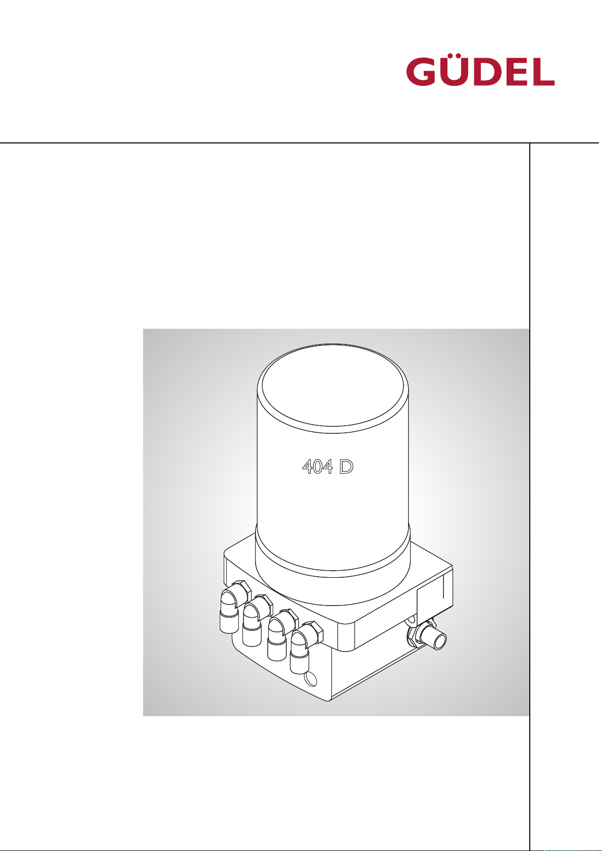
404 DLS
OPERATING MANUAL
BETRIEBSANLEITUNG AUTOMATIC LUBRICATION SYSTEM FLEXXPUMP 404DLS72057594178931083_V7.0_EN-US
B1X.xxxxxxxxx-xxxx
09xxxxx
2018
Automatic lubrication system
FlexxPump 404DLS
Project / Order:
Bill of materials:
Serial number:
Year of manufacture:
Page 2

© GÜDEL
Translation of the original instructions
This manual contains standard illustrations that may deviate from the original.
In the case of special models, options, or technical changes, the scope of delivery may differ from the descriptions here. Reprinting the instructions, in whole
or in part, requires our permission. Subject to change due to technical improvements.
72057594178931083_v7.0_EN-US
Page 3
OPERATING MANUAL Automatic lubrication system
FlexxPump 404DLS
Revision history
Version Date Description
7.0 01.06.2018 Valid as of FlexxPump serial number
Revision history
1601929
Updated:
• Actuate ÜChapter6.4,243
• Lubrication recommendation Ü255
New:
• Splitter Ü229
ÜChapter5.2.3.1,233
6.0 12.04.2018 Updated:
5.0 12.12.2017 Updated:
4.0 08.08.2017 Added:
3.0 27.02.2017 Corrected:
2.0 29.11.2016 Updated:
1.0 29.07.2016 Basic version
Table-1 Revision history
• Lubrication check Ü261
• Lubrication check Ü261
• Lubrication check Ü261
• Standards and guidelines of the Declaration of conformity ÜChapter1,211
• New signatures on Declaration of conformity ÜChapter1,211
• Entire manual updated
72057594178931083_v7.0_EN-US
3
Page 4

Revision history
OPERATING MANUAL Automatic lubrication system
FlexxPump 404DLS
72057594178931083_v7.0_EN-US
4
Page 5

OPERATING MANUAL Automatic lubrication system
FlexxPump 404DLS
Table of contents
Table of contents
1 EC declaration of conformity 11
2 General 13
2.1 Further applicable documentation . . . . . . . . . . . . . . . . . . . . . . . . . . . . . . . . . 13
2.2 Purpose of the document . . . . . . . . . . . . . . . . . . . . . . . . . . . . . . . . . . . . . . . . . . .13
2.3 Explanation of symbols/abbreviations . . . . . . . . . . . . . . . . . . . . . . . . . . . . . . 14
3 Safety 15
72057594178931083_v7.0_EN-US
3.1 General . . . . . . . . . . . . . . . . . . . . . . . . . . . . . . .. . . . . . . . . . . . . . . . . . . . . . . . . . . . . . . .15
3.1.1 Product safety . . . . . . . . . . . . . . . . . . . . . . . . . . . . . . . . . . . . . . . . . . . . . . . . . . . . . . . . . 15
3.1.2 Personnel qualifications . . . . . . . . . . . . . . . . . . . . . . . . .. . . . . . . . . . . . . . . . . . . . . . . . . 16
3.1.2.1 Operating companies. . . . . . . . . . . . . . . . . . . . . . . . . .. . . . . . . . . . . . . . . . . . . . . . . . . . 16
3.1.2.2 Transport specialists. . . . . . . . . . . . . . . . . . . . . . . . . . . . . . . . . . . . . . . . . . . . . . . . . . . . 17
3.1.2.3 Fitters . . . . . . . . . . . . . . . . . . . . . . . . . . . . . . . . . . . . . . . . . . . . . . . . . . . . . . . . . . . . . . . . . 17
3.1.2.4 Commissioning technicians . . . . . . . . . . . . . . . . . . . . . . . . . . . . . . . . . . . . . . . . . . . . . 17
3.1.2.5 Operators . . . . . . . . . . . . . . . . . . . . . . . . . . . . . . . . . . . . . . . . . . . . . . . . . . . . . . . . . . . . . 17
3.1.2.6 Manufacturer's technicians. . . . . . . . . . . . . . . . . . . . . . . . . . . . . . . . . . . . . . . . . . . . . . 18
3.1.2.7 Maintenance technicians . . . . . . . . . . . . . . . . . . . . . . . . . . . . . . . . . . . . . . . . . . . . . . . . .18
3.1.2.8 Service technicians . . . . . . . . . . . . . . . . . . . . . . . . . . . . . . . . . . . . . . . . . . . . . . . . . . . . . 19
3.1.2.9 Disposal specialists . . . . . . . . . . . . . . . . . . . . . . . . . . . . . . . . . . . . . . . . . . . . . . . . . . . . . 19
3.1.3 Disregarding safety regulations. . . . . . . . . . . . . . . . . . . . . . . . . . . . . . . . . . . . . . . . . . 20
3.1.4 Installation instructions . . . . . . . . . . . . . . . . . . . . . . . . .. . . . . . . . . . . . . . . . . . . . . . . . . 20
3.2 Hazard symbols in the manual . . . . . . . . . . . . . . . . . . . . . . . . . . . . . . . . . . . . . 21
3.2.1 Hazard warnings . . . . . . . . . . . . . . . . . . . . . . . . . . . . . . . . . . . . . . . . . . . . . . . . . . . . . . . 21
3.2.2 Explanation of warning symbol . . . . . . . . . . . . . . . . . . . . . . . . . . . . . . . . . . . . . . . . . . 22
3.3 Fundamentals of safety. . . . . . . . . . . . . . . . . . . . . . . .. . . . . . . . . . . . . . . . . . . . . . 23
3.3.1 Product-specific hazards . . . . . . . . . . . . . . . . . . . . . . . . . . . . . . . . . . . . . . . . . . . . . . . . .23
3.3.2 Material safety data sheets (MSDS). . . . . . . . . . . . . . . . . . . . . . . . . . . . . . . . . . . . . . 24
5
Page 6

OPERATING MANUAL Automatic lubrication system
Table of contents
FlexxPump 404DLS
4 Product description 25
4.1 Use . . . . . . . . . . . . . . . . . . . . . . . . . . . . . . . . . . . . . . . . . . . . . . . . . . . . . . . . . . . . . . . . . . . 25
4.1.1 Intended use . . . . . . . . . . . . . . . . . . . . . . . . . . . . . . . . . . . . . . . . . . . . . . . . . . . . . . . . . . . 25
4.1.2 Non-intended use . . . . . . . . . . . . . . . . . . . . . . . . . . . . . . . . . . . . . . . . . . . . . . . . . . . . . . .25
4.2 Product designation . . . . . . . . . . . . . . . . . . . . . . . . . . . . . . . . . . . . . . . . . . . . . . . . . 26
4.3 Technical data . . . . . . . . . . . . . . . . . . . . . . . . . . . . . . . . . . . . . . . . . . . . . . . . . . . . . . . 27
4.3.1 FlexxPump . . . . . . . . . . . . . . . . . . . . . . . . . . . . . . .. . . . . . . . . . . . . . . . . . . . . . . . . . . . . . . 27
4.3.1.1 Dimensions and connections 404DLS . . . . . . . . . . . . . . . . . . . . . . . . . . . . . . . . . . . 27
4.3.1.2 Temperature ranges. . . . . . . . . . . . . . . . . . . . . . . . . . . . . . . . . . . . . . . . . . . . . . . . . . . . 28
4.3.1.3 IP protection class . . . . . . . . . . . . . . . . . . . . . . . . . . . . . . . . . . . . . . . . . . . . . . . . . . . . . 28
4.3.1.4 Operating pressure. . . . . . . . . . . . . . . . . . . . . . . . . . .. . . . . . . . . . . . . . . . . . . . . . . . . . . 28
4.3.2 Splitter . . . . . . . . . . . . . . . . . . . . . . . . . . . . . . . .. . . . . . . . . . . . . . . . . . . . . . . . . . . . . . . . .29
4.3.2.1 Temperature ranges. . . . . . . . . . . . . . . . . . . . . . . . . . . . . . . . . . . . . . . . . . . . . . . . . . . . 29
4.3.2.2 Accuracy of the lubricant distribution . . . . . . . . . . . . . . . . . . . . . . . . . . . . . . . . . . . 29
4.3.2.3 Minimum lubrication quantity . . . . . . . . . . . . . . . . . . . . . . . . . . . . . . . . . . . . . . . . . . . 29
4.3.2.4 Maximum pressure . . . . . . . . . . . . . . . . . . . . . . . . . . . . . . . . . . . . . . . . . . . . . . . . . . . . . 29
4.3.3 Lubricant amount . . . . . . . . . . . . . . . . . . . . . . . . . . .. . . . . . . . . . . . . . . . . . . . . . . . . . . .29
4.3.4 Shelf life of Güdel H1 lubricant. . . . . . . . . . . . . . . . . . . . . . . . . . . . . . . . . . . . . . . . . . 29
5 Design, function 31
5.1 Design . . . . . . . . . . . . . . . . . . . . . . . . . . . . . . . . . . . . . . . . . . . . . . . . . . . . . . . . . . . . . . . . 31
5.1.1 Detailed design of FlexxPump 404DLS . . . . . . . . . . . . . . . . .. . . . . . . . . . . . . . . . . .32
5.2 Function . . . . . . . . . . . . . . . . . . . . . . . . . . . . . . .. . . . . . . . . . . . . . . . . . . . . . . . . . . . . . 33
5.2.1 Functional description . . . . . . . . . . . . . . . . . . . . . . . . . . . . . . . . . . . . . . . . . . . . . . . . . . .33
5.2.2 FlexxPump . . . . . . . . . . . . . . . . . . . . . . . . . . . . . . .. . . . . . . . . . . . . . . . . . . . . . . . . . . . . . . 33
5.2.2.1 404DLS . . . . . . . . . . . . . . . . . . . . . . . . . . . . . . . . . . . . . . . . . . . . . . . . . . . . . . . . . . . . . . . . 33
5.2.3 Splitter . . . . . . . . . . . . . . . . . . . . . . . . . . . . . . . .. . . . . . . . . . . . . . . . . . . . . . . . . . . . . . . . .33
72057594178931083_v7.0_EN-US
5.2.3.1 Function . . . . . . . . . . . . . . . . . . . . . . . . . . . . . . . . . . . . . . . . . . . . . . . . . . . . . . . . . . . . . . . 33
6
Page 7

OPERATING MANUAL Automatic lubrication system
FlexxPump 404DLS
Table of contents
6 Commissioning 35
6.1 Introduction . . . . . . . . . . . . . . . . . . . . . . . . . . . . .. . . . . . . . . . . . . . . . . . . . . . . . . . . . 35
6.1.1 Safety . . . . . . . . . . . . . . . . . . . . . . . . . . . . . . . . . . . . . . . . . . . . . . . . . . . . . . . . . . . . . . . . . . 35
6.1.1.1 Personnel qualifications. . . . . . . . . . . . . . . . . . . . . . . . .. . . . . . . . . . . . . . . . . . . . . . . . . 35
6.2 Transport . . . . . . . . . . . . . . . . . . . . . . . . . . . . . .. . . . . . . . . . . . . . . . . . . . . . . . . . . . . . 35
6.3 Installing . . . . . . . . . . . . . . . . . . . . . . . . . . . . . . .. . . . . . . . . . . . . . . . . . . . . . . . . . . . . . 36
6.3.1 Prerequisites . . . . . . . . . . . . . . . . . . . . . . . . . . . . . .. . . . . . . . . . . . . . . . . . . . . . . . . . . . . . 36
6.3.2 Installing the FlexxPump . . . . . . . . . . . . . . . . . . . . . . . . . . . . . . . . . . . . . . . . . . . . . . . . .37
6.3.3 Connect hydraulics . . . . . . . . . . . . . . . . . . . . . . . . . . .. . . . . . . . . . . . . . . . . . . . . . . . . . . 38
6.3.3.1 404DLS 3-fold . . . . . . . . . . . . . . . . . . . . . . . . . . . . . . . . . . . . . . . . . . . . . . . . . . . . . . . . . 38
6.3.3.2 404DLS 6-fold . . . . . . . . . . . . . . . . . . . . . . . . . . . . . . . . . . . . . . . . . . . . . . . . . . . . . . . . . 39
6.3.3.3 404DLS 10-fold . . . . . . . . . . . . . . . . . . . . . . . . . . . . . . . . . . . . . . . . . . . . . . . . . . . . . . . . .40
6.3.4 Connecting electrical equipment . . . . . . . . . . . . . . . . . . . . . . . . . . . . . . . . . . . . . . . . .41
6.3.4.1 Connecting the 404DLS . . . . . . . . . . . . . . . . . . . . . . . . . . . . . . . . . . . . . . . . . . . . . . . . .42
6.4 Actuate . . . . . . . . . . . . . . . . . . . . . . . . . . . . . . .. . . . . . . . . . . . . . . . . . . . . . . . . . . . . . . .43
6.4.1 Recommended solution, software programming . . . . . . . . . . . . . . . . . . . . . . . . . 44
6.4.2 Switching the FlexxPump on and off. . . . . . . . . . . . . . . . . . .. . . . . . . . . . . . . . . . . . . 45
6.4.3 Lubrication . . . . . . . . . . . . . . . . . . . . . . . . . . . . . .. . . . . . . . . . . . . . . . . . . . . . . . . . . . . . . 47
6.4.4 Filling hydraulic lines / venting the FlexxPump. . . . . . . . . . . . . . . . . . . . . . . . . . . . 49
6.4.5 Error message: Empty . . . . . . . . . . . . . . . . . . . . . . . . .. . . . . . . . . . . . . . . . . . . . . . . . . .51
6.4.6 Error message: General. . . . . . . . . . . . . . . . . . . . . . . . .. . . . . . . . . . . . . . . . . . . . . . . . . 53
6.4.7 Lubrication recommendation . . . . . . . . . . . . . . . . . . . . . . . . . . . . . . . . . . . . . . . . . . . 55
6.4.7.1 General information. . . . . . . . . . . . . . . . . . . . . . . . . . . . . . . . . . . . . . . . . . . . . . . . . . . . 55
6.4.7.2 Basics. . . . . . . . . . . . . . . . . . . . . . . . . . . . . . . . . . . . . . . . . . . . . . . . . . . . . . . . . . . . . . . . . . 56
6.4.7.3 Minimum lubrication quantity . . . . . . . . . . . . . . . . . . . . . . . . . . . . . . . . . . . . . . . . . . . 56
6.4.7.4 Calculation formulas. . . . . . . . . . . . . . . . . . . . . . . . . . . . . . . . . . . . . . . . . . . . . . . . . . . . 57
72057594178931083_v7.0_EN-US
6.5 Initial commissioning. . . . . . . . . . . . . . . . . . . . . . . . . . . . . . . . . . . . . . . . . . . . . . . . 59
6.5.1 Carrying out a lubrication check . . . . . . . . . . . . . . . . . . . . . . . . . . . . . . . . . . . . . . . . .61
7
Page 8

OPERATING MANUAL Automatic lubrication system
Table of contents
FlexxPump 404DLS
7 Operation 66
7.1 General . . . . . . . . . . . . . . . . . . . . . . . . . . . . . . .. . . . . . . . . . . . . . . . . . . . . . . . . . . . . . . .66
7.2 Personnel .. . . . . . . . . . . . . . . . . . . . . . . . . . . . .. . . . . . . . . . . . . . . . . . . . . . . . . . . . . . 66
7.3 Safety . . . . . . . . . . . . . . . . . . . . . . . . . . . . . . . .. . . . . . . . . . . . . . . . . . . . . . . . . . . . . . . . .67
8 Maintenance 69
8.1 Introduction . . . . . . . . . . . . . . . . . . . . . . . . . . . . . . . . . . . . . . . . . . . . . . . . . . . . . . . . . 69
8.1.1 Safety . . . . . . . . . . . . . . . . . . . . . . . . . . . . . . . . . . . . . . . . . . . . . . . . . . . . . . . . . . . . . . . . . . 69
8.1.2 Personnel qualifications . . . . . . . . . . . . . . . . . . . . . . . . .. . . . . . . . . . . . . . . . . . . . . . . . . 69
8.2 Consumables and auxiliary agents. . . . . . . . . . . . . . . . . .. . . . . . . . . . . . . . . . 70
8.2.1 Cleaning agents . . . . . . . . . . . . . . . . . . . . . . . . . . . .. . . . . . . . . . . . . . . . . . . . . . . . . . . . .70
8.2.1.1 Table of cleaning agents . . . . . . . . . . . . . . . . . . . . . . . .. . . . . . . . . . . . . . . . . . . . . . . . . 70
8.2.2 Lubricants . . . . . . . . . . . . . . . . . . . . . . . . . . . . . . . . . . . . . . . . . . . . . . . . . . . . . . . . . . . . . 70
8.2.2.1 Lubrication . . . . . . . . . . . . . . . . . . . . . . . . . . . . . .. . . . . . . . . . . . . . . . . . . . . . . . . . . . . . . 71
Automatic lubrication system . . . . . . . . . . . . . . . . . . . . . . . . . . . . . . . . . . . . . . . . 71
8.2.2.2 Lubricant table . . . . . . . . . . . . . . . . . . . . . . . . . . . . . . . . . . . . . . . . . . . . . . . . . . . . . . . . . 72
8.3 Maintenance tasks . . . . . . . . . . . . . . . . . . . . . . . . . . . . . . . . . . . . . . . . . . . . . . . . . . . 73
8.3.1 Checking automatic lubrication system . . . . . . . . . . . . . . . . . . . . . . . . . . . . . . . . . . 73
8.3.2 Replacing the cartridge . . . . . . . . . . . . . . . . . . . . . . . . . . . . . . . . . . . . . . . . . . . . . . . . . 74
8.4 Maintenance table . . . . . . . . . . . . . . . . . . . . . . . . . . . . . . . . . . . . . . . . . . . . . . . . . . . 77
9 Repairs 79
9.1 Introduction . . . . . . . . . . . . . . . . . . . . . . . . . . . . . . . . . . . . . . . . . . . . . . . . . . . . . . . . . 79
9.1.1 Safety . . . . . . . . . . . . . . . . . . . . . . . . . . . . . . . . . . . . . . . . . . . . . . . . . . . . . . . . . . . . . . . . . . 79
9.1.2 Personnel qualifications . . . . . . . . . . . . . . . . . . . . . . . . .. . . . . . . . . . . . . . . . . . . . . . . . . 79
9.2 Malfunctions / Troubleshooting. . . . . . . . . . . . . . . . . . . . . . . . . . . . . . . . . . . . .80
72057594178931083_v7.0_EN-US
9.3 Service departments .. . . . . . . . . . . . . . . . . . . . . . . . . . . . . . . . . . . . . . . . . . . . . . . 80
8
Page 9

OPERATING MANUAL Automatic lubrication system
FlexxPump 404DLS
Table of contents
10 Decommissioning, storage 81
10.1 Introduction . . . . . . . . . . . . . . . . . . . . . . . . . . . . . . . . . . . . . . . . . . . . . . . . . . . . . . . . . 81
10.1.1 Personnel qualifications . . . . . . . . . . . . . . . . . . . . . . . . .. . . . . . . . . . . . . . . . . . . . . . . . . 81
10.2 Storage conditions . . . . . . . . . . . . . . . . . . . . . . . . .. . . . . . . . . . . . . . . . . . . . . . . . . .81
10.3 Decommissioning. . . . . . . . . . . . . . . . . . . . . . . . . . .. . . . . . . . . . . . . . . . . . . . . . . . . 82
10.3.1 Shutdown. . . . . . . . . . . . . . . . . . . . . . . . . . . . . . . . . . . . . . . . . . . . . . . . . . . . . . . . . . . . . . 82
10.3.2 Cleaning, rust-proofing . . . . . . . . . . . . . . . . . . . . . . . . . . . . . . . . . . . . . . . . . . . . . . . . . 82
10.3.3 Identification . . . . . . . . . . . . . . . . . . . . . . . . . . . . . .. . . . . . . . . . . . . . . . . . . . . . . . . . . . . . 82
10.4 Recommissioning . . . . . . . . . . . . . . . . . . . . . . . . . . . . . . . . . . . . . . . . . . . . . . . . . . . . 83
11 Disposal 85
11.1 Introduction . . . . . . . . . . . . . . . . . . . . . . . . . . . . . . . . . . . . . . . . . . . . . . . . . . . . . . . . . 85
11.1.1 Safety . . . . . . . . . . . . . . . . . . . . . . . . . . . . . . . . . . . . . . . . . . . . . . . . . . . . . . . . . . . . . . . . . . 85
11.1.2 Personnel qualifications . . . . . . . . . . . . . . . . . . . . . . . . .. . . . . . . . . . . . . . . . . . . . . . . . . 85
11.2 Disposal . . . . . . . . . . . . . . . . . . . . . . . . . . . . . . .. . . . . . . . . . . . . . . . . . . . . . . . . . . . . . . 86
11.3 Waste management compliant assemblies . . . . . . . . . . . . . . . . . . . . . . . . 86
11.3.1 Disassembly . . . . . . . . . . . . . . . . . . . . . . . . . . . . . . . . . . . . . . . . . . . . . . . . . . . . . . . . . . . 86
11.3.2 Material groups . . . . . . . . . . . . . . . . . . . . . . . . . . . . . . . . . . . . . . . . . . . . . . . . . . . . . . . . .87
11.4 Disposal facilities, authorities . . . . . . . . . . . . . . . . . . . . . . . . . . . . . . . . . . . . . . .87
12 Accessories 89
12.1 PLC connecting cable . . . . . . . . . . . . . . . . . . . . . . . . . . . . . . . . . . . . . . . . . . . . . . . 89
13 Spare parts supply 91
72057594178931083_v7.0_EN-US
13.1 Service departments .. . . . . . . . . . . . . . . . . . . . . . . . . . . . . . . . . . . . . . . . . . . . . . . 93
13.2 Explanations regarding the spare parts list . . . . . . . . . . . . . . . . . . . . . . . . 99
13.2.1 Parts list . . . . . . . . . . . . . . . . . . . . . . . . . . . . . . . . . . . . . . . . . . . . . . . . . . . . . . . . . . . . . . . 99
13.2.2 Position drawings . . . . . . . . . . . . . . . . . . . . . . . . . . .. . . . . . . . . . . . . . . . . . . . . . . . . . . .99
9
Page 10

OPERATING MANUAL Automatic lubrication system
Table of contents
FlexxPump 404DLS
14 Torque tables 100
14.1 Tightening torques for screws. . . . . . . . . . . . . . . . . . . . . . . . . . . . . . . . . . . . . . 100
14.1.1 Zinc plated screws . . . . . . . . . . . . . . . . . . . . . . . . . . .. . . . . . . . . . . . . . . . . . . . . . . . . . . 101
14.1.2 Black screws . . . . . . . . . . . . . . . . . . . . . . . . . . . . . . . . . . . . . . . . . . . . . . . . . . . . . . . . . . . . 102
14.1.3 Stainless steel screws . . . . . . . . . . . . . . . . . . . . . . . . . . . . . . . . . . . . . . . . . . . . . . . . . . . 103
Illustrations 105
List of tables 107
Index 109
Appendix
Layout
Spare parts lists
72057594178931083_v7.0_EN-US
10
Page 11
OPERATING MANUAL Automatic lubrication system
Automatic lubrication system FlexxPump 404DLS
09xxxxx
2018
xx.xx.20xx
FlexxPump 404DLS
Declaration of conformity, declaration of incorporation
1 EC declaration of conformity
The manufacturer: GÜDEL AG
Industrie Nord
CH-4900 Langenthal
hereby declares that the machine:
Product, type
Serial number
Parts list
Year of manufacture
corresponds to the applicable requirements of the Machinery Directive
(2006/42/EC).
72057594178931083_v7.0_EN-US
Authorized representative responsible for compiling the technical documentation:
Michael Marti Tel. +41 (0)62 916 91 37
The machine complies with the following other EC directives:
• Low Voltage Directive2014/35/EU
• EMC Directive2014/30/EU
The following harmonized standards have basically been applied:
EN ISO 12100:2010; EN ISO 13850:2015; EN 60204-1:2006; EN ISO
14119:2013; EN ISO 4413:2010; EN ISO 4414:2010; EN ISO 13849-1:2015
Langenthal,
Markus Ruprecht
CEO
Michael Marti
Director R&D
11
Page 12

Declaration of conformity, declaration of incorporation
OPERATING MANUAL Automatic lubrication system
FlexxPump 404DLS
12
72057594178931083_v7.0_EN-US
Page 13

OPERATING MANUAL Automatic lubrication system
FlexxPump 404DLS
2 General
Read the entire manual before working with the product. The manual contains important information for your personal safety. The manual must be
read and understood by all persons who work on the product in any of the
product life phases.
2.1 Further applicable documentation
All documents delivered with this manual are further applicable documentation. They must be observed in addition to this operating manual for the safe
handling of the product.
General
2.2 Purpose of the document
This manual describes all the product life phases of the product:
• Transport
• Commissioning
• Operation
• Maintenance
• Repairs
• Disposal
The manual contains the information required for using the product as intended. It is an essential component of the product.
The manual must be available at the product site throughout the entire service life of the product. If the product is sold, the manual must be transferred
to the new owner.
72057594178931083_v7.0_EN-US
13
Page 14
Ü
2
OPERATING MANUAL Automatic lubrication system
General
2.3 Explanation of symbols/abbreviations
The following symbols and abbreviations are used in this manual:
FlexxPump 404DLS
Symbol/Abbreviation
Fig. Designation of graphics Figure
Table Designation of tables Table
Table2-1 Explanation of symbols/abbreviations
Use Explanation
For cross-reference See
Possibly for cross-ref-
Page
erence
In the tip Information or tip
72057594178931083_v7.0_EN-US
14
Page 15

OPERATING MANUAL Automatic lubrication system
FlexxPump 404DLS
3 Safety
3.1 General
Read the entire manual before working with the product. The manual contains important information for your personal safety. The manual must be
read and understood by all persons who work on the product in any of the
product life phases.
3.1.1 Product safety
Safety
Residual danger
Operation
The product is built using state-of-the-art technology. It was designed and
constructed in accordance with the accepted safety regulations. However,
some residual danger remains during its operation.
There is danger to the personal safety of the operator as well as for the product and other property.
When operating the product, always observe this manual and ensure that the
system is always in perfect working order.
72057594178931083_v7.0_EN-US
15
Page 16

Safety
3.1.2 Personnel qualifications
Lack of safety training
Incorrect behavior of untrained or insufficiently trained technicians can result
in severe or fatal injuries!
Before technicians work on safety-related aspects of the product:
• Ensure that the technicians are trained with regard to safety
• Train and instruct the technicians specifically for their area of responsibility
Only appropriately trained and authorized technicians are allowed to work on
the product.
Persons are authorized if:
• they are familiar with the relevant safety regulations for their area of responsibility
• they have read and understood this manual
• they meet the requirements for an area of responsibility
• they were assigned an area of responsibility by the operator
OPERATING MANUAL Automatic lubrication system
FlexxPump 404DLS
WARNING
The technician is responsible to third parties in his area of responsibility.
During a training session or instruction, the technician may only work on the
product under the supervision of an experienced manufacturer's technician.
3.1.2.1 Operating companies
The operating company is responsible for ensuring that:
• the product is used as intended
• the product is sufficiently lubricated at all times
• all safety aspects are complied with
• the product is put out of operation if the functioning of the safety equipment is not fully guaranteed
• the technician working on the product is appropriately trained
• the technician is provided with personal protective equipment
• the operating manual is available to the technician at the operation site of
the product at all times
• the technicians are kept up-to-date regarding best practice
• the technicians are informed about technical progress, modifications, and
the like.
• the contracted cleaning staff only work under the supervision of a maintenance technician
72057594178931083_v7.0_EN-US
16
Page 17

OPERATING MANUAL Automatic lubrication system
FlexxPump 404DLS
3.1.2.2 Transport specialists
The transport specialist:
• is able to transport loads safely
• is able to use slings safely and properly
• is able to secure the load properly
• has experience in transportation
3.1.2.3 Fitters
The fitter:
• has very good mechanical and/or electrical knowledge
• is flexible
• has assembly experience
3.1.2.4 Commissioning technicians
Safety
72057594178931083_v7.0_EN-US
The commissioning technician:
• has good programming knowledge
• has mechanical and/or electrical knowledge
• is flexible
The commissioning technician is responsible for the following tasks:
• commissioning the product
• testing the functions of the product
3.1.2.5 Operators
The operator:
• was trained and instructed by the operating company or the manufacturer
• has very good knowledge of the user interface and the operating elements
• has process knowledge which is specifically geared to the product
The operator is responsible for the following tasks:
• switching the control system of the product on and off
• creating production readiness
• monitoring the production process
• localizing minor malfunctions
17
Page 18

Safety
3.1.2.6 Manufacturer's technicians
The manufacturer's technician:
• is employed on site at the premises of the manufacturer or representative
• has very good mechanical and/or electrical knowledge
• has good software knowledge
• has maintenance, service and repair experience
• has experience with Güdel products
The manufacturer's technician is responsible for the following tasks:
• performing mechanical and electrical maintenance work in accordance with
the manual
• performing mechanical and electrical service work in accordance with the
manual
• cleaning the product
• replacing spare parts
• localizing and fixing malfunctions
OPERATING MANUAL Automatic lubrication system
FlexxPump 404DLS
3.1.2.7 Maintenance technicians
The maintenance technician:
• was trained by the operating company or the manufacturer
• has very good mechanical and/or electrical knowledge
• has software knowledge
• has maintenance experience
• bears responsibility for the safety of the cleaning staff
The maintenance technician is responsible for the following tasks:
• performing mechanical and electrical maintenance work in accordance with
the manual
• cleaning the product
• replacing spare parts
• monitoring and instructing the cleaning staff in the safety zone during the
cleaning process
72057594178931083_v7.0_EN-US
18
Page 19

OPERATING MANUAL Automatic lubrication system
FlexxPump 404DLS
3.1.2.8 Service technicians
The service technician:
• was trained by the operating company or the manufacturer
• has very good mechanical and/or electrical knowledge
• has software knowledge
• has service and repair experience
• is flexible
The service technician is responsible for the following tasks:
• performing mechanical and electrical service work in accordance with the
manual
• replacing spare parts
3.1.2.9 Disposal specialists
The disposal specialist:
• is able to separate waste
• is familiar with the country-specific disposal regulations
• has experience in environmentally-friendly disposal
• works carefully and safely
Safety
72057594178931083_v7.0_EN-US
19
Page 20

OPERATING MANUAL Automatic lubrication system
Safety
3.1.3 Disregarding safety regulations
DANGER
Disregarding safety regulations
Disregarding safety regulations can result in damage to property, severe or
fatal injuries.
• Always comply with the safety regulations
FlexxPump 404DLS
Liability
Güdel shall not be held liable under any of the following circumstances:
• The installation regulations were disregarded
• Included protective equipment was not installed
• Included protective equipment was modified
• Included monitoring equipment was not installed
• Included monitoring equipment was modified
• The product was not used as intended
• The maintenance work was not performed in the specified intervals, or
was carried out incorrectly.
3.1.4 Installation instructions
Protective mea-
sures
The operating company is responsible for ensuring safe conditions in the vicinity of the product. In particular, he must ensure compliance with the general
safety regulations, guidelines and standards. Before commissioning the system
the operating company must check whether all the protective measures have
been implemented. These must cover all hazards. This is the only way to ensure that application of the product conforms to CE regulations.
Modifications
General rules for
occupational
20
As stipulated by the Machinery Directive, the protective measures must:
• Correspond to best practices
• Comply with the required safety category
The product must never be modified or used in a manner contrary to its intended use. Ü225
72057594178931083_v7.0_EN-US
The generally accepted occupational safety rules must be observed and implemented.
safety
Page 21
OPERATING MANUAL Automatic lubrication system
FlexxPump 404DLS
3.2 Hazard symbols in the manual
3.2.1 Hazard warnings
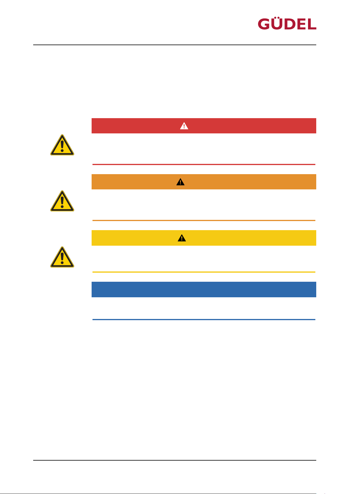
The hazard warnings are defined for the following four types of danger levels:
DANGER
DANGER
DANGER refers to hazards with a high risk of severe physical injury or immediate fatality.
WARNING
WARNING
Safety
WARNING refers to hazards with a moderate risk of severe physical injury
or potential fatality.
CAUTION
CAUTION
CAUTION refers to hazards with a slight risk of moderate physical injury.
NOTE
NOTE
NOTE refers to hazards that can lead to property damage.
72057594178931083_v7.0_EN-US
21
Page 22
OPERATING MANUAL Automatic lubrication system
Safety
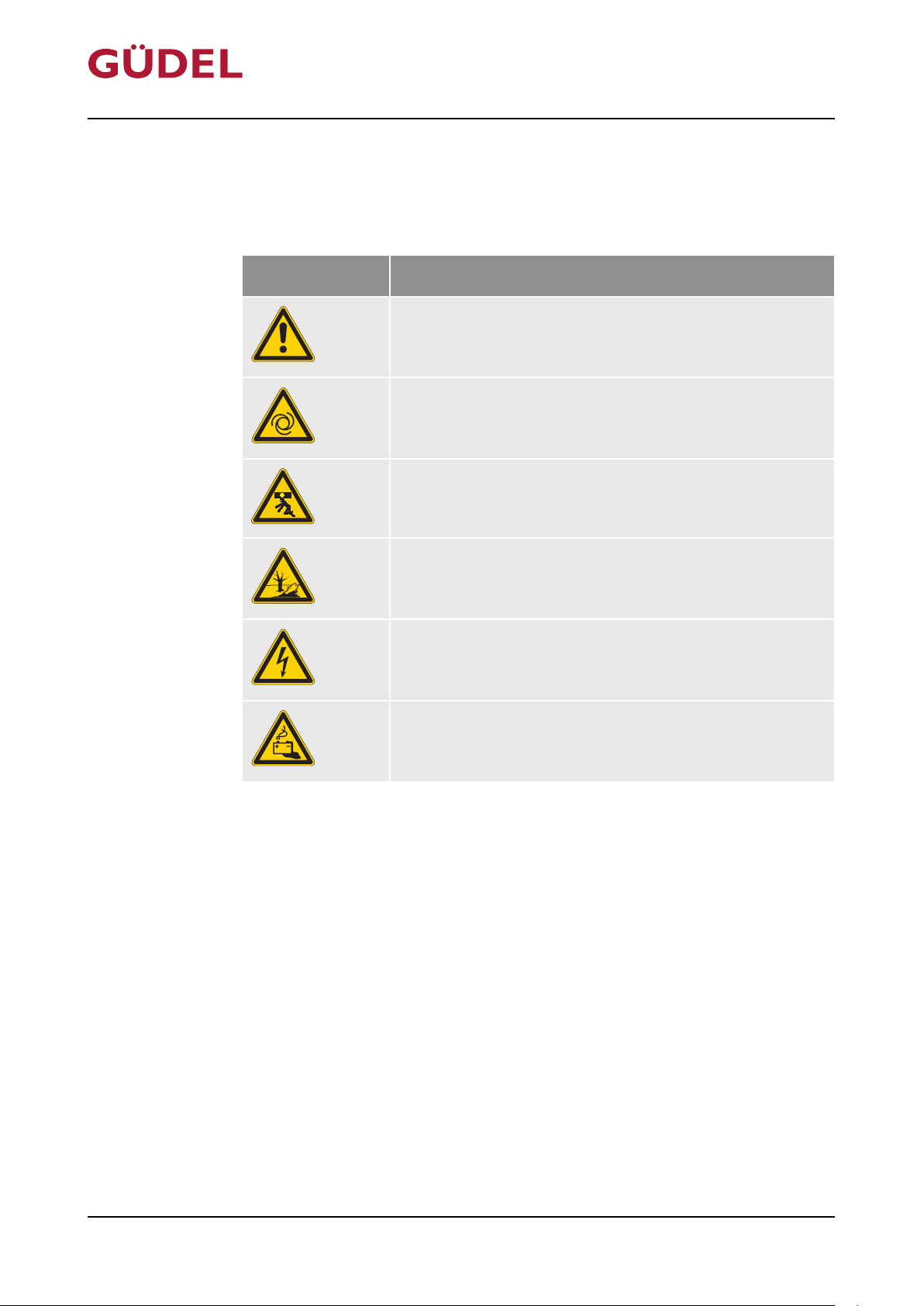
3.2.2 Explanation of warning symbol
Hazard warnings for personal injuries contain the symbol of the corresponding hazard.
Symbol Explanation of symbols
Hazards due to general causes
Hazards resulting from automatic startup
Hazards due to falling axles
FlexxPump 404DLS
Hazards due to environmental pollution
Hazards due to dangerous electrical voltage
Hazards from leaking batteries
72057594178931083_v7.0_EN-US
22
Page 23
OPERATING MANUAL Automatic lubrication system
FlexxPump 404DLS
3.3 Fundamentals of safety
3.3.1 Product-specific hazards
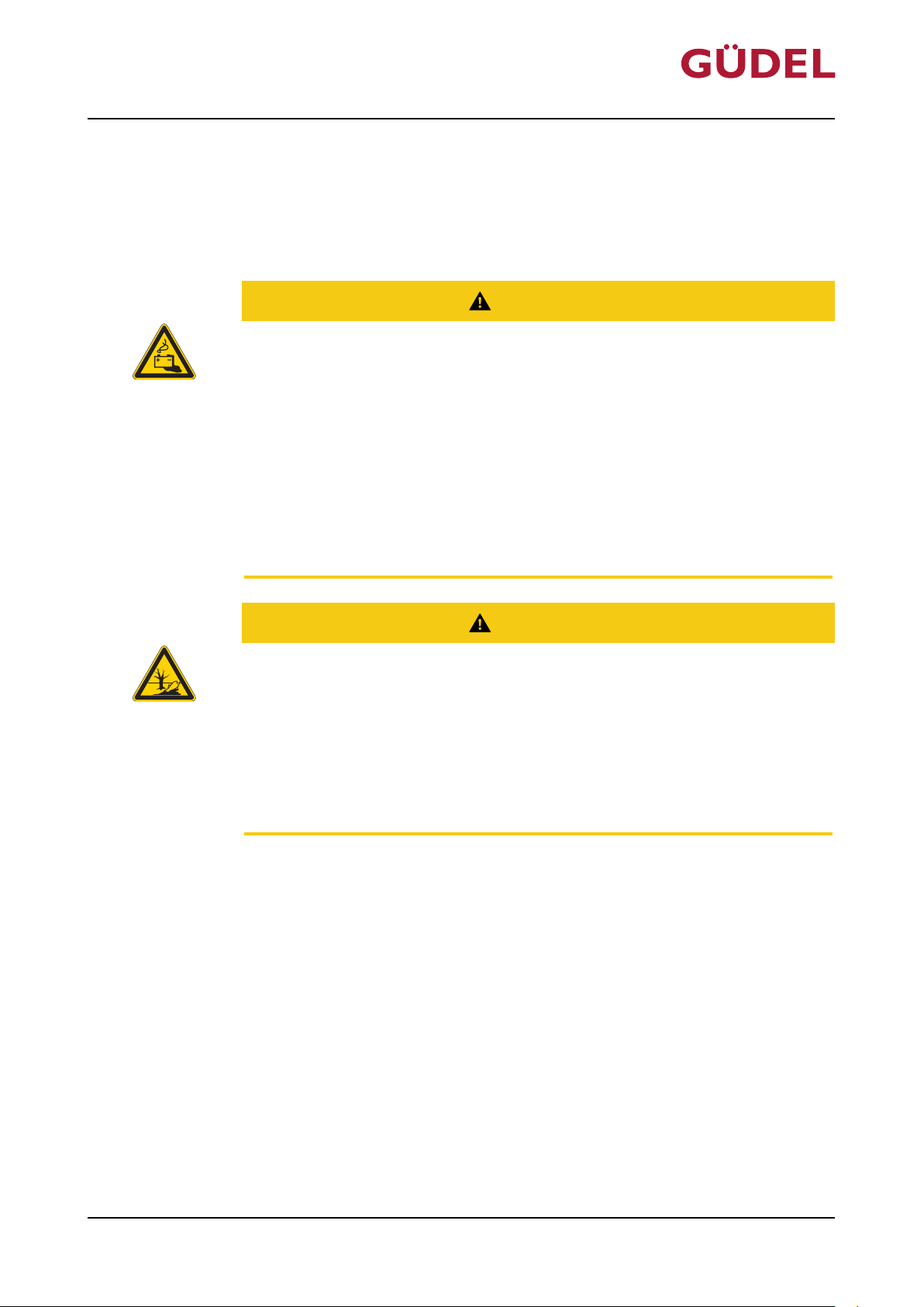
Leaking batteries
Battery fluids and their fumes are hazardous to the environment, corrosive
and poisonous! They cause injury to persons and damage to property!
Observe the following points:
• Make sure there is good ventilation in closed rooms before repairing leaks
• Wear safety goggles and gloves
• Prevent battery fluids from getting into the drinking water supply
• Use only dry cleaning cloths without detergents
Safety
CAUTION
72057594178931083_v7.0_EN-US
• Dispose of batteries in an environmentally friendly manner
CAUTION
Oil, greases
Oils and greases are harmful to the environment!
• The oils and greases must not get into the drinking water supply. Take appropriate measures
• Observe the country-specific safety data sheets
• Oils and greases must be disposed of as hazardous waste, even if the total
quantity is small
23
Page 24
OPERATING MANUAL Automatic lubrication system
Safety
3.3.2 Material safety data sheets (MSDS)
Safety data sheets contain safety information about the materials. They are
country-specific. Safety data sheets are issued, for example, for materials such
as oils, greases, cleaning agents, etc. The operating company is responsible for
obtaining safety data sheets for all materials used.
Safety data sheets can be obtained as follows:
• Suppliers of chemicals usually supply their substances together with safety
data sheets
• Safety data sheets are available on the Internet.
(Enter "msds" and the name of the material in a search engine. Safety information about the material will be displayed.)
Read the safety data sheets carefully. Follow all the instructions. We recommend that you store the safety data sheets for future reference.
FlexxPump 404DLS
The safety data sheet for Güdel H1 can be found in the download area of our
company Web site http://www.gudel.com
24
72057594178931083_v7.0_EN-US
Page 25

OPERATING MANUAL Automatic lubrication system
FlexxPump 404DLS
4 Product description
4.1 Use
4.1.1 Intended use
The automatic lubrication system is designed exclusively for lubricating Güdel
guideways and Güdel gear teeth. Be sure the hydraulic system is installed correctly ÜChapter6.3.3,238
Any other or additional use is not considered to be use in the intended manner. The manufacturer assumes no liability for any resulting damage. All risks
are borne solely by the user.
Product description
4.1.2 Non-intended use
The product is not intended for:
• Lubrication of runners, bearings, or other elements
• Operation in potentially explosive areas
• Lubrication of elements in or on automobiles
• Operation outside of specified performance data
• Operation outside of permissible temperature range
• Using lubricants with properties other than the ones specified
Any use other than the specified intended use will be considered improper
use and is prohibited!
Do not make any modifications to the product.
72057594178931083_v7.0_EN-US
25
Page 26
D003061
www.gudel.com Made in Germany
Artikelnummer 0193906
GÜDEL
A
B
C
D003063
A
B
Product description
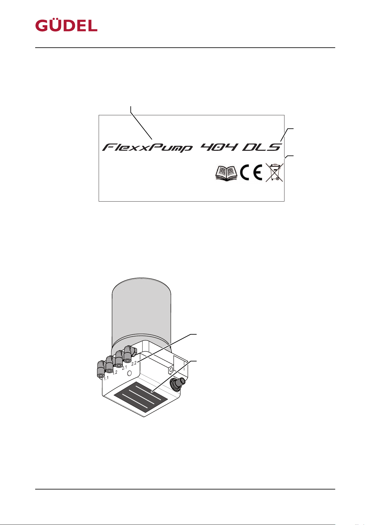
4.2 Product designation
The product has a type plate. It contains the following information:
Fig.4-1 Type plate
OPERATING MANUAL Automatic lubrication system
FlexxPump 404DLS
A Product name
B Pump type
C Item number
The type plate is attached to the bottom of the casing. The hydraulic outputs
are indicated by engraved numbers.
72057594178931083_v7.0_EN-US
Fig.4-2 Product designations
A Numbers of the hydraulic outputs
B Type plate
26
Page 27
D003135
94
110
96
107
112
35,3
196
A
B
OPERATING MANUAL Automatic lubrication system
FlexxPump 404DLS
4.3 Technical data
For specific information on the product, refer to the respective drawings as
well as the documentation on the complete plant.
Product description
Emission sound
pressure level
The emission sound pressure level depends on the machine properties and
the operating conditions. Generally the emissions sound pressure level LpA is
≤ 80dB(A), measured at a distance of 1 m from the safety fence and 1.6 m
above ground level. The measurement is performed according to the ISO
11202 standard. The measured value is time-averaged over a machine specific
cycle and offset with correction factors for room and environment noise correction. The measured value contains measuring uncertainty of +/- 4dB(A)
(accuracy grade 3) and applies for a single machine, measured separately.
4.3.1 FlexxPump
4.3.1.1 Dimensions and connections 404DLS
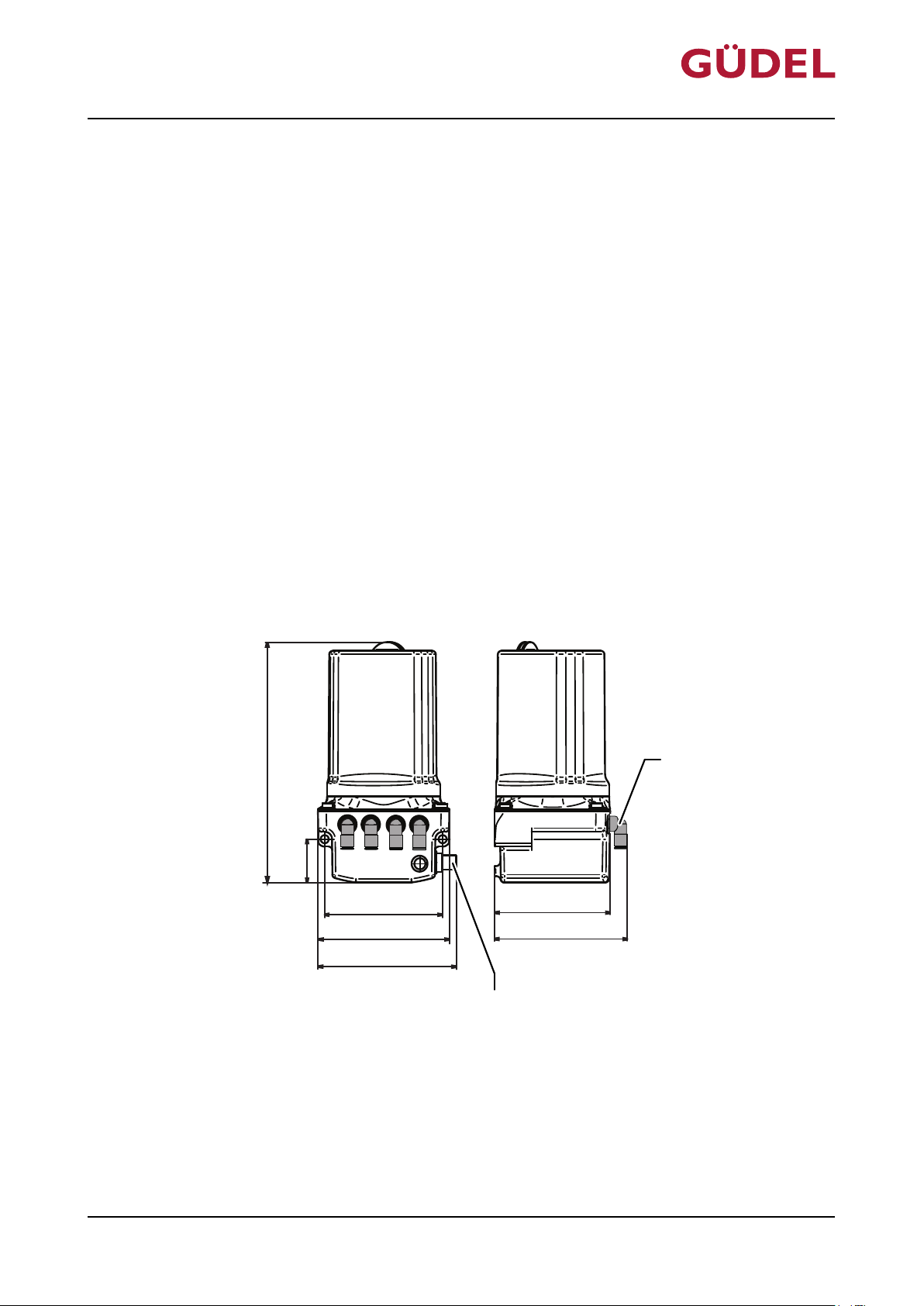
The FlexxPump 404DLS weighs approx. 1500 g and has the following dimensions:
72057594178931083_v7.0_EN-US
Fig.4-3 Dimensions and connections 404DLS
A Hydraulic outputs
B Connection plug M12x1
27
Page 28
Product description
OPERATING MANUAL Automatic lubrication system
FlexxPump 404DLS
Connections
Hydraulic:
• Four connections for hydraulic hoses with diameter of 6/3 mm
Electrical: The four-pole connection size M12x1 transmits the following signals:
• Control signals
• Operating voltage
Interfaces
The FlexxPump 404DLS features an integrated microprocessor. It is controlled via a programmable logic controller (PLC).
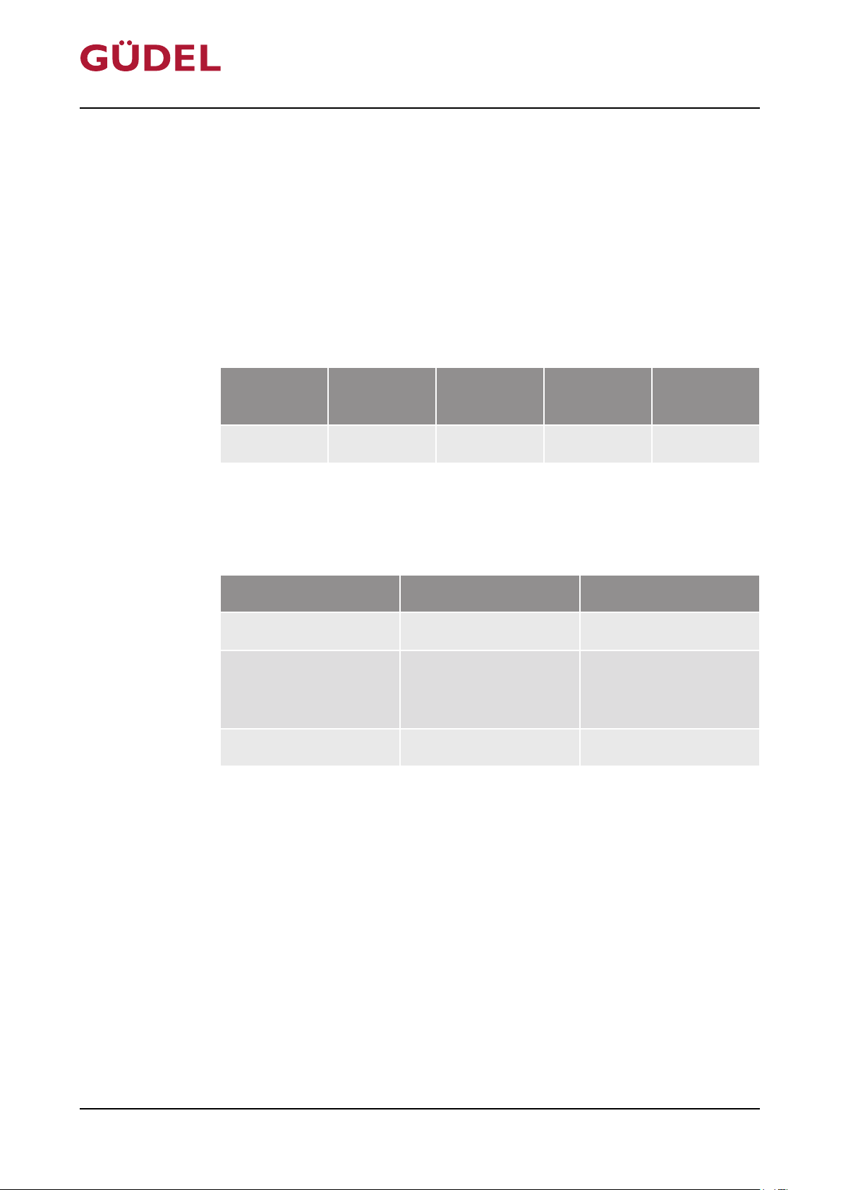
Operating voltage
Operating
voltage
24 V DC 200 mA 350 mA <20 mA 300 mA
Table4-1 Operating voltage
4.3.1.2 Temperature ranges
The following temperature ranges and humidity apply:
Operating
power
Peak
power I
max
Standby
current
Peak output power
Product life phase Temperature range Air humidity
Transport -10 to +60 °C
Operation -20 to +70 °C Up to and at 85 %,
Storage -10 to +40 °C Up to 75 %
Table4-2 Temperature ranges: FlexxPump
4.3.1.3 IP protection class
The product conforms to the protection class IP65.
4.3.1.4 Operating pressure
The operating pressure is 70bar and is monitored electronically by counterpressure measuring. The maximum pressure is 150bar.
condensation formation is not permissible
72057594178931083_v7.0_EN-US
28
Page 29

OPERATING MANUAL Automatic lubrication system
FlexxPump 404DLS
4.3.2 Splitter
4.3.2.1 Temperature ranges
The following temperature ranges and humidity apply:
Product life phase Temperature range Air humidity
Transport -10 to +60 °C
Operation +10 to +80°C Up to and at 85 %,
Storage -10 to +40°C Up to 75 %
Table4-3 Temperature ranges: Splitter
Product description
condensation formation is not permissible
72057594178931083_v7.0_EN-US
4.3.2.2 Accuracy of the lubricant distribution
The accuracy of the lubricant distribution is ±10%. The accuracy is valid up to
a pressure difference of less than 6 bar.
4.3.2.3 Minimum lubrication quantity
Splitters only function correctly if > 0.5 cm3 of lubricant is produced at their
input per lubrication cycle.
4.3.2.4 Maximum pressure
The maximum pressure at the input of splitters is 110 bar.
4.3.3 Lubricant amount
The cartridge contains 400cm3 of lubricant. The empty level is monitored by
an integrated reed contact.
4.3.4 Shelf life of Güdel H1 lubricant
The date of filling of the lubricant is shown on the lubricant cartridge. The
Güdel H1 lubricant has a shelf life of two years from date of filling. This applies to sealed original containers stored under the required storage conditions.
29
Page 30

Product description
OPERATING MANUAL Automatic lubrication system
FlexxPump 404DLS
30
72057594178931083_v7.0_EN-US
Page 31
D003515
A
B
C
E D
OPERATING MANUAL Automatic lubrication system
FlexxPump 404DLS
5 Design, function
5.1 Design
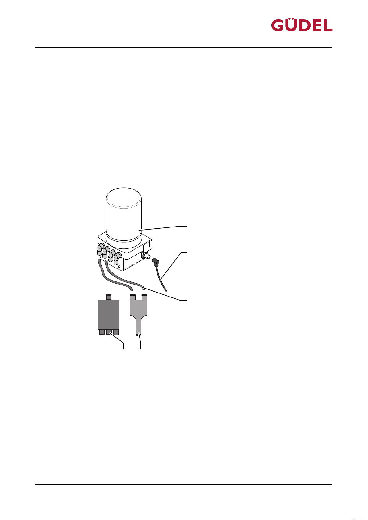
The product consists of the following components:
• FlexxPump
• Splitters or Y-segments
• Hydraulic hoses
• Connecting cable, if necessary
More detailed information ÜChapter6.3.3,238
Design, function
72057594178931083_v7.0_EN-US
Fig.5-1 Design of FlexxPump lubrication system
A FlexxPump D Y-segment (combines lubricants)
B Connecting cable E Splitter (separates lubricants)
C Hydraulic hoses
31
Page 32
D003139
A
B
C
D
E
F
OPERATING MANUAL Automatic lubrication system
Design, function
5.1.1 Detailed design of FlexxPump 404DLS
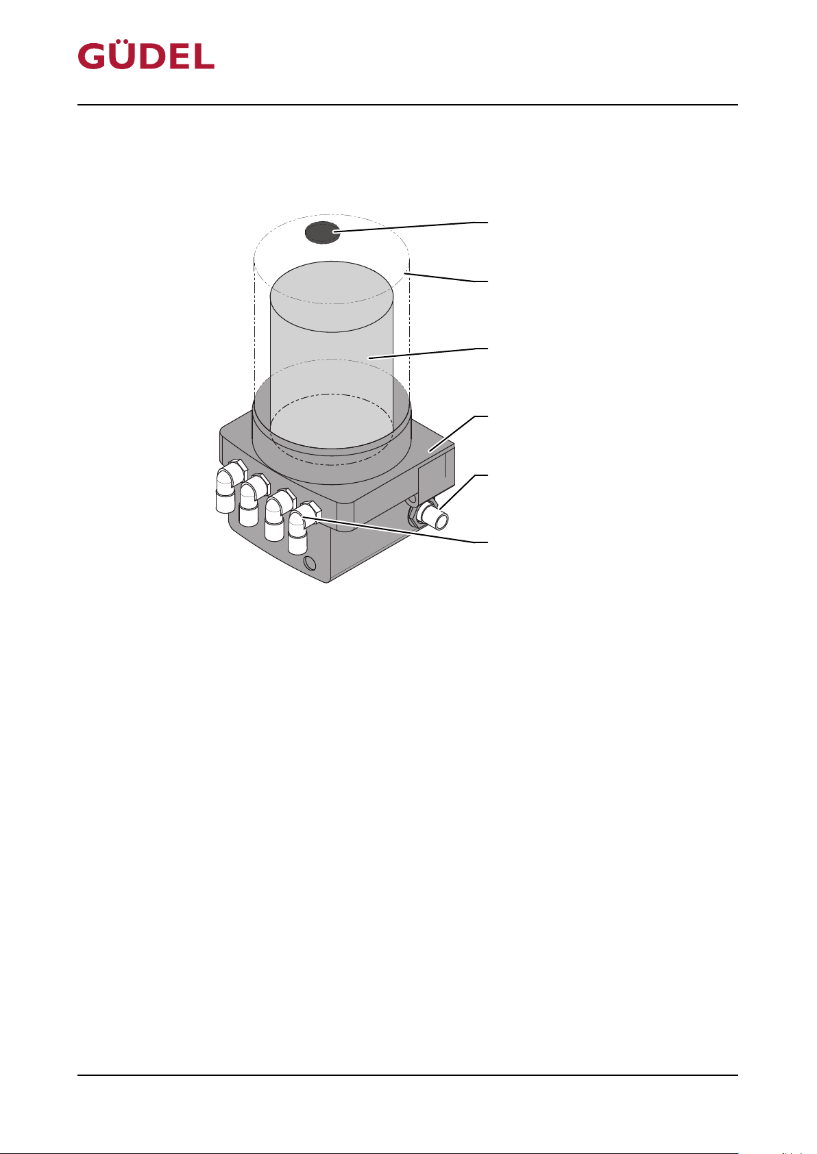
The FlexxPump 404DLS consists of the following elements:
FlexxPump 404DLS
Fig.5-2 Detailed design of FlexxPump 404DLS
A Vent locking mechanism D Casing
B Covering E Connection plug for supply and control
system
C Cartridge F Hydraulic outputs
72057594178931083_v7.0_EN-US
32
Page 33
Lubrication quantity
½ lubrication quantity
½ lubrication quantity
OPERATING MANUAL Automatic lubrication system
FlexxPump 404DLS
5.2 Function
5.2.1 Functional description
The automatic lubrication system is a lubrication system for Güdel components. The FlexxPump feeds the lubricant from the cartridge into the lines.
Depending on the design, the lubricant is distributed through splitters, combined through Y-segments, or distributed directly to the lubrication area.
Rack and pinions are lubricated by lubricating pinions; guideways are lubricated by lubricating elements.
The FlexxPump outputs a signal in case of overpressure, if the cartridge is
empty and for each piston stroke. This makes it possible to process such information further.
5.2.2 FlexxPump
Design, function
72057594178931083_v7.0_EN-US
5.2.2.1 404DLS
A PLC (not included in the scope of delivery) feeds and controls the
FlexxPump. All signals are transmitted to the PLC.
5.2.3 Splitter
5.2.3.1 Function
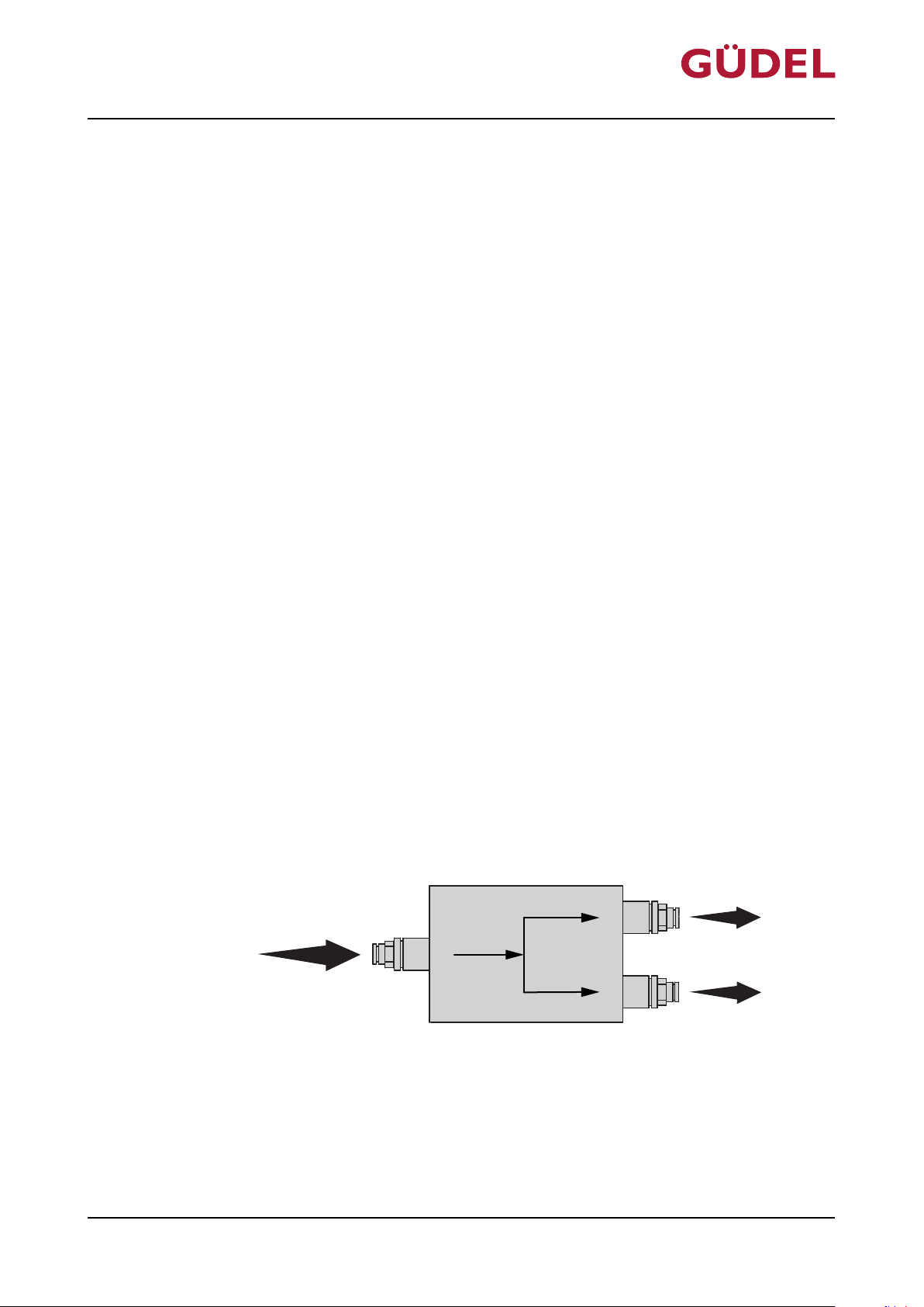
The quantity of lubricant at the input is distributed evenly between the outputs. The splitter only works in the direction of the arrow.
Fig.5-3 Function: Splitter, 2-fold
33
Page 34

Design, function
OPERATING MANUAL Automatic lubrication system
FlexxPump 404DLS
34
72057594178931083_v7.0_EN-US
Page 35
OPERATING MANUAL Automatic lubrication system
FlexxPump 404DLS
6 Commissioning
6.1 Introduction
6.1.1 Safety
Only perform the tasks described in this chapter after you have read and understood the chapter "Safety". Ü215
It concerns your personal safety!
Automatic startup
During work on the product, there is danger of the machine starting up automatically. This can lead to severe or fatal injuries!
Commissioning
WARNING
72057594178931083_v7.0_EN-US
Before working in the danger area:
• Secure vertical axes (if equipped) against falling.
• Switch off the superordinate main power supply. Secure it against being
switched on again (main switch for the complete system)
• Before switching on the system again, make sure that no one is in the danger area
6.1.1.1 Personnel qualifications
Only appropriately trained and authorized technicians are allowed to work on
the product.
6.2 Transport
Avoid strong impacts and shocks while transporting the automatic lubrication
system.
35
Page 36

Commissioning
6.3 Installing
6.3.1 Prerequisites
Dispose of the packaging in accordance with the local waste regulations.
Ü285
OPERATING MANUAL Automatic lubrication system
FlexxPump 404DLS
Checking the deliv-
ery
Interfaces
Table6-1 Interfaces
Assembly site
Check the content of the delivery by comparing it with the accompanying
documents. Check the product for damage. Report transport damage immediately.
Check whether the necessary interfaces exist and are functional. Order information on the connecting cable ÜChapter12,289.
The following interfaces are needed:
Interface 404DLS
Lubricating pinion for gear teeth and
X
Lubricating element for guideway
rail
Connecting cable M12x1, 4-pole
X
with the corresponding length
PLC X
The following prerequisites are made for the assembly site:
36
• Even surface that is at least 107 mm long and 45 mm wide
• Sufficiently rigid
• In order to minimize condensation, the device should not be subjected to
direct sunlight and/or radiation heat
72057594178931083_v7.0_EN-US
Page 37
D003085
A B C
OPERATING MANUAL Automatic lubrication system
FlexxPump 404DLS
6.3.2 Installing the FlexxPump
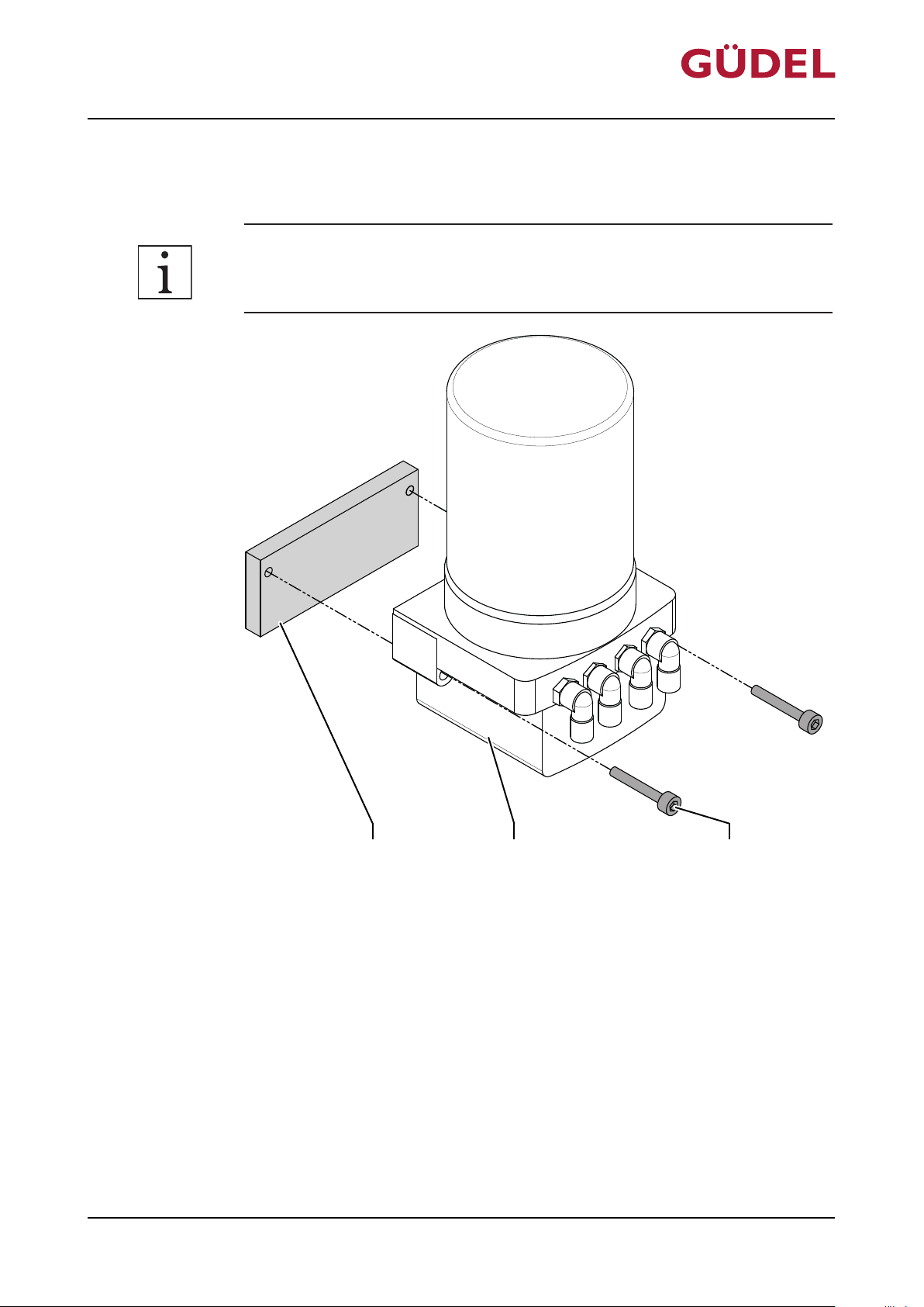
The installation position of the FlexxPump is not important.
Commissioning
72057594178931083_v7.0_EN-US
Fig.6-1 Installing the FlexxPump
A Assembly site
B FlexxPump
C Screw
Assemble the FlexxPump as follows:
1 Mount FlexxPump with two screws M6 L
(tightening torque 5 Nm)
The FlexxPump is assembled.
= 40mm
min
37
Page 38
D003078
A B C
F E D
Commissioning
6.3.3 Connect hydraulics
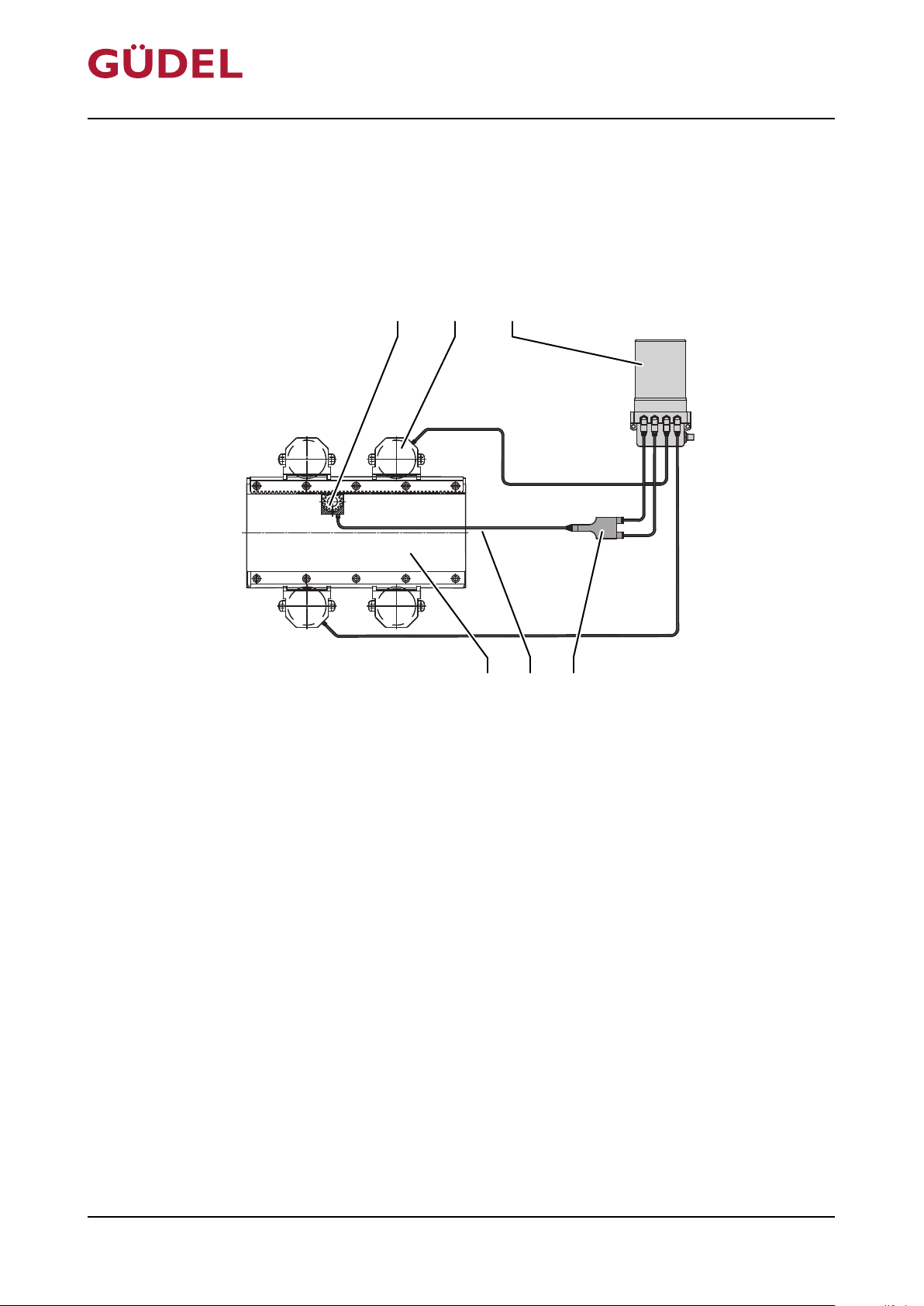
6.3.3.1 404DLS 3-fold
System with 3 lubrication points
OPERATING MANUAL Automatic lubrication system
FlexxPump 404DLS
Fig.6-2 Design 404DLS 3-fold
A Lubricating pinion (not included in the
scope of delivery)
B Lubricating element (not included in the
scope of delivery)
C FlexxPump 404DLS F 1st axle (not included in the scope of de-
D Y-segment
E Hydraulic hose diameter 6/3 mm
livery)
72057594178931083_v7.0_EN-US
38
Page 39
D003080
A B C D
G F E
OPERATING MANUAL Automatic lubrication system
FlexxPump 404DLS
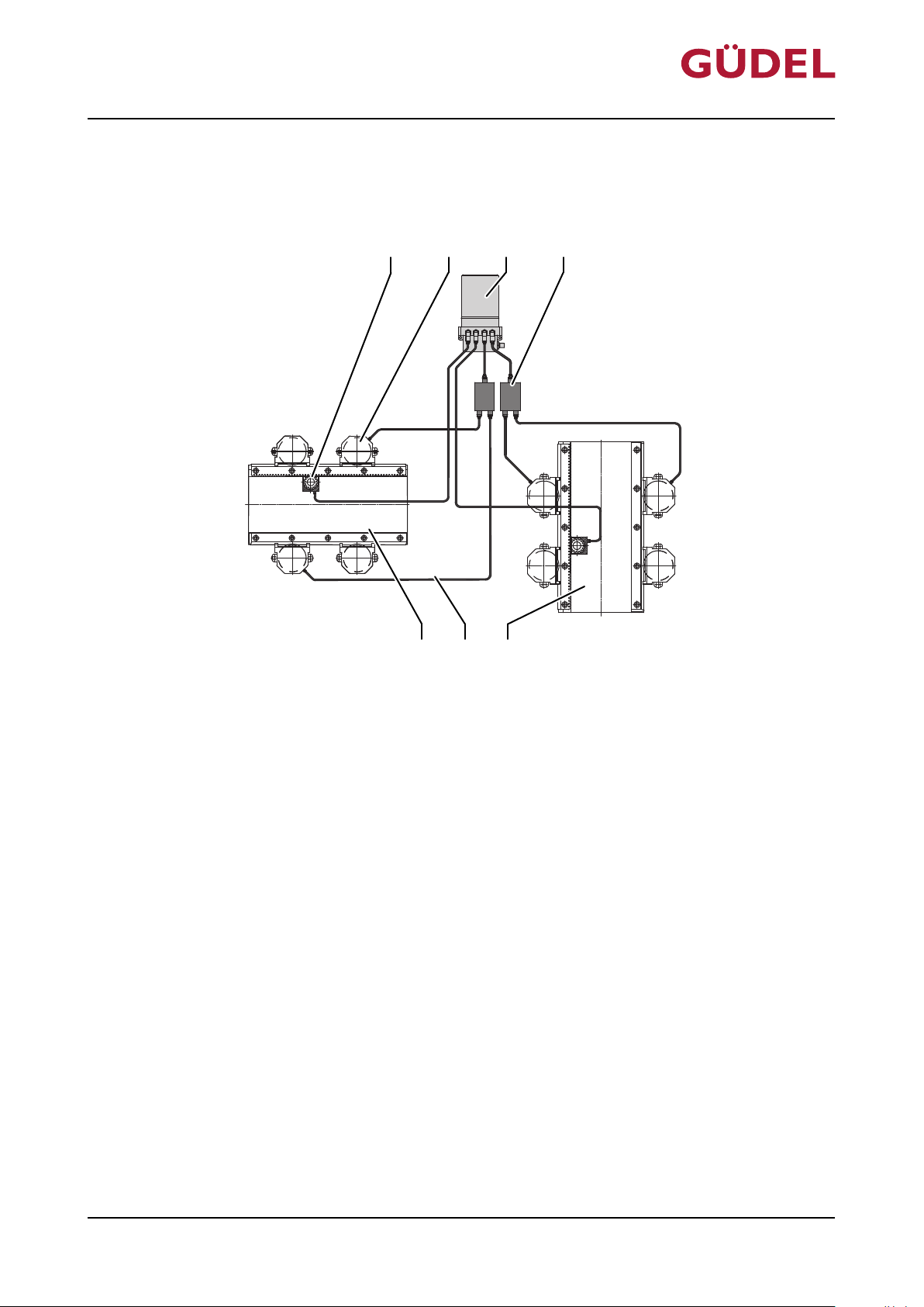
6.3.3.2 404DLS 6-fold
System with 6 lubrication points
Commissioning
72057594178931083_v7.0_EN-US
Fig.6-3 Design 404DLS 6-fold
A Lubricating pinion (not included in the
scope of delivery)
B Lubricating element for guideway rails
(not included in the scope of delivery)
C FlexxPump 404DLS G 1st axle (not included in the scope of de-
D 2x Splitters
E 2nd axle (not included in the scope of
delivery)
F Hydraulic hose diameter 6/3 mm
livery)
39
Page 40
D003081
A B C D E
I H G F
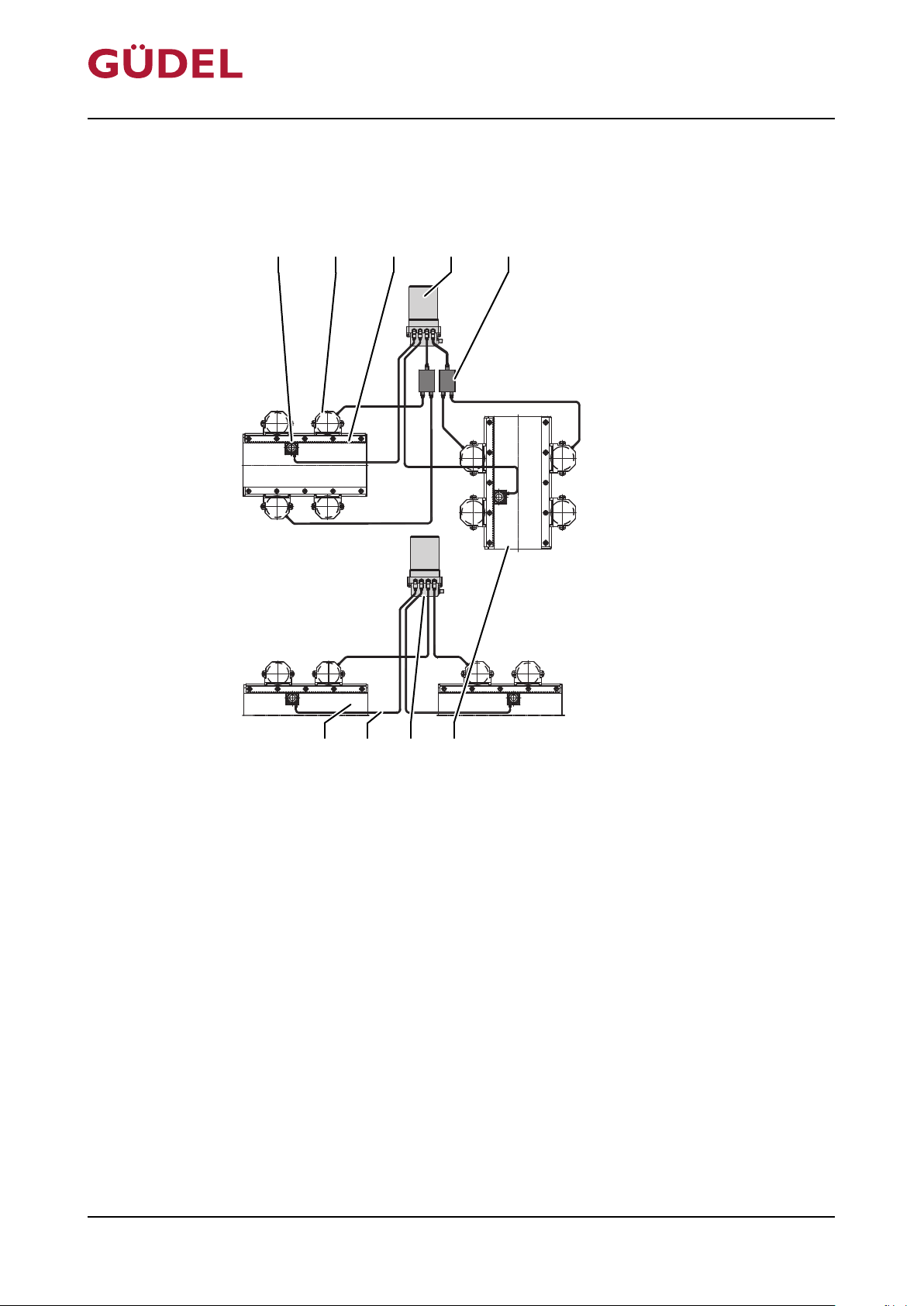
Commissioning
6.3.3.3 404DLS 10-fold
System with 10 lubrication points
OPERATING MANUAL Automatic lubrication system
FlexxPump 404DLS
Fig.6-4 Design 404DLS 10-fold
A Lubricating pinion (not included in the
scope of delivery)
B Lubricating element for guideway rails
(not included in the scope of delivery)
C 1st axle (not included in the scope of de-
livery)
D 1st FlexxPump 404DLS I 3rd axle (not included in the scope of
E 2x Splitters
F 2nd axle (not included in the scope of
delivery)
G 2nd FlexxPump 404DLS
H Hydraulic hose diameter 6/3 mm
delivery)
72057594178931083_v7.0_EN-US
40
Page 41
OPERATING MANUAL Automatic lubrication system
FlexxPump 404DLS
6.3.4 Connecting electrical equipment
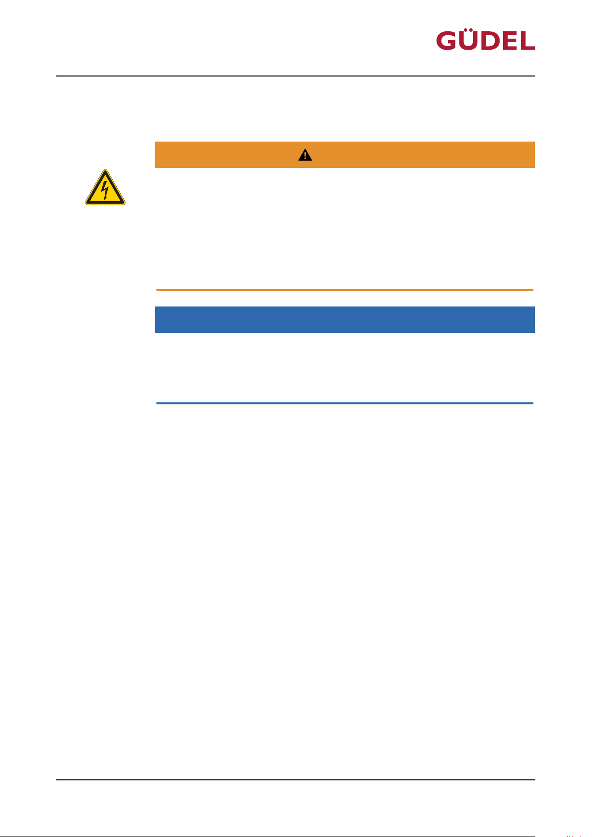
WARNING
Faulty cabling
The available mains voltage (supply voltage) has to match the specifications
on the rating plate. A faultily connected product can cause material damage,
or serious or even fatal injuries.
• Check the deviation of the electrical circuit.
• Use only fuses with specified amperage.
• Wire the plug according to the diagram.
NOTE
Material damage
Commissioning
72057594178931083_v7.0_EN-US
Closing hydraulic outputs creates an overpressure. The overpressure can
cause damage to the product.
• Do not close any hydraulic outputs
41
Page 42
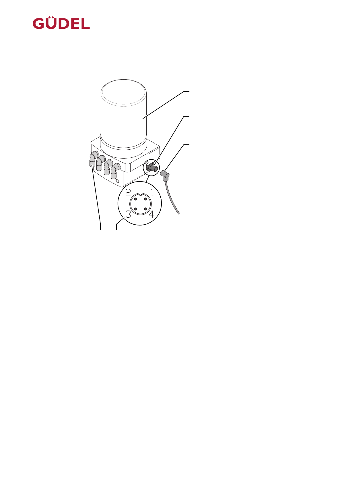
A
B
C
E D
Commissioning
6.3.4.1 Connecting the 404DLS
OPERATING MANUAL Automatic lubrication system
FlexxPump 404DLS
Fig.6-5 Connecting the 404DLS
A FlexxPump 404DLS D Connector pin assignment
B Connection plug for connecting cable E Hydraulic outputs
C Socket of connecting cable
Connect the product as follows:
1 Connect the hydraulic hoses ÜChapter6.3.3,238
2 Screw the connecting cable to the connecting plug
3 Connecting cable
3.1 PIN 1: Input voltage 24 V DC, color: brown
3.2 PIN 2: Control of the individual pump outputs, color: white
3.3 PIN 3: Mass (GND), 0V, color: blue
3.4 PIN 4: Output signal, color: black
The product is connected
72057594178931083_v7.0_EN-US
42
Page 43

OPERATING MANUAL Automatic lubrication system
FlexxPump 404DLS
6.4 Actuate
Commissioning
72057594178931083_v7.0_EN-US
43
Page 44
No
Reset lubrication time/lubrication path
/lubrication cycle
No
Yes
Yes
No
Lubrication not
complete
Warning
Alarm
Check the lubrication
as soon as possible. A
defective lubrication system
can cause damage to the
machine!
Cycle stop
No
Yes
Yes
Reset warning
Control system ON
Lubrication time/
lubrication path
/number of cycles reached?
Start lubrication
Lubrication cycle completed?
Half of the lubrication time/
lubrication path/
number of cycles
reachedt?
Malfunction corrected
and acknowledged?
Commissioning
OPERATING MANUAL Automatic lubrication system
FlexxPump 404DLS
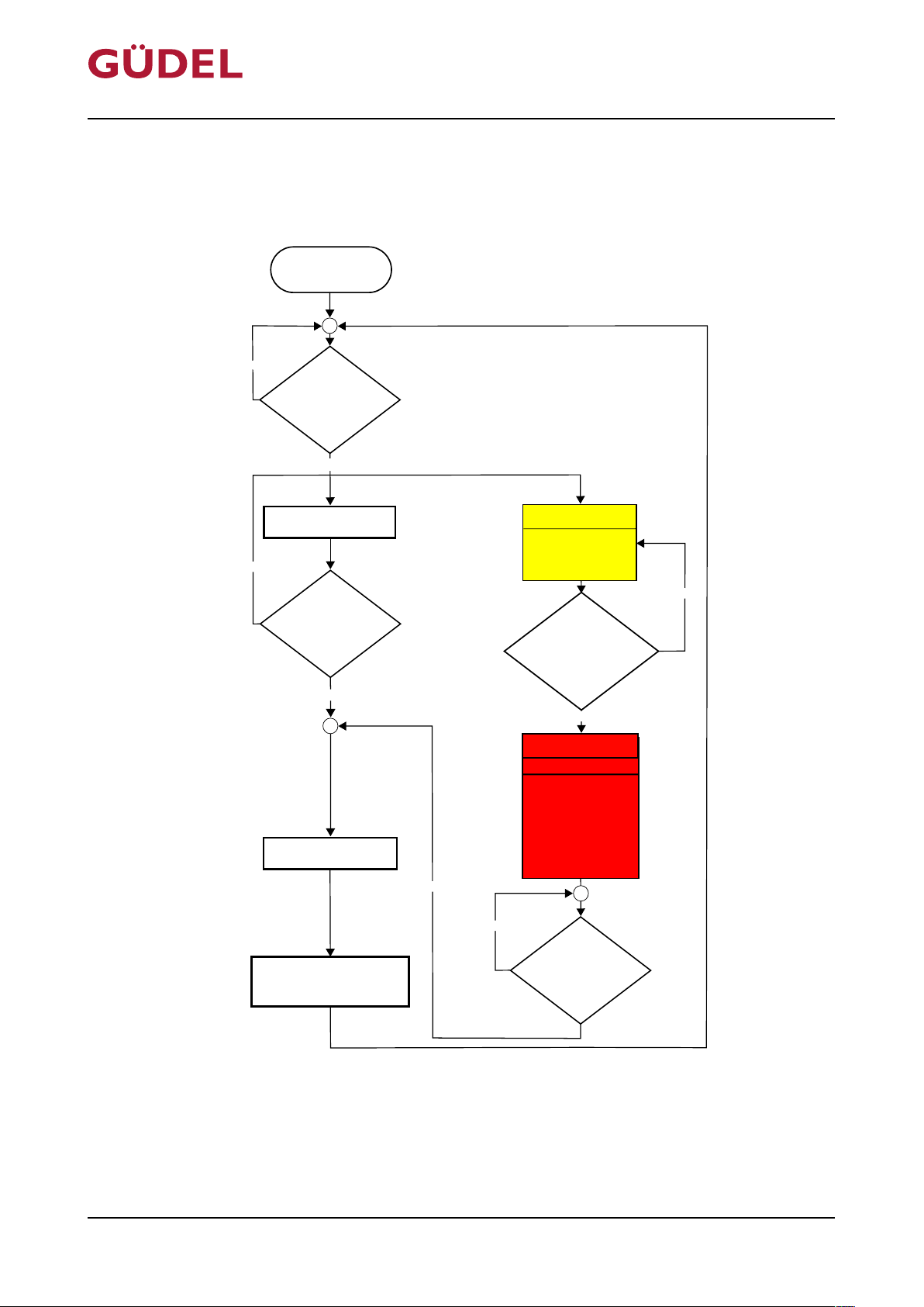
6.4.1 Recommended solution, software programming
Software procedure:
Fig.6-6 Process for automated lubrication
72057594178931083_v7.0_EN-US
44
Page 45
Input signal PIN 1
Output signal PIN 4
U
U
+24 V
(High)
+ 0 V
(Low)
(Low)
+ 0 V
(High)
+24 V
t
t
Hydraulic output
t
V
D003063
D003063
OPERATING MANUAL Automatic lubrication system
FlexxPump 404DLS
Commissioning
6.4.2 Switching the FlexxPump on and off
72057594178931083_v7.0_EN-US
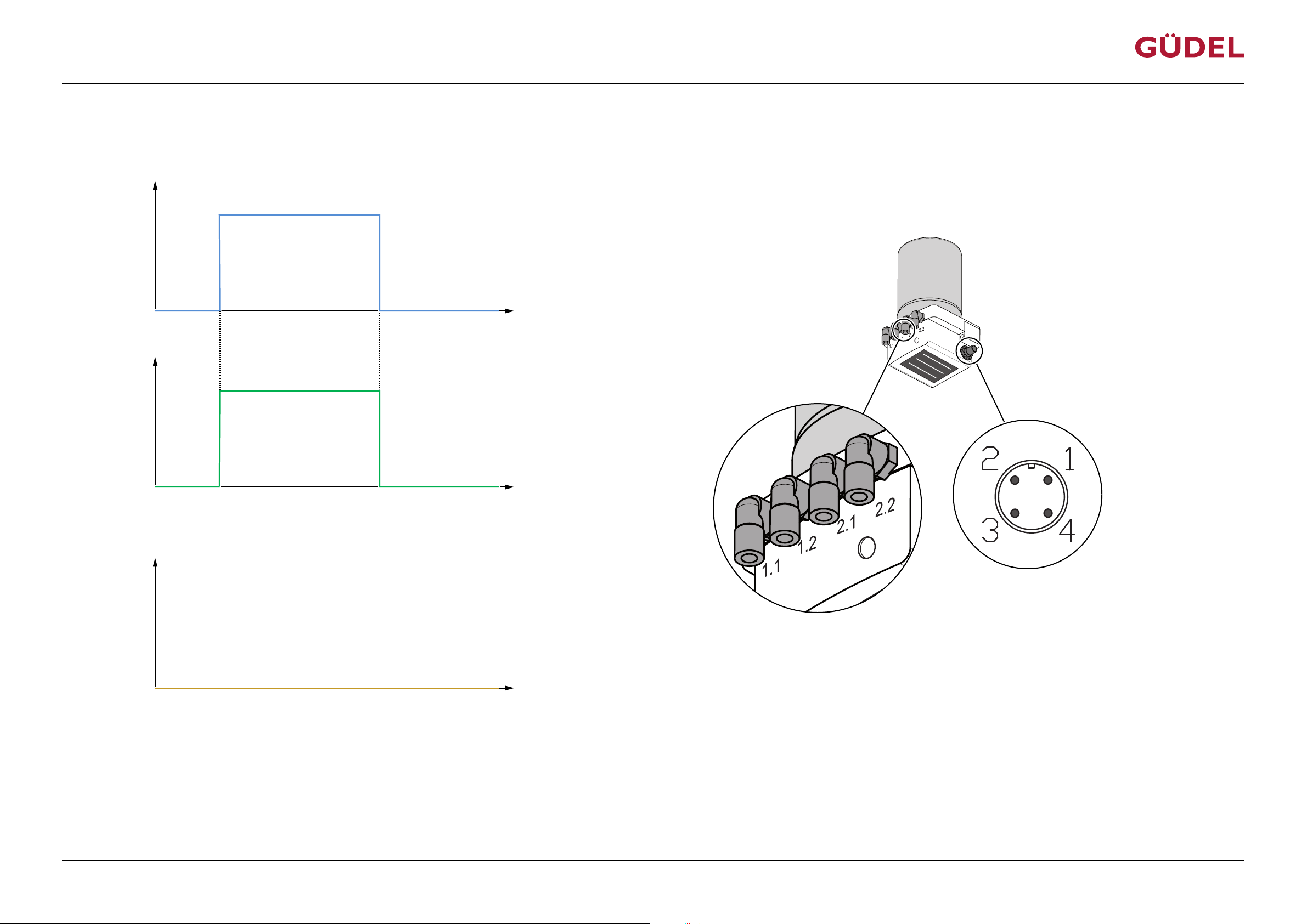
Fig.6-7 Switching time diagram: Switching the FlexxPump on and off
The FlexxPump is switched on as long as a permanent voltage of 24 V DC is applied at PIN 1. Saved information is not lost when the FlexxPump is off. The output signal on PIN 4 is High (20...30V)
during normal operation.
45
Page 46

Commissioning
OPERATING MANUAL Automatic lubrication system
FlexxPump 404DLS
46
72057594178931083_v7.0_EN-US
Page 47
min. 53s
Pause
Input signal PIN 2
Output signal PIN 4
U
U
+24 V
(High)
+ 0 V
(Low)
(Low)
+ 0 V
(High)
+24 V
t
t
8s 8s
3s
1.3s …
1.5s
1.3s …
1.5s
9s …
18s
9s …
18s
9s …
18s
9s …
18s
1.1 or
1.2
2.1 or
2.2
Hydraulic output
2.1 or
2.2
1.1 or
1.2
t
0.15cm30.15cm
3
0.15cm30.15cm
3
V
D003063
D003063
OPERATING MANUAL Automatic lubrication system
FlexxPump 404DLS
6.4.3 Lubrication
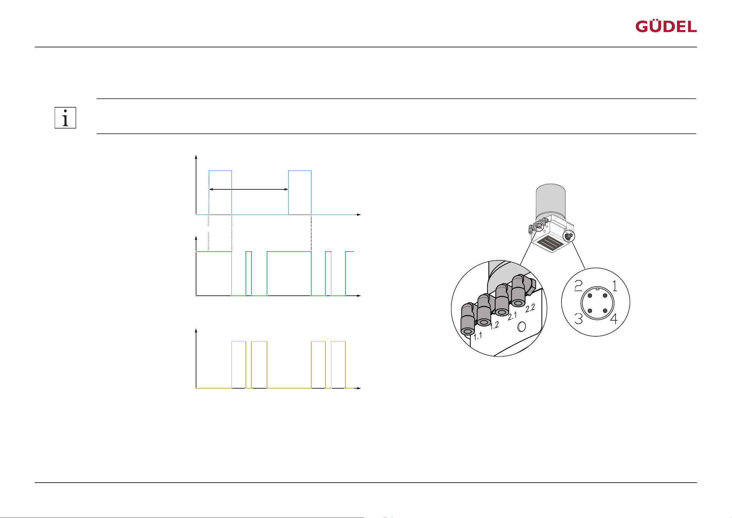
The following signal on PIN 2 causes 0.15 cm3 of lubricant to be dispensed at each of the four hydraulic outputs:
Accuracy of the impulses (High) on PIN 2: +/- 0.2s or +/- 10%!
Commissioning
72057594178931083_v7.0_EN-US
Fig.6-8 Switching time diagram: Normal case
At the displayed signal on PIN 2, all four hydraulic outputs dispense 0.15 cm3 lubricant each. Start of the dispensing = output 1.1 or 1.2, then output 2.1 or 2.2. Each hydraulic output is filled with lubricant by its respective piston. Each piston carries out a lubrication stroke. Per lubrication stroke, 0.15 cm3 lubricant is pumped into the respective hydraulic output. The output signal on PIN 4 is High
(+20...30V) during normal operation. During an actual motor run of the FlexxPump, the signal switches to Low (+0V). Normally this takes between approx. 9 and 18 seconds, depending on the length
of the hydraulic hoses and the viscosity of the lubricant. Afterwards, the signal switches back to High (+24V).
47
Page 48

Commissioning
OPERATING MANUAL Automatic lubrication system
FlexxPump 404DLS
48
72057594178931083_v7.0_EN-US
Page 49
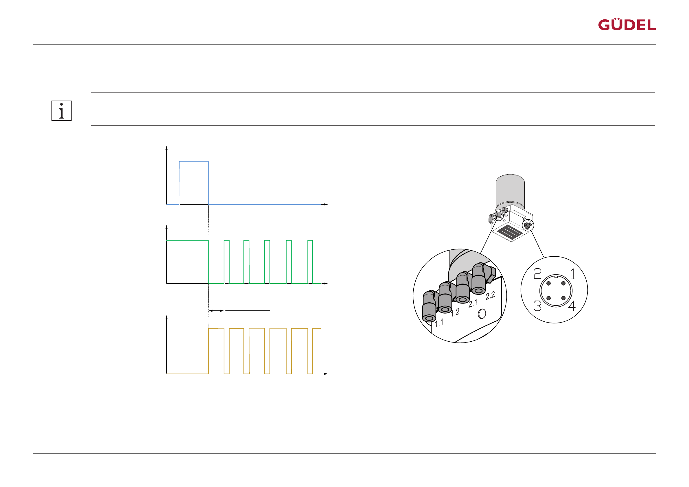
Input signal PIN 2
Output signal PIN 4
U
U
+24 V
(High)
+ 0 V
(Low)
(Low)
+ 0 V
(High)
+24 V
t
t
12s
3s
1.3s …
1.5s
1.3s …
1.5s
9s …
18s
9s …
18s
9s …
18s
9s …
18s
1.1 or
1.2
2.1 or
2.2
Hydraulic output
2.1 or
2.2
1.1 or
1.2
t
0.15cm30.15cm
3
0.15cm
3
0.15cm
3
V
1.3s …
1.5s
1.3s …
1.5s
1.3s …
1.5s
9s …
18s
0.15cm
3
1.1 or
1.2
Repetition 80x
…
…
D003063
D003063
OPERATING MANUAL Automatic lubrication system
FlexxPump 404DLS
6.4.4 Filling hydraulic lines / venting the FlexxPump
The following signal on PIN 2 causes 20 x 0.15 cm3 of lubricant to be dispensed at each of the four hydraulic outputs:
Accuracy of the impulses (High) on PIN 2: +/- 0.2s or +/- 10%!
Commissioning
72057594178931083_v7.0_EN-US
Fig.6-9 Switching time diagram: Filling lines / venting the FlexxPump
The filling process starts with the displayed signal on PIN 2. The filling process takes a maximum of 1600 seconds. The filling process is continued after the FlexxPump is switched on if it was interrupted by switching off the FlexxPump. The output signal on PIN 4 is High (+20...30V) during normal operation. During an actual motor run of the FlexxPump, the signal switches to Low (+0V). Normally this takes between approx. 9 and 18 seconds, depending on the length of the hydraulic hoses and the viscosity of the lubricant. Afterwards, the signal switches back to High (+24V).
49
Page 50

Commissioning
OPERATING MANUAL Automatic lubrication system
FlexxPump 404DLS
50
72057594178931083_v7.0_EN-US
Page 51
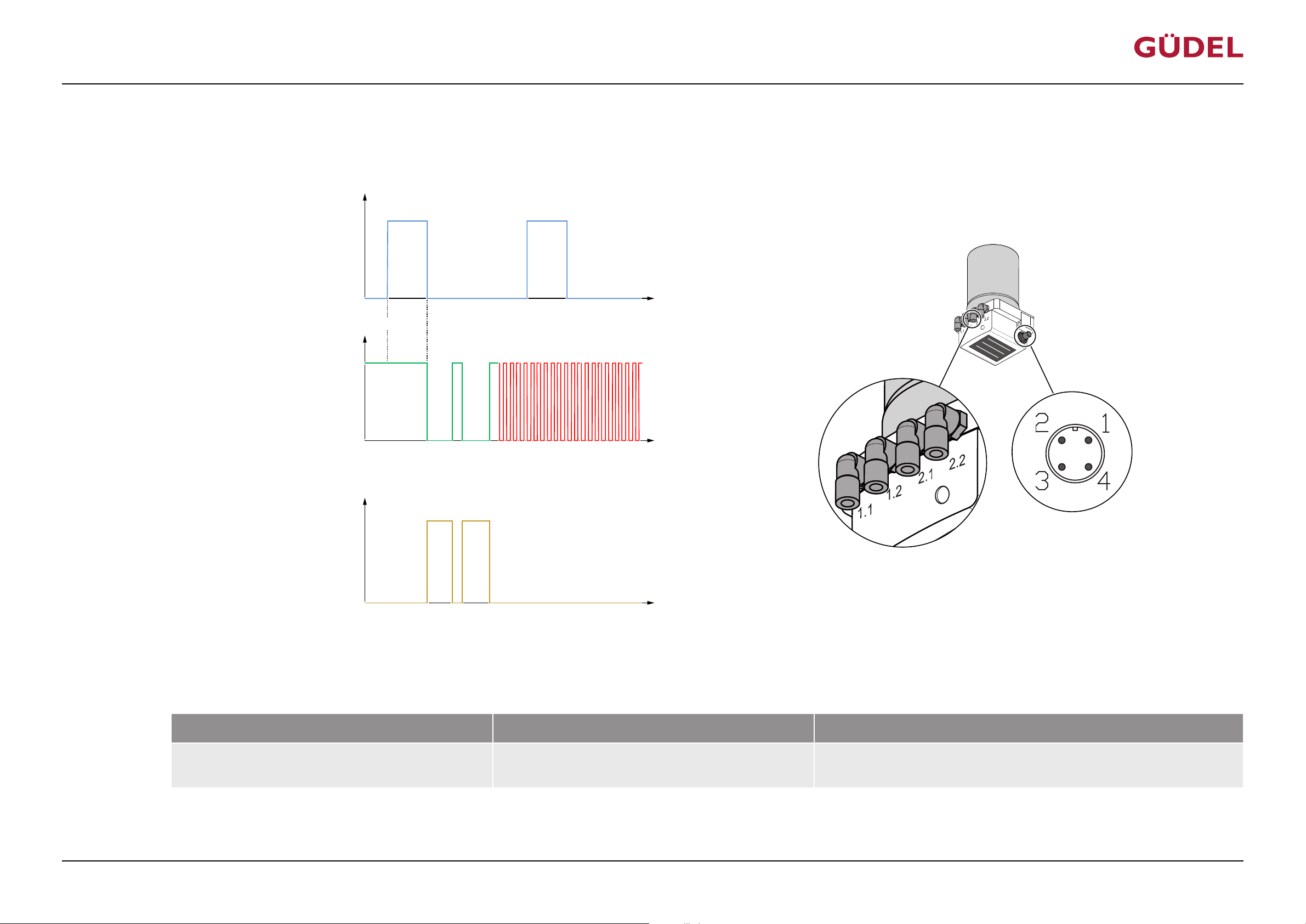
Input signal PIN 2
Output signal PIN 4
U
U
+24 V
(High)
+ 0 V
(Low)
(Low)
+ 0 V
(High)
+24 V
t
t
8s 8s
3s
1.3s …
1.5s
0.5Hz ( 1s High / 1s Low)
9s …
18s
9s …
18s
1.1 or
1.2
2.1 or
2.2
Hydraulic output
t
0.15cm30.15cm
3
V
D003063
D003063
OPERATING MANUAL Automatic lubrication system
FlexxPump 404DLS
6.4.5 Error message: Empty
The FlexxPump issues the following signal on PIN 4 if the lubricant cartridge is empty:
Commissioning
72057594178931083_v7.0_EN-US
Fig.6-10 Switching time diagram: Error message: Empty
If the cartridge is empty, the FlexxPump issues a change signal (rectangular pulse) on PIN 4 between High and Low with a frequency of 0.5 Hz. The output signal on PIN 4 is High (+20...30V) during
normal operation. During an actual motor run of the FlexxPump, the signal switches to Low (+0V). Normally this takes between approx. 9 and 18 seconds, depending on the length of the hydraulic
hoses and the viscosity of the lubricant. Afterwards, the signal switches back to High. You can use the signal change during motor run to calculate the emptying time of the cartridge.
Malfunction Cause Measure
Lubrication system does not lubricate Cartridge missing/empty or air in FlexxPump; pump func-
tion stopped
Insert new cartridge or vent FlexxPump; the pump continues running without
change
Table6-2 Malfunctions / Troubleshooting
51
Page 52

Commissioning
OPERATING MANUAL Automatic lubrication system
FlexxPump 404DLS
52
72057594178931083_v7.0_EN-US
Page 53
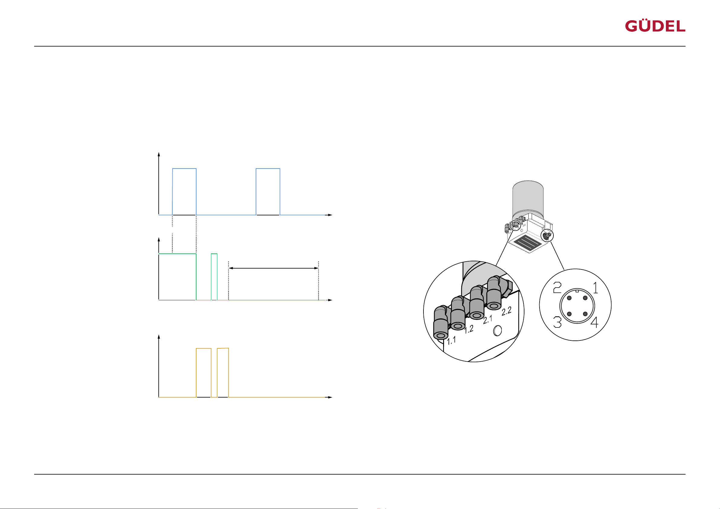
Input signal PIN 2
Output signal PIN 4
U
U
+24 V
(High)
+ 0 V
(Low)
(Low)
+ 0 V
(High)
+24 V
t
t
8s 8s
3s
1.3s …
1.5s
9s …
18s
9s …
18s
1.1 or
1.2
2.1 or
2.2
Hydraulic output
t
0.15cm
3
? cm
3
V
Duration > 30s
D003063
D003063
OPERATING MANUAL Automatic lubrication system
FlexxPump 404DLS
6.4.6 Error message: General
The following non-conclusive causes may lead to a general error message:
• counter-pressure in the hydraulic lines is too high
• destroyed electronic component on PIN 4 due to electrical overcurrent
• internal error in the FlexxPump
If a general error message is active, the FlexxPump issues the following signal on PIN 4:
Commissioning
72057594178931083_v7.0_EN-US
Fig.6-11 Switching time diagram: Error message: General
For blocked hydraulic lines or other errors, the FlexxPump issues a Low (+0V) signal on PIN 4 lasting more than 30 seconds. The output signal on PIN 4 is High (+20...30V) during normal operation.
During an actual motor run of the FlexxPump, the signal switches to Low (+0V). Normally this takes between approx. 9 and 18 seconds, depending on the length of the hydraulic hoses and the viscosity of the lubricant. Afterwards, the signal switches back to High.
53
Page 54
Commissioning
OPERATING MANUAL Automatic lubrication system
FlexxPump 404DLS
Malfunction Cause Measure
Lubrication system does not lubricate The measured counter-pressure was too high three
Lubrication system does not lubricate Various causes • Switch the FlexxPump off and on again. This does not delete the data
Table6-3 Malfunctions / Troubleshooting
times in a row. Hydraulic connections or hoses may be
blocked, hoses too long and/or lubricant too stiff/hard.
Pump function has been stopped.
Remove cause of the counter-pressure, switch the FlexxPump off and on
again. The fault is set to zero. The FlexxPump starts up again.
memory.
• Contact the service department if the problem reoccurs
54
72057594178931083_v7.0_EN-US
Page 55
OPERATING MANUAL Automatic lubrication system
FlexxPump 404DLS
6.4.7 Lubrication recommendation
6.4.7.1 General information
The running surfaces of guideways, racks as well as the drive pinions generally
need to be sufficiently lubricated. A precise recommendation on the lubrication quantity needed cannot be made, because that depends on various factors. The calculations listed here are based on empirical values and lead to
reference values. The lubrication quantity needs to be checked regularly and
needs to be adapted if necessary.
The following non-conclusive factors determine the sufficient lubrication
quantity:
• Kilometers traveled by the axle
• Degree of contamination of the axle
• Power-on time of the entire plant
• Ambient temperature
• Number of lubrication points
• Elements used in the lubrication system
Commissioning
72057594178931083_v7.0_EN-US
Check the guides and racks regularly to make sure there is sufficient lubrication. Perform lubrication work as soon as the first signs of tribocorrosion
(reddish discoloration of the track) are visible.
Güdel recommends to program the HMI user interface so that the operator
of the entire plant can adjust the lubrication quantity to the operating conditions. The operator is always responsible for adequate and properly functioning lubrication.
These recommendations are valid exclusively for systems that are connected
according to the Güdel standard. ÜChapter6.3.3,238
55
Page 56
Commissioning
6.4.7.2 Basics
OPERATING MANUAL Automatic lubrication system
FlexxPump 404DLS
Average lubricant
requirement at a
lubrication point
(U)
The following lubricant quantities should be dispensed at least per lubrication
point. These are empirical values from Güdel. These values can be met only
approximatively due to the number of outputs of the pumps and the installed
splitters.
Size Average lubricant requirement
1-5 0.30 cm3 / 100 km
6-7 0.40 cm3 / 100 km
Table6-4 Average lubricant requirement per lubrication point (U)
Recommended lu-
brication quantity
(Pt)
The recommended lubrication quantity Pt can be found in the following table.
System Size 1-5 Sizes 6-7
3 lubrication points
0.9 cm3 / 100 km 1.2cm3 / 100km
(e.g. EP, TMF, TMO)
6 lubrication points
1.8cm3 / 100km 2.4 cm3 / 100 km
(e.g. ZP)
per lubrication point (U)
4 lubrication points
1.2cm3 / 100km 1.6cm3 / 100km
(e.g. X-axis FP)
Table6-5 Recommended lubrication quantity (Pt)
6.4.7.3 Minimum lubrication quantity
Splitters only function correctly if > 0.5 cm3 of lubricant is produced at their
input per lubrication cycle.
72057594178931083_v7.0_EN-US
56
Page 57
OPERATING MANUAL Automatic lubrication system
FlexxPump 404DLS
6.4.7.4 Calculation formulas
Basically the emptying time of cartridge P1 needs to be determined. With
multiple axles per FlexxPump, the axle most traveled needs to be taken into
consideration for the calculation (on linear gantries, this is typically the Yaxis).
The following specifications of your application are needed:
• Average velocity of the axle (vm) in m/s
• Operation time (t) of the plant per day in hours
• Power-on time (POT) in %
The following values need to be calculated for P1:
Value Formula Unit
Commissioning
Running performance of the
vm x t x POT x 0.036 km/day
axle per day (V)
Recommended lubrication
(V x Pt)/ 100 cm3/day
quantity per day (P)
Emptying time of cartridge
(P1)
Table6-6 Calculation formulas: Emptying time of the cartridge (P1)
Cartridge volume /
(P x 30)
The lubrication quantity calculator will help you determine the corresponding
settings and lubrication quantities for your application. The lubrication quantity calculator can be found in the download area of our company website
http://www.gudel.com
months
72057594178931083_v7.0_EN-US
57
Page 58

Commissioning
OPERATING MANUAL Automatic lubrication system
FlexxPump 404DLS
58
72057594178931083_v7.0_EN-US
Page 59

OPERATING MANUAL Automatic lubrication system
FlexxPump 404DLS
6.5 Initial commissioning
Commissioning
72057594178931083_v7.0_EN-US
59
Page 60

Commissioning
OPERATING MANUAL Automatic lubrication system
FlexxPump 404DLS
60
72057594178931083_v7.0_EN-US
Page 61
Start lubrication check
End
Clean guideways and racks
Lubricate guideways and racks with lubricating spray
(material number 10406825)
Disconnect all hydraulic lines from the pump
Start the pump's lubrication cycle
Does lubricant flow
out at all hydraulic
outputs of the pump?
Connect all hydraulic lines to the hydraulic outputs
of the pump
Fill lines with lubricant, bleed
air from the lines, remove
kinks
Start the pump's lubrication cycle
Expose lubrication point Remount lubrication point
Yes
No
Hydraulic line filled;
without air bubbles and
kinks?
Yes
No
Check the pumps voltage
supply and function and
correct if necessary
Replace lubricating element /
lubricating pinion if necessary,
then prelubricate
Lubricating element /
lubricating pinion
saturated with
lubricant and intact?
Yes
No
Does lubricant flow
out at lubrication
point?
Yes
No
Other lubrication
points available?
Yes
No
Start lubrication point check
I
II
III
IV
VI
V
VII
VIII
IX
X
XI
XII
OPERATING MANUAL Automatic lubrication system
FlexxPump 404DLS
6.5.1 Carrying out a lubrication check
Commissioning
72057594178931083_v7.0_EN-US
61
Page 62
ü
û
I II III
Commissioning
OPERATING MANUAL Automatic lubrication system
FlexxPump 404DLS
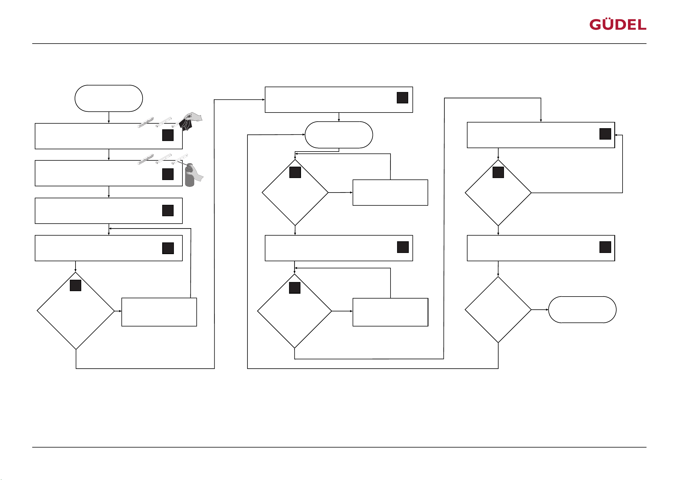
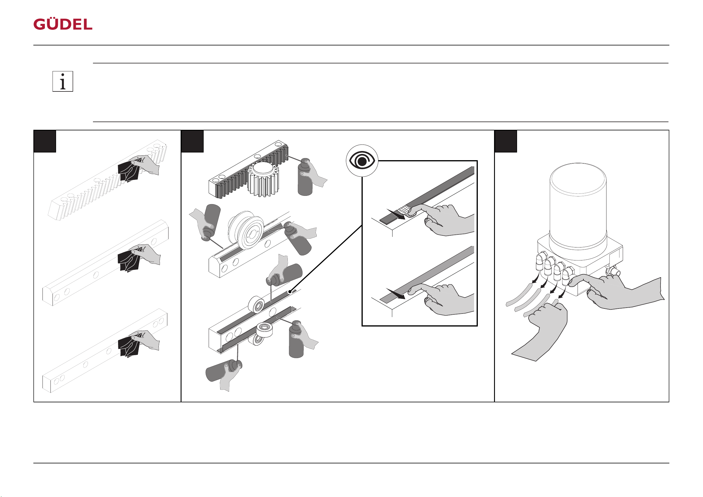
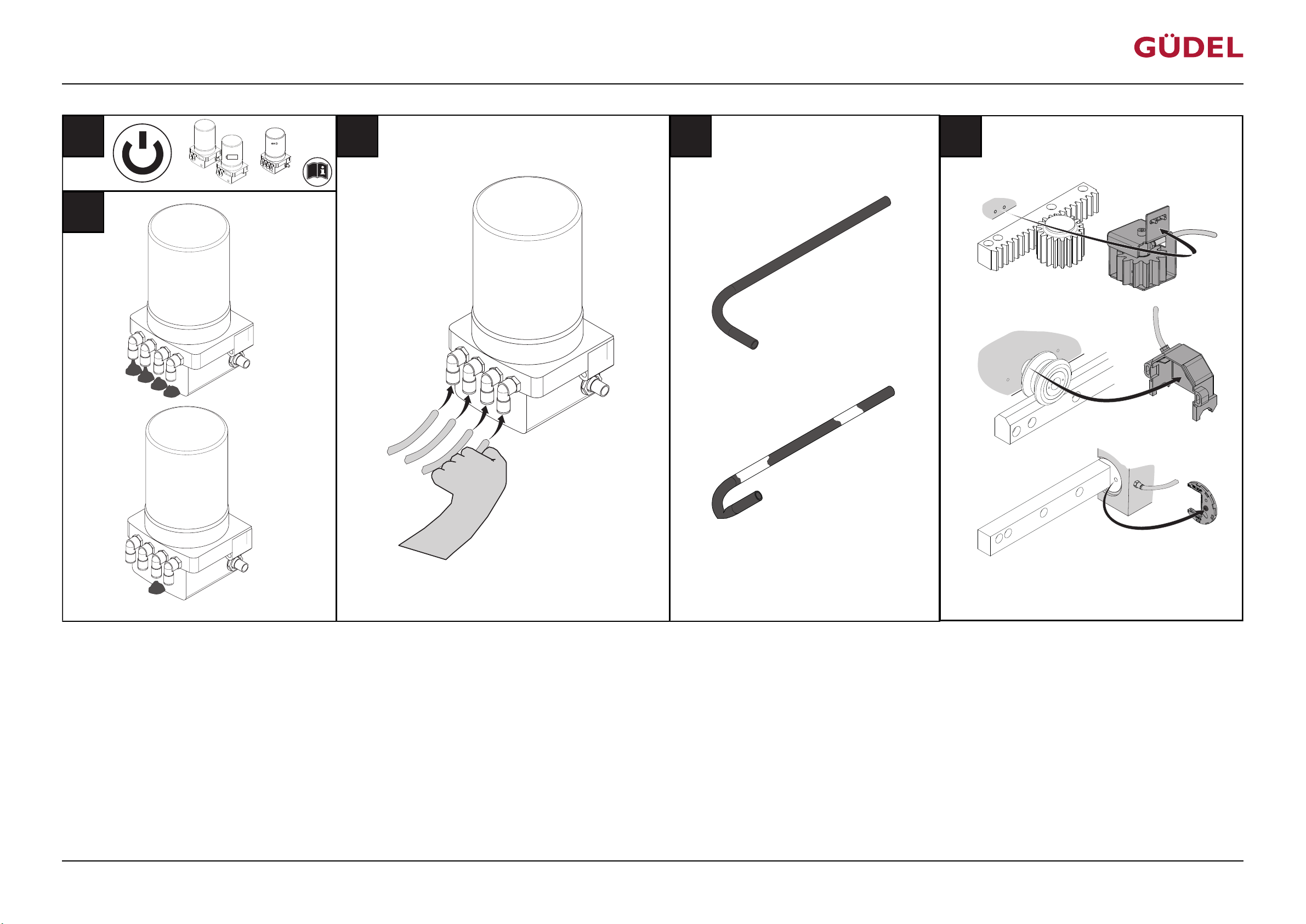
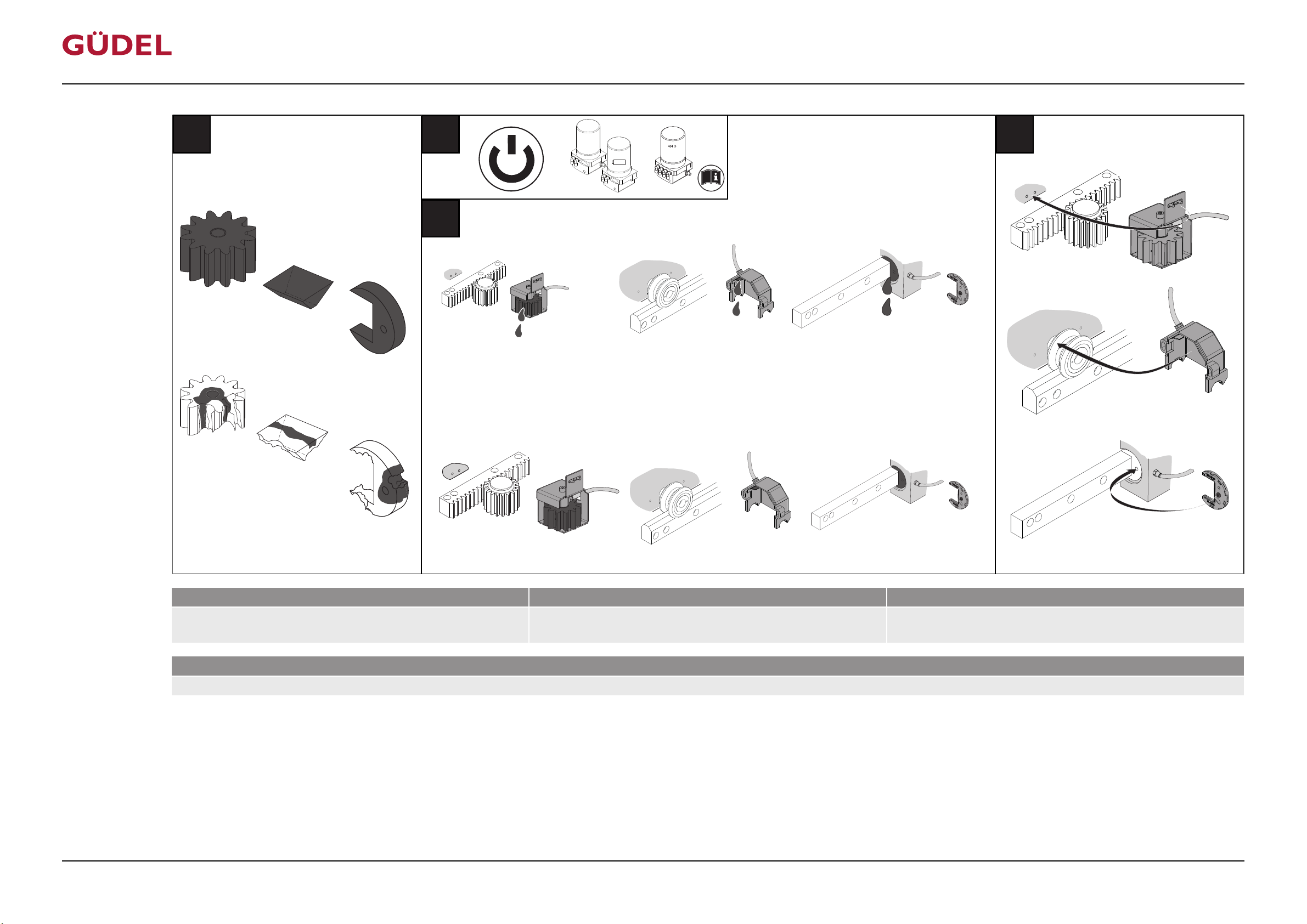
• Carry out this lubrication check as the operator during the commissioning and after down times of more than 4 weeks. The operator is in any case responsible for adequate and properly functioning lubrication.
• Carry out this lubrication check every 2'250 (6'750) operating hours when operating the product at 100% POT (40% POT).
• In case of downtimes of less than 4 weeks before commissioning, as a minimum check the lubricating film on guideways and racks (II) and the hydraulic lines for air bubbles and kinks (VII). If necessary, carry out the complete lubrication check.
72057594178931083_v7.0_EN-US
62
Page 63
IV VI VII
V
ü
û
ü
û
VIII
404 DLS
402
402 B
+
_
OPERATING MANUAL Automatic lubrication system
FlexxPump 404DLS
Commissioning
72057594178931083_v7.0_EN-US
63
Page 64
IX X
XI
ü
û
ü
û
XII
404 DLS
402
402 B
+
_
Commissioning
OPERATING MANUAL Automatic lubrication system
FlexxPump 404DLS
Lubrication ex works Specification Lubrication quantity
Elkalub FLC 8 H1 Cannot be determined Running surfaces of the roller and pinion need to be covered
Cleaning agents
mild universal cleaner free from aromatic compounds (e.g. Motorex OPAL 5000)
Table6-7 Lubricants, Cleaning agents: Prelubricate guideways and racks
completely by a lubricating film
72057594178931083_v7.0_EN-US
64
Page 65

OPERATING MANUAL Automatic lubrication system
FlexxPump 404DLS
Check the connections of the hydraulic system before starting up the product.
Commissioning
72057594178931083_v7.0_EN-US
65
Page 66
Operation
7 Operation
7.1 General
Only operate the product after observing the installation instructions.
For information on operating the product, refer to the appropriate chapter of
the documentation for the complete system.
7.2 Personnel
Training of operating personnel
OPERATING MANUAL Automatic lubrication system
FlexxPump 404DLS
WARNING
Incorrect behavior of untrained, or insufficiently trained, operating personnel
can lead to severe injury or damage to property!
Before the operating personnel begin working with the product:
• Train and instruct the operating personnel
• Point out dangers in the work area to the operating personnel
• Check the qualifications of operating personnel before approving them
• Keep the operating personnel up-to-date in regard to best practices.
Also inform them about technical progress, modifications, etc.
ð If these measures are not complied with, you alone as the operating
company are liable for damages that may result!
66
72057594178931083_v7.0_EN-US
Page 67
OPERATING MANUAL Automatic lubrication system
FlexxPump 404DLS
7.3 Safety
Only perform the tasks described in this chapter after you have read and understood the chapter "Safety". Ü215
It concerns your personal safety!
Automatic startup
During work on the product, there is danger of the machine starting up automatically. This can lead to severe or fatal injuries!
Before working in the danger area:
• Secure vertical axes (if equipped) against falling.
• Switch off the superordinate main power supply. Secure it against being
switched on again (main switch for the complete system)
Operation
WARNING
• Before switching on the system again, make sure that no one is in the danger area
72057594178931083_v7.0_EN-US
67
Page 68

Operation
OPERATING MANUAL Automatic lubrication system
FlexxPump 404DLS
68
72057594178931083_v7.0_EN-US
Page 69
OPERATING MANUAL Automatic lubrication system
FlexxPump 404DLS
8 Maintenance
8.1 Introduction
Maintenance
Work sequences
Original spare
parts
8.1.1 Safety
Perform the work sequences in the order described. Perform the described
tasks at the specified times. This ensures a long service life for your product.
Only use original spare parts. Ü291
Only perform the tasks described in this chapter after you have read and understood the chapter "Safety". Ü215
It concerns your personal safety!
WARNING
Automatic startup
During work on the product, there is danger of the machine starting up automatically. This can lead to severe or fatal injuries!
Before working in the danger area:
• Secure vertical axes (if equipped) against falling.
• Switch off the superordinate main power supply. Secure it against being
switched on again (main switch for the complete system)
72057594178931083_v7.0_EN-US
• Before switching on the system again, make sure that no one is in the danger area
8.1.2 Personnel qualifications
Only appropriately trained and authorized technicians are allowed to work on
the product.
69
Page 70
OPERATING MANUAL Automatic lubrication system
Maintenance
8.2 Consumables and auxiliary agents
8.2.1 Cleaning agents
Use a soft rag or cloth for cleaning tasks. Only use permissible cleaning
agents.
8.2.1.1 Table of cleaning agents
Cleaning agents Location of application
FlexxPump 404DLS
mild universal cleaner free from aromatic compounds (e.g. Motorex
OPAL 5000)
This table does not purport to be exhaustive.
Table8-1 Table of cleaning agents
8.2.2 Lubricants
Unsuitable lubricants
Using unsuitable lubricants can cause damage to the machine!
• Only use the lubricants listed
• If uncertain, please contact our service departments
For more information on the lubricants, refer to the tables below. For further
information, refer to the chapter "Maintenance tasks" and the respective third
party documentation.
Automatic lubrication system: Pump,
lines, other components
Prelubricate guideways and racks
NOTE
Special Güdel lu-
bricants
Alternative manu-
facturers
Low tempera-
tures / food grade
70
If special lubricants have been delivered ex-works at the request of the customer, you can find the relevant specifications in the spare parts list.
The following tables show the specifications of the lubricants. Please inform
your manufacturer accordingly. They will then suggest an alternative from
their product range.
Observe the application range limits of lubricants according to the safety data
sheet.
72057594178931083_v7.0_EN-US
Page 71
OPERATING MANUAL Automatic lubrication system
FlexxPump 404DLS
8.2.2.1 Lubrication
Automatic lubrication system
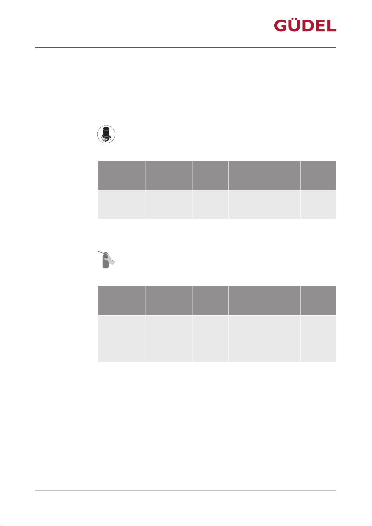
The following lubrication systems and lubricants are provided for the automatic lubrication of the product:
Fig.8-1 Automatic lubrication system FlexxPump
Maintenance
Lubrication
ex works
Specification
Lubrication
quantity
Güdel H1
NSF
cannot be
found
no.146621
Table8-2 Lubricants: Automatic lubrication system FlexxPump
Fig.8-2 Automatic lubrication system FlexxPump
Lubrication
ex works
Specification
Lubrication
quantity
Elkalub FLC
8 H1
Cannot be
determined
Location of application
Automatic lubrication system
FlexxPump
Location of application
Automatic lubrication system
FlexxPump: Prelubricate guideways and
racks
Category
oil
Category
Oil
72057594178931083_v7.0_EN-US
Table8-3 Lubricants: Automatic lubrication system FlexxPump: Prelubricate guideways and racks
71
Page 72

Maintenance
8.2.2.2 Lubricant table
OPERATING MANUAL Automatic lubrication system
FlexxPump 404DLS
Lubrication
ex works
Elkalub FLC
8 H1
Güdel H1
NSF
no.146621
This table does not purport to be exhaustive.
Table8-4 Lubricant table
Specification
Cannot be
determined
cannot be
found
Lubrication
quantity
Location of application
Automatic lubrication system
FlexxPump: Prelubricate guideways and
racks
Automatic lubrication system
FlexxPump
Category
Oil
oil
72
72057594178931083_v7.0_EN-US
Page 73
OPERATING MANUAL Automatic lubrication system
FlexxPump 404DLS
8.3 Maintenance tasks
8.3.1 Checking automatic lubrication system
Check the automatic lubrication system in accordance with the following table.
Maintenance
Inspection
point
Contamination Check the components
Loss of lubricant Check system and its
Function Check function Replace defective compo-
Table8-5 Inspection table
Description Measures
Immediately clean away any
for contamination:
contamination
• Pump
• Lines
• other components
• Remove puddles of oil
surroundings for traces:
• Puddles of oil and oil
spills on the floor or
in the drip sheets
and oil spills on the floor
or in the drip sheets
• Replace defective and
pinched lines
• Leaks, torn or
pinched lines
nents immediately
72057594178931083_v7.0_EN-US
Check the guides and racks regularly to make sure there is sufficient lubrication. Perform lubrication work as soon as the first signs of tribocorrosion
(reddish discoloration of the track) are visible.
73
Page 74
Maintenance
8.3.2 Replacing the cartridge
Replace the cartridge if the malfunction message "Empty" appears.
Switch on or off pump type 404DLS via PLC.
Residual amounts in empty cartridges
Empty cartridges contain lubricant residues. Oils and greases are harmful to
the environment!
• Dispose of the cartridge in an environmentally friendly manner Ü285
Danger from spring tension
OPERATING MANUAL Automatic lubrication system
FlexxPump 404DLS
CAUTION
CAUTION
The covering contains a spring with tension. The covering jumps up when
opened. This can lead to minor injuries!
Make sure that no extremities are in the danger area. Carefully remove the
covering.
Use only original Güdel cartridges. Never refill the cartridges.
74
72057594178931083_v7.0_EN-US
Page 75
D003502
A B C
D
E
OPERATING MANUAL Automatic lubrication system
FlexxPump 404DLS
Maintenance
72057594178931083_v7.0_EN-US
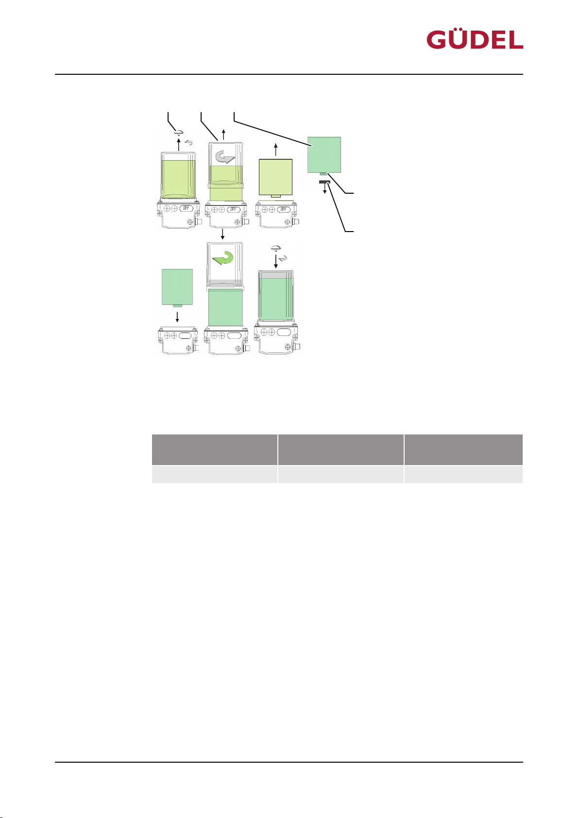
Fig.8-3 Replacing the cartridge
A Vent locking mechanism D O-ring
B Cartridge E Retaining covering
C Covering
Lubrication ex works Specification Lubrication quan-
ÜChapter8.2.2.1, 271 ÜChapter8.2.2.1, 271 400 cm³
Table8-6 Lubricants: Automatic lubrication system FlexxPump
Replace the cartridge as follows:
1 Remove the vent locking mechanism in the direction of the arrow
2 Switch off FlexxPump
3 Remove the covering by turning in the direction of the arrow
4 Remove empty cartridge
5 Remove the retaining covering from the new cartridge
6 Lubricate the O-ring slightly
7 Insert new cartridge (make sure the cartridge fits in properly)
tity
8 Put on the covering and turn hand-tight in the direction of the arrow
9 Switch on the FlexxPump
10 Insert vent locking mechanism and secure
The cartridge is replaced.
75
Page 76

Maintenance
OPERATING MANUAL Automatic lubrication system
FlexxPump 404DLS
76
72057594178931083_v7.0_EN-US
Page 77
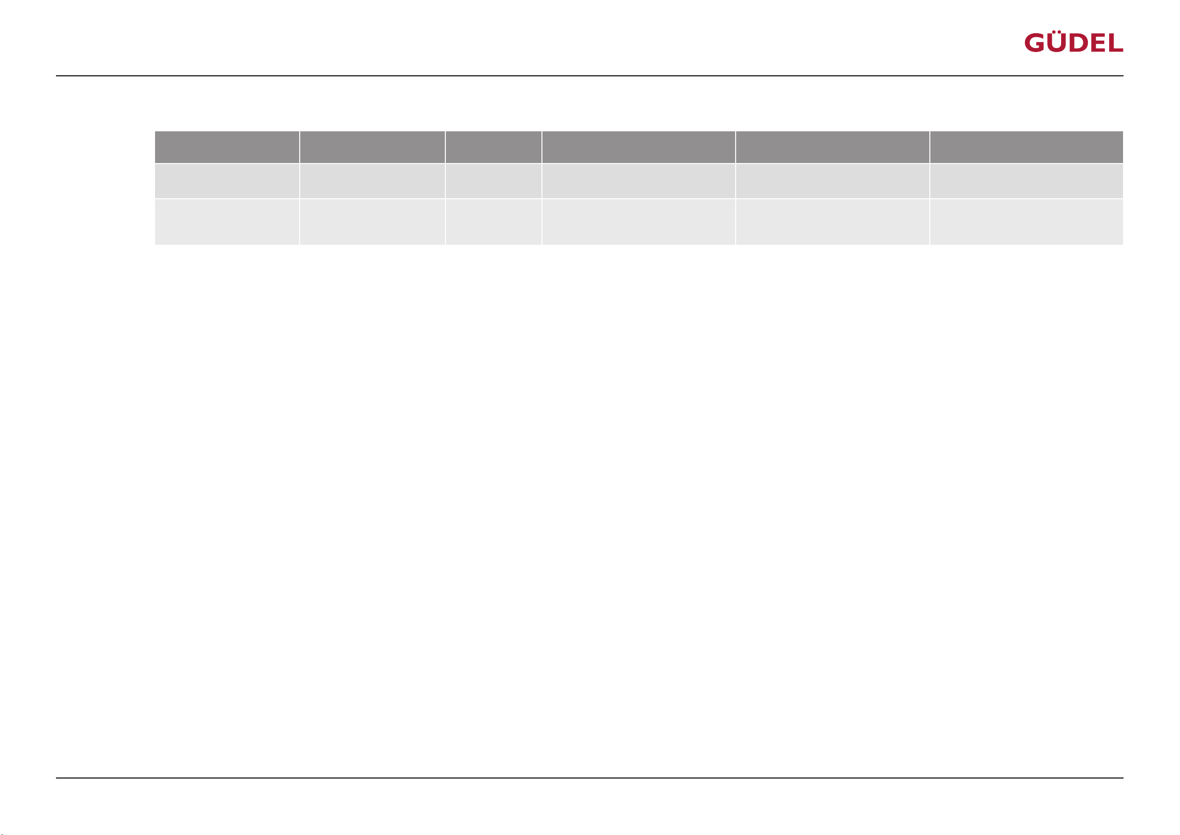
OPERATING MANUAL Automatic lubrication system
FlexxPump 404DLS
8.4 Maintenance table
Maintenance
Maintenance work Maintenance cycle [h] Duration [min] Target readership Lubricants
Replacing the cartridge 2,250 10
Checking automatic lubrication system
This table does not purport to be exhaustive.
Table8-7 Maintenance table
11,250
The manufacturer's technicians
Maintenance technicians
The manufacturer's technicians
Maintenance technicians
Further information
Cleaning agents
Güdel H1 NSF no.146621 ÜChapter8.3.2,274
mild universal cleaner free from aromatic compounds (e.g. Motorex
ÜChapter8.3.1,273
OPAL 5000)
72057594178931083_v7.0_EN-US
77
Page 78

Maintenance
OPERATING MANUAL Automatic lubrication system
FlexxPump 404DLS
78
72057594178931083_v7.0_EN-US
Page 79
OPERATING MANUAL Automatic lubrication system
FlexxPump 404DLS
9 Repairs
9.1 Introduction
Repairs
Work sequences
Original spare
parts
9.1.1 Safety
Perform the work sequences in the order described. Perform the described
tasks at the specified times. This ensures a long service life for your product.
Only use original spare parts. Ü291
Only perform the tasks described in this chapter after you have read and understood the chapter "Safety". Ü215
It concerns your personal safety!
WARNING
Automatic startup
During work on the product, there is danger of the machine starting up automatically. This can lead to severe or fatal injuries!
Before working in the danger area:
• Secure vertical axes (if equipped) against falling.
• Switch off the superordinate main power supply. Secure it against being
switched on again (main switch for the complete system)
72057594178931083_v7.0_EN-US
• Before switching on the system again, make sure that no one is in the danger area
9.1.2 Personnel qualifications
Only appropriately trained and authorized technicians are allowed to work on
the product.
79
Page 80

OPERATING MANUAL Automatic lubrication system
Repairs
9.2 Malfunctions / Troubleshooting
Malfunction Cause Measure
FlexxPump 404DLS
Lubrication system
does not lubricate
Lubrication system
does not lubricate
Lubrication system
does not lubricate
Cartridge missing/
empty or air in
FlexxPump; pump
function stopped
The measured
counter-pressure
was too high three
times in a row. Hydraulic connections
or hoses may be
Insert new cartridge or vent
FlexxPump; the pump continues running without
change
Remove cause of the
counter-pressure, switch
the FlexxPump off and on
again. The fault is set to
zero. The FlexxPump starts
up again.
blocked, hoses too
long and/or lubricant
too stiff/hard. Pump
function has been
stopped.
Various causes • Switch the FlexxPump off
and on again. This does
not delete the data memory.
• Contact the service department if the problem
reoccurs
Table9-1 Malfunctions / Troubleshooting
9.3 Service departments
If you have questions, please contact the service departments. Ü293
80
72057594178931083_v7.0_EN-US
Page 81
OPERATING MANUAL Automatic lubrication system
FlexxPump 404DLS
10 Decommissioning, storage
10.1 Introduction
Only perform the tasks described in this chapter after you have read and understood the chapter "Safety". Ü215
It concerns your personal safety!
10.1.1 Personnel qualifications
Only appropriately trained and authorized technicians are allowed to work on
the product.
Decommissioning, storage
72057594178931083_v7.0_EN-US
10.2 Storage conditions
Leaking fluids
During storage, substances that are hazardous to the environment can leak!
• Hazardous substances must be prevented from entering the drinking water
supply. Take appropriate measures
• Observe the country-specific safety data sheets
• Oils and greases must be disposed of as hazardous waste, even if the total
quantity is small
Room
Temperature
Air humidity
Store the product in a dry location. For information on the required space
and the floor capacity, refer to the layout. Use a covering to protect the
product against dust and dirt.
The ambient temperature must remain between -10 and +40 °C. Make sure
that the product is not subjected to great temperature fluctuations.
The air humidity must be below 75%.
CAUTION
81
Page 82
Decommissioning, storage
10.3 Decommissioning
10.3.1 Shutdown
Falling axes, workpieces
Falling axes or workpieces can cause physical damage, serious or fatal injuries!
• Set down any workpieces before working in the danger area
• Never enter the area below suspended axes and workpieces
• Secure suspended axes using the stipulated equipment
• Check the belts of the telescope axes for signs of breakage and tears
OPERATING MANUAL Automatic lubrication system
FlexxPump 404DLS
WARNING
Do not empty the lubrication lines and the gearbox when shutting down the
product.
To shut down the product, proceed as follows:
1 Switch off FlexxPump
2 Remove cartridge
3 Cut the power supply
The product has been shut down
10.3.2 Cleaning, rust-proofing
Clean away any dirt and dust from the product. Clean the product thoroughly. Dispose of any cloths soaked in oil or grease in an environmentally
friendly manner. Ü285
Apply corrosion protection to all bright parts.
10.3.3 Identification
Label the product with the following data:
• Date of decommissioning
• Internal machine number/name
• Additional data as per internal guidelines
72057594178931083_v7.0_EN-US
82
Page 83

OPERATING MANUAL Automatic lubrication system
FlexxPump 404DLS
10.4 Recommissioning
For recommissioning, follow the steps described for commissioning.
If the machine downtime is longer than one year, carry out the following
tasks:
• Rinse the lubrication lines with fresh lubricant
• Replace the cartridge
• Check the gaskets and replace if necessary
Decommissioning, storage
72057594178931083_v7.0_EN-US
83
Page 84

Decommissioning, storage
OPERATING MANUAL Automatic lubrication system
FlexxPump 404DLS
84
72057594178931083_v7.0_EN-US
Page 85
OPERATING MANUAL Automatic lubrication system
FlexxPump 404DLS
11 Disposal
11.1 Introduction
Observe the following during disposal:
• Adhere to the country-specific regulations
• Separate the material groups
• Dispose of the materials in an environmentally friendly way
• Recycle waste if possible
11.1.1 Safety
Only perform the tasks described in this chapter after you have read and understood the chapter "Safety". Ü215
It concerns your personal safety!
Disposal
72057594178931083_v7.0_EN-US
WARNING
Automatic startup
During work on the product, there is danger of the machine starting up automatically. This can lead to severe or fatal injuries!
Before working in the danger area:
• Secure vertical axes (if equipped) against falling.
• Switch off the superordinate main power supply. Secure it against being
switched on again (main switch for the complete system)
• Before switching on the system again, make sure that no one is in the danger area
11.1.2 Personnel qualifications
Only appropriately trained and authorized technicians are allowed to work on
the product.
85
Page 86

Disposal
11.2 Disposal
Your product consists of the following units:
• Packaging
• Consumables
• Base unit
OPERATING MANUAL Automatic lubrication system
FlexxPump 404DLS
• Contaminated materials / auxiliary agents (oil paper)
• Wood
• Plastic (film)
• Lubricants (oils/greases)
• Batteries
• Metals (steel/aluminum)
• Plastics (thermoplasts/duroplasts)
• Contaminated materials / auxiliary agents (felt / cleaning cloths)
• Electrical material (cables)
11.3 Waste management compliant assemblies
11.3.1 Disassembly
Disassemble the product as follows:
Prerequisite:Prior to disassembly, shut down the product
1 Remove connecting elements (cables / energy chains)
2 Disassemble assemblies
3 Take the assemblies apart and separate the different materials
The product has been disassembled.
72057594178931083_v7.0_EN-US
86
Page 87
OPERATING MANUAL Automatic lubrication system
FlexxPump 404DLS
11.3.2 Material groups
Dispose of the material groups in accordance with the following table:
Material Disposal method
Disposal
Contaminated materials / auxiliary
Hazardous waste
agents
Wood Municipal waste
Plastic Collecting point or municipal waste
Lubricants Collecting point disposal in accor-
dance with the safety data sheets
Ü224
Batteries Battery collection
Metals Scrap metal collection
Electrical material Electrical waste
Table11-1 Disposal: material groups
11.4 Disposal facilities, authorities
72057594178931083_v7.0_EN-US
The disposal facilities and authorities differ from country to country. Observe
the local laws and regulations concerning disposal.
87
Page 88

Disposal
OPERATING MANUAL Automatic lubrication system
FlexxPump 404DLS
88
72057594178931083_v7.0_EN-US
Page 89
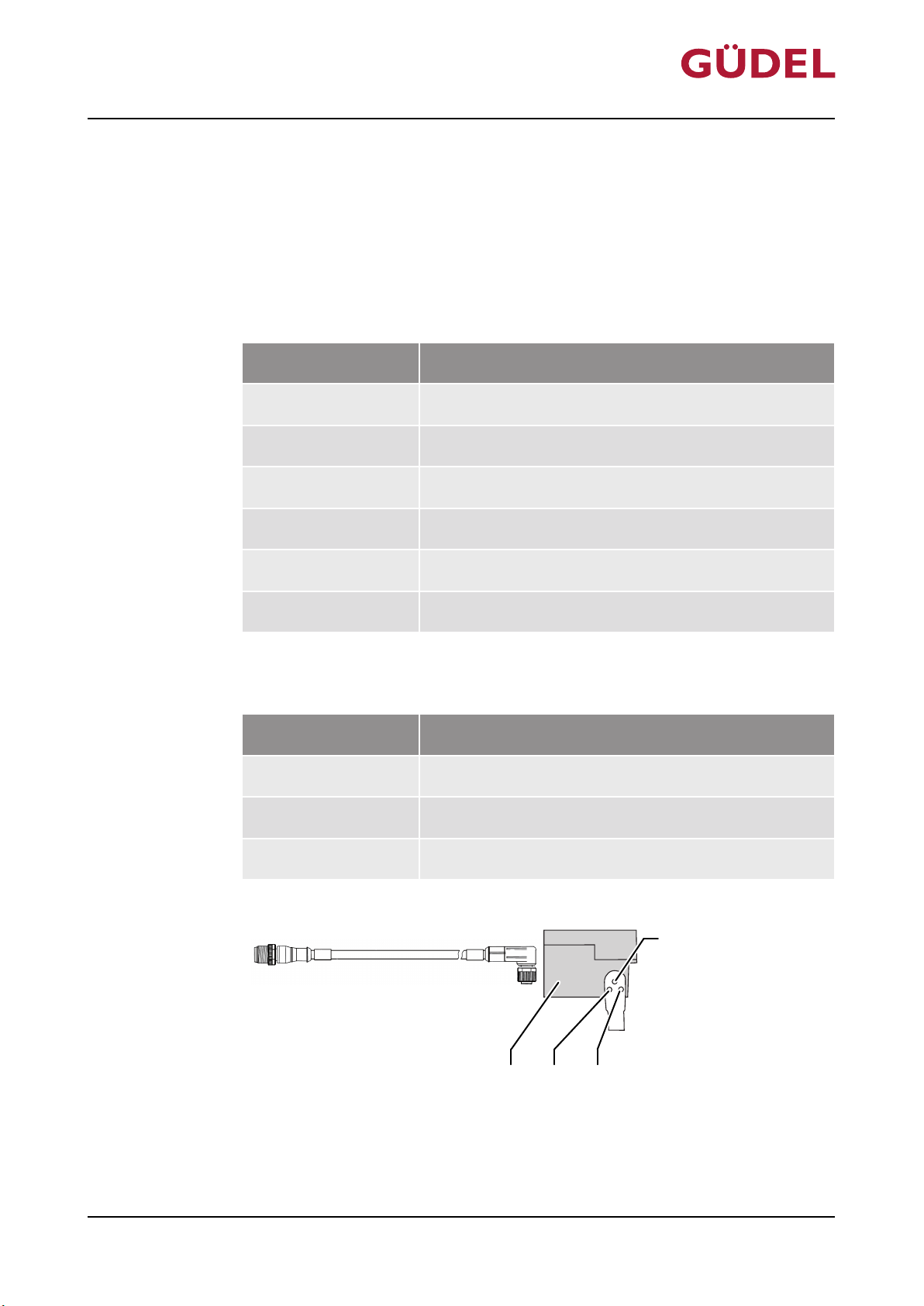
D003115
A
D C B
OPERATING MANUAL Automatic lubrication system
FlexxPump 404DLS
12 Accessories
12.1 PLC connecting cable
The following M12 connecting cables are permitted for the FlexxPump 402 /
404DLS product:
Serial number Designation
0200513 Length 1 m
0152900 Length 2 m
0200515 Length 5 m
Accessories
Round plug connection M12 4-pin pref. LED
72057594178931083_v7.0_EN-US
0200516 Length 10 m
0200517 Length 20 m
Table12-1 PLC connecting cable
The PLC connecting cables are equipped with three colored LEDs:
LED color Meaning
Green Voltage on PIN 1 is available and everything is okay
Yellow Signal on PIN 4
White Signal on PIN 2
Table12-2 PLC connecting cable: Meaning of the LED color
Fig.12-1 PLC connecting cable
A LED white C LED yellow
B LED green D FlexxPump
89
Page 90

Accessories
OPERATING MANUAL Automatic lubrication system
FlexxPump 404DLS
90
72057594178931083_v7.0_EN-US
Page 91

OPERATING MANUAL Automatic lubrication system
FlexxPump 404DLS
13 Spare parts supply
Spare parts supply
72057594178931083_v7.0_EN-US
91
Page 92

Spare parts supply
OPERATING MANUAL Automatic lubrication system
FlexxPump 404DLS
92
72057594178931083_v7.0_EN-US
Page 93
OPERATING MANUAL Automatic lubrication system
FlexxPump 404DLS
13.1 Service departments
Have the following information available for service inquiries:
• Product, type (as per type plate)
• Project number, order number (as per type plate)
• Serial number (as per type plate)
• Material number (as per type plate)
• Location of the system
• Contact person at the operating company
• Description of the issue
• Drawing number (if applicable)
Spare parts supply
Regular inquiries
If you have questions relating to service, please use the service form at www.gudel.com or contact the responsible service department:
For all other countries not included in the following list, please contact the service department in Switzerland.
Customer with special agreements should contact the service department specified in the contract.
72057594178931083_v7.0_EN-US
93
Page 94
Spare parts supply
OPERATING MANUAL Automatic lubrication system
FlexxPump 404DLS
Americas
Country Relevant service department Phone E-mail
Brazil Güdel Lineartec Comércio de Automção Ltda.
Argentina Güdel TSC S.A. de C.V.
Mexico
Canada Güdel Inc.
United States
Table13-1 Service departments Americas
+5511995908223 [email protected]
Rua Américo Brasiliense n° 2170, cj. 506
Chácara Santo Antonio
CEP 04715-005 São Paulo
Brazil
+528183742500107 [email protected]
Gustavo M. Garcia 308
Col. Buenos Aires
N.L. 64800 Monterrey
Mexico
+17342140000 [email protected]
4881 Runway Blvd.
Ann Arbor, Michigan 48108
United States
94
72057594178931083_v7.0_EN-US
Page 95
OPERATING MANUAL Automatic lubrication system
FlexxPump 404DLS
Spare parts supply
Asia
Country Relevant service department Phone E-mail
China Güdel International Trading Co. Ltd.
+862150550012 [email protected]
Block A, 8 Floor, C2 BLDG, No. 1599 New Jin Qiao Road
Pudong
201206 Shanghai
China
China press automation Güdel Jier Automation Ltd.
+8653181616465 [email protected]
A Zone 16th Floor JIER Building
21th Xinxi Road
250022 Jinan
China
India Güdel India Pvt. Ltd.
+912067910200 [email protected]
Gat No. 458/459 Mauje Kasar Amboli
Pirangut, Tal. Mulshi
412 111 Pune
India
Korea Güdel Lineartec Inc.
+82328580541 [email protected]
11-22 Songdo-dong
Yeonsu-Ku
Post no. 406-840 Incheon City
South Korea
72057594178931083_v7.0_EN-US
Taiwan Güdel Lineartec Co. Ltd.
Thailand Güdel Lineartec Co. Ltd.
Table13-2 Service departments in Asia
+88635978808 [email protected]
No. 99, An-Chai 8th St. Hsin-Chu Industrial Park
TW-Hu-Ko
30373 Hsin-Chu
Taiwan
+6623740709 [email protected]
19/28 Private Ville Hua Mak Road
Hua Mak Bang Kapi
10240 Bangkok
Thailand
95
Page 96
Spare parts supply
OPERATING MANUAL Automatic lubrication system
FlexxPump 404DLS
Europe
Country Relevant service department Phone E-mail
Denmark Güdel AG
+41629169170 [email protected]
Gaswerkstrasse 26
Finland
Industrie Nord
4900 Langenthal
Greece
Switzerland
Norway
Sweden
Switzerland
Turkey
Bosnia and Herzegovina Güdel GmbH
+437226206900 [email protected]
Schöneringer Strasse 48
Croatia
4073 Wilhering
Austria
Austria
Romania
Serbia
Slovenia
Hungary
Slovakia Güdel a.s.
Holandská 4
Czech Republic
63900 Brno
Czech Republic
Portugal Güdel Spain
C/Industria 60
Spain
Local 7
08025 Barcelona
Spain
France Güdel SAS
Tour de l'Europe 213
3 Bd de l'Europe
68100 Mulhouse
France
+420602309593 [email protected]
+34934760380 [email protected]
72057594178931083_v7.0_EN-US
+33169898016 [email protected]
96
Page 97
OPERATING MANUAL Automatic lubrication system
FlexxPump 404DLS
Country Relevant service department Phone E-mail
Spare parts supply
Germany Güdel Germany GmbH
Industriepark 107
74706 Osterburken
Germany
Germany intralogistics Güdel Intralogistics GmbH
Gewerbegebiet Salzhub 11
83737 Irschenberg
Germany
Italy Güdel S.r.l.
Via per Cernusco, 7
20060 Bussero (Mi)
Italy
Belgium Güdel Benelux
Eertmansweg 30
Luxembourg
7595 PA Weerselo
The Netherlands
The Netherlands
+4962916446792 [email protected]
+49806270750 [email protected]
+39029217021 [email protected]
+31541662250 [email protected]
72057594178931083_v7.0_EN-US
Estonia Gudel Sp. z o.o.
ul. Legionów 26/28
Latvia
43-300 Bielsko-Biała
Poland
Lithuania
Poland
Ukraine
Russia Gudel Russia
Yubileynaya 40
Belarus
Office 1902
445057 Togliatti
Russia
Ireland Güdel Lineartec (U.K.) Ltd.
Unit 5 Wickmans Drive, Banner Lane
United Kingdom
Coventry
CV4 9XA West Midlands
United Kingdom
+48338190125 [email protected]
+78482735544 [email protected]
+442476695444 [email protected]
Table13-3 Service departments in Europe
97
Page 98
Spare parts supply
OPERATING MANUAL Automatic lubrication system
FlexxPump 404DLS
All other countries
Country Relevant service department Phone E-mail
All other countries Güdel AG
Table13-4 Service departments for all other countries
Inquiries outside of business hours
If you have service inquiries outside of business hours, please contact the following service departments:
Europe Güdel AG
Americas Güdel Inc.
+41629169170 [email protected]
Gaswerkstrasse 26
Industrie Nord
4900 Langenthal
Switzerland
+41629169170 [email protected]
Gaswerkstrasse 26
Industrie Nord
4900 Langenthal
Switzerland
+17342140000 [email protected]
4881 Runway Blvd.
Ann Arbor, Michigan 48108
United States
Table13-5 Service departments outside of business hours
72057594178931083_v7.0_EN-US
98
Page 99
14.07.2008 / Page 1 of 1
VS0035 2-Amod ZP-4 M MO mec 3.10 10947-001A
EtinUytitnauQgniwarDtxeTrebmun metInoitisoP
300 V000134
Y
ktS1230-32580029=L V 52-022/022PL sixA-
EktS770.002.71.093SUGI 0.002.71.093 niahc ygrenE4001410203
400 0916667
Y
ktS2030-32584-PZ egairraC-
900 406015-10.00 Worm gear unit AE060/L left
Ratio i=10.00
AE060 2 Stk E
910 406089 Motor flange 060 18x116x116 ø130/110 8030-018a 2 Stk E
1000 0910499 Mechanical multi limit switch accessories 750 Y 8523-024 2 Stk
1100 230803 Felt pinion for lubrication
ø40.6x20, Modul m=2.387
p
itch P=7.5, Z=15
8102-039d 1 Stk V
Güdel AG
Insustrie Nord
CH-4900 Langnethal
phone +41 62 916 91 91
fax +41 62 916 95 29
[email protected]
D000094
A
OPERATING MANUAL Automatic lubrication system
FlexxPump 404DLS
13.2 Explanations regarding the spare parts list
13.2.1 Parts list
The parts list contains all parts of your product. The spare parts and wear
items are indicated as described in the explanation of symbols.
Spare parts supply
72057594178931083_v7.0_EN-US
Fig.13-1 Explanation of symbols
A Spare part status
Spare part status (column E): E = Spare part
V = Wear item
13.2.2 Position drawings
The positions of the spare parts can be seen on the drawings. These are standard drawings. Individual positions or images might differ from your product.
99
Page 100

OPERATING MANUAL Automatic lubrication system
Torque tables
14 Torque tables
14.1 Tightening torques for screws
NOTE
Vibrations
Screws without screw lock become loose.
• Secure screw connections on moving parts Loctite medium strength 242.
• Apply the adhesive on the nut thread, not on the screw!
FlexxPump 404DLS
100
72057594178931083_v7.0_EN-US
 Loading...