

Page 1
10-3 Rev. A
2018-11-7
Page 2

Owner’s Manual 65X and 85X
Document P/N 10-3
10-3 Rev. A
2018-11-7
Page 3

OWNER’S MANUAL
CO Guardian LLC FMS 65X and 85X
Aircraft data on your tablet and in the cloud
“Carbon monoxide (CO) is a
colorless, odorless, and tasteless gas
that is ... toxic to humans ... when
encountered in higher
concentrations.” - Wikipedia
10-3 Rev. A
2018-11-7
Page 4

CO Guardian LLC.
1951 E Airport Drive
Tucson, AZ 85756
Phone: 520-889-1177
8:00 am - 5:00 pm MST
http://www.guardianavionics.com
10-3 Rev. A
2018-11-7
Page 5

Table of Contents
Record of Amendments ................................................................................................... 6
Foreword ......................................................................................................................... 7
Basic Functions ............................................................................................................... 8
System Description ......................................................................................................... 9
Pin Layout FMS 65X and 85X ....................................................................................... 15
...................................................................................................................................... 17
Installation of 2 Amp CB ................................................................................................ 17
Installation of FMS 65X and 85X (See Installation Drawing 10-2) ................................. 17
Maintenance Instructions .............................................................................................. 19
Emergency Procedures ................................................................................................. 21
Warranty ........................................................................................................................ 22
Supplement 1 – Aero-Medical Aspects ......................................................................... 24
Supplement 2 - Electrical Wiring Diagram FMS 65X and 85X ............................................. 27
10-3 Rev. A
2018-11-7
Page 6

Record of Amendments
Revision No Page No. Date Description Approved by
A 1 - 26 11/7/18 Initial release Ash Vij
10-3 Rev. A
2018-11-7
Page 7

Foreword
This owner’s manual is intended to be used by persons who, pursuant to current requirements, are
qualified to install the FMS 65X and the 85X Series, cockpit carbon monoxide monitoring and
warning system. Since different aircraft have differing cockpit layouts and have differing
installment specifications, this document is not designed to be a type specific installation manual
but a generic installation guideline.
In case you require any specific information about the FMS 65X and the 85X Series, please
contact us at the address below -
Guardian Avionics
CO Guardian, LLC
1951 E. Airport Drive
Tucson, AZ 85756
(520) 889-1177
520-889-8249 (Fax)
http://www.guardianavionics.com
While every care has been taken in the preparation of this document, any errors, inconsistencies
or suggestions may be forwarded to us at the address given above. Please refer to the document
page number and name. List the details of the error and/ or inconsistency and suggested changes
to the document.
10-3 Rev. A
2018-11-7
Page 8

Basic Functions
Feature Description
Carbon Monoxide (CO)
detection
The system generates an alarm when the CO level rises above 50 parts per
million (PPM) and stays above this level for 3 min 30 seconds. The alarm
operates without any delay in case the CO level rises above 400 PPM. Data
is transmitted via an RS 232 port and a remote warning light is switched on
in case of CO crossing threshold levels.
CO warning light
Cabin altitude warning
light
Tone generator
Data transfer
Real time instrument
data accessibility via
Bluetooth
Remote reset
USB Power
This light will be switched on when the CO level is detected above the
designated threshold.
This warning light will alert the pilot at preset cabin altitudes of 10,000
feet, 12500 feet and 14,000 feet AMSL.
FMS 65X and 85X generates a tone and sends it to the aircraft audio
panel whenever an alarm condition exists.
FMS 65X and 85X unit interfaces with the RS 232 data bus and is able to
access a large number of aircraft parameters. This data can be transferred
via a Bluetooth connection (Not current available) to as many as six iOS
devices simultaneously. These devices include iPhones and iPads.
Data transferred via Bluetooth (Not current available) can be viewed in real
time over iPhones or iPads inside the aircraft.
The unit can be reset remotely either by a hard wire reset or via the RS232
data stream.
The unit has two USB ports. These can provide 2.5 Amp power each to two
smart USB devices. In case the unit is connected to a non-smart switch, it
will be able to provide 1 Ampere continuous power supply.
10-3 Rev. A
2018-11-7
Page 9

System Description
1.0 General
Carbon Monoxide (CO) can be dangerous in an enclosed space such as an aircraft cockpit. The
FMS 65X and the 85X series products are designed to be installed in the instrument panel of an
aircraft. It is designed to detect the presence of CO concentrations before they reach life threatening
levels. In addition, the FMS 65X/85X can connect to the RS232 data stream and provide real time
engine and GPS data to occupants in the aircraft who may be using iPad(s) or iPhone(s). The data
can later be uploaded to a secure cloud-based server.
10-3 Rev. A
2018-11-7
Page 10
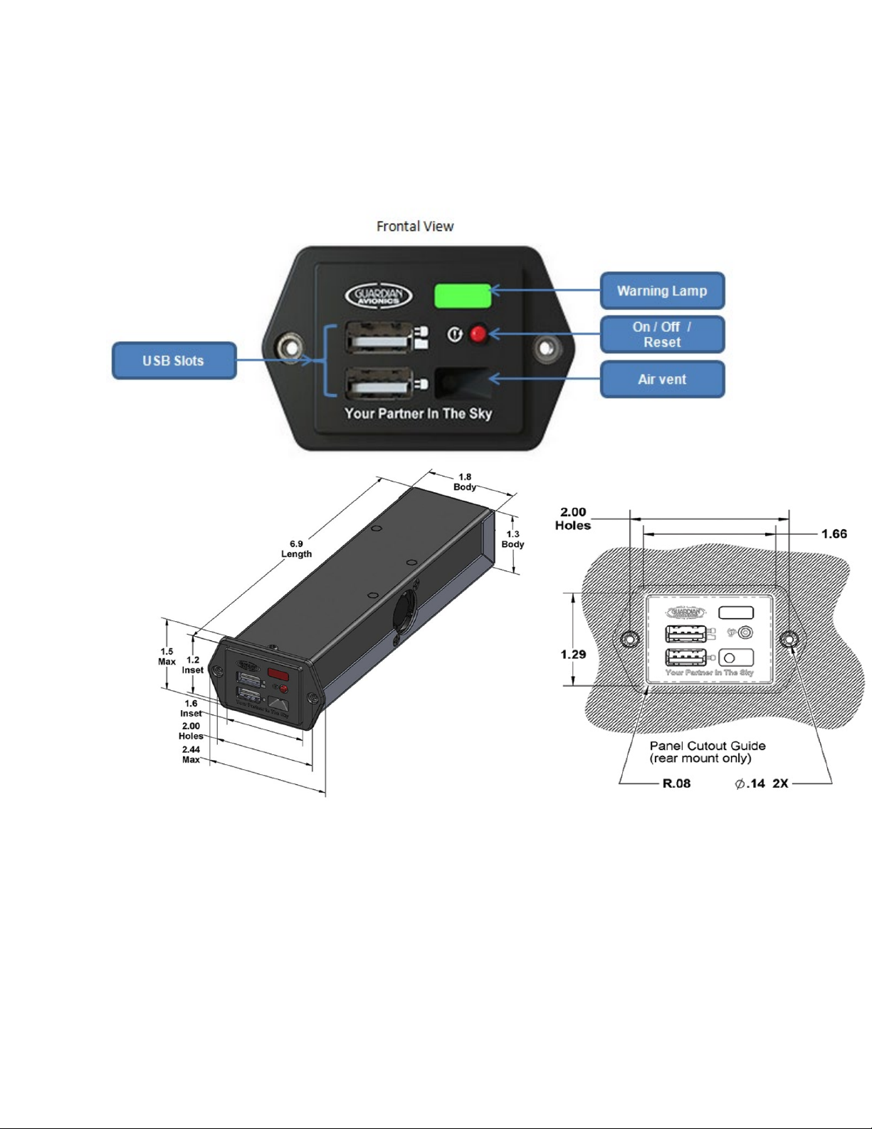
2.0 Physical Description (65X)
Dimensions (all in inches)
10-3 Rev. A
2018-11-7
Page 11

3.0 Physical Description (85X)
Page left Blank for illustration
10-3 Rev. A
2018-11-7
Page 12

4.0 Leading Particulars
Parameter Value / Specification
Dimensions
650
850
Weight 8 oz
Cooling Passive
Temperature range
Non operational temperature range
Operational temperature range
Humidity range 5% to 95% (non condensing)
Power requirements
14 V DC Model
28 V DC Model
System start up and stabilization time Three minutes
7 (length) x 1.3 (height) x 1.8 (width) (in inches)
5.75” L x 1.3” H x 4.28” W
-55° C to +85° C
-20° C to +55° C
+14 V DC (nominally 9.0 V to 15.1 V DC)
+28 V DC (nominally 18.0 V to 30.3 V DC)
Power utilization (both 14 V and 28 V models)
USB charging
Both the ports are in Auto-Detect mode and their
charging current is limited to 1 Amp. These ports
can deliver up to 2.5 Amps when under firmware
control.
On board storage
Connectivity
2 Watts without any device charging through the
USB ports
25 Watts with two devices charging through both
USB ports with firmware control
14 V @ 1.8 Amp
28 V @ 0.9 Amp
Up to 2 GB onboard storage on device is possible.
Enabled via optional purchase through the App
store.
Connectivity
10-3 Rev. A
2018-11-7
Page 13

2 x RS232 serial outputs
5 x RS232 serial inputs
Bluetooth - Range 25 feet line of sight. Can connect up to two devices.
5.0 Scope
The FMS 65X and 85X family of Carbon Monoxide detectors is designed to carry out a
number of functions that go on to make a flight safer, better managed and more
interesting. The system performs the following functions –
• Maintaining a continuous watch over the levels of carbon monoxide in the cockpit
and generating timely alerts to warn pilots of elevated CO level. The system is
capable of providing a warning on most cockpit multi-function displays (MFD).
• Monitoring the cabin altitude and alerting the pilot on reaching cabin altitudes of
10,000 feet, 12,500 feet and 14,000 feet
• Access all data that is available on the RS232 bus and display it on a special
FMS65X and 85X App that runs on the iPhone/ iPad
• Use the iPhone/ iPad to transfer aircraft performance data to cloud-based storage
(once the device has network connectivity)
• Store aircraft performance data on its internal 2 GB storage
• Provides a USB charger for up to two devices in flight
6.0 Carbon Monoxide level monitoring and warning
10-3 Rev. A
2018-11-7
Page 14
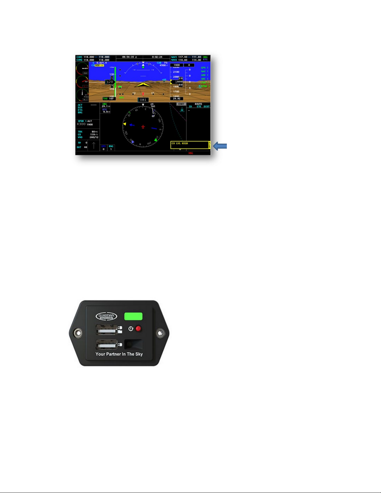
higher concentrations of carbon monoxide. At 400 PPM, the alert is nearly
instantaneous.
• The alert is displayed on the pilot’s instrument panel MFD. An audio warning is also
generated that is supplied to the pilot’s headset.
The alert will stay ‘ON’ on the pilot’s instrument panel MFD until the level of CO
concentration drops below 50 PPM.
In addition to the warning being displayed on the MFD, the large, green lamp on the face
of the FMS 650 will turn yellow within three and half minutes if the CO level is detected
to be in the region of 50 to 100 PPM. If the level crosses 101 PPM, the lamp will turn red
without any delay.
7.0 Cabin Altitude monitoring and warning
FMS65X and 85X has an in-built pressure sensor that monitors the cabin altitude of the
cockpit. As the cabin altitude increases, the system becomes more sensitive to the
presence of CO in the cockpit. Besides this, the system warns the pilot if the cabin
altitude exceeds preset values. The indications are as given below –
The system monitors the carbon
monoxide content in the air in the
cockpit and generates an alert
under the following conditions –
• If the carbon monoxide
concentration reaches 50 parts per
million (PPM) or more, an alert is
generated within 3.5 minutes
• The alert delay is reduced at
10-3 Rev. A
2018-11-7
Page 15

FMS Pinout
Comments
Pin
1
Power
14 or 28 VDC
2
Reset
Power Up Reset Button
3
Spare Ground
Standard airplane ground
4
CO Light (Relay 1)
CO Alert
5
Ground
System Ground
• On cabin altitude exceeding 10,000 feet, the warning lamp on the 65X comes on
for a short period to alert the pilot. On the 85X series will be on if the CO Alarm
output is connected.
• On cabin altitude exceeding 12,500 feet, the warning lamp comes on continuously
after a time delay of 30 minutes.
• On cabin altitude exceeding 14,000 feet, the warning lamp comes on immediately.
These warnings will come on even if the carbon monoxide level in the cockpit is
absolutely normal.
8.0 Service Facilities (all models)
The operator can service all other components of the installation at an FAA certified Repair Station
or by an A&P mechanic. CO Detectors must me be returned to CO Guardian for repair, calibration
or overhaul. The sensor life is approximate 7 years.
Note -
The sensor requires special gases for testing. If any discrepancies are found with the unit
during installation or during the operational service life, the unit must be returned to CO
Guardian for repair or replacement. The CO Detector unit must be returned to the
manufacturer for CO sensor replacement and re-calibration at the end of the service life as
applicable to the specific unit in use.
Pin Layout FMS 65X and 85X
The pin layout of the FMS 65X and 85X is as under -
10-3 Rev. A
2018-11-7
Fifteen
Page 16

6
Audio Tone
500 Ohms Output
7
RS232-Out1
See Installation Drawings
8
RS232-IN1
See installation Drawings
9
Relay 2
Cabin Altitude Light
10
RS232-IN2
JPI Engine Monitor
11
RS232-IN3
Not Used
format
13
RS232-IN5
SL30/40
14
RS232-Out2
SL30/40
15
Not Used
16
Not Used
17
Not Used
18
Not Used
19
Not Used
20
Not Used
21
Not Used
22
Not Used
23
Not Used
24
Not Used
25
Not Used
26
Not Used
12 RS232-IN4 GPS In-(Aviation Data 1 and 2)
10-3 Rev. A
2018-11-7
Page 17
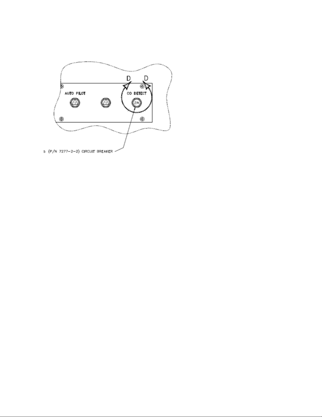
Installation of 2 Amp CB
A 2 Amp circuit breaker will need to be
installed for the FMS 65X and 85X. A
typical install is shown in the figure.
The CB should ideally be mounted on
the Essential Bus that will not be
automatically isolated in the event of a
generator failure.
The CB must be properly annotated or
labeled as shown in the figure. Ensure
that the power and ground return wires
are twisted together at 6 or more turns
per foot.
Connect Pin 1 of the FMS 65X and 85X unit to +14 V DC or +28 V DC as applicable to the aircraft
and the type of FMS 65X and 85X voltage rating through the 2 Amp CB installed for the unit.
Connect the ground return wire (Pin 5) to a suitable aircraft structure near the CB panel. The CB
will provide power supply to three components – Pin 1 of FMS 65X and 85X, the CO warning
light and the optional cabin altitude warning light. The circuit diagram is shown in detail in
Supplement 2 to this manual (page 27).
Installation of FMS 65X and 85X (See Guardian Avionics Installation Drawing 10-2)
9.0 Basic Requirements
The following basic requirements have to be insured while installing FMS65X and 85X
• Choose a location on the instrument panel that can be accessed by both pilot and
co-pilot
• Ensure that the airflow to the unit is not restricted
• Ensure that the location selected for installation is not subjected to dust or dirt
• Ensure that the air intake on the front of the unit is not obstructed or blocked in
any manner
10-3 Rev. A
2018-11-7
Page 18

• Ensure that the unit is not exposed to a strong airflow. The sensor performs better
if it is not subjected to strong airflow
• Ensure that the unit is used within the temperatures and humidity restrictions as
mentioned in the leading particulars (page 12).
10.0 Mounting FMS 65X and 85X
FMS 65X is mounted to the instrument panel and the FMS85X are mounted behind the
instrument panel as shown In Drawing 10-2.
11.0 Post Installation Checks
(a) With the CO Detector disconnected from the aircraft harness, conduct a
continuity check of the added aircraft wiring.
(b) Turn ON the aircraft Battery Switch. Close the CO DETECT circuit
breaker and measure aircraft voltage between pins 1 and 5 of the CO Detector
connector.
(c) Put aircraft Battery Switch OFF. Connect the CO Detector connector to
the aircraft harness. Turn aircraft Battery Switch ON. Close CO DETECT circuit
breaker.
(d) Verify the unit can be shut off with the CO DETECT circuit breaker.
(e) Determine the moment arm for the installed CO Detector location and
record in aircraft weight and balance manual. CO Detector weight is 8 oz
approximately.
(f) Download guardian Avionics imfd App from apple app store in search
field “Guardian Avionics”.
(g) See Guardian Avionics Smart MFD App (10-1) user guide to learn basic
features on using the app and programing the hardware to your specific needs.
(h) See www.youtube.com and search “Guardian Avionics channel” for help
videos.
12.0 RS232 DATA BUS
The RS232 Data Bus option is currently available on numerous MFD units. The RS232
data buss output will couple FMS 65X and 85X status information to electronic display
systems with RS232 input capability. If this is done, any warnings generated by FMS
65X and 85X will be displayed on the MFD (see the diagram on page 13).
More detailed information on managing the RS232 interface and connecting other
devices such as the FMS65X and 85X will be available in the installation manual of the
MFD. In some cases, 65X and 85X can be be reset through the RS232 interface (if the
MFD system in use supports this feature).
10-3 Rev. A
2018-11-7
Page 19

13.0 Bluetooth Connectivity
FMS 65X and 85X incorporates a Bluetooth chip that can integrate with any electronic
device that supports Bluetooth. Once paired with such a device such as an iPhone or the
iPad, the unit will connect automatically everytime the unit is powerd up.
If the paired device has the optional Pilot FMS App loaded then data from the RS232
data buss can be displayed on the iPhone/ iPad and be transferred to the cloud for secure
storage. Real time engine data, flight information, CO levels, GPS data and the pilot and
airframe logbook can all be managed from the App.
If the unit is not being detected by the Bluetooth of your
iPhone/iPad, go to Bluetooth setting on iPhone/iPad, select
'forget this device' and try to reconnect again.
Maintenance Instructions
The CO Detector unit has its own internal built in test mechanism and every time it is
powered up, it conducts a self diagnostic test. In case the device fails the test, this is
indicated by the warning lamp blinking red after the equipment is switched ON. If the
equipment clears the built in test the warning lamp will stay green.
Field repairs are permissible on all components of the CO Detector except on the
CO Detecting element and its indicator. In case these components are found faulty,
the unit must be returned to CO Guardian, LLC for service / repair.
The aircraft wiring harness, circuit breaker, alert annunciation, and Test/Reset switch
shall be included in the aircraft maintenance instructions for general visual inspections
for system integrity, installation security, corrosion and chaffing.
14.0 Scheduled Maintenance
The following scheduled maintenance program tasks are to be added to the aircraft
operator’s airplane maintenance program -
10-3 Rev. A
2018-11-7
Page 20

Maintenance Task
Periodicity
Recommended Periodic Scheduled Servicing Tasks:
Recommended Periodic Scheduled Preventative
Maintenance test/checks to determine system condition
ft).
and/or latent failures:
Note:
Be sure the vent on the faceplate is free of obstructions.
Recommended Periodic Inspections: None required
None required
Each time the unit is
turned ON
Recommended Periodic Structural Inspections
Required CO Sensor replacement and calibration.
None required
At the end of service life
(7 years from date of first
flight greater than 1000
The Unit must be returned to Guardian Avionics at the end of Service Life for replacement
and calibration of the CO sensor to maintain airworthiness of the unit. The main reason for
replacement of the sensor is the degradation of the sensor and dirt accumulation over the
years. Field service or overhaul of models is NOT authorized.
15.0 Weight and Balance
10-3 Rev. A
2018-11-7
Page 21

FMS 65X and 85X weighs 8 oz / 0.5 lbs. The moment arm for the equipment will need to
be calculated from the aircraft weight and balance manual.
16.0 Limitations
FMS 65X and 85X is not designed to replace any existing instrument or indicator
required by the type design or operating limits.
17.0 Self Test
When power is applied to the FMS 65X and 85X CO Detector, a self-test routine begins.
The test checks for functionality of the critical components such as the CO sensor,
temperature and pressure sensors, and the integrity of the total CO Detector system,
including the Bluetooth system (No currently available). When all systems clear the self
test, the warning lamp on the FMS65X and 85X instrument turns and stays green. In case
any component fails the test, the warning lamp will turn red and blink.
Emergency Procedures
If the CO Detector ALERT annunciation activates in flight:
• Shut off the heater, air conditioning or any other opening to the engine
compartment.
• Open a fresh air source immediately.
• Don't smoke.
• Use 100% oxygen, if possible.
• Land as soon as conditions permit.
• Be sure the source of the contamination is corrected before further flight.
Note: the alert message on the MFD will stay ON till the CO level stays above 50
parts per million (PPM) by volume of carbon monoxide concentration.
DO NOT recycle the unit via the circuit breaker since FMS 65X and 85X will need
at least two minutes for the CO sensor to stabilize after each power up.
18.0 Unit Failure
10-3 Rev. A
2018-11-7
Page 22

A failure of the CO Sensor, Temperature Sensor, or the Micro-controller will result in the
warning lamp coming on.
In case of failure indications, attempt to clear the failure by resetting FMS 65X and 85X
via the CB. If the failure indication persists or recurs, remove the power supply to the unit
by pulling the circuit breaker from the system.
Warranty
WARRANTY COVERAGE: CO GUARDIAN LLC. WARRANTS TO THE ORIGINAL CONSUMER
PURCHASER, THAT THE FMS 65X and 85X CO DETECTOR WILL BE FREE OF DEFECTS IN
MATERIAL AND WORKMANSHIP FOR A PERIOD OF ONE (1) YEAR FROM DATE OF
PURCHASE. THE MANUFACTURER'S LIABILITY HEREUNDER IS LIMITED TO
REPLACEMENT OF THE PRODUCT, REPAIR OF THE PRODUCT OR REPLACEMENT OF
THE PRODUCT WITH A REPAIRED PRODUCT AT THE DISCRETION OF THE
MANUFACTURER. THIS WARRANTY IS VOID IF THE PRODUCT HAS BEEN DAMAGED BY
ACCIDENT, UNREASONABLE USE, NEGLECT, TAMPERING OR OTHER CAUSES NOT ARISING
FROM DEFECTS IN MATERIAL OR WORKMANSHIP. THIS WARRANTY EXTENDS TO THE
ORIGINAL CONSUMER PURCHASER OF THE PRODUCT ONLY.
Warranty Disclaimers: Any implied warranties arising out of this sale, including but not limited to
the implied warranties of description, merchantability and fitness for a particular purpose, are
limited in duration to the above warranty period. In no event shall the Manufacturer be liable for
loss of use of this product or for any indirect, special, incidental or consequential damages, or
costs, or expenses incurred by the consumer or any other user of this product, whether due to a
breach of contract, negligence, strict liability in tort or otherwise. The manufacturer shall have no
liability for any personal injury, property damage or any special, incidental, contingent or
consequential damage of any kind resulting from gas leakage, fire or explosion.
Some states do not allow limitations on how long an implied warranty lasts, so the above limitation
may not apply to you.
Some states do not allow the exclusion or limitation of consequential or incidental damages, so the
above limitations or exclusions may not apply to you.
Legal Remedies: This warranty gives you specific legal rights and you may also have other rights
that vary from state to state.
Warranty Performance: During the above warranty period, your product will be replaced with a
comparable product if the defective product is returned, postage prepaid, to CO Guardian,
Customer Service Department, 1951 East Airport Drive, Tucson, AZ 85756, together with proof
of purchase date. Please include a note describing the problem when you return the unit. The
10-3 Rev. A
2018-11-7
Page 23

replacement product will be in warranty for the remainder of the original warranty period or for
six months whichever is longer. Other than the cost of postage, no charge will be made for
replacement of the defective product.
Important: Do not attempt to open unit. If unit is opened, warranty will be void.
Your Carbon Monoxide Alarm is not a substitute for property, disability, life or other insurance
of any kind. Appropriate insurance coverage is your responsibility. Consult your insurance
agent.
NOTE
The warranty will be void if the unit is opened or tampered with.
10-3 Rev. A
2018-11-7
Page 24

% COHb
Effect
Supplement 1 – Aero-Medical Aspects
19.0 Effects of Carbon Monoxide on the human body
Even small concentrations of CO in Hemoglobin (Hb) (the active component of red blood cells
in the human blood) can have an impact on human health. The table below shows the impact of
increasing concentrations of COHb.
10
15 Mild headache.
Symptoms vary widely based on exposure level, duration and the general health and age of an
individual. The symptoms most significant in the recognition of carbon monoxide poisoning
include: headache, dizziness and nausea. These 'flu like' symptoms are often mistaken for a real
case of the flu and can result in delayed or misdiagnosed treatment. If you experience these
symptoms and your CO detector alarm is sounding, a potentially serious buildup of carbon
monoxide exists.
25
30
45 Unconsciousness
50+ Death
No symptoms. Heavy smokers can have as much as 9%
COHb.
Nausea and serious headache. Fairly quick recovery after
treatment with oxygen and/or fresh air.
Symptoms intensify. Potential for long term effects
especially in the case of infants, children, the elderly, victims
of heart disease and pregnant women.
20.0 Effect of Cabin Altitude on Individuals
“Hypoxia (also known as Hypoxiation or Anoxemia) is a condition in which the body or a region
of the body is deprived of adequate oxygen supply”, Wikipedia.
10-3 Rev. A
2018-11-7
Page 25

The effects of hypoxia1 on a given person cannot be accurately predicted. For example, a person
may be relatively unaffected one day, but highly susceptible the next. It is difficult to detect
hypoxia, because its victims are seldom able to judge how seriously they are affected, or if they
are affected at all. The unpleasant sensations experienced in suffocation are absent in the case of
hypoxia. Blurring of vision, slight shortness of breath, a vague, weak feeling, and a little dizziness
are the only warnings. Even these may be absent or so slight as to go unnoticed. While still
conscious, the aviator may lose all sense of time and spend his/her last moments of consciousness
in some apparently meaningless activity. In such a condition, a person is a menace to the crew as
well as to himself. Since the aviator understands that it is the reduced air pressure at higher altitudes
that determines the effect on the body, dependence should be upon the altimeter rather than
sensations or judgment to determine when oxygen is needed. The effects of hypoxia at various
altitudes are discussed in the following paragraphs.
Below 10,000 Feet - At or below 10,000 feet, some effects of hypoxia may be present.
Generally, the eye is the first part of the body to suffer effects of hypoxia. Even at a relatively low
altitude of approximately 5,000 feet, where no other effect of hypoxia can be detected, night
vision is appreciably reduced. At 10,000 feet, night operations may be seriously handicapped by
poor night vision, which is due to mild oxygen starvation. Thus, the use of supplemental oxygen
on night flights above 5,000 feet is required. Although hypoxia affects the eyes in the daytime
as well as at night, the results during the day are usually not as noticeable below 10,000 feet.
Between 10,000 and 15,000 Feet- Although efficiency may be considerably impaired at 10,000
to 15,000 feet, death from oxygen starvation at these altitudes is virtually unknown. The greatest
dangers are from errors in judgment or performance due to drowsiness or mental confusion. At
these altitudes, long flights without oxygen produce persistent drowsiness and excessive fatigue
for many hours afterward. Frequently, persistent headaches develop soon after completion of the
flight. For these reasons, the use of oxygen on flights above 10,000 feet is required. Portable
oxygen systems are available for aircraft that do not have oxygen equipment.
Between 15,000 and 20,000 Feet - Flights at 15,000 to 20,000 feet, even for short periods, must
not be attempted without the use of oxygen. Collapse and unconsciousness are common. Failure
to use oxygen could result in death, especially when the situation is complicated by loss of blood
in combat or by shock due to pain or fear.
Between 20,000 and 25,000 Feet - During World War II, most military flying was done in
unpressurized aircraft at altitudes of between 20,000 and 25,000 feet. Most of the resulting anoxia
deaths occurred in this altitude range. The general symptoms of drowsiness, mental confusion, dim
vision, and dizziness occur here, as at lower altitudes, but they come on much more quickly,
allowing less opportunity for corrective action. Consequently, under no circumstances should
1
http://www.tpub.com/content/aviation/14020/css/14020_141.htm
10-3 Rev. A
2018-11-7
Page 26

aircraft ascend to these altitudes, even for short periods, without the use of oxygen by all persons
aboard. The movement of personnel in the aircraft requires the constant use of walkaround
equipment.
21.0 Time of Useful Consciousness
“Time of useful consciousness (TUC) is defined as the amount of time an individual
is able to perform flying duties efficiently in an environment of inadequate oxygen
supply. It is the period of time from the interruption of the oxygen supply or exposure
to an oxygen-poor environment to the time when useful function is lost, and the
individual is no longer capable of taking proper corrective and protective action. It
is not the time to total unconsciousness. The TUC has also been called Effective
Performance Time (EPT).” – Wikipedia.
10-3 Rev. A
2018-11-7
Page 27

The table below reflects various altitudes with the corresponding average TUC
Supplement 2 - Electrical Wiring Diagram FMS 65X and 85X
See Wiring Diagram 10-2 Rev. Orig or Later
For installation see latest installation drawing 10-2 @ www.guardianavionics.com under
downloads
Flight Level Time of Useful Consciousness
FL 150 30 min or more
FL 180 20 to 30 min
FL 220 5-10 min
FL 250 3 to 6 min
FL 280 2.5 to 3 min
FL 300 1 to 3 min
10-3 Rev. A
2018-11-7
Page 28
Forever sniffing for hidden dangers to keep aviators safe…
Rev X1
 Loading...