

Page 1
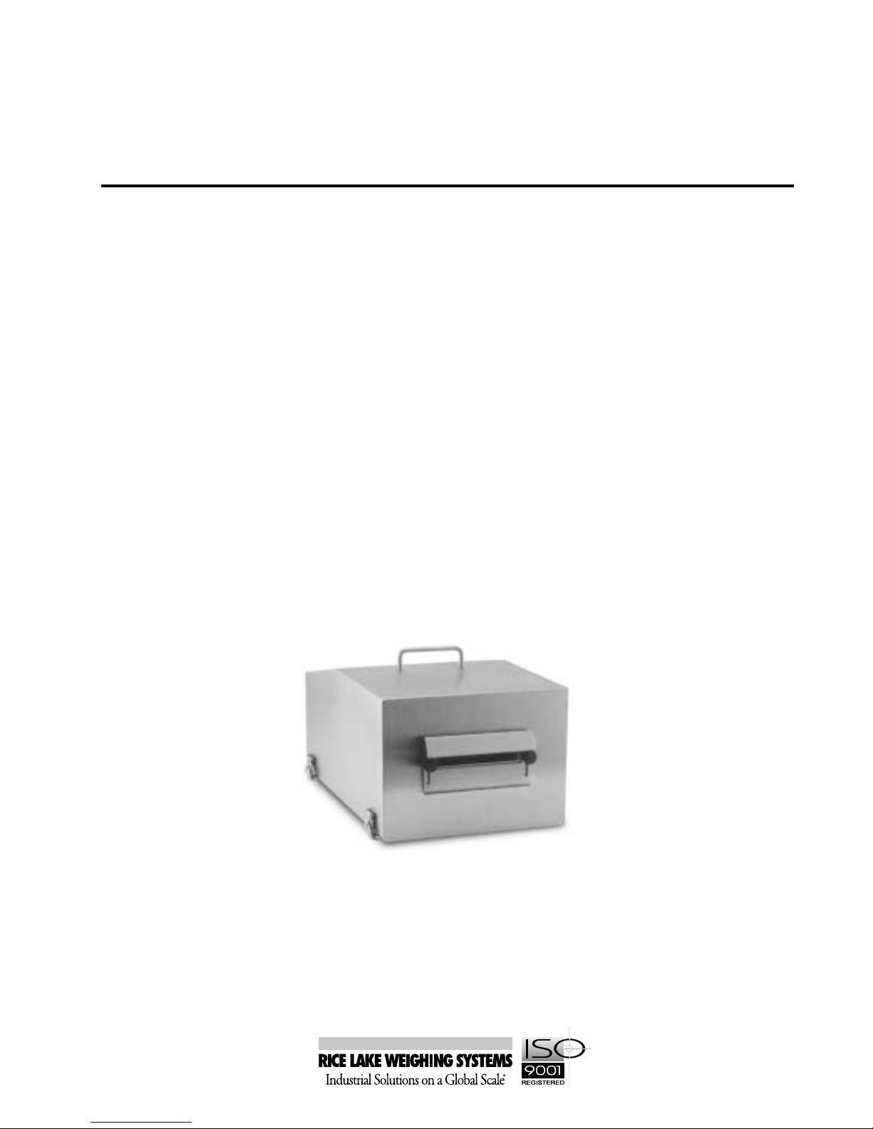
GUARDIAN G-2 CS
Stainless Steel Printer Enclosure
Enclosure Instructions
46709
Page 2

Contents
1.0 Installation................................................................................................................................ 1
1.1 Open Guardian G-2 CS Cover ................................................................................... 1
1.2 Install the Power Unit Supply...................................................................................... 1
1.3 Remove the Cable Sealing Plate................................................................................ 1
1.4 Set the Printer into Enclosure..................................................................................... 1
1.5 Close Cover................................................................................................................ 2
2.0 Enclosure Options..................................................................................................................... 2
2.1 Attaching the Terminal Block...................................................................................... 2
2.2 Installing the Heating Unit........................................................................................... 2
2.2.1 Options Power Supply Connection ................................................................................................. 2
2.2.2 Heater Cord Connection ................................................................................................................. 2
2.3 Installing the Axial Ventilating Fan.............................................................................. 3
2.4 Label Peel Option (factory installed)........................................................................... 3
3.0 Cleaning and Maintenance ...................................................................................................... 3
4.0 Warranty ................................................................................................................................... 3
Copyright © 2000 Rice Lake Weighing Systems. All rights reserved. Printed in the United States of America.
Specifications subject to change without notice.
November 2000
Page 3

1.0 Installation
The Guardian® G-2 CS features an 18-gauge stainless
steel enclosure that provides enhanced protection against
washdown environments and high humidity. Standard
features also include a bottom plate, mounting plate for
the printer, power supply, and cables. Use the diagram
on page 4 to help guide you through the installation
instructions.
1.1 Open Guardian G-2 CS Cover
To open the Guardian G-2 CS cover, release the four
butterfly latches located at the bottom four corners of
the enclosure. Push down on the enclosure to fully
open the latches. Then lift the cover away from the
base.
1.3 Remove the Cable Sealing Plate
Remove the four bolts that hold the cable sealing plate
in place. Pull the cable sealing plate away from the
base. Route the printer data transmission cord, power
supply cord, and options power cord through the base
opening and the four cable mounts. Loop cable ties
through the mounts to secure the cords in place.
Notes:
• The options power cord is only provided if you are
installing an option.
• Excess Eltron printer power cord is coiled and
stored under mount plate. Excess Datamax
power cord is tightly wound and attached to extra
adhesive cable mount.
1.2 Install the Power Unit Supply
Loosen the three nuts on the power supply bracket and
slide the power supply unit underneath the brackets as
shown below. Tighten the three nuts to secure the
power supply.
1.4 Set the Printer into Enclosure
Place the printer onto the mounting base of the
enclosure. If you are installing the Datamax printer, its
footpads fit into the recessed holes in the base of the
enclosure. Attach the necessary cables and power cord
to the printer.
Place the cable sealing plate back in its original location.
The cords should be between the base gasket and the
cable sealing plate. Reinstall the screws in the cable
sealing plate and tighten snugly so the base gasket
compresses around the cables.
1
Page 4

1.5 Close Cover
Close and latch the cover. Tighten the butterfly
lockdown latches. Open the label access door to begin
printing labels. Note: Be sure to close the label access
door before cleaning the enclosure.
2.0 Enclosure Options
Optional features of the Guardian G-2 CS Printer
enclosure include:
• Heating unit
• Axial ventilating fan
2.1 Attaching the Terminal Block
Before installing the axial venting fan or heating unit,
you must attach the terminal block to the side of the
power supply bracket. To do this, align the insulator
plate and block with the appropriate holes and tighten
into place with two standoffs and screws. Adhere a
cable mount on each side of the terminal block. (See
diagram on page 4.)
2.2 Installing the Heating Unit
Place the heater bracket with attached heating unit over
the base and tighten the two studs into place. Route the
cable through the two cable mounts located on the
power supply bracket and base, to the terminal block.
2.2.1 Options Power Supply Connection
Connect the green and yellow ground wire from the
power cord and the six-inch green and yellow ground
wire jumper to the ground stud located next to the
printer power switch. Be sure the wires are securely
positioned between the two stud nuts. Attach the other
end of the six-inch green and yellow ground jumper
wire to the upper right connection of the terminal
block. Route the blue and brown wires from the options
power cord through the cable mount to the lower right
and middle right connections on the terminal block as
shown in the diagram below. Apply adhesive ground
sticker next to ground stud on base.
2.2.2 Heater Cord Connection
Attach the heater cord to the terminal block as shown
in the diagram below.
Heater Cord
Green
Black
White
Power Cord
Green and Yellow
Brown
Blue
If you are installing only the heater option, slide the
protective warning shield over the terminal block
standoffs and secure with two nuts.
2
Options
Page 5

2.3 Installing the Axial Ventilating Fan
Attach the fan to the top of the power unit bracket and
tighten with four screws and four nylock nuts. Then run
the fan wires to the terminal block. Attach the fan cord
to the terminal block as shown in the diagram below.
Brown
Note: If you haven’t already installed the heater unit,
see Section 2.2.1 on page 2.
Green and Yellow
Brown
Blue
3.0 Cleaning and Maintenance
To extend the shelf life of the Guardian G-2 printer
enclosure, do the following:
1. Unplug the power cord.
2. Close main cover and secure it tightly with the
four butterfly latches on each side of cover.
3. With a damp (not wet) sponge or cloth, clean
around immediate area of label slot. Then
fasten label access cover securely in place with the
plastic knobs provided. The label access cover
must be fastened in place before proceeding.
4. Use a sponge or scrubbing brush and soapy water
to wash down the printer cover.
5. Rinse printer by splashing with cold water.
4.0 Warranty
The Guardian G-2 CS is covered by Rice Lake Weighing
Systems standard product limited warranty. Please
refer to the Electronic Replacement Parts &
Components catalog for further information.
2.4 Label Peel Option (factory installed)
The Label Peel Option (RLWS PN 53965) is composed
of a new enclosure with an opening for the label with
internal rewind. A solid splashguard with gasket is
supplied to cover opening during clean up.
3
Page 6

Axial Ventilating Fan
Terminal Block
Protective Warning
Shield
Heating Unit
DISCONNECT POWER BEFORE SERVICING
HIGH VOLTAGE
Power Supply Bracket
WARNING!
Power Supply Unit
Ground Stud
Nuts
Cable Mounts
Cable Sealing
Plate
Base
4
 Loading...