

Page 1
K3590-GP 3/03
INSTALLATION GUIDE
GENERAL INFORMATION
The FA6150KP-GP is an addressable, fixed-word display,
remote keypad designed for use with GUARDIAN
PROTECTION control panels. The address is set via the
keypad keys, and may be continuously backlit for
convenience (depending on the control panel being used).
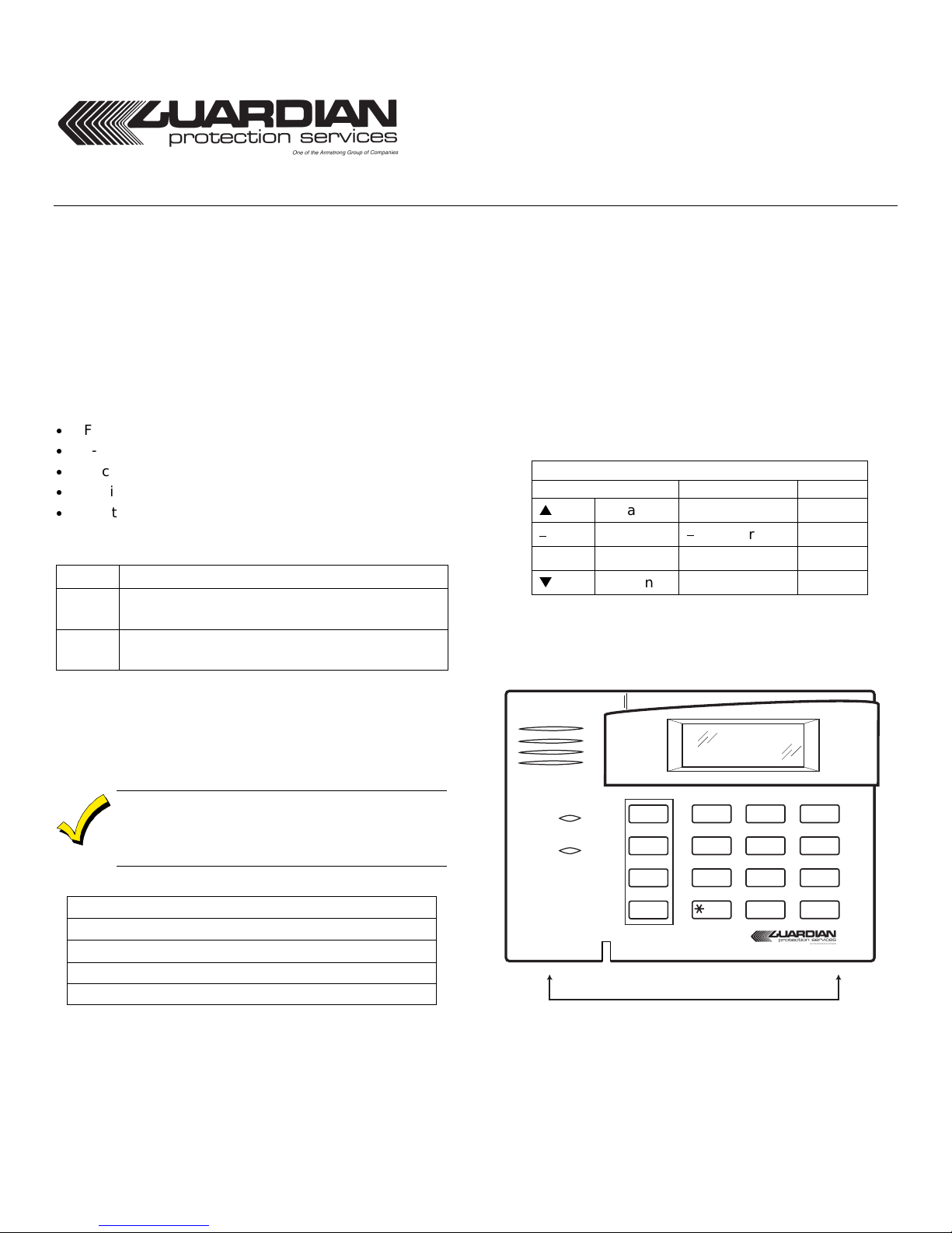
KEYPAD DISPLAY AND LEDS
The keypad has the following display features:
x
Fixed-Word display of System Status
x
3-digit Zone Identifier
x
Backlit Display (optional on some controls)
x
Dedicated Special Function Keys
x
Built-in Piezo Sounder
The following table shows the LEDs and their functions:
LED Function
Red
Green
The keypad’s Special Function Keys; A, B, C, and D, may be
programmed for panic alarms or other special functions
such as single-button arming or macros. See the control
panel’s Installation and Setup Guide for details.
Lights when the system is “ARMED” in any
mode
Lights when the system is "READY" to be
armed.
Function keys must be held down for at least 2
seconds to activate an alarm; key pairs activate
immediately.
Special Function Keys/Panic Alarm Key Pairs
or [1] & [✱]
A
or [✱] & [#]
B
or [3] & [#]
C
(Special Functions only)
D
Refer to the control panel's Installation and
Setup Guide for Special Function Key options.
FA6150KP-GP
REMOTE KEYPAD
WIRING AND INSTALLATION
The keypad can be surface mounte d directly to a wall, or to
a single- or double-gang electrical box.
1.
Remove the case back
along the keypad's bottom edge and pulling the two
halves apart. See Figure 1 below.
2.
Route wiring from the control panel
opening in the case back.
3.
Mount the case back
4.
Wire directly from the keypad’s terminal block
the terminal block on the control board as follows:
Keypad Control Panel Color
V
G Data Out
GND
+ +12VDC + Aux Pwr
W
Y Data In
See the control panel’s Installation Instructions for
more complete details.
5.
Reattach the keypad
ARMED
READY
MOUNTING RELEASE SNAPS
Figure 1. FA6150KP with Protective Door Removed
by pushing down two "snaps"
to a wall or electrical box.
Wiring Table
Data In
OFF
MAX
AWAY
TEST
CODE
3
6
9
#
2
5
8
0
Aux Pwr
Data Out
to its case back.
1
4
INSTANT
7
READY
through the
Green
Black
Red
Yellow
STAY
BYPASS
CHIME
to
6150-005-V0
Page 2

SETTING THE KEYPAD ADDRESS
The keypad can either be set for an address of 00-30, or to
the non-addressable mode (31). The keypad's default
address is 31. (See the control panel’s instructions for
specific addresses for the control you are using.)
To change the keypad's address, do the following:
1. Enter address mode: Power up the keypad. Within 60
seconds of power-up, press and hold down the [1] and [3]
keys at the same time for 3 s econds. (If unable to enter
address mode, power up and try again.)
The current keypad address will be displayed, and the
cursor will be under the "tens" digit. If 10 seconds have
passed with no key entry, the ke ypad a utom atica lly e xits
address mode. You must power down, power up and
start address mode again.
NOTE:
panel to which it is connected is in programming mode.
2. Set the current address to "00": Press [0] to clear the
current "tens" digit. The cursor will move to the "ones"
digit position. Press [0] to clear the current "ones" di git.
The cursor will move back to the "tens" digit position.
3. Enter the keypad's address: Enter the proper "tens" digit
of the keypad's address. The cursor will move to the
"ones" digit position. Enter the proper "ones" digit o f the
keypad's address. Note that address "31" sets the
keypad to non-addressable mode.
4. Exit address mode: Press [✱] to save the displayed
address and exit address mode.
The keypad will not enter address mode if the
VIEWING THE KEYPAD ADDRESS
Press and hold down the [1] and [3] keys at the same time
for about 3 seconds. The current address is displayed. No
key entry is allowed. Press any key to exit or wait 10
seconds to automatically exit viewing mode.
FUNCTION KEY LABELS
A set of adhesive-backed labels wi th some typical function
symbols (i.e., fire, police, personal emergency, etc.) is
provided. These labels can be placed on or next to the keys
to identify each key's function for the end user (as
determined by the control panel's capability and
programming; see the control's instructions).
SPECIFICATIONS
Physical:
Display:
Sounder:
Voltage:
Current:
4-7/8"H x 6-1/4"W x 1"D
Fixed-Word LCD (backlit).
Piezo-electric (fire alarm is loud, pulsing single
tone; burglary alarm is loud, continuous, dualtone).
12VDC
70mA (ARMED LED lit, LCD backlight and
sounder on), reduces to 40mA when panel is
operating in standby mode (backlight off).
`
REFER TO INSTALLATION INSTRUCTIONS FOR THE CONTROL PANEL WITH WHICH THIS DEVICE IS USED
FOR WARRANTY INFORMATION AND LIMITATIONS OF THE ENTIRE ALARM SYSTEM.
¬.*3!l
K3590-GP 3/03
 Loading...