

Guardian DCS 3/4HP Owner's Manual

MODEL: DCS 3/4HP
HANDLES DOORS 18 FT. WIDE & UP TO 7FT.TALL
Owner’s Manual
● Please read and understand this manual and safety instructions carefully before installation.
● The Opener WILL NOT CLOSE until the Photo Eye Safety System is properly installed and aligned.
● REGULARLY CHECK and TEST the Opener according to the safety label to ENSURE SAFE OPERATION.
● Retain this manual for future reference.
Serial # __ __ __ __ __ __ __ Date Installed __ __ /__ __ /__ __ __ __
GDO Manual Revised: 9-10
For Use With Residential Sectional Garage Doors Only
GARAGE DOOR OPENER

2
Beeps from built-in buzzer of the opener
DO NOT connect power
Please connect power
Introduction
Symbols and Icons 2
Inventory 3
Preparation / Door Balance Test 4
Tools Required 4
Assembly
Rail and Trolley Assembly 5
Installing the Chain 6-7
Installation
Mounting Header Bracket 8
Attaching Rail to Header Bracket and Mounting Door Bracket 9
Mounting Opener to Ceiling 10
Attaching Door Arms 11
Installing Light and Emergency Release Handle 12
Wiring
Wiring Instructions 13
Connecting Photo Eye Safety System 14
Connecting Wall Panel 15
Connecting Power 16
Adjustment
Aligning the Photo Eye Safety System 16
Travel Limit Adjustment—UP Limit 17
Travel Limit Adjustment—DOWN Limit 18
Travel Force Auto-Adjustment 19
Final Adjustment and Testing 20
Operation
Programming Hand-held Transmitter 21
Operating the Opener 22-23
Maintenance 24
Troubleshooting 24
Repair Parts and Service
Installation and Accessory Parts 25
Opener Assembly parts 26
Warranty 27
Symbols and Icons
!
WARNING
READ WARNINGS CAREFULLY to prevent SERIOUS INJURY or DEATH caused by
electrocution or mechanical hazard.
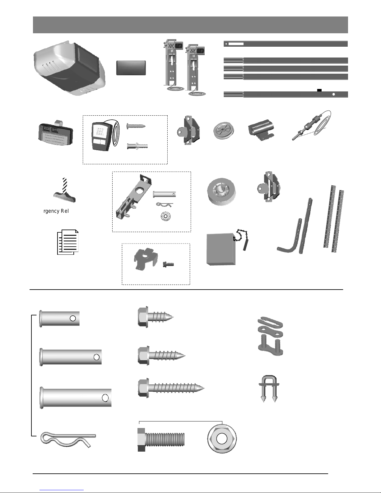
Installation hardware
shown in actual size
Table of Contents
3
— Door arms / Mounting Opener
x 2
Clevis Pin — Pulley
3/8” x 1-3/4”
Hitch Pin — Locking Clevis Pins
x 4
Lag Screw #12 x 1”— Photo Eye System
Lag Screw 5/16” x 1-1/2”
— Header Bracket / Mounting Opener
Bolt 5/16” x 1” 5/16” Flange Nut
x 4
x 4
x 4
x 4
x 1
x 1
Emergency Release Handle
+ Rope
Literature + Safety Labels
Header
Bracket
Trolley
Door Arms
Rail — Header Segment
Rail — Middle Segments x3
Hanging
Brackets
x 2
Self-Threading Screw 1/4” x 5/8”
Door Bracket
Rail — End Segment with Trolley Stop Bolt
Clevis Pin — Door arms
5/16” x 1”
Clevis Pin — Header Bracket
5/16” x 1-1/2”
Pulley
Trolley Shaft
and Cable
Sprocket
Door Bracket
INSTALLATION HARDWARE, LOCATED IN HARDWARE BAG (SHOWN IN ACTUAL SIZE 1:1)
Chain
Inventory
x 30
Insulated Staples
— Securing wires
Master Link Set
—Trolley Shaft
x 1
Rail Bracket
x 5
x 1
x 1
Drywall Anchor
x 2
x 2
Screw #6 x 1”
Wall Panel
Handheld
Transmitter
Photo Eye Safety System
Opener Unit + Lamp Dome
Cover Plate
Sprocket Cover
x 1

4
Tools Required
Sectional Garage Door
BEFORE Beginning Installation:
1. Disable locks and remove all ropes connected to the
garage door.
2. Perform the following door test to ensure your door is
balanced and in good working condition.
To Test Your Garage Door
1. Raise and lower the door to check if there is any sticking or
binding.
2. Check for loose hinges, damaged rollers, frayed cables and
damaged or broken springs.
3. Lift the door approximately halfway and release. The door
should stay at the point under proper spring tension.
Call a qualified garage door service technician if your door binds,
sticks or is unbalanced.
!
WARNING
To prevent SERIOUS INJURY or DEATH:
- Before beginning installation of the Opener please complete the following test to ensure that your door is
balanced and in good working condition.
- A poorly balanced door can cause serious injury and damage to the Opener.
- Always have a qualified garage door service technician make any required adjustments and/or repairs to
your door before proceeding with installation.
- DISABLE ALL LOCKS and REMOVE ALL ROPES connected to the garage door BEFORE installing
and/or operating the Opener.
To prevent damage to the door and Opener:
- DO NOT connect power until instructed.
- Operate this Opener with AC 120V/60Hz power supply ONLY.
Preparation
Level
Tape Measure
Hack Saw
Pencil
Drill, 3/16” and 5/16” Drill Bits
Step Ladder
Screwdriver
Hammer
Adjustable Wrench
Ratchet with
5/16”, 7/16” and 1/2” sockets
Pliers
Rubber Mallet
5
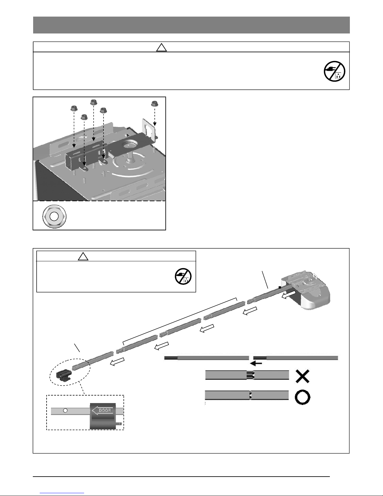
Attaching the Rail Bracket
Place the Rail Bracket on the top of the opener as shown in
Fig.1. Secure the bracket firmly using 1/4” flange nut x 5.
To Assemble Rail and Opener
1. Prepare the rails as shown in Fig.2.
2. Connect the rails starting with the Header Segment. Insert
the tapered ends into open ends, apply any additional force
necessary by tapping the Rail on padded flooring. Ensure
the End Segment has Trolley Stop Bolt facing up. Make
sure the rails are securely joined together as shown.
3. Slide the Trolley onto the rail from the Header Segment.
Make sure the arrow is pointing towards the door as shown
in Fig.2.
4. Connect the rail assembly to the Rail Bracket on the
Opener.
!
WARNING
To prevent SERIOUS INJURY:
- DO NOT connect power until instructed.
- Keep hands and fingers clear from sprocket during operation.
- Wear gloves when installing chain/belt and cable.
- Keep hands and fingers away from joints and possible sharp edges.
Trolley direction (Top View)
!
CAUTION
- DO NOT connect power until instructed.
- To prevent INJURY, keep hands and fingers
away from joints and possible sharp edges.
- Wear gloves when installing chain/belt and cable.
When connecting the rails ensure they are securely connected as shown above.
To apply additional force tap gently on the end of the rail with a rubber mallet*.
*Only use a soft rubber mallet to tap on the end of the rails as other tools may
damage your rail.
Rail — Header Segment
Rail — Middle Segments
(tapered) x 3
Rail — End Segment (tapered)
with Trolley Stop Bolt
Fig.2
Loosely connected
Securely connected by applying force
Rail and Trolley Assembly
Fig.1
1/4” Flange Nut x5
6
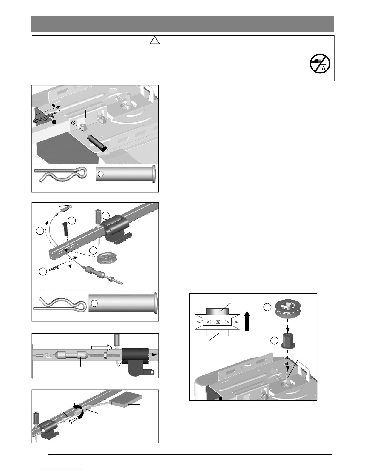
To Secure the Rail on the Opener
With the End Segment of the rail fully inserted into the Rail
Bracket, insert a 5/16” x 1-1/2” Clevis Pin through the hole and
lock it into position with a Hitch Pin as shown in Fig.1.
To Assemble the Header Section of Rail
Follow steps shown in Fig.2:
1. Remove the “Trolley Shaft and Cable” from the Chain carton
and lay it beside the rail assembly. Hold Cable Eyelet on the
end of cable and thread about 20” (50cm) through the slot
on the Header Segment of the rail.
2. Temporary insert a screwdriver to the hole on the rail apart
from the slot, slide the trolley to the screw driver and keep
the position.
3. Insert the Pulley into the opening while the cable is hanging.
4. Secure the Pulley by inserting the 3/8” x 1-3/4” Clevis Pin
through the top of the rail.
5. Lock the Clevis Pin with a Hitch Pin. Rotate the Pulley to
ensure it spins smoothly.
Slide the Trolley Shaft into the Trolley until a “click” is heard
when they are connected and locked, as shown in Fig.3.
To Link Cable with Chain
Refer to Fig.4. Place the chain carton beside the rail, hold the
“Chain to Cable Connector” and pull about 8” (20cm) of chain
from the box. Thread the Chain to Cable Connector onto the
Trolley Shaft so that they are loosely linked together.
!
WARNING
To prevent SERIOUS INJURY:
- DO NOT connect power until instructed.
- Keep hands and fingers clear from sprocket during operation.
- Wear gloves when installing chain/belt and cable.
- Keep hands and fingers away from joints and possible sharp edges.
Fig.1
Clevis Pin
Pulley
Hitch Pin
Clevis Pin — 3/8” x 1-3/4”
Hitch Pin
Fig.2
Fig.4
Fig.3
1
4
5
3
Trolley Shaft
Trolley Shaft
Trolley
Cable Eyelet
Loosely link together
Trolley Shaft
Chain-to-Cable Connector
Chain
2
Installing the Chain
Fig.5
Connect shaft to Trolley with “click”
Clevis Pin - 5/16” x 1-1/2”
Hitch Pin
Hitch Pin
Clevis Pin
Rail Bracket
Screwdriver
UP
Sprocket
Bearing end
Plastic end
Motor
Shaft
1
2
To Attach Sprocket
1. Attach the Sprocket Adaptor to the Motor Shaft.
2. Attach the Sprocket upon with the metal bearing facing the
ceiling.
Sprocket
Adaptor
7
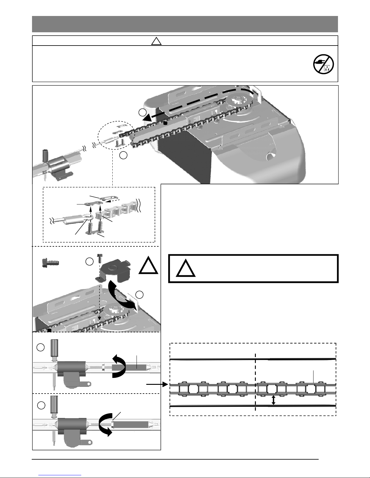
To Connect and Tension the Chain
Follow steps shown in Fig.1 to connect & tighten the chain:
1.
2.
3. After the chain is connected properly, attach the Sprocket
Cover to the opener with the self-thread screw provided.
!
WARNING
To prevent SERIOUS INJURY:
- DO NOT connect power until instructed.
- Keep hands and fingers clear from sprocket during operation.
- Wear gloves when installing chain/belt and cable.
- Keep hands and fingers away from joints and possible sharp edges.
Screw # 8x3/8”
3
4
Tighten until...
Chain to Cable Connector
5
6
Tighten nut
Flange Nut
Installing the Chain
1
Master Link
Link Cap
Spring Clip
Cable Eyelet
2
Open end of chain
Base of Rail
1/4” (6mm)
Mid-point of rail assembly
Chain
Top of Rail
Actual Size
x 1
!
THE SPROCKET COVER MUST BE
SECURELY INSTALLED!
!
4. With the trolley positioned against the screwdriver, pull the
remaining chain straight along the rail and engage chain
teeth around the sprocket. (Make sure the chain is not twisted
around the rail.)
5. Rotate the Shaft Linker towards the Trolley Shaft until the
chain is slightly loose about 1/4” (6mm) above the base of the
rail, referring to the actual-sized illustration below.
6. Tighten the Flange Nut on Trolley Shaft against the
Chain to Cable Connector.
7. Remove the temporary screw driver holding the position of
the trolley.
8
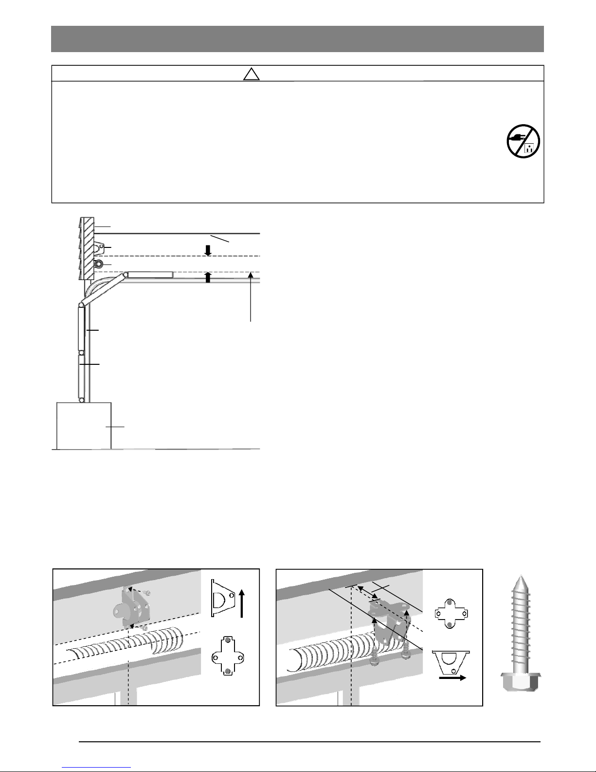
To Install Header Bracket
Note: Installation procedures may vary according to door
type.
1. While inside your garage, close the door and mark the
vertical centerline of the garage door. Extend the line onto
the header wall above the door spring.
2. Open the door to the highest point of travel. Mark a line on
the header wall 2“ (5cm) above the highest point of travel.
Note: DO NOT install the Header Bracket over drywall. In some
installations, it may be necessary to install a 2x4 across two wall
studs to create a suitable location for the Header Bracket.
If installing into masonry, use concrete anchors (not provided).
Wall-Mounting
As shown in Fig.2, place the Header Bracket on the vertical
centerline in direction shown.
Mark and drill two 3/16” holes. Fasten the Header Bracket
securely to a structural support using two 5/16” x 1-1/2” Lag
Screws.
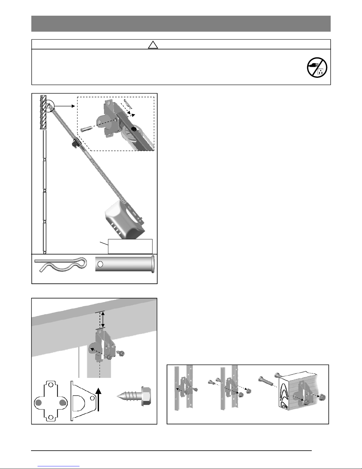
Alternative Ceiling-Mounting
Ceiling-mounting is suggested ONLY when clearance is minimal.
Extend the vertical centerline onto the ceiling as shown in Fig.3.
Center the Header Bracket on the vertical mark, no more than
6” (15cm) from the header wall. Mark and drill holes to fasten the
Header Bracket securely to a structural support.
Fig.1
Ceiling
Header Bracket
Header Wall
2” (5cm) clearance
Door Track
Door
Highest Point of Door Travel
Support block on floor
Door Spring
UP
OPENER
MAX. 6” (15cm)
H
i
g
h
e
s
t
P
o
i
n
t
o
f
D
o
o
r
T
r
a
v
e
l
Vertical Centerline
H
o
r
i
z
o
n
t
a
l
L
i
n
e
F
i
n
i
s
h
e
d
C
e
i
l
i
n
g
Lag Screw
5/16” x 1-1/2”
!
WARNING
To prevent SERIOUS INJURY:
- DO NOT connect power until instructed.
- The Header Bracket MUST be SECURELY fastened to the structural support on the mounting wall or
ceiling, otherwise the door may not reverse when required. DO NOT install the Header Bracket over drywall.
- Concrete anchors MUST be used when mounting the Header Bracket into masonry.
- NEVER try to loosen, move or adjust garage door springs, cables, Pulleys, Brackets, or hardware, all of
which are under EXTREME tension.
- Contact a qualified garage door service technician if your door binds, sticks or is unbalanced. An unbalanced
door might not reverse when required.
Vertical Centerline
Fig.2 (Wall-Mounting) Fig.3 (Ceiling-Mounting)
Mounting Header Bracket
9
!
CAUTION
To prevent SERIOUS INJURY:
- DO NOT connect power until instructed.
- REINFORCEMENT is recommended for fiberglass, aluminum or lightweight steel garage doors BEFORE
installing the door Bracket. Contact your door manufacturer for reinforcement options.
Fig.1
Fig.2
Fig.3
Carton
Clevis Pin - 5/16” x 1-1/2”
Hitch Pin
Self-Threading
Screw - 1/4” x 5/8”
UP
Vertical Centerline of Door
(a) (b) (c)
2-4” (5-10cm)
T
o
p
E
d
g
e
o
f
D
o
o
r
To Attach the Opener to the Header Bracket
1. As shown in Fig.1, use the packaging carton as temporary
support for the Opener. Place the Opener on carton to
prevent damage.
2. Align the mounting hole on the header rail to the mounting
hole on the Header Bracket.
3. Connect the Header Rail and the Door Bracket together
with a 5/16” x 1-1/2” Clevis Pin and lock it in place with a
Hitch Pin.
To mount the Door Bracket
Note: Some door reinforcement kits may provide direct
attachment of the door arm to the reinforcement bracket. If you
have a door reinforcement bracket with this option, skip this step
and proceed with the next step “Mounting Opener to Ceiling”.
1. Position the Door Bracket on the centerline of the door
approximately 2” - 4” (5-10cm) below the top edge of the
door, as shown in Fig.2.
2. Depending on the construction of your door, install using
one of the steps shown if Fig. 3 below:
For steel / lightweight doors with vertical steel
reinforcements / factory reinforced.
(a) Mark and drill two 3/16” holes. Make sure not to drill
through the garage door. Secure the Door Bracket with two
1/4” x 5/8” Self-Threading Screws (provided) as shown in
Fig.3(a).
(b) Alternative installation: Drill two 5/16” holes through the
door. Secure the Door Bracket using two 5/16” Bolts, lock
washers and nuts (not provided) as shown in Fig.3(b). The
length of bolts will depend on the thickness of your door.
Wood door
(c) Mark and drill two 5/16” holes through the garage door.
Secure the Door Bracket using two 5/16” carriage bolts,
washers and nuts (not provided) as shown in Fig.3(c). The
length of bolts will depend on the thickness of your door.
Note: DO NOT use Self-Threading Screws on a wood door.
Attaching Rail to Header Bracket and Mounting Door Bracket
 Loading...