

Page 1
Installation Instructions
and
Owner’s Manual
READ THIS MANUAL CAREFULLY BEFORE BEGINNING INSTALLATION
Installer: Permanently attach manual to the wall.
Model DCS2
BSOMU06A-1
Page 2
2
Electrical Rating
Input AC 220V~240V 50/60Hz
Current ~1A
Power ~200W
Standby power <1W
(Upon door is fully stopped and courtesy light is off)
Motor
Type DC 24V Brush
Max. capacity 800Nmm
Operation
Lifting capacity 35kg
Travel rate 150mm/s approx.
Door Type
Max. Door Size 16m
2
Travel/Force Adjustments Digital controls
Courtesy Light
Light bulb LED array
Lighting time 4.5 minutes
Transmitter
Frequency 433MHz
Operation range 50m (open-field)
Coding type Fixed-code
Battery 12V (A23 Alkaline) x 1
Safety and Features
Soft opening and closing
Safety reverse on closing and stop on opening
Miscellaneous
Operating temperature -20
o
C to +50oC
Dimension (mm) 411 L x 212 W x 175 H
Weight 5kg approx.
Accessories (Optional)
Wall Push Button (Standard / Illuminated / Wireless)
Wireless Keypad
1 / 2 / 3 / 4 Button Transmitters
Safety Photo Eye System
Specification
Page 3
3
Read and Follow These Important Safety Instructions
You will see Warning and Caution statements on the following Pages.
Read and follow these safety instructions carefully. Failure to do so could result in serious personal injury or death.
Warning means that severe injury or death may result from failure to follow instructions
Caution means that property damage or injury may result from failure to follow instructions
Be sure to read and follow all instructions carefully.
To reduce the risk of electric shock, this equipment has a grounding type plug, that has a third (grounding) pin.
This plug will only fit into a grounding type outlet. If the Plug does not fit into the outlet, contact a qualified
electrician to install the proper outlet. Do not change the plug in any way.
Check to make sure the garage door is properly installed and balanced. Garage door & parts are under
extreme tension and under no circumstance should you attempt to adjust on your own. Have a qualified
garage door service person make repairs to cables, spring and other hardware before installing the opener.
Install Entrapment Warning Label next to control button. Read the Control Adjustment Warning Label. Install
Emergency Release Tag to the Emergency Release Cord. Mount the Emergency Release Knob 180cm from the
floor. Use the manual release only to disengage the trolley. Do not use the Red Release Cord and Knob to pull
door up or down. If possible, use the Emergency Release only when the door is closed.
Do not connect opener to power source until instructed. Install door opener 210cm or more above floor.
After installing opener, the door must reverse when it comes in contact with a 5cm high object. Check this safety
feature often.
REMOVE ALL ROPES CONNECTED TO THE GARAGE DOOR.
DISENGAGE ALL EXISTING GARAGE DOOR LOCKS TO AVOID DAMAGE TO THE GARAGE DOOR.
Fiberglass, aluminum and steel doors must be reinforced to prevent damage. Consult with manufacturer for
recommendations.
All installation and wiring must be done in strict compliance with local and state building and electrical codes.
Connect the power cord to a properly grounded outlet only. Do not in any way alter or remove the grounding pin.
Photo Eye System must be installed properly. Guardian Operators recommend Photo Eye System is installed on
every garage door for your added protection. Opening doors must not close and Closing doors must open once
the beam is broken. See the test procedure page 16.
Locate push button within sight of garage door, away from all moving parts and out of reach of children (minimum
150cm above floor). To reduce the risk of injury to persons, use this operator only with a sectional door.
Never operate the opener if the system is not operating properly.
Always disconnect electric power before making repairs or removin g cover.
Activate opener only when the door is in full view and free from obstructions.
No one should enter or leave the garage while the door is moving. Do not allow children to play near, or operate
the door. Keep the remote control away from children.
After Installation is complete fasten this manual near the garage door. Perform periodic safety checks and
recommended maintenance and adjustments.
NEVER GO UNDER A STOPPED, PARTIALLY OPEN DOOR.
Test door opener monthly. The garage door MUST reverse on contact with a 5cm high object (or a two by 4 board
laid flat) on the floor. After adjusting either the force or the limit of travel, retest the door opener. Failure to adjust
the opener properly increases the risk of severe injury or death.
For products having an emergency release, when possible, use the emergency release only when the door is
closed. Use caution when using this release with the door open. Weak or broken springs are capable of
increasing the rate of door closure and increasing the risk of severe injury or death.
KEEP GARAGE DOORS PROPERLY BALANCED. See owner’s manual. An improperly balanced door increases
the risk of severe injury or death. Have a qualified service person make repairs to cables, spring assemblies, and
other hardware.
SAVE THESE INSTRUCTIONS.
!
Page 4

4
Product Features
1. Motor: Permanent Magnet Direct Current 24V DC Brush Motor.
2. Opener Lights: Turn on and off automatically with 4.5 minutes illumination for your safety and convenience.
3. Sensing System: A built-in sensing system detects obstructions during door operation. If in the Downward (close)
travel mode, the Opener will sense an obstruction and reverse to the full open position. In the Open mode, the
Opener will stop. In both cases the operator will beep continuously for 20 seconds. Since all doors are different, the
Sensing System has independent adjustments for customizing the level of force for the normal opening and closing of
specific door.
4. Close Limit positioning: In winter months it’s common for small pieces of ice or packed snow to be trapped under the
door. Ground swelling may also effect the close limit setting of the Opener. The Close Limit Switch overrides the
Sensing System under the last one (5) cm of closing travel and prevents the door from reversing if it encounters an
obstruction at this point. In case, it’s about time to shovel the snow or re-adjust the close limit higher.
5. Emergency Release: A pull cord allows manual disconnect and operation of door during power failure. Unit will
automatically reconnect when release is reset (the trolley release lever is snapped back to its original position), power
is restored and Opener is activated.
6. Mechanical Door Lock: When properly adjusted, opener locks door in closed position preventing unwanted entry.
7. Easy Connect Continuous Monitor Entrapment System: System allows quick and easy installation of “Silent Guard”
Photo Eye System while control circuitry monitors these devices continuously for proper operation.
8. Constant Contact to Close: For utmost safety if Photo Eye system fails constant contact of mechanical push button is
necessary to close door. In this mode of operation, a radio transmitter cannot be used to close door.
9. Momentary Contact to Close: Single touch to Radio Transmitter or Wall Button will allow door to close as long as
Silent Guard Photo eye system is operational.
10. Photo Eye System: An invisible infra-red beam of light guards the door opening and reverses a downward moving
door if the beam is broken by a stationary or moving object. If the beam is broken, the opener will beep for 20
seconds. Motor control circuitry constantly monitors the Photo Eye System for proper operation.
11. Digital Radio Control: Built in allowing over 1.6 million private codes, easily selected without use of tools. Bright
transmitter LED indicates operation and monitors battery condition.
12. Auto Force Learning: After setting the Up Limit and Down Limit is complete the door will run once from the Up Limit to
the Down Limit the data from this is stored in the memory. The red and green LED turn off and the opener beeps 3x,
the learning is then complete.
13. Soft Open/Close: The door soft open/close for a distance of 20-30cm depending on the size of the door being lifted.
14. Security Switch: When the Security Switch is activated the Door will not be able to operate. Signal from the Wall Box,
Transmitter, Push Button, and Up/Down button are all ignored. Light button will continue to function normally.
Page 5
5
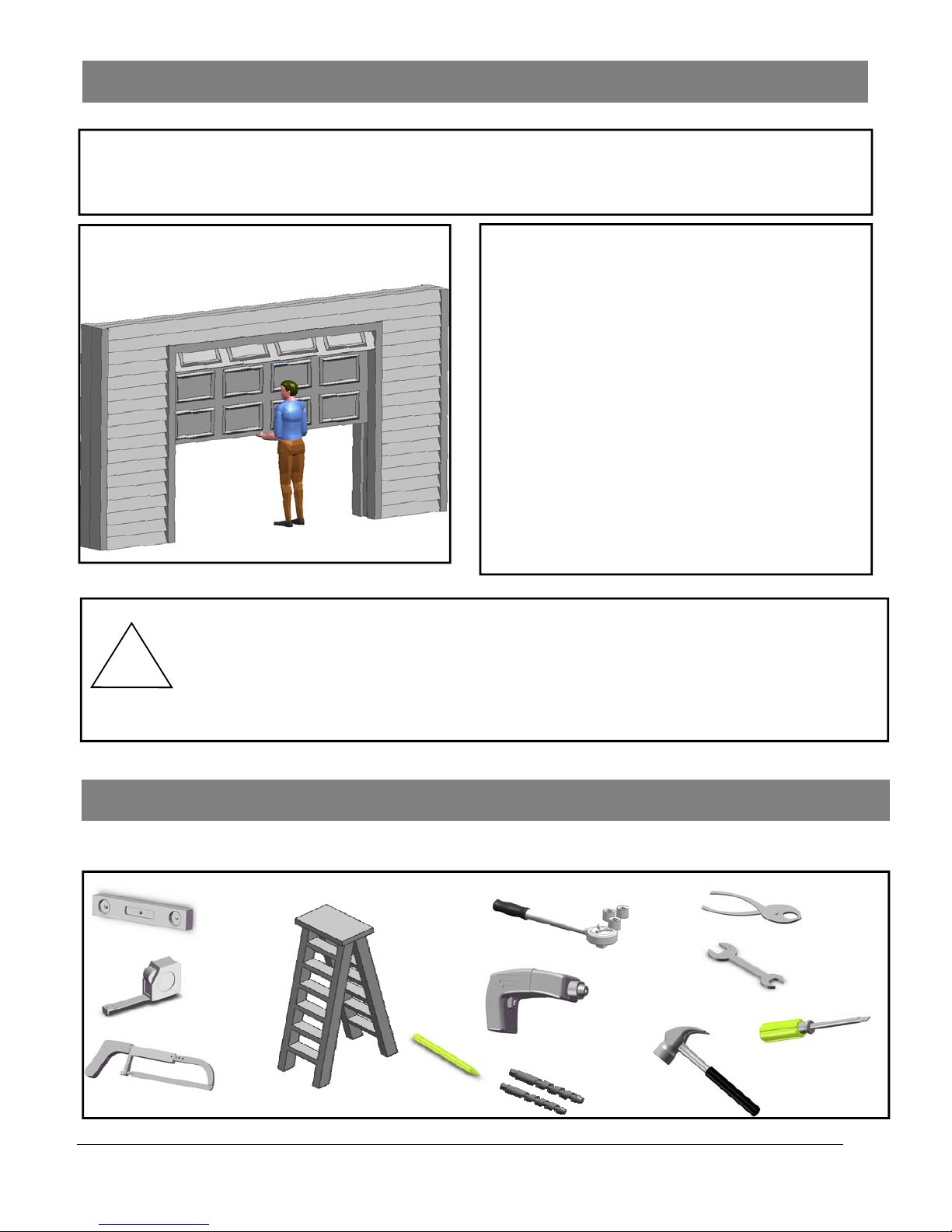
1. Raise and lower the door and check closely for areas of
sticking and binding. Check for loose hinges, wobbly
rollers, frayed cables and damaged or broken springs.
Contact a qualified garage door service person to make
the necessary adjustments.
2. Lift the door approximately halfway. When released,
the door should stay in that position. If door pulls open
or moves downward, the spring mechanism is not
adjusted properly. Contact a qualified garage door
service person to make the necessary adjust ments.
3. When properly installed and adjusted the door will
remain clear of the opening, when allowed to rest at its
natural full open position. If door drifts up or down the
door is not adjusted properly. Contact a qualified
garage door service person to make the necessary
adjustments.
Door Test
Before beginning installation of the operator please complete the following test to insure that your door is balanced and
in good working condition. A poorly balanced door could cause severe personal injury and damage to the opener.
Always have a qualified garage door service person make any needed adjustments and/or repairs to your door before
proceeding with installation.
Do not install the opener until these adjustments and repairs have been made.
Sectional Door
!
Carefully follow the instructions for the assembly and installation of the garage door opener
contained in this manual
Tools Required for Assembly and Inst allation
Level
Tape
Measure
Hand Saw Step Ladder
1/2” and 7/16”
Socket and
Wrench
Pencil
3/16” and
5/16” Drill
Drill
Pliers
Open End
Wrench
5/16” and
1/4”
Claw Hammer
Screw Driver
Page 6
6
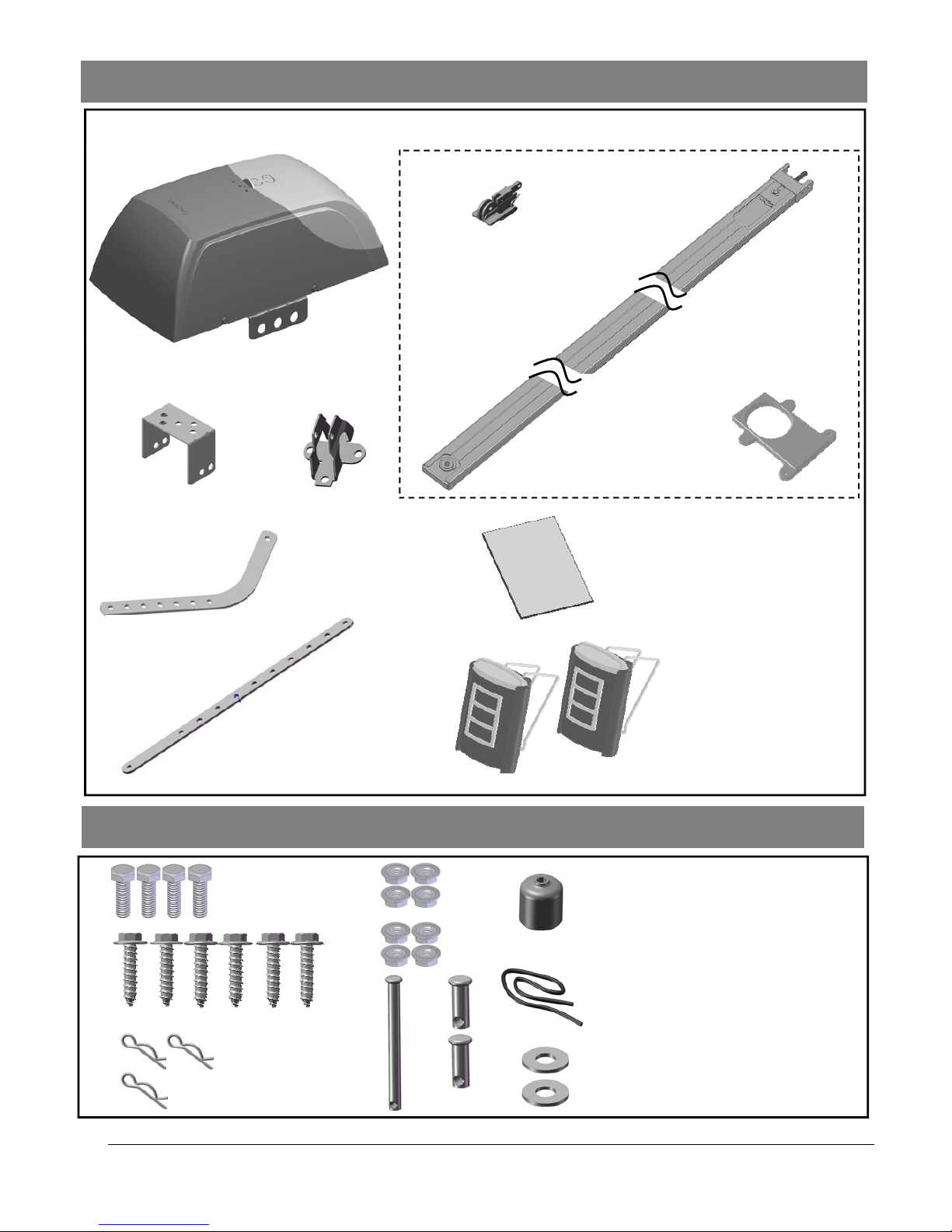
(01) Hex Bolt 5/16”18x1 (4 pcs)
(02) Lag Screw # 5/16- 9x2” (6 pcs)
(03) Hitch Pin (3 pcs)
(04) Flange Nut 1/4”-20 (4 pcs)
(05) Flange Nut 5/16”-18 (4 pcs)
(06) Clevis Pin Long (1 pcs)
(07) Clevis Pin Short (2pcs)
(08) Rope Knob (1 pcs)
(09) Rope (1 pcs)
(10) Washer(2 pcs)
(3)
(2)
(1)
Components Identification and Inventory
Fastener (parts in screw bag) Identification
(4)
(5)
(6) (7)
(3)
(5)
(4)
(6)
(01) Power Head
(02) Header Bracket
(03) Door Bracket
(04) Door Arm: Curved
(05) Door Arm: Straight
(06) Warning Label
(07) Remote Control
(08) Trolley
(09) Rail Assembly
(10) Rail support
(8)
(9)
(10)
(1)
(2)
(10)
(9)
(8)
(7)
Page 7
7
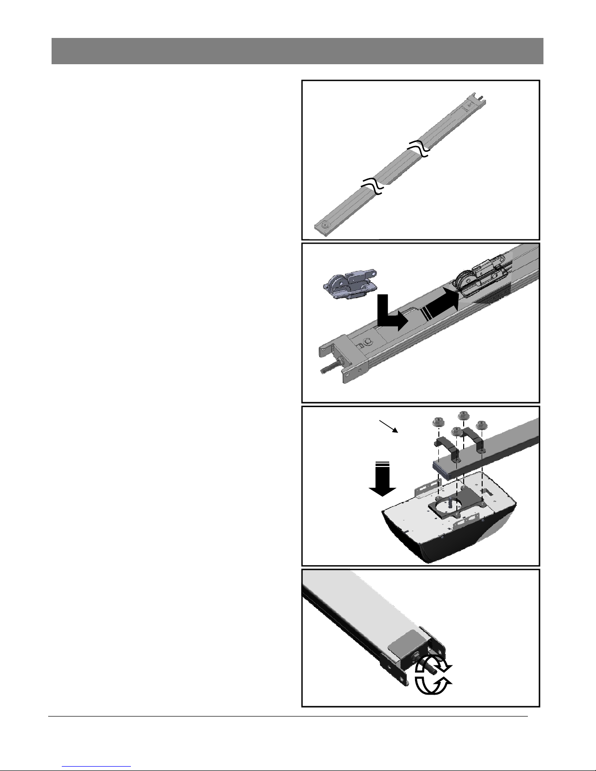
01
STEP 1.
Remove packing materials.
STEP 2.
Insert trolley (see fig.2).
STEP 3.
Place the rail support on the power head. Align rail and
power head and slide rail over drive shaft & retaining lugs.
Fasten with 4 nuts.
STEP 4.
Adjust the tension of belt at end rail. Turn clockwise to
tighten and counterclockwise to loosen.
NOTE: improper tension will result in abnormal opener
operation.” (3-4 turns clockwise is recommended)
02
1
04
03
2 . 1/4” -20Hex Flange
Nuts (4)
1
Assembly 01
Tighten
Loosen
2
Page 8

Page 9

Page 10

Page 11

11
18
Assembly 05
17
STEP 17.(OPTIONAL)
Put signal wires through the hole on the up right side.
STEP 18.(OPTIONAL)
Pull out the signal wires from hole of the front side
Page 12

12
Interface
Ground
IR
Push Button
Photo Eye Selection
Jumper off = Selected
Fig. 1 (Floor Mount)
Fig. 2
From one of
the Photo Eye
From the
other one
#12 x 1”
Lag Screw
Loosen
Inside
Garage
Door Track
6” max. above floor
Alignment
Alignment
Inside
Garage
Door Track
Alternative Floor-mounting
1. Place the Photo Eyes facing each other on each side of
the garage door, as shown in Fig.2.
2. If attaching to concrete, secure the photo eyes using
concrete anchors and bolts (not provided).
3. If necessary, align the Photo Eyes by loosening the wing
nut.
To Connect Photo Eye Safety System
1. Connect a pair of wires from either one of the Photo Eyes
to a pair of “PHOTO EYE” terminals on the rear of the
Opener as shown in Fig. 3.
2. Repeat above step to connect the other Photo Eye.
Page 13

13
!
WARNING
To prevent SERIOUS INJURY or DEATH from improper Force Adjustment:
- DO NOT adjust force to compensate binding or sticking of the garage door. Call a qualified garage door
service person to make necessary adjustments in case of binding.
- DO NOT increase force beyond minimum force required for closing the door. Too much force will cause
improper operation of safety reversal mechanism.
- After ANY adjustments, Safety Reverse Test MUST be performed to ensure the door reverses on contact
with a 5cm high object.
Travel Limit Adjustment— I. UP Limit
Desired UP limit
I. Setting UP Limit
1
2
3
4
About Travel Limit Adjustment
Limit Adjustments regulate the fully-open (UP limit) position and
fully-closed (DOWN limit) position, at which the door will stop
when opening and closing.
Make sure the trolley is engaged before proceeding
adjustments.
I. Setting UP Limit
1. Press “LIMIT” button once to enter Travel Limit
Adjustment. “UP” indicator (green) is on*.
*NOTE: Once you have pressed and released the “Limit”
button, the “UP” light will stay for 10 seconds for you to
press the “UP” button and begin programming. If the “UP”
light goes out before you are finished you need to start
over.
2. Press & hold the “UP” button, the door travels up. You may
use both “UP” or “DOWN” buttons to inch-adjust the door
to the desired UP limit position.
3. Make sure there is enough clearance for your vehicle(s),
and there is a minimum 2“ (5cm) gap between Trolley and
Stop Bolt.
4. Once the door is at the desired UP limit position, press
“LIMIT” button once, “OK” indicator (orange) flashes and
goes off. The UP limit is set.
NOTICE: This opener will not work until you set the travel limits and the travel force
adjustment. The opener will beep 5 times if it is operated without
programming.
Stop Bolt
Trolley
Minimum 2” (5cm) clearance
DOWN
FORCE
LIMIT
UP
DOWN
UP
OK
SET
PB
DOWN
FORCE
x1
LIMIT
UP
DOWN
UP
OK
SET
PB
DOWN
FORCE
LIMIT
UP
DOWN
UP
OK
SET
PB
Page 14

14
!
WARNING
To prevent SERIOUS INJURY or DEATH from improper Force Adjustment:
- DO NOT adjust force to compensate binding or sticking of the garage door. Call a qualified garage door
service person to make necessary adjustments in case of binding.
- DO NOT increase force beyond minimum force required for closing the door. Too much force will cause
improper operation of safety reversal mechanism.
- After ANY adjustments, Safety Reverse Test MUST be performed to ensure the door reverses on contact
with a 1.5” high object (2x4 laid flat).
Travel Limit Adjustment— II. DOWN Limit
Desired DOWN limit
Flashes and off
II. Setting DOWN Limit
1
2
3
CAUTION: WHILE SETTING THE DOWN LIMIT, CAREFULLY
WATCH DOOR TRAVEL DISTANCE. RELEASE BUTTON
WHEN THE DOOR MAKES CONTACT WITH THE GROUND!
II. Setting DOWN Limit
1. Following UP limit setting, press “LIMIT” button twice to
enter DOWN-limit setting. “DOWN” indicator (red) is on*.
*NOTE: Once you have pressed and released the “LIMIT”
button, it will stay for 10 seconds for you to press the
“DOWN” button and begin programming. If the “DOWN”
light goes out before you are finished you need to start
over.
2. Press & hold the “DOWN” button, the door travels down.
You may use both “UP” or “DOWN” buttons to inch-adjust
the door to the desired DOWN limit position.
3. Once the door is at the desired DOWN limit position, press
“LIMIT” button once, “OK” indicator (orange) flashes and
goes off. DOWN limit is set.
Both “UP” and “DOWN” (green and red) indicators are now on,
indicating that both UP and DOWN limits are set, and the
opener is ready for Auto Force Adjustment, see Page19.
NOTICE: The opener will not work until you set the travel limits and the travel force
adjustment.
DOWN
FORCE
x2
LIMIT
UP
DOWN
UP
OK
SET
PB
DOWN
FORCE
LIMIT
UP
DOWN
UP
OK
SET
PB
DOWN
FORCE
LIMIT
UP
DOWN
UP
OK
SET
PB
Page 15

15
!
WARNING
To prevent SERIOUS INJURY or DEATH from improper Force Adjustment:
- DO NOT adjust force to compensate binding or sticking of the garage door. Call a qualified garage door
service person to make necessary adjustments in case of binding.
- DO NOT increase force beyond minimum force required for closing the door. Too much force will cause
improper operation of safety reversal mechanism.
- After ANY adjustments, Safety Reverse Test MUST be performed to ensure the door reverses on contact
with a 1.5” high object (2x4 laid flat).
Auto Force Adjustment
Following limit-setting, the unit is now ready to
automatically adjust the forces for opening and closing the
door. Proceed with the following steps to complete
adjustment.
1. With both “UP” and “DOWN” indicators are on after Travel
Limit Adjustment, press the “FORCE” button once to enter
Auto Force Adjustment.
2. The door will travel up automatically (I) and stop at UP
limit for 2 seconds (II). Door will then travel down
automatically (III) and stop at down limit (IV).
3. The “OK” indicator (orange) will flash with beeps, the Auto
Force Adjustment is completed.
2s
Stops at DOWN limit
Travels up
Stops at UP limit for
2 seconds
Travels down
I II
III
IV
x2
Flashes
OK
1
2
3
Auto Force Adjustment
FORCE
x1
LIMIT
UP
DOWN
DOWN
OK
SET
PB
UP
Page 16

16
2x4 Board Laid Flat
Warning: The Sensitivity System Reversing Test should be performed monthly to ensure that
this important system remains in proper adjustment
Testing the Safety Reverse System
Warning: Failure to Test Reversing System Could Result in Death or Serious Injury. Test This
System Once A Month.
To test the Opener Reversing Feature at floor level place a
solid object 5cm thick on the ground so that the center of the
door will come into contact with it. Close the door. If the close
force adjustments are correct, the door will reverse within one
and a half seconds upon contacting the object and travel to
the full open position. The door will emit short beeps
continuously for 25 seconds. If this does not occur, re-check
Limit Adjustments on pg.12 and Force/Sensitivity Adjustments
pg.13.
Note: Any time any adjustments are made to Limits or Sensitivity, You must retest the opener for the Reversing
Feature at floor level as outlined above.
Testing the Photo eye system
Start the door down and then place an obstacle approximately
20cm high by 30cm wide in the path of the beam. The Red
Pilot Light on the Silent Guard Photo Eye System should go
off. The door should stop for 1-1/2 seconds and reverse to the
full open position. The Opener will emit long beeps
continuously for 20 seconds. If the door is moving up and the
beam is broken, the door will continue up to full open. With
the door fully open and at rest, place the obstacle in the path
of the beam once again. Activate the Wall Push Button, The
Opener will revert to and remain in the Up limit position. Hold
the Wall Push Button to close the door (door will beep while it
travels to the down limit position).
*Auto Close Timer is only available with the Photo Eye
System present.
Warning: A damaged or malfunctioning Photo Eye System can enable a garage door to close
on people or property, causing serious injury or even death. Perform this test
monthly to ensure proper operation.
NOTE: If the garage door travels more than 5cm in a downward path after releasing the button, the Silent Guard
Photo Eye System is malfunctioning. Check all electrical connections and alignment of the Photo Eye System.
!
!
Invisible Light
Beam Protection
Sensor Beam 1015cm above Floor
Sensor Beam 1015cm above Floor
Page 17

17
1. To program transmitter, press “RADIO SET” button, “OK” LED flashes twice. The unit is ready
to accept a transmitter within a 30 seconds time frame.
2. Press any button on the transmitter within 30 seconds.
3. “OK” LED flashes once and operator beeps twice, acknowledging the transmitter is set.
x2
To DELETE ALL transmitters :
Press and hold “SET” button for about 7 seconds until “OK” LED flashes and beeps twice.
Programming the Remote Controls
DOWN
FORCE
LIMIT
UP DOWN
UP
OK
SET
PB
DOWN
FORCE
LIMIT
UP DOWN
UP
OK
SET
PB
DOWN
FORCE
LIMIT
UP
DOWN
UP
OK
SET
PB
Page 18

18
Make Sure That:
1. The front and rear mounts for the opener are sound and secure and the rail is positioned correctly above the
high arc of the door and that the opener is positioned over the door action centerline.
2. For sectional doors and tilt doors, the position of the door arm with the opener closed, is such that its connecting
point on the trolley is 12cm to 20cm behind its connecting point on the door bracket. The door arm should never
be perfectly vertical when the door is in the closed position (there should be an angle of 15-20°).
3. The emergency release knob and cord are secured to the emergency release lever on the trolley. The knob is
located 180cm above the floor and requires no more than 20kgs pull to actuate. The trolley and release
mechanism are properly lubricated. Recommend: Silicone based lubricant
4. The standard push button is in such a position and at such a height that it can only be actuated by an adult. The
caution label is prominently displayed next to the push button.
5. All wiring is correct to code. There is ground continuity in the supply. The ground prong on the power cord is
intact.
6. All ropes have been removed from the door, and any lock mechanisms removed or disabled. The door moves
freely without binding when operated manually. The door is correctly balanced and lubricated. All door hardware
is secure and sound. The sensitivity has been adjusted to minimum force. The appropriate warning sticker has
been affixed to the door.
7. The door reverses on obstructions to within 5cm of the floor. The floor beneath the closed door provides uniform
contact.
8. The manual is attached to the wall near the push button.
9. On doors with extension type springs, safety restraint cables have been installed through the springs.
10. There is surge protection on the power line to the opener.
***Guardian Operators recommend photo eyes to be installed on all garage doors for added sa fety***
Final Installation
Page 19

19
1. Never permit children to play with or operate the garage door opener either from the wall station or the remote
controls. Keep radio transmitter locked in the car. Misuse of the push button or transmitter could result in serious
injury or even death.
2. Open the garage door with the remote controls only when the garage door is fully visible to you and clear of all
obstructions. The garage door should be kept in sight until it is completely open or closed and you are certain that the
garage door opener has shut off.
3. Attempting to exit the garage through the garage door opening, while the door is in motion, is a very dangerous
activity that could result in serious injury or even death.
4. Children and pets should always be clear of the door opening while the garage door is in motion.
5. Check the safety reverse mechanism at least once a month to make sure that it will reverse with the minimum amount
of force. Also check to be sure that the door will reverse within 5cm of the floor. See p.14.
6. Check the manual operation of your garage door at least every 90 days to be sure that it is operating smoothly and
does not bind or stick. Tighten all bolts on the door and visually check all hardware including springs for wear of
damage. Caution: If service is needed contact your local garage door service person.
7. Do not decrease the safety reversing sensitivity mechanism to overcome a damaged or poorly operating door. This
will adversely affect the operation of the safety reverse mechanism which could result in damage to the door,
personal injury or even death.
Caution: Never operate the door opener if the reversing mechanism is not functioning properly.
8. Whenever possible, the manual disconnect should only be used when the door is fully closed. Caution: Extreme care
must be taken whenever the disconnect cord is pulled with the door partially open. Weak or broken springs may allow
the door to fall rapidly resulting in property damage, personal injury or death. If a broken spring is evident, contact
your local garage door service person immediately before disconnecting the door from the opener. Never attempt
servicing a broken spring.
9. Always disconnect electrical power supply to the opener when performing any maintenance or service to the opener
or garage door. Failure to do so could result in electrical shock, property damage, personal injury or death.
10. If any damage to any mechanical or structural component of the opener is observed, discontinue use and contact
your local garage door service person immediately.
11. If the door auto reverses, please ensure there is no obstruction to the track or door.
After the Installation
Page 20

20
Rail and Hardware Parts List
A-1
Housing Assembly
A-2 Dome Cover A-3 LED Light
A-4 Logic Board A-5 Logic Board Holder A-6 RPM Reader
A-7 Motor A-8 Transformer A-9 Standby Power Module
A-10 LED Light Cover A-11 Chassis A-12 Power Cord
A-13 Rail Support
A-10
A-2
A-4
A-1
A-12
A-11
A-8
A-7
A-6
A-9
A-3
A-5
A-13
Page 21

 Loading...