

Page 1
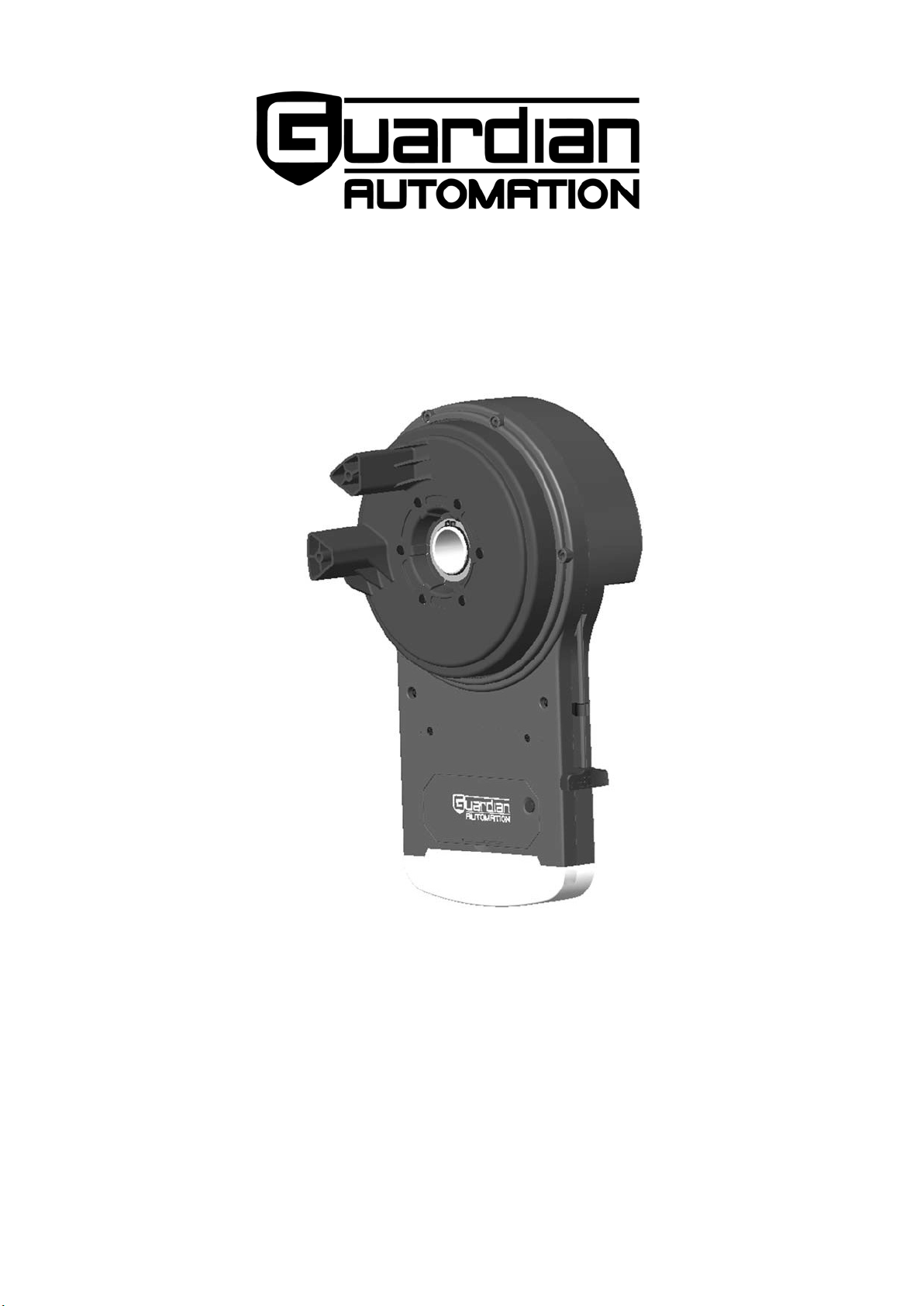
DCR2
ROLLER DOOR OPERATOR
Installation Instructions
and
Owner’s Manual
READ THIS MANUAL CAREFULLY BEFORE BEGINNING INSTALLATION
Installer: Permanently attach manual to the wall.
HSOMU03A-1
Page 2
2
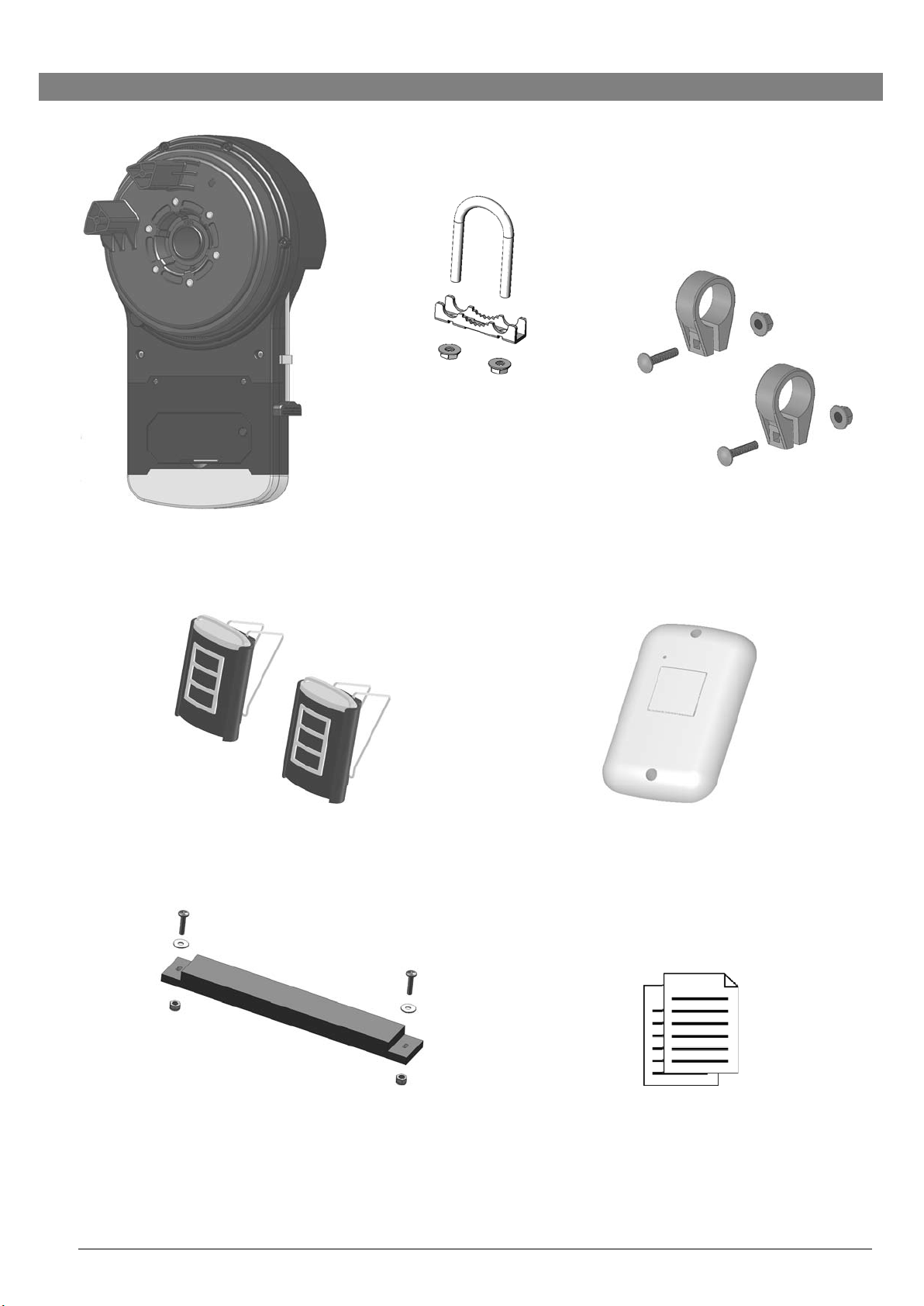
Inventory
U-bolt + Saddle x1 set
Anti-Coning Clip x2 sets
Operator Unit
Remote Handset x2 * Wireless Wall Button x1 *
Weight Bar & mounting screw set x1 Manual + Safety Label
*
Optional Accessories
*
Items and quantity may differ to images shown
Page 3

3
DCR2 Specification
Electrical Rating
Input
AC 220V 50/60Hz
Max. Current
2A
Power
100W
Standby Power
<2W
Motor
Type
DC 24V
Max. Capacity
1000N
Recommended Lifting Forces
Max. Lifting Force
60kg
Rated Lifting Force
40kg
Door Type
Max. Door Size
20.5m
2
Max. Door Height
4.6m
Door Travel Limits
4.5 turns of door drum approx.
Courtesy Light
Light Source
6 x Ultra Bright LEDs
Lighting Time
2.5 minutes
Transmitter
Frequency
433MHz
Operation Range
50m (open field)
Coding Type
Fixed-code
Battery
12V (A23 Alkaline) x 1
Features
Soft opening and closing
Safety reverse on closing and stop on opening
Digital interface for RH/LH setting, force adjustment, etc.
Miscellaneous
Operating Temperature
-20oC ~ +50oC
Dimension (mm)
434 L x 248 W x 190H
Weight
5.4kg approx.
Page 4

4
Table of Contents
Pre-Installation Notes 4
Important Notices 5
Installation Instructions 6
Connectors 7
Setting Direction of Operation 8
Setting UP-Limit 9
Setting DOWN-Limit 10
Sensitivity Auto-Learning 11
Manual Sensitivity Adjustment (For Installers Only) 12
Programming Transmitter 13
Setting Auto-Closing Timer 14
Trouble-Shooting 15
Parts Breakdown 16
Parts List 17
Warranty 18
Pre-Installation Notes
The operator may be fitted to either the RIGHT or LEFT hand side of the roller door.
Check that there is sufficient side clearance to fit the operator unit as below listed:
Door Type
Minimum side clearance
“A” Series (1) (25mm deep tracks)
90mm
“AA” Series (2) (50mm deep tracks)
115mm
All doors with Windlock Tracks subject to Drum Position
140mm
Ensure there is a properly earthed mains supply socket adjacent to where the operator is to be fitted.
If the operator is being fitted at the same time as the new door installation, read these instructions in
conjunction with the door installation instructions.
If the operator is being retro-fitted, make sure the door operates smoothly and is properly balanced.
N.B.: SPECIAL CARE SHOULD BE TAKEN IF RE-TENSIONING OF THE DOOR IS REQUIRED.
Page 5

5
Important Notices
IMPORTANT: PLEASE READ THESE INSTRUCTIONS CAREFULLY PRIOR TO
COMMENCING THE INSTALLATION OF THE OPERATOR UNIT.
CAUTION
DANGER
CAUTION
CAUTION
DANGER
This Automatic Operator has been designed to provide years of trouble-free
use.
READ THESE IMPORTANT SAFETY RULES FIRST
Keep the garage door balanced. Sticking or binding doors must be repaired.
Garage door, door springs, brackets and their hardware are under extreme
tension and can cause serious personal injury. Do not attempt adjustment. Call for
professional garage door service.
Do not wear rings, watches or loose clothing while installing or servicing a garage
door operator.
Installation and wiring must be in compliance with your local building and
electrical codes. Connect the power cord only to properly earthed mains.
The safety reverse system test is very important. Your garage door must
reverse when obstructed on closing. Failure to properly adjust the operator may
result in serious personal injury from a closing garage door. Repeat the test once
a month and make any needed adjustments. (See Sensitivity adjustment).
This unit should not be installed in a damp or wet space.
Push the Emergency Release handle to disengage the motor drive ONLY when
the drive is switched OFF and, if possible, when the door is fully closed.
Do not use the sensitivity adjustments to compensate for a binding or sticking
garage door. Excessive sensitivity will interfere with the proper operation of the
Safety Reverse System or damage the garage door.
Disengage all existing garage door locks to avoid damage to garage door.
Install any additional Push Buttons in a location where the garage door is visible,
but out of the reach of children. Do not allow children to operate push button/s or
remote control/s. Serious personal injury from a closing garage door may result
from misuse of the operator.
CAUTION: Activate operator only when the door is in full view, free of
obstructions and the operator is properly adjusted. No one should enter or leave
the garage while the door is in motion. Do not allow children to play near the door.
Disconnect electric power to the garage door operator before making repairs or
removing covers.
IMPORTANT: Fix the caution label supplied to the rear of the garage door as a
reminder of safe operating procedures.
NOTE: 1. When you disengage the unit, please move the door gently.
2. Direction of operation (L/R) must be set correctly before operation.
IF THERE IS ANY PROBLEM PLEASE CONTACT YOUR LOCAL
SUPPLIER OF THIS OPERATOR
!
!
!
Page 6
6
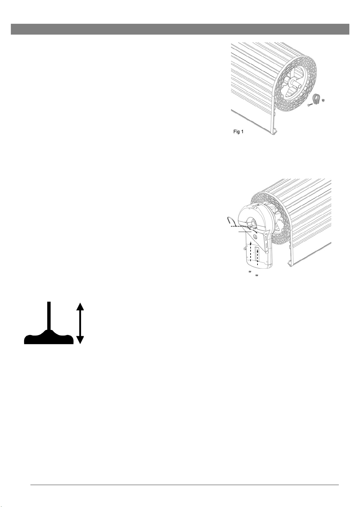
Installation Instructions
1. Fit anti-coning collar TIGHT TO SHAFT against drum at
opposite end of curtain to the motor using anti-coning clip
supplied in kit as shown in Fig.1.
2. Ensure the door curtain is pinned to the drum wheel.
Pinning is the screwing of the curtain to the door drum
wheel.
3. Roll up door with at least 100mm of curtain hanging down
in the tracks.
4. Ensure that the U-bolt on the end of the door opposite the
end to which the operator is to be fitted is tightened
securely. This U-bolt holds all the spring tension on the
door once the other U-bolt is released.
5. Slide drive unit onto shaft as shown in Fig.2. Ensure the
drive forks engage fully with the narrowest spoke on drum
wheel.
6. For ease of installation, the sun gear can be disengaged
for free rotation by pushing the Emergency Release
handle downwards. To re-engage and lock the sun gear,
push the handle upwards.
Caution: Operator must be ENGAGED before
proceeding further installation.
Fig.1
Fig.2
Emergency Release
PUSH—ENGAGE OPERATOR
PULL —DISENGAGE OPERATOR
Page 7

7
Connectors
I. Main Control Panel
LED Indicators
UP RADIO SET
FORCE
GND
Photo Eye Selection
Jumper off — Selected
Ext. Aerial
DC 24V
Jumper on — Unselected
Photo Eye
Push Button
Manual Operate
Button
II. Miscellaneous Control and Terminals
Auto-Close Timer
LED Light
Backup Bat-
* Auto Close Timer function will only work when Photo Eye System is properly installed.
To activate Auto-Close Operation
Turn the knob towards “ + ” for maximum delay time of
2.5 minutes.
To deactivate Auto-Close Operation
Turn the knob fully towards “- ”.
WARNING: This operator system is equipped with an unattended operation feature
when Photo Eye System is applied. The door could move unexpectedly.
NO ONE SHOULD CROSS THE PATH OF THE MOVING DOOR!
_
OFF + 2.5 min
!
Page 8

8
Setting Direction Of Operation
For using the operator the first time, it is necessary to set the direction of operation.
1.
Connect power supply; both “UP” and “DOWN” LEDs are on.
2.
Initialize the operational direction by pressing “UP” or “DOWN” button for the correct
direction setting according to the illustrations below. The corresponding LED is on
upon key input.
View View
3.
Press “RADIO SET” button to confirm setting. The “OK” LED is on with 2 beeps.
x2
Caution: Make sure the drive unit is set for the correct side of installation!
To reset installation direction, press the “LIMIT” button constantly until both “UP”
and “DOWN” LEDs are ON, repeat steps 2 and 3 to set the appropriate direction.
UP RADIO SET
FORCE
UP RADIO SET
FORCE
UP RADIO SET
FORCE
Page 9

9
Setting UP Limit
1.
Press “LIMIT” button once to enter limit-setting mode. “UP” LED is on.
2.
Press & hold the “UP” button, release the “UP” button when the door reaches
the desired up limit position.
3.
During limit-setting mode, press “UP” or “DOWN” to fine-tune to desired UP
limit position.
or
4.
When the door is at the desired UP limit position, press “LIMIT” button once,
“OK” LED flashes and goes out. UP limit is set.
UP RADIO SET
FORCE
UP RADIO SET
FORCE
UP RADIO SET
FORCE
UP RADIO SET
FORCE
Page 10

UP RADIO SET
FORCE
Setting DOWN Limit
1.
Press “LIMIT” button twice to enter DOWN-limit setting. “DOWN” LED is on.
2.
Press & hold the “DOWN” button, release the “DOWN” button when the door
reaches the desired down limit position.
3.
During limit-setting mode, press “UP” or “DOWN” to fine-tune to desired down
limit position.
or
4.
When the door is at the desired DOWN limit position, press “LIMIT” button
once, “OK” LED flashes twice and both “UP” and “DOWN” LEDs are on.
DOWN limit is set and the operator is ready for Sensitivity Auto-Learning.
10
UP RADIO SET
FORCE
UP RADIO SET
FORCE
UP RADIO SET
FORCE
Page 11

11
Sensitivity Auto-Learning
Following limit setting, the unit is now ready to learn the sensitivity for door
travel automatically. Proceed with the following steps to complete installation.
1. Both “UP” and “DOWN” LEDs are on after limit-setting, press the “FORCE”
button once to enter Sensitivity Auto-Learning mode.
2. The door will open and stop at UP limit for 2 seconds.
3. Door will then close and stop at down limit. The operator will beep 3 times; sensitivity
is learnt automatically, acknowledging that the sensitivity has been set.
X3
UP RADIO SET
FORCE
Page 12

UP RADIO SET FORCE
UP RADIO SET FORCE
UP RADIO SET FORCE
Manual Sensitivity Adjustment (For Installers Only)
To adjust UP Force
1.
Press “FORCE” button once, “UP” LED is on. You are now in “UP Force Setting” mode.
2.
To increase or decrease UP force by pressing “UP” or “DOWN” button once at a time, a
beep sound indicates an increase or decrease for one increment, and 2 beeps upon upper
level 8 or lower level 1 is reached. The UP Force is default at level 5.
3.
To complete “UP Force” setting, press “FORCE” button. “UP” LED goes off and “OK” LED
flashes once with 2 beeps. “UP Force” setting is completed.
1 2
Enter Force Setting / UP
— or +
3
x2
To adjust DOWN Force
Confirm
1.
To adjust DOWN force, press “FORCE” button once, “UP” LED is on, then press “FORCE”
button again within 5 seconds, “DOWN” LED is on, you are now in “DOWN Force Setting”
mode.
2.
To increase or decrease DOWN force by pressing “UP” or “DOWN” button once at a time, a
beep sound indicates an increase or decrease for one increment, and 2 beeps upon upper
level 8 or lower level 1 is reached. The DOWN Force is default at level 1.
3.
To complete “DOWN Force” setting, press “FORCE” button. “DOWN” LED goes off and
“OK” LED flashes once with 2 beeps. “DOWN Force” setting is completed.
1
Enter Force Setting Select DOWN Force
2
3
x2
— or +
12
Confirm
UP RADIO SET FORCE
UP RADIO SET FORCE
UP RADIO SET FORCE
UP RADIO SET FORCE
Page 13

13
Programming The Transmitter
1. To program a transmitter, press “RADIO SET” button, “OK” LED flashes twice.
The unit is ready to accept a transmitter within a 30 seconds time frame.
2. Press any button on the transmitter within 30 seconds.
3. “OK” LED flashes once and operator beeps twice, acknowledging the transmitter is
set.
x2
To DELETE ALL transmitters:
Press and hold “SET” button for about 7 seconds until “OK” LED flashes and
beeps twice.
UP RADIO SET
FORCE
UP RADIO SET
FORCE
UP RADIO SET
FORCE
Page 14

14
Setting Auto-Closing Operation / Courtesy Light / Buzzer Responses
Auto-closing timer is turned off as default (the screw control is at fully “-”)
1.
Optional Photo Eye* must be selected and properly connected and aligned to enable Auto
-Closing Operation. (* Contact your local operator supplier)
2.
Turn the screw towards ‘+’ position to set to appropriate delay time (max. 2-1/2 minutes)
for the door to auto-close after fully opened.
Photo Eye must be selected and connected
3.
When the delay time is reached within the door at fully open position, the operator beeps
twice and closes the door automatically.
1
2
3
x2
Courtesy Light / Beeper Responses
Operation / Condition
Courtesy Light / Beeper Responses
Operator is initially plugged-in (no travel limits stored)
Flash x 5
Reconnecting power (with travel limits stored)
Flash x 3
“RADIO SET” button is pressed
Beep x 1
Upon activation
Light On for 2.5 minutes
Upon activation by remote transmitters
Beep x 1, Light On for 2.5 minutes
Remote Transmitter / Keyless Entry PIN code accepted
Beep x 2
Operator is triggered without programming
Beep x 5
Door travels with abnormal speed
Beep x 12 (1 beep / second)
Photo Eye System is obstructed during door-closing
Beep x 20 Medium Beep
The door is obstructed during travel
Beep x 25 Rapid Beep
Photo Eye Selection
Jumper off — Selected
Jumper on — Unselected
UP
RADIO SET FORCE
4
Page 15

15
Trouble - Shooting
DOOR WILL NOT OPERATE FROM
A)
Control Panel on the Unit
» Check power, the courtesy light should flash upon re-connecting power.
» IF NOT, check mains plug and fuse.
» The Manual release is engaged.
» Operation Direction (L/R) is set correctly.
» Limits are correctly set, i.e. UP Limit for fully open position, DOWN Limit Switch for fully closed position.
» Disengage and move the door manually to half-closed position, re-engage and try again.
» Try operation with Handheld Transmitter.
B)
On Handheld Transmitter
» Check door operates correctly using the manual operate button on the unit to prove the system is okay.
» Try re-programming Transmitter.
» Check battery in Transmitter is correctly fitted, and the LED should illuminate upon key-press.
» Try new battery.
» Move aerial and try in different orientations, keeping away from steel structures and electrical cables.
DOOR OPERATES BUT FAILS TO FULLY OPEN OR REVERSES BEFORE CLOSING
» Check manual operation for correct balance, not binding. Adjust if necessary.
» Spray silicone lubricant into tracks. Do not grease.
» Check/adjust safety sensitivity setting.
» Check Limits.
BANGS HARD ON TRACK STOPS WHEN FULLY OPEN
» Check UP Limit setting.
» Adjust if necessary.
BANGS HARD ON GROUND AND REVERSES WHEN FULLY SHUT
» Check DOWN Limit setting.
» Adjust if necessary.
DOOR FAILS TO TRAVEL DOWN FROM OPEN POSITION - MOTOR RUNS AND ROLLER DOOR CURTAIN
BALOONS
» Check door curtain has smooth line of entry into tracks, as near vertical as possible.
» Check door tension is not too great, reduce spring tension it necessary.
» If the above does not cure the problem, then the door may require a weight bar to be fitted.
SHORT RANGE REMOTE CONTROL
» Check battery is correctly fitted in Transmitter.
» Try new battery.
» Move aerial and try in different orientations, keeping away from steel structures and electrical cables.
DOOR OPERATES BUT FAILS TO FULLY OPEN BUT REVERSES TO CLOSED POSITION
» Reset Limits.
» Re-adjust Sensitivity Adjustment.
POWER FAILURE
To disengage the operator
» Pull the manual release (red handle) downwards.
To engage the operator
» Push the manual release handle upwards.
Page 16

16
Parts-Breakdown
2
1
3
8
9
10
4
11
5
12
6
7
19
6
15
13
21
18
14
16
20
23
17
22
24
25
27
26
28
Page 17

17
Parts List
1
Enclosure
15
Control Console
2
Power Cord
16
LED Board
3
Motor
17
LED Cover
4
RPM Encoder
18
Clutch Levering
5
Transformer Mounting Plate
19
Drive Gear
6
Transformer Protection
20
Clutch Dock
7
Transformer
21
Clutch Release
8
U-bolt
22
Finger Dog
9
Saddle
23
Clutch Retainer
10
Saddle Mounting Plate
24
Sungear Driving Wheel
11
Chassis Core
25
Sun Gear
12
Chassis
26
Front Cover
13
Release Rod
27
Sungear Washer
14
Release Handle
28
Circlip
Page 18

Warranty'–'DCR2'
'
Important)document:)To)be)kept)by)the)user)of)the)Product)
)
If you are a consumer under the Australian Consumer Law, Guardian Automation will provide you, the original purchaser of this
DCR2 (Product), with this limited warranty in addition to any rights that you have under Australian consumer protection laws. This
warranty is in addition to, and does not exclude, restrict or modify your guarantees and other legal rights under
Australian Consumer law. Our goods come with guarantees that cannot be excluded under the Australian Consumer Law. You
are entitled to a replacement or refund for a major failure and compensation for any other reasonably foreseeable loss or damage.
You are also entitled to have the goods repaired or replaced if the goods fail to be of acceptable quality and the failure does not
amount to a major failure.
This warranty only applies to Product sold by Guardian Automation or an authorised dealer in Australia. An approved and
authorised dealer meaning an approved reseller of Guardian Automation’ products purchased from Guardian Automation for the
purpose of supplying those products to the end consumer. This warranty document is not intended to create a contract between
Guardian Automation and the purchaser.
Except for this warranty, Guardian Automation gives no warranties of any kind whatsoever (whether express or implied) in
relation to the Product and all warranties relating to the Product are hereby excluded to the extent permissible by law. Guardian
Automation will not accept any additional warranties or conditions provided by others, which attempt to modify the terms of this
warranty.
Subject to your non-excludable rights under the Australian Consumer Law, Guardian Automation expressly excludes any liability
for consequential loss, incidental or indirect damages (including but not limited to damages for loss of business profits, business
interruption and loss of business information) due to a defect of the Product. In particular, any loss or damage caused to other
equipment or accessories used with the Product or any loss resulting from a delay in repair, is excluded to the extent permitted
by law.
Conditions of Warranty
Subject to the terms of this warranty, Guardian Automation warrants to the original purchaser that:
1.
the Product will be free from defects in materials and workmanship for a period of 5 years from the date of purchase or
10,000 cycles (whichever occurs first) for the motor, and 3 years from the date of purchase or 6,000 cycles (whichever
occurs first) for the electronics and mechanics. A cycle means one opening and closing cycle of the door.
2.
the remote-controlled transmitters and accessories included with the Product will be free from defects in materials and
workmanship for a period of 12 months from the date of purchase.
3.
where the Product is installed by Guardian Automation, the installation service is covered for a period of twelve months
from defects in materials and workmanship.
Subject to the following conditions and any non-excludable statutory rights, Guardian Automation will, at its option, either repair or
replace any proven defects in materials or workmanship;
(a)
The garage door to which the Product is fitted must be “spring balanced” and able to be opened and closed by a force not
exceeding 15 kilograms.
(b)
Proof of purchase must be presented.
(c)
The Product must have been serviced by a professional authorised by Guardian Automation at intervals not exceeding 12
months (the cost of servicing is not covered by this warranty).
(d)
The Product is well maintained and kept in good working condition.
(e)
The supplier must be notified as soon as practicable of any defect covered by this warranty. If the Product was supplied
by an authorised Guardian Automation dealer and this dealer cannot be contacted, then notification must be made as
soon as practicable to Guardian Automation.
(f)
This Warranty is limited to Return-to-Base (RTB) repair and does not cover labour or associated costs for on-site
attendance. The purchaser is responsible for the cost of returning the Product to the supplier or to Guardian Automation.
The purchaser is responsible for the cost of labour and any travel or other additional expenses incurred for any on-site
attendance.
(g)
Any Product repaired or replaced during the warranty period will be covered by the terms of this warranty until the
expiration of the original warranty period.
(h)
Where Guardian Automation, or its Authorised Dealer, in its absolute discretion determines that a warranty claim is not
being covered under the conditions of this warranty, then Guardian Automation or its authorised dealer (as the case may
be) reserves the right to charge for reasonable reimbursement of expenses for assessing the claim, and these must be
paid by the purchaser before the Product will be returned (at the purchaser’s expense)
(i)
This warranty is not transferrable.
(j)
Repairs may be conducted using refurbished components, and Products presented for repair may be replaced with
refurbished products of similar type.
(k)
Products must be returned in original or suitably safe packaging.
(l)
This warranty is only applicable for repairs to Products in Australia.
Page 19

What this warranty does not cover:
(a)
Corrosion: Damage from salt, water or any other form of corrosion.
(b)
Installation: damage or defect due to faulty installation of the Product (except where installed by Guardian Automation).
(c)
Service: damage or defect due to a failure to properly service, care for or maintain the Product in accordance with the
instruction manual.
(d)
Damage due to misuse (including failure to follow the instruction manual) or deliberate, negligent or accidental damage
of any sort.
(e)
Modifications: Guardian Automation will not be required to incorporate any modifications made to existing or future models.
(f)
Electrical Power: Any damage, issues or faults caused by electrical surge or fluctuation.
(g)
Problems that are directly or indirectly caused by or relate to the garage door or garage door hardware, which could
include but are not limited to door springs, rollers, curtain wear, fixings and alignment.
(h)
Normal wear and tear.
(i)
Non-authorised repairs.
(j)
Acts or omissions of any person, including approved dealers, other than Guardian Automation and its staff.
(k)
Travel Expenses: Expenses incurred by Guardian Automation or its authorised dealer in travelling and or transporting
Products to and from the location of the Product are not included and will be paid for by the purchaser.
(l)
Additional access or equipment required: Expenses incurred by Guardian Automation or its authorised dealer required to
provide clear access, or the equipment used to access the Product (for example: Lifting hardware such as forklift or scissor
lift) are not covered by this warranty and must be paid for by the purchaser.
(m)
Frequency Interference: Where remote transmitters cannot operate the opener due to frequency interference at the
location where the Product is installed.
(n)
Damage due to matters outside of the reasonable control of Guardian Automation including, but not limited to,
rain, hail, flood, water, fire, insects or any other event beyond the reasonable control of Guardian Automation.
(o)
Consumer Goods: Components such as globes, accessories, batteries and other consumable parts are not covered by
this warranty.
What will void this warranty:
Guardian Automation will be relieved of all obligations, responsibilities and liabilities under this warranty if, in the opinion of
Guardian Automation, the defects in the Product result from:
(a)
Any modifications, repairs or works carried out to the Product, which are not authorised by Guardian Automation.
(b)
The fitment of any device to the Product, which is not approved by Guardian Automation.
(c)
Misuse or unreasonable use of the Product, as determined by Guardian Automation.
(d)
Any use of the Product other than for residential application only (i.e. for use in a single-family dwelling or individual
garages within an apartment complex).
(e)
Failure to follow any directions or instructions, including any warning notifications in instruction manuals or signs on or
provided with the Product.
If any part of this warranty is or becomes illegal, void or unenforceable, this does not invalidate the rest of the warranty.
How to make a claim
Please be aware you are responsible for the expense of making a claim under this warranty.
To make a claim, if the Product was supplied to you directly from Guardian Automation please forward a copy of your original
receipt as proof of purchase and a completed warranty claim form to Guardian Automation directly. If the Product was
supplied by an authorised Guardian Automation dealer, please provide the copy of your original receipt along with a
completed warranty claim form to that dealer. If the authorised dealer cannot be contacted, then please contact Guardian
Automation and provide the copy of the receipt and the completed warranty claim form and Guardian Automation will forward
these to the relevant authorised dealer.
This warranty is supplied by Guardian Automation Pty Ltd.
WARRANTY CERTIFICATE
Invoice No:
Installation Date:
Your Name:
Phone No:
Address:
State:
Installed by:
Motor Serial #:
Door Model:
Please retain this completed warranty form along with your invoice as proof of purchase to validate you claim.
www.guardianautomation.com.au
Page 20

 Loading...