

Page 1
MODEL ACS0
Residential Garage Door Opener
for Sectional and One Piece Track Garage Doors
up to 2.4M HIGH
Installation Instructions
and
Owner’s Manual
READ THIS MANUAL CAREFULLY BEFORE BEGINNING INSTALLATION
This Operator Must be installed by a Qualified Installer Only
HSOMU01A-1
Page 2

ACS0 Specifications
Electrical Rating
Input
AC 230 50Hz
Max. Current
2A
Power
375W
Standby Power
2W
Motor
Type
AC 230V Single Phase
Max. Capacity
75kg
Recommended Lifting Forces
Max. Lifting Force
60kg
Rated Lifting Force
15kg
Door travel rate
135mm/second
Door Type
Door Travel Limits
3.05 metres
Courtesy Light
Light bulb
E27 60W
Lighting Time
4.5 minutes
Transmitter
Frequency
433 MHz
Operation Range
50m (open field)
Coding Type
Fixed-code
Battery
12V (A23 Alkaline) x 1
Operation Features
Safety reverse on closing and stop on opening
Digital Force Adjustment
Auto-Closing (15/30/45s) with Photo Eye Installed
Miscellaneous
Operating Temperature
-20oC ~ +40oC
Dimension (mm)
344L x 240W x 173H
Weight
5.4kg approx.
Accessories (Optional)
Wall Push Button (Standard / Illuminated / Wireless)
Wall Control Box
Wireless Keypad
1 / 2 / 3 / 4 Button Transmitters
Safety Door Reversing System (PE)
Page 3

3
Contents
Specification 02
Contents 03
Safety Instructions 04
Before Starting 04
Pre-Assembly Check 04
Product Features/ Specifications 05
Door Test 06
Tools Required 06
Component Identification & Inventory 07
Fastener Identification 07
Assembly Instructions 08
Installation Notes 09
Step 1 Mounting the Front Bracket 09
Step 2 Attach the Rail Assembly to Front Bracket 10
Step 3 Position the Power Head for Mounting Bracket 10
Step 4 Mounting the Power Head to Ceiling 10
Step 5 Recheck all Fasteners for Tightness 10
Step 6 Door Arm, Bracket and Plate Installation 11
Step 7 Check Emergency Release 11
Step 8 Connecting Power 12
Step 9 Installing Light Bulb 12
Step 10 Installing Wireless Push Button
Step 11 Programming Transmitter Codes 12
Tilt Door Installation 13
Operation and Adjustment Instructions 15
Setting the Limits 15
Setting the Sensitivity Force 16
Testing the Openers Reversing System 17
Testing the Photo eye system 17
Final installation 18
Trouble Shooting 19
After the Installation 20
Parts Breakdown 21
Warranty 23
NOTICE
Guardian Garage Door Openers are designed and tested to offer safe operation, provided installation and use
of this product is followed in strict accordance with these instructions for assembly and installation. Failure to
comply with these instructions could cause property and/or bodily injury. The opener is intended only for the
use described in this manual and use other than intended will void any and all warranties herein described.
Page 4

4
Read and Follow These Important Safety Instructions
You will see Warning and Caution statements on the following Pages.
Read and follow these safety instructions carefully. Failure to do so could result in serious personal injury or death.
Warning means that severe injury or death may result from failure to follow instructions
Caution means that property damage or injury may result from failure to follow instructions
•
Be sure to read and follow all instructions carefully.
•
Locate lighted push button within sight of garage door, away from all moving parts and out of reach of children
(minimum 1.5M above floor). To reduce the risk of injury to persons, to use this operator only with a sectional
door.
•
Check to make sure the garage door is properly installed and balanced. Because of the extreme tension most
garage door parts are under do not attempt to adjust on your own. Have a qualified garage door service person
make repairs to cables, spring and other hardware before installing the opener.
•
Mount the Emergency Release Knob 2M from the floor. Use the manual release Only to disengage the trolley. Do
not use the Red Release Cord and Knob to pull door up or down. If possible, use the Emergency Release only
when the door is closed.
•
After installing opener, the door must reverse when it comes in contact with a 40mm high object. Check this safety
feature often.
•
Disengage all existing garage door locks to avoid damage to the garage door.
•
Aluminum and Steel Doors must be reinforced to Prevent Damage. Consult with Manufacturer for
Recommendations.
•
All installation and wiring must be done in strict compliance with local and state building and electrical codes.
Connect the power cord to a properly grounded outlet only. Do not in any way alter or remove the grounding pin.
•
Never operate the opener if the system is not operating properly.
•
Always disconnect electric power before making repairs or removing cover.
•
Activate opener only when the door is in full view and free from obstructions.
•
No one should enter or leave the garage while the door is moving. Do not allow children to play near, or operate
the door. Keep the remote control away from children.
•
After Installation is complete fasten this manual near the garage door. Perform periodic safety checks and
recommended maintenance and adjustments.
!
Page 5

5
Product Features
1.
Motor: Permanently lubricated, thermally protected, heavy-duty motor with automatic reset.
2.
Opener Lights: Turn on and off automatically with 2-1/2 minutes illumination for your safety and convenience.
3.
Sensing System: A built-in sensing system detects obstructions during door operation. If in the Downward (close)
travel mode, the Opener will sense an obstruction and reverse to the full open position. In the Open mode, the
Opener will stop. In both cases the light will start flashing and continue to flash for 60 seconds. Since all doors are
different, the Sensing System has independent adjustments for customising the level of force for the normal
opening and closing of specific door.
4.
Close Limit Switch: In winter months it’s common for small pieces of ice or packed snow to be trapped under the
door. Ground swelling may also affect the close limit setting of the Opener. The Close Limit Switch overrides the
Sensing System under the last 2.5cm of closing travel and prevents the door from reversing if it encounters an
obstruction at this point.
5.
Emergency Release: A pull cord allows manual disconnect and operation of door during power failure. Unit will
automatically reconnect when release is reset (the trolley release lever is snapped back to its original position),
power is restored and Opener is activated.
6.
Mechanical Door Lock: When properly adjusted, opener locks door in closed position preventing unwanted entry.
7.
Easy Connect Continuous Monitor Entrapment System: System allows quick and easy installation of Safety Door
Reversing System, (Photo Eye system Optional) while control circuitry monitors these devices continuously for
proper operation.
8.
Constant Contact to Close: For utmost safety if Photo Eye system (Optional) fails, constant contact of mechanical
push button is necessary to close door. In this mode of operation, a radio transmitter cannot be used to close door.
9.
Momentary Contact to Close: Single touch to Radio Transmitter or Wall Button will allow door to close as long as
Photo eye system (Optional) is operational.
10.
Safety Door Reversing System (Photo eye system Optional): An invisible infra-red beam of light guards the door
opening and reverses a downward moving door if the beam is broken by a stationary or moving object. If the beam
is broken, the opener light will flash for 30 seconds. Motor control circuitry constantly monitors the Photo Eye
system for proper operation.
11.
Digital Radio Control: Built in allowing over 1.6 million private codes, easily selected without use of tools. Bright
transmitter LED indicates operation and monitors battery condition.
Page 6
6
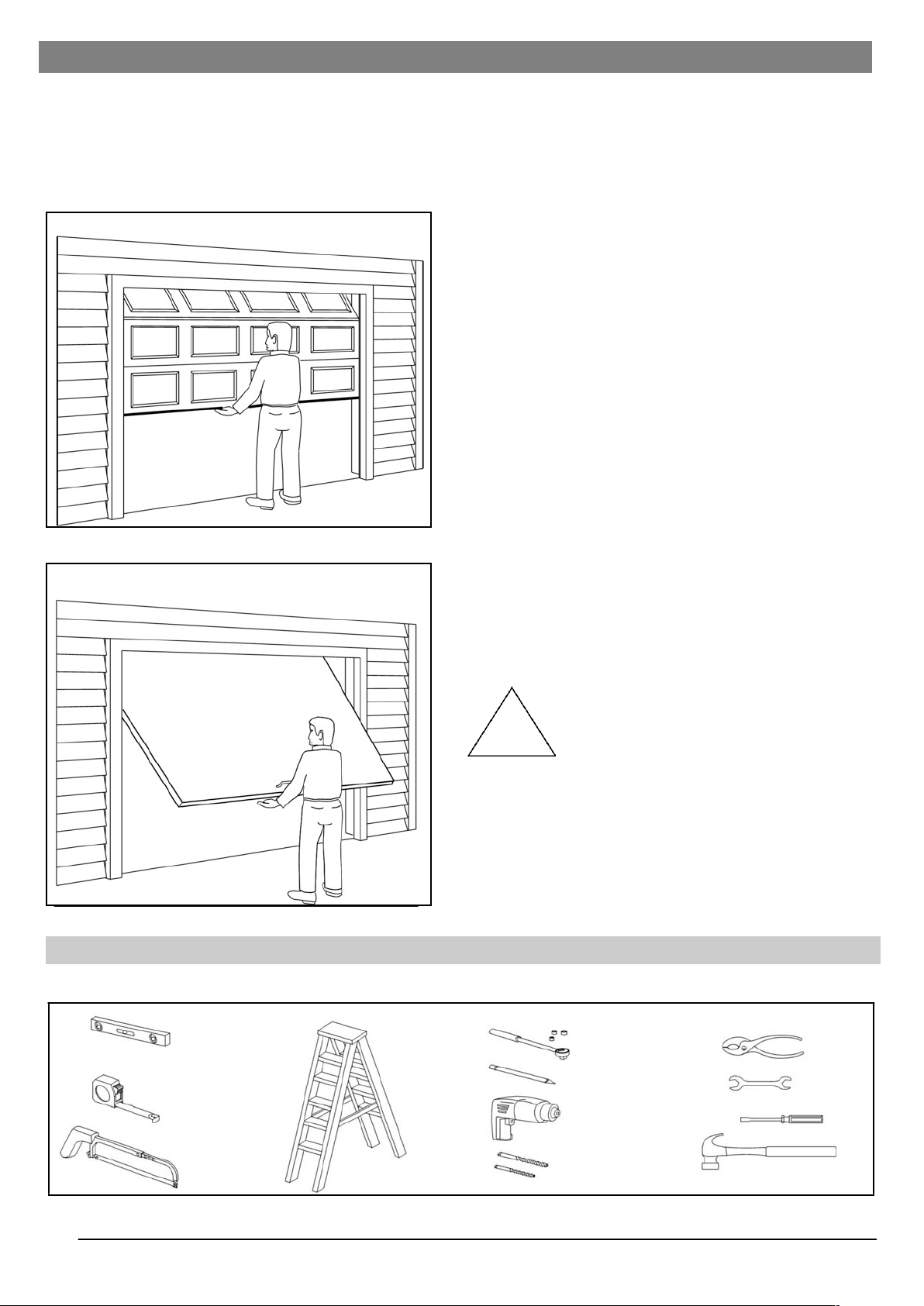
Door Test
Before beginning installation of the operator please complete the following test to insure that your door is balanced and
in good working condition. A poorly balanced door could cause severe personal injury and damage to the opener.
Always have a qualified garage door service person make any needed adjustments and/or repairs to your door before
proceeding with installation.
1.
Raise and lower the door and check closely for areas of
sticking and binding. Check for loose hinges, wobbly
rollers, frayed cables and damaged or broken springs.
Contact a qualified garage door service person to make
the necessary adjustments.
2.
Lift the door approximately halfway. When released, the
door should stay in that position. If door pulls open or
moves downward, the spring mechanism is not
adjusted properly. Contact a qualified garage door
service person to make the necessary adjustments.
3.
When properly installed and adjusted the door will
remain clear of the opening, when allowed to rest at its
natural full open position. If door drifts up or down the
door is not adjusted properly. Contact a qualified
garage door service person to make the necessary
adjustments.
Do Not Install the Opener Until These
Adjustments and Repairs Have Been Made.
Carefully follow the instructions for the assembly and
installation of the garage door opener contained in this
manual
Tools Required for Assembly and Installation
Sectional Door
One Piece Door w/ Track
!
Claw Hammer
5mm and
8mm Drill Bit
Step Ladder
Hand Saw
Screw Driver
Drill
Tape
Measure
Pencil
Pliers
Open
End
Wrench
8mm
13mm and
11mm Socket
and Wrench
Level
Page 7
7
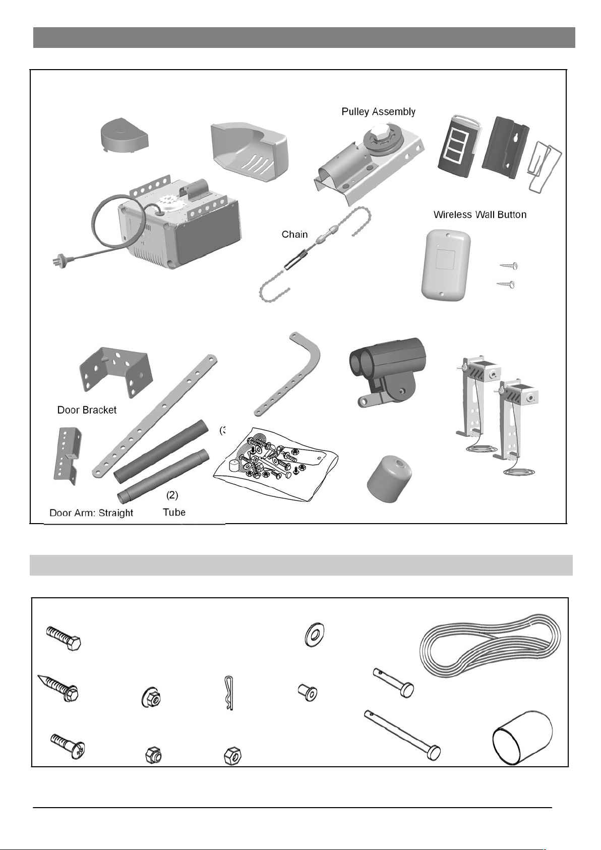
(3
Pulley Assembly
Wireless Wall
Button
Staples (20)
Door Bracket
(2)
Door Arm: Straight
Tube
Components Identification and Inventory
Fastener (parts in screw bag) Identification
Power Head w/ Sprocket Cover
Lamp Dome
Transmitter and Visor Clip
Header Bracket
Door Arm: Curved
Trolley Assembly
)
Trolley Stop
Screw Bag
Photo eye system (Optional)
Clevis Pin (1)
Long
Hex Nut (1)
6mm-20
Lock Nut (1)
8mm-18
CombHead Bolt(2)6mm-20
Rope Knob (1)
Well Nut (2)
Flange Nut (2)
8mm-18
Hitch Pin (2)
Lag Screw (6) 8mmx1-17mm
Clevis Pin (1)
Short
Rope (1)
Flat Washer (2) 8mm
Hex Bolt (3) 8mm-18x1”
Page 8
8
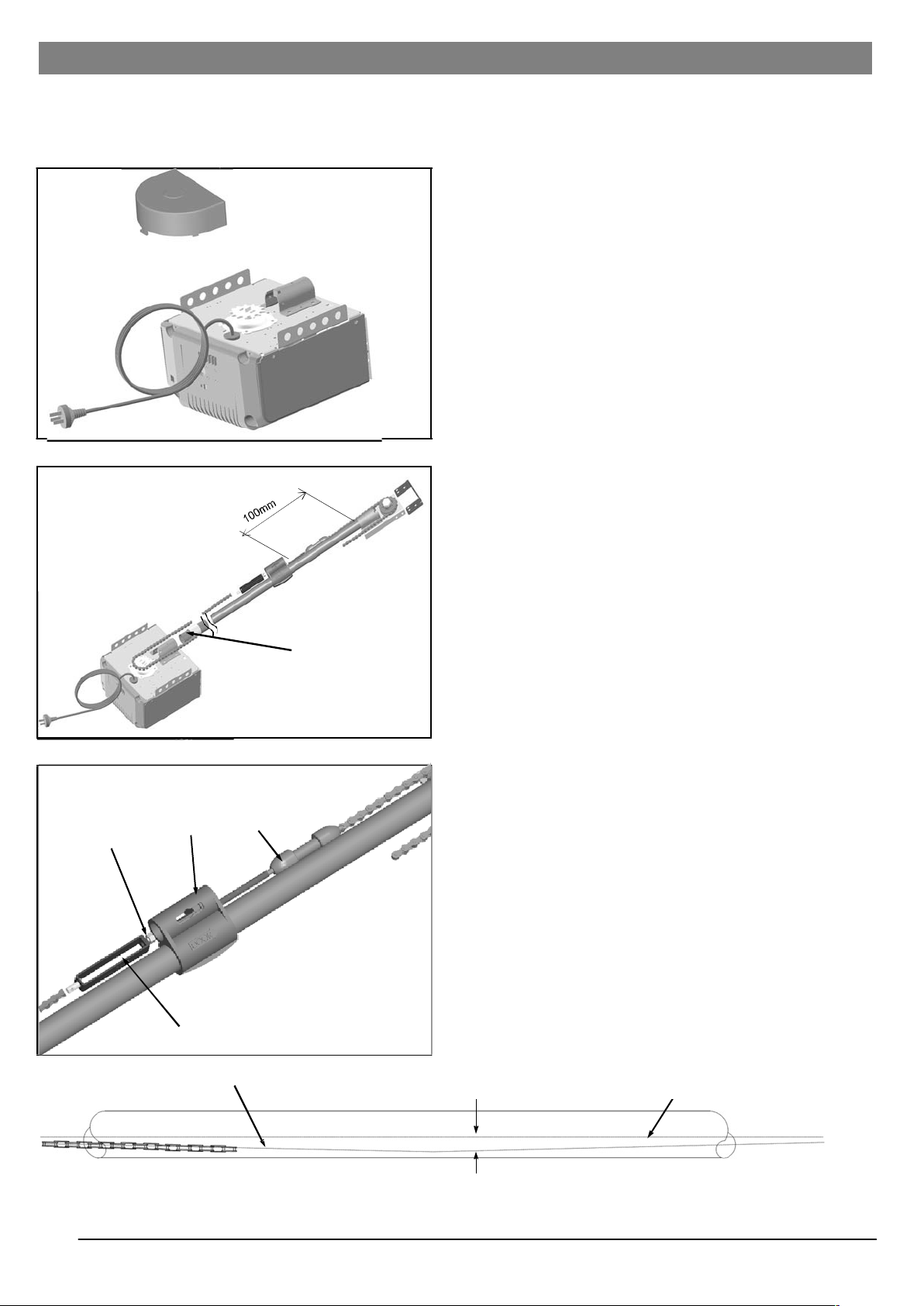
Assembly
Note: The Tube/Chain Speed Unit Assembly with Trolley and Front Idler Sprocket is packaged separately from the
Power Head Unit. Refer to Page 7 for package contents and identification.
Step 1.
Place Power Head Unit on discarded packing material/
cardboard.
Step 2.
Remove the sprocket cover, see figure 7A, and position
the trolley on the drive tube as illustrated figure 7B.
Step 3.
Roll out the chain assembly carefully to prevent tangling.
Connect the trolley release rod to the connecting link
through the drive trolley, but do not tighten. (Figure 7C)
Wrap the chain around the drive sprockets on the drive
unit ensuring the chain engages the teeth on the sprocket.
Extend the chain along the other side of the tube and
around the return pulley.
Ensure the trolley has not moved from the point as
indicated in the diagram (Figure 7B).
Now install the connecting link to the trolley release rod as
illustrated. (Figure 7C).
Note: during the assembly the trolley release rod is
actually engaged in the trolley. It is shown here removed
for the sake of clarity.
Step 4.
Tension the chain by turning the adjusting nut. Hold the
trolley release rod and the connecting link to prevent from
turning. (Figure 7C).
The tension should be correct when the chain has a sag of
between 6 mm and 12 mm (Figure 7D).
Tighten lock nut against the connecting link, to lock
adjustment into place (Figure 7C)
Note:
The chain and its supporting equipment may stretch after a
period of time. The chain should be re-tightened after the
first three months’ use, and thereafter as required.
Step 5.
Re-check all nuts for tightness.
Assembly is now completed. You are ready to begin installation of the opener.
Figure 7A
Figure 7B
Safety Spacer
Figure 7C
Lock
Nut
Trolley
Trolley
Release
Rod
Connecting
Link
Figure 7D
Centre of Chain
6 mm to 12 mm
Centre of Tube
Page 9

9
Installation
Installation procedures will vary depending on type of garage door.
Identify your garage door from those illustrated below and follow procedure outlined for your type of door.
For tilt door (one-piece door), please refer to installation on page 12&13.
To determine high point of door. Raise the door slowly, until it reaches its highest point of travel. Place support block
under the door and measure the distance from the floor to the top edge of the door. Remove block and lower door.
Sectional Door with Curved Track
One-Piece Door with Horizontal Track
Springs, Pulleys, Cables and Mounting Hardware that balance your garage door are under
tremendous pressure at all times and can cause serious injury or death if disturbed. Do not
attempt adjustment!
Step 1.
Mounting the front Bracket (Sectional Doors and Onepiece with Track.) Mark a vertical centreline on the
header above the door. By manually raising the door,
determine the high point of the doors travel (see figure
8A and 8B) and using a level, transfer this
measurement to the header (See figure 8C) Draw a
horizontal line, crossing the previously drawn
centreline, at this point. Install the front Mounting
Bracket securely with lag screws as shown below. If
necessary, reinforce the header with steel or wood to
ensure a secure mount.
Support
Block
Track Point of
Door Travel
Door
Track
Ceiling
50mm Clearance
Header Wall
Header Bracket
Figure 8A
!
Figure 8C
Pre-Drawn
Vertical Line
Pre-Drawn
Horizontal Line
Header
Header
Lag Screws
Page 10

10
Installation
Warning: Aluminum or Lightweight Steel Doors Will Require Reinforcement before installation
of door mounting brackets. Contact your door manufacturer instructions. Failure to properly do so
may result in severe door damage.
Note: Reinforcing may affect the balance of your door. Check for proper manual operation after installation. If
necessary have your door re-balanced by a qualified garage door service person.
Step 2.
Place the power unit on the floor (use cardboard packing material
for protection) and raise Mounting Bracket align. Insert 8mm x 219mm Clevis Pin and Hitch Pin. See Figure 9A.
Step 3.
Raise the opener and rest the power unit on a ladder or other
support. Open the door to the full open position. See Figure 9B.
Note: Since the opener will be secured permanently in this
position, open and close the door a few times to be sure the door
does not rub on the rail and that you have allowed the proper
clearance before proceeding.
Step 4.
Mount Power Head to Ceiling:
Since there are many different ceiling designs, all possible
mounting illustrations cannot be shown. Primary concern is to
secure the power head to the ceiling so that operational strength,
rigidity and safety are achieved. The opener must be securely
fastened to a structural support of the garage. Although there are
a series of mounting holes provided on the power unit, try to
secure the mounting hangers to the slots closest to the front.
Mounting may usually be accomplished by using standard 32mm
perforated steel angle available at most hardware stores or from
your local garage door service person. If in doubt as to location
of, and attachment to, ceiling joists, a carpenter should be
contacted to provide assistance. A cross brace will be necessary
if power head is mounted 200 mm or more from the ceiling. See
figure 9C.
Fasteners Supplied: 2 ea. 8mm-18x 48mm8 Lags, 4 ea,
8mm - 18 x 28mm Hex Blots with Lock Washers and Nuts.
Step 5.
Re-check all Lags, Nuts and Bolts for Tightness.
!
Clevis-Long
Tube
Header Bracket
Hitch Pin
Figure 9A
Page 11

!
Installation
Step 6.
Door Arm, Bracket and Plate Installation:
Install the door mounting bracket in the centre and even, with the
top set of rollers on the door as illustrated Figure. 10A. (Fasteners
Supplied: 2 ea. Lag Screw. Connect the straight door arm section
(single hole section) to the trolley using a 8mm x 25.4mm Clevis
pin and clip. The door arm must pivot freely. Connect the two
Door arm pieces so that it leans toward the power unit as
illustrated fig. 10B. Do not install the door arm so that it is straight
up and down when the door is closed or the emergency release
will not function properly. Now attach Door Arm to Trolley using
8mm x 25.4mm Clevis pin and clip.
Step 7.
Tie a double overhand knot in one end of the Emergency Release
Rope and slip the other end through the Red Release Knob, the
Release Instruction Card and the hole at the end of the Release
Lever on the Trolley (Please take time now to read and familiarise
yourself with the instructions on the Emergency Release Label)
Figure 10C. Tie a second double overhand knot in the free end,
adjusting the Rope so that the Red Knob is 2M above the floor. If
the Rope must be cut, flame seal the cut end with a match or
lighter to prevent fraying or unraveling.
Figure 10C
Release
Knob
Double
Overhand
Knot
Double
Overhand
Knot
Release
Instruction
Card
Note: The Emergency Release Mechanism is engaged by pulling
the Release Knob down and towards the door, allowing the Trolley
Mechanism to separate freeing the door. To re-engage simply
move the Emergency Release Mechanism Lever upwards and
operate the Opener using the push button or Transmitter. The two
parts will automatically reconnect.
Note: This operation should be attempted only when the door is
fully closed. Disconnection when open or partially open can cause
the door to close quickly and cause personal injury or damage to
the door.
Use Manual Release Rope to Disengage Trolley Only. Do Not Use the Rope and Knob to
Pull the Door Open or Closed
Warning: A Child Operating the Door Controls Risks Injury - Or Death to themself and to
others. Do not Allow Children to Operate Any Door Controls. Mount the Push Button at least
1.5 M from the floor out of reach of children
Warning: Improper Door Operation can Cause Injury or Death. Caution Label Must Be
Mounted on Wall near The Push Button. All Warnings Should Be Strictly Adhered To.
11
Hex Bolts
and Nuts
(2)
Lag
Screw (2)
Curved
Hitch Pin
Clevis
Pin and
Door Arm
Door
Bracket at
Centre of
Door
Door Arm
Straight
Figure 10A
Page 12

12
Figure 11A
Figure 11C
Installation
Warning: Installation & Wiring Must Be in Compliance with Local Electrical and Building Codes.
Operation at other than 240V 50 Hz Will Cause Opener Malfunction and Damage.
Step. 8
Opener must be permanently wired or plugged into a grounded
3-prong receptacle wire according to local codes, within 1M of
the Power Unit.
Step. 9
Install an A19 100W Max Rough Service Bulb (available at most
hardware stores) firmly in the light socket. Light bulbs in Door
Openers are subject to vibration during normal operation, which
may shorten their life span. Fit Light Lens Cover and snap into
place.
Step. 10 Installing the Standard Wireless Wall Button
(1)
Select a convenient place near an access door, 1.5m above
the floor and out of reach of children for mounting. (2) Mount the
Wireless Wall Button with screws supplied as shown in Figure
11A.
Step. 11 Programming Transmitter Codes
Programming Wireless Wall Button
Press the “Radio Set Button” on the opener as shown in figure
11B. The courtesy light will stay on for 30 seconds.
During this 30 second period, press the button on the Wireless
Wall Button, the courtesy light will flash twice this will indicate
that the receiver has accepted the code.
If the code is not accepted the courtesy light will stay on for 30
seconds, flash 4 times and then stay on for 2 1/2 minutes.
Programming Handset
Repeat above procedure to program handset code by pressing
the desired button you wish to program on a transmitter.
Adding Handsets
Up to 20 handset codes (including wireless keypad) can be
programmed into the receiver repeating the above process.
Each button on a handset has its own code and must be
programmed separately. In case of more than 20 codes are
programmed, the very first code will be replaced by the latest
code programmed.
Erase ALL Codes
To erase all transmitter codes from memory, press and hold the
“Radio Set Button” for above 5 seconds. The courtesy light will
then flash 7 times, indicating all codes have been erased from
memory.
!
Figure 11B
Figure 11C
Holster
Transmitter
Visor Clip
Page 13

13
Installation (Tilt Door)
Step 1:
Locate the centre of the top edge of the garage door and mark it on the inside face. With a level set plumb at this mark,
draw a vertical line on the mounting surface above the door. (IF a ceiling surface suitable for marking exists, extend the
line to the ceiling and mark the ceiling. Open the door and plumb up from the centre mark made on the door to the
ceiling, if one exists, and mark the ceiling. Determine the rise of the high arc of the door. Use level to measure rise on
mounting surface above door. Use the table below to determine the distance the front end bracket should be mounted
above the top of the door when closed.
HIGH ARC RISE MOUNTING DISTANCE
100 cm 200cm
100-200 cm 330 cm
200-300 cm 450 cm
Make the appropriate measurement and mark the
vertical line at this point.
Step 2:
Attach the bracket provided directly to the structure or the addition with lag screws or bolts and self locking nuts so that
one leg of the bracket provides a shelf upon which the front end of the rail may be rested and subsequently attached.
The leg of the bracket forming the shelf should be at the horizontal mark made in Step 1. The centre hole in this leg
should be aligned with the centre of the door opening or the vertical line. The other leg of the bracket, which is to be
attached to the structure may be above or below the mark as the situation may require.
Step 3:
Place the front end of the rail on the bracket attached in Step 2, and drop one of the 6mm x 50mm carriage bolts
through the hole in the end of the rail and the centre hole in the bracket. Run one of the 6mm nuts on the end of the bolt
a few turns. This will temporarily hold the rail in place while the back end is swung upward and rested on a step ladder.
CAUTION: IF ADDITIONAL HEIGHT IS REQUIRED, BE CERTAIN THAT THE MEANS USED PROVIDES A STURDY
AND STABLE NON-SKID PLATFORM. PULL THE CARRIER RELEASE ARM TO A VERTICAL POSITION AND
SLIDE THE OUTER HALF OF THE CARRIER TO THE REAR OF THE RAIL. THIS WILL PREVENT THE DOOR
FROM STRIKING THE LEVER. At this time the door can be opened to its high arc position. It will be
necessary to support the door so that it will remain in this position. Position the rail over the centre of the top
section of the door.
Lower the back end of the operator so that the bottom of the rail is about 13mm above the door edge at the high arc
position (Fig 13A). Do not allow the door to support the operator, as this will cause a false measurement to be taken
and possibly damage the door. Support the operator in the same fashion as before and measure the distance from the
ceiling to the selected frame mounting slot. The length of the rear vertical supports will not be greater than this
dimension.
Step 4:
A rear mount must be constructed to secure the rear of the operator to the ceiling. The distance from the operator to the
ceiling structure has already been determined in STEP 3. Measure and cut the appropriate length of perforated angle
iron or other suitable metal required to suspend the operator. The operator frame plate is 165mm wide. The vertical
supports should be 82mm from each side of the centre line. Construct the mount and secure it to the structure in the
ceiling. Secure the operator to the mount. The mount must be braced to minimise lateral movement in all directions.
Page 14

14
Door Arm
Curved
Door Arm
Straight
Installation (Tilt Door)
Step 5:
After the rear of the operator is suspended, remove the door
support and close the door. Remove the 6mm x 50mm carriage
bolt and nut that was used to temporarily hold the front end of
the rail to the bracket and secure with a 8mm x 25.4mm bolt
and lock nut. Attach the straight portion of the door arm to the
carrier by means of the 10mm x 25.4mm bolt and self-locking
nut already on the carrier. Assemble the angled portion of the
door arm to the door bracket with a 10mm x 25.4mm bolt and
self-locking nut from the hardware bag. This connection should
be made to the top round hole on the door bracket with the
door arm on the INSIDE of the angle. (See Fig 13B). Next,
connect the two sections of the arm together with three holes
overlapping using two 8mm x 25.4mm bolts. (Make the nuts
only finger tight at this time).
Step 6:
Release the carrier for manual operation of the door. Swing the
door arm and door bracket forward until the door bracket rests
against the inside surface of the door with the arm attachment
point close to the top edge of the door (See Fig 13B). Note the
position of the outer slide of the carrier on the rail and make a
mark for later reference. Prepare the operator for electrical
operation.
Step 8:
Step 7:
With the disconnect still in the release position, start the opera-
tor in the closing direction (carrier forward) by means of the
pushbutton and allow it to stop on the DOWN limit setting.
Should the position of the inner carrier slide not coincide with
the position of the outer slide determined in STEP 6., it will be
necessary to re-position the DOWN limit cam so that the outer
slide of the carrier stops as close as possible to this point.
Move the DOWN limit roller assembly on the chain toward the
door if more travel is needed; toward the operator head to re-
connect.
When the DOWN limit position of the inner carrier slide and the position of the outer slide determined as in STEP 6,
coincide as closely as possible following the DOWN limit adjustment, re-connect the carrier slides. Swing the door arm up
forward until the door bracket rests against the inside face of the door. If the point of attachment of the door arm on the
door bracket is within 25.4mm of the top edge of the door, check vertical alignment of the door arm then mark the door for
mounting holes. Use centre hole and bottom of the lower slot. Drill two 6mm holes and secure the bracket to the door with
the carriage bolts provided. (NOTE: When drilling these holes, make sure that the drill, exiting through the front surface of
the door, does not damage any overlapping trim.) Tighten the two 8mm x 25.4mm nuts and bolts which hold the two
sections of the door arm together.
Step 9:
Again, release the carrier for manual operation. Using the pushbutton, run the carrier to its fully open (rear) position.
Manually, raise the door to its fully open position and note the relative positions of the inner and outer carrier slides. If the
two halves of the carrier do not coincide exactly, re-position the UP limit roller assembly on the chain until the inner slide
stops, during electrical operation, just AHEAD of the outer slide (toward the door). Do not permit the inner slide to attempt
to travel beyond the maximum rearward travel of the outer slide with the door in the fully open position.
Figure 13B
Page 15

15
Adjustment
Warning: If Limits are not adjusted properly, the emergency release mechanism may not work
properly and door operation could result in door damage or serious injury.
Note: It is now necessary to turn on the power in order to run the opener to check limit settings. Before doing so,
ensure that all mounting hardware is installed and has been properly tightened, that all electrical connections are per
local code requirements. Double Check that all ropes have been removed and that the doorway is clear.
•
Up (Open) and Down (Close) Limits
•
Limit adjustments settings regulate the total amount of
distance the door will travel while opening and/or
closing.
•
Setting the Up Down Limits
•
Note: Run the Opener through a complete travel cycle
after each adjustment.
•
Note: Repeated Operation of Opener may cause the
motor to Overheat and the Thermal Overload
Protection System will shut off the Opener. Please wait
approximately 15 minutes for the Opener to cool down
and automatically reset.
•
If the door opens completely and closes completely
without reversing: No adjustment is necessary.
•
If the door does not open completely but opens at least
1.5M: Increase Up travel by turning UP LIMIT screw
Clockwise
•
If the door does not open 1.5M: Adjust Up FORCE/
SENSITIVITY Setting Page 16.
•
If Door does not close completely: Increase Down
Travel by turning DOWN LIMIT screw CounterClockwise.
•
If Door reverses in full closed position: Decrease Down
travel by turning Down LIMIT screw Clockwise.
•
If Door Continues to Reverse: Disconnect Door from
Opener use manual release. Check for binding while
working door manually. If door binds or is out of
balance call a qualified garage door service person. If
no binding is found and balance seems correct. Adjust
FORCE/SENSITIVITY Setting Page 16.
!
Figure 14B
Page 16

16
Force/Sensitivity Adjustment
Warning: Improper Adjustment of Sensitivity System Force Could Cause Entrapment, Injury or
Death. Set Adjust For Just Enough Force To Operate The Door Reliably, But No Stronger. Do
Not Over-Adjust Force/Sensitivity System To Compensate For A Poorly Working, Sticking or
Binding Door (Contact a qualified Garage Door Service Person to Correct any binding, sticking
and/or other door problems).
Force/Sensitivity Adjustment
•
Force/Sensitivity Adjustment Controls are located on the
Back Panel of the Opener (See Figure 15A). Up and Down
sensitivity adjustment are independent of one another (+
indicates more force) and ( indicates more sensitivity).
Never change the Force/Sensitivity setting by more than 1
increment at a time.
•
Note: Force/Sensitivity is set at level 1 at the factory both
for the up and down adjustments. The size and operating
conditions of the garage door will determine the correct
level of Force/Sensitivity. Weather conditions may also
affect the operation of the door requiring further
adjustments as needed.
•
Note: If the down pressure adjustment is set too light the
operator will reverse in the down cycle. If the up pressure
adjustment is set too light the operator will stop in the up
cycle.
•
Note: There are 12 levels (increments) of up and down
force/sensitivity setting. When either the maximum or
minimum setting is reached the light will flash 6 times.
Setting Force/Sensitivity Adjustment
Down force/Sensitivity Adjustment
•
In the down or close direction the operator will reverse if the
force required to close is exceeded. If the operator
completes a full closure without reversing decrease the
amount of pressure in increments of one push of the down
button until the operator reverses. Once the operator does
reverse in the down direction increase down pressure by
pushing the down + button once.
Up Force/Sensitivity Adjustment
•
In the up or open direction the operator will stop if the force
required to open the door is exceeded. If the operator
completes a full open cycle without stopping decrease the
amount of force in increments of one push of the up –
button until the operator stops during the up cycle. Once
the operator does stop increase the up force by pushing the
up + button once. For safety the force setting should always
be set at the least amount necessary to run the door
properly.
!
Figure 15A
Page 17

17
Testing the Safety Reverse System
Warning: Failure to Test Reversing System Could Result in Death or Serious Injury. Test This
System Once A Month.
To test the Opener Reversing Feature at floor level, place a
solid object 100 mm thick on the ground so that the centre of
the door will contact it. Close the Door. If the Down force
Adjustments are Correct, the door will reverse within one and
a half (1-1/2) seconds of contacting the object and travel to the
Full Open Position. Light will also start flashing and continue to
flash for 30 seconds. If this does not occur, re-check Limit
Adjustments Page 15 and Force/Sensitivity Adjustments Page
16.
Note: Any time any adjustments are made to Limits or Sensitivity, You Must Retest the opener for the Reversing
Feature at Floor Level as outlined above.
Warning: The Sensitivity System Reversing Test Should Be Performed Monthly to Ensure
That This Important System Remains in Proper Adjustment
Warning: A Damaged or Malfunctioning Photo eye system could enable a Garage Door to
Close on People or Property, Causing Serious Injury or Death. Perform this Test
Monthly to Ensure Proper Operation.
Testing the Photo Eye System *
Start the door down and then place an obstacle approximately
200 mm high by 300 mm wide in the path of the beam. The
Red Pilot Light on the Photo eye system should go off. The
door should stop for 1-1/2 seconds and reverse to the full
open position. The Opener light will also begin flashing and
continue to flash for 30 seconds. IF the door is moving up and
the beam is broken, the door will continue up to full open.
With the door fully open and at rest, place the obstacle in the
path of the beam once again. Activate the Wall Push Button,
The Opener will revert to and remain in the safety. Push And
Hold Operation for close travel. See Page 13.
NOTE: If the Garage Door Travels More Than 25mm in a Downward Path After Releasing the Button, the Photo
eye system is Malfunctioning. Check All Electrical connections and Alignment of the Photo eye system.
* Optional
!
100 mm Board
Laid Flat
!
Sensor Beam 100150 mm above Floor
Invisible Light Beam
Protection Area
Sensor Beam 100-150
mm above Floor
Page 18

18
Final Installation
Make Sure That:
1.
The front and rear mounts for the opener are sound and secure and the rail is positioned correctly above the
high arc of the door and that the opener is positioned over the door action centreline.
2.
For sectional doors and one-piece doors with tracks, the position of the door arm with the opener closed, is such
that its connecting point on the trolley is 125 to 200 mm behind its connecting point on the door bracket. The
door arm should never be perfectly vertical when the door is in the closed position.
For one-piece doors without tracks, the position of the door arm, with the door closed, is such that its connecting
point on the trolley is 500 mm to 550 mm behind its connecting point on the door bracket. The straight portion of
the door arm should be at an angle of 15-20 degrees with respect to the floor when the door is closed.
3.
The emergency release knob and cord are secured to the emergency release lever on the trolley. The knob is
located 2M above the floor and requires no more than 20 KGs. pull to actuate. Ensure the trolley and release
mechanism are properly lubricated.
4.
The standard lighted wireless wall button is in such a position and at such a height that an adult can only actuate
it. The caution label is prominently displayed next to the push button.
5.
All wiring is correct to code. There is ground continuity in the supply. The ground prong on the power cord is
intact.
6.
All ropes and door locks have been removed from the door. The door moves freely without binding when
operated manually. The door is correctly balanced and lubricated. All door hardware is secure and sound. The
sensitivity has been adjusted to minimum force. The appropriate warning sticker has been affixed to the door.
7.
The door reverses on obstructions to within 40 mm of the floor. The floor beneath the closed door provides
uniform contact.
Page 19

19
Trouble Shooting
Symptoms
Probable Cause/Solution
Opener does not work from either the transmitter or push button.
1,2,3,5,6,9,11,17,23,24
Opener does not start on command and light flashes for 30 seconds
1,4,5,7,8,11,12,13,15,16,17,18,22,23,24
Opener stops during cycle and light flashes 5 times
6
Opener operates from push button but not radio
9,14,20,21,25
Stops before reaching full open or closed
10,15
Reverses when the door makes contact with the floor
10
Light flashes 5 times but the opener does not start
26
Light does not come on
5,19
Light will not turn off (Light stays on)
5
Probable Cause
1.
Mechanical garage door lock is engaged
2.
Power is not present at outlet.
3.
Shorted or defective wireless wall button.
4.
Bell-wire is shorted
5.
Malfunctioning logic board
6.
Thermal overload breaker protection has been
activated.
7.
Garage door springs are out of balance
8.
Garage door is jammed.
9.
Weak transmitter battery
10.
Travel limits are out of adjustment
11.
Photo eyes* are obstructed (light flashes 30
seconds)
12.
Photo eyes*are out of alignment (light flashes 30
seconds)
13.
Photo eye*bell wire is shorted (light flashes 30
seconds)
14.
Defective transmitter or receiver
15.
Up force/sensitivity out of adjustment
16.
Down force/sensitivity out of adjustment
17.
Bottom of garage door frozen to the ground
18.
Foreign object on the floor such as ice or snow.
19.
Defective light bulb
20.
Radio receiver is not receiving the radio signal
21.
Location of radio transmitter
22.
Defective RPM counter board.
23.
Defective programming board
24.
Defective photo eyes*
25.
Defective transmitter
Solution
1.
Remove all locks from the garage door
2.
Check circuit breakers, fuse box and GFI receptacle
3.
Remove wireless wall button from wall and disconnect
wires from the push button (activate transmitter). If the
operator works from transmitter replace push button.
4.
Disconnect bell wire from the terminal stripe on the back
of the power head (activate transmitter).
5.
Unplug operator at power outlet and then reconnect.
Consult repairman to replace logic board.
6.
Allow time for motor to cool down (15 to 30 minutes
depending on temperature in the garage). Thermal
breaker automatically resets itself.
7.
Consult service repairman to balance or replace springs.
8.
Operate garage door manually; disconnect opener by
pulling red cord on the trolley. Look for binding or
jamming of the garage door. Consult service repairman.
9.
Replace 12-volt battery in the transmitter by removing
the screws on the backside of the transmitter case and
pulling the case open to expose battery.
10.
Refer to page 15 in the installation manual.
11.
Check for obstructions between the photo eyes* and
remove obstruction.
12.
Check red LED inside the lens of the receiver photo
eye*(photo eye with 4 wires). Led will light up when
photo eyes* are aligned properly, refer to page 13 & 14
in the installation manual.
13.
Replace existing bell wire with new. Make sure that
insulated staples do not short wire.
14.
Contact your local dealer.
15.
Adjust up force/sensitivity see page 16.
16.
Adjust down force/sensitivity see page 16.
17.
Free bottom of the door from the ice.
18.
Clear all foreign objects from under the door.
19.
Replace with rough service bulb of A19 100W Max.
20.
Point wire antenna straight down towards the floor.
Ensure radio signal (transmitter) has a direct line of site
to the receiver. Radio signals do not pass through metal
objects but do penetrate glass.
21.
Contact your local dealer.
22.
Contact your local dealer.
23.
Contact your local dealer.
24.
Contact your local dealer.
25.
Contact your local dealer.
* Optional
Page 20

20
After the Installation
1.
Never permit children to play with or operate the garage door opener either from the wall station or the remote
controls. Keep radio transmitter locked in the car. Misuse of the push button or transmitter could result in serious
injury or even death.
2.
Open the garage door with the remote controls only when the garage door is fully visible to you and clear of all
obstructions. The garage door should be kept in sight until it is completely open or closed and you are certain that the
garage door opener has shut off.
3.
Attempting to exit the garage through the garage door opening, while the door is in motion, is a very dangerous
activity that could result in serious injury or even death.
4.
Children and pets should always be clear of the door opening while the garage door is in motion.
5.
Check the safety reverse mechanism at least once a month to make sure that it will reverse with the minimum amount
of force. Also check to be sure that the door will reverse within 100 mm of the floor. See page 16.
6.
Check the manual operation of your garage door at least every 90 days to be sure that it is operating smoothly and
does not bind or stick. Tighten all bolts on the door and visually check all hardware including springs for wear of
damage. Caution: If service is needed contact your local garage door service person.
7.
Do not decrease the safety reversing sensitivity mechanism to overcome a damaged or poorly operating door. This
will adversely affect the operation of the safety reverse mechanism, which could result in damage to the door,
personal injury or even death.
Caution: Never operate the door opener if the reversing mechanism is not functioning properly.
8.
Whenever possible, the manual disconnect should only be used when the door is fully closed. Caution: Extreme care
must be taken whenever the disconnect cord is pulled with the door partially open. Weak or broken springs may allow
the door to fall rapidly resulting in property damage, personal injury or death. If a broken spring is evident, contact
your local garage door service person immediately before disconnecting the door from the opener. Never attempt
servicing a broken spring.
9.
Always disconnect electrical power supply to the opener when performing any maintenance or service to the opener
or garage door. Failure to do so could result in electrical shock, property damage, personal injury or death.
10.
If any damage to any mechanical or structural component of the opener is observed, discontinue use and contact
your local garage door service person immediately.
Page 21

21
A-
A-5
A-6
A-28
Drive Shaft Assembly w/ Helical Gear
A-10
Motor Shaft Bushing
A-19
Limit Shaft Clip
A-2
Chassis
A-11
Roll Pin
A-20
Limit Screws
A-3
Logic Board
A-12
Motor Mounting Bracket
A-21
RPM Reader Wheel
A-4
Capacitor
A-13
Up Limit
A-22
RPM Reader Board
A-5
Capacitor Mounting Bracket
A-14
Limit Actuator (Traveler)
A-23
RPM Reader Board Bracket
A-6
Wiring Harness
A-15
Down Limit
A24
Power Cord
A-7
Thermal Block
A-16
Light Socket
A-25
Programming Board
A-8
Motor
A-17
Front Panel
A-26
Back Panel
A-9
Worm Gear
A-18
Wrap Cover Assembly
A-27
Light Lens
A-28
250V 5A Slow-Blow Fuse
Page 22

22
Rail and Hardware Parts List
B-1
Chain
B-6
Emergency Pull-Cord with Knob
B-11
Straight Door Arm
B-2
Header Bracket
B-7
Trolley Assembly
B-12
Curved Door Arm
B-3
Pulley Assembly
B-8
Chain Tension Assembly
B-13
Door Bracket
B-4
Tube
B-9
Trolley Release Rod
B-14
Sprocket Cover
B-5
Chain Connecting Link
B-10
Trolley Stop
B15
Well nut and bolt
B16
Manual Push Button
Page 23

Guardian Automation
Warranty Policy
Important document: To be kept by the user of the Product
If you are a consumer under the Australian Consumer Law, Guardian Automation will provide you, the original purchaser of this
Garage Door Opener (Product), with this limited warranty in addition to any rights that you have under Australian consumer
protection laws. This warranty is in addition to, and does not exclude, restrict or modify your guarantees and other legal
rights under Australian Consumer law. Our goods come with guarantees that cannot be excluded under the Australian
Consumer Law.
You are entitled to a replacement or refund for a major failure and compensation for any other reasonably foreseeable loss or
damage. You are also entitled to have the goods repaired or replaced if the goods fail to be of acceptable quality and the failure
does not amount to a major failure.
This warranty only applies to Product sold by Guardian Automation or an authorised dealer in Australia. An approved and
authorised dealer meaning an approved reseller of Guardian Automation' products purchased from Guardian Automation for the
purpose of supplying those products to the end consumer. This warranty document is not intended to create a contract between
Guardian Automation and the purchaser.
Except for this warranty, Guardian Automation gives no warranties of any kind whatsoever (whether express or implied) in
relation to the Product and all warranties relating to the Product are hereby excluded to the extent permissible by law. Guardian
Automation will not accept any additional warranties or conditions provided by others that attempt to modify the terms of this
warranty.
Subject to your non-excludable rights under the Australian Consumer Law, Guardian Automation expressly excludes any liability
for consequential loss, incidental or indirect damages (including but not limited to damages for loss of business profits, business
interruption and loss of business information) due to a defect of the Product. In particular, any loss or damage caused to other
equipment or accessories used with the Product or any loss resulting from a delay in repair, is excluded to the extent permitted
by law.
Conditions of Warranty
Subject to the terms of this warranty, Guardian Automation warrants to the original purchaser that:
1.
the Product will be free from defects in materials and workmanship for a period of 5 years from the date of purchase or
10,000 cycles (whichever occurs first) for the motor, and 3 years from the date of purchase or 6,000 cycles (whichever
occurs first) for the electronics and mechanics. A cycle means one opening and closing cycle of the door.
2.
the remote-controlled transmitters and accessories included with the Product will be free from defects in materials and
workmanship for a period of 12 months from the date of purchase.
3.
where the Product is installed by Guardian Automation, the installation service is covered for a period of twelve
months from defects in materials and workmanship.
Subject to the following conditions and any non-excludable statutory rights, Guardian Automation will, at its option, either
repair or replace any proven defects in materials or workmanship;
(a)
The garage door to which the Product is fitted must be "spring balanced" and able to be opened and closed by a force not
exceeding 15 kilograms.
(b)
Proof of purchase must be presented.
(c)
The Product must have been serviced by a professional authorised by Guardian Automation at intervals not exceeding 12
months (the cost of servicing is not covered by this warranty).
(d)
The Product is well maintained and kept in good working condition.
(e)
The supplier must be notified as soon as practicable of any defect covered by this warranty. If the Product was supplied by
an authorised Guardian Automation dealer and this dealer cannot be contacted, then notification must be made as soon as
practicable to Guardian Automation.
(f)
This Warranty is limited to Return-to-Base (RTB) repair and does not cover labour or associated costs for on-site
attendance. The purchaser is responsible for the cost of returning the Product to the supplier or to Guardian Automation.
The purchaser is responsible for the cost of labour and any travel or other additional expenses incurred for any on-site
attendance.
(g)
Any Product repaired or replaced during the warranty period will be covered by the terms of this warranty until the
expiration of the original warranty period.
(h)
Where Guardian Automation, or its Authorised Dealer, in its absolute discretion determines that a warranty claim is not
being covered under the conditions of this warranty, then Guardian Automation or its authorised dealer (as the case
may be) reserves the right to charge for reasonable reimbursement of expenses for assessing the claim, and these
must be paid by the purchaser before the Product will be returned (at the purchaser’s expense)
(i)
This warranty is not transferrable.
j) Repairs may be conducted using refurbished components, and Products presented for repair may be replaced with
refurbished products of similar type.
(k)
Products must be returned in original or suitably safe packaging.
(I)
This warranty is only applicable for repairs to Products in Australia.
Page 24

What this warranty does not cover:
(a)
Corrosion: Damage from salt, water or any other form of corrosion.
(b)
Installation: damage or defect due to faulty installation of the Product (except where installed by Guardian Automation).
(c)
Service: damage or defect due to a failure to properly service, care for or maintain the Product in accordance with the
instruction manual.
(d)
Damage due to misuse (including failure to follow the instruction manual) or deliberate, negligent or accidental damage of
any sort.
(e)
Modifications: Guardian Automation will not be required to incorporate any modifications made to existing or future models.
(f)
Electrical Power: Any damage, issues or faults caused by electrical surge or fluctuation.
(g)
Problems that are directly or indirectly caused by or relate to the garage door or garage door hardware, which could include
but are not limited to door springs, rollers, curtain wear, fixings and alignment.
(h)
Normal wear and tear.
(i)
Non-authorised repairs.
j) Acts or omissions of any person, including approved dealers, other than Guardian Automation and its staff.
(k) Travel Expenses: Expenses incurred by Guardian Automation or its authorised dealer in travelling and or transporting
Products to and from the location of the Product are not included and will be paid for by the purchaser.
(I)
(m)
(n)
Additional access or equipment required: Expenses incurred by Guardian Automation or its authorised dealer required to
provide clear access, or the equipment used to access the Product (for example: Lifting hardware such as forklift or scissor
lift) are not covered by this warranty and must be paid for by the purchaser.
Frequency Interference: Where remote transmitters cannot operate the opener due to frequency interference at the location
where the Product is installed.
Damage due to matters outside of the reasonable control of Guardian Automation including, but not limited to, rain, hail,
flood, water, fire, insects or any other event beyond the reasonable control of Guardian Automation.
(o) Consumer Goods: Components such as globes, accessories, batteries and other consumable parts are not covered
by this warranty.
What will void this warranty:
Guardian Automation will be relieved of all obligations, responsibilities and liabilities under this warranty if, in the opinion of
Guardian Automation, the defects in the Product result from:
(a)
Any modifications, repairs or works carried out to the Product, which are not authorised by Guardian Automation.
(b)
The fitment of any device to the Product, which is not approved by Guardian Automation.
(c)
Misuse or unreasonable use of the Product, as determined by Guardian Automation.
(d)
Any use of the Product other than for residential application only (i.e. for use in a single-family dwelling or individual
garages within an apartment complex).
(e)
Failure to follow any directions or instructions, including any warning notifications in instruction manuals or signs on or
provided with the Product.
If any part of this warranty is or becomes illegal, void or unenforceable, this does not invalidate the rest of the warranty.
How to make a claim
Please be aware you are responsible for the expense of making a claim under this warranty.
To make a claim, if the Product was supplied to you directly from Guardian Automation please forward a copy of your original
receipt as proof of purchase and a completed warranty claim form to Guardian Automation directly. If the Product was supplied
by an authorised Guardian Automation dealer, please provide the copy of your original receipt along with a completed warranty
claim form to that dealer. If the authorised dealer cannot be contacted, then please contact Guardian Automation and provide the
copy of the receipt and the completed warranty claim form and Guardian Automation will forward these to the relevant authorised
dealer.
This warranty is supplied by Guardian Automation Ply Ltd
WARRANTY CERTIFICATE
Invoice No:
Installation Date:
Your Name:
Phone No:
Address:
State:
Installed by:
Motor Serial #:
Door Model:
www.guardianautomation.com.au
 Loading...