

Guardian 715BBU, 2211-D Owner's Manual
Owner’s Manual
● Please read and understand this manual and safety instructions carefully before installation.
● The Opener WILL NOT CLOSE until the Photo Eye Safety System is properly installed and aligned.
● REGULARLY CHECK and TEST the Opener according to the safety label to ENSURE SAFE OPERATION.
● Retain this manual for future reference.
Serial # __ __ __ __ __ __ __ Date Installed __ __ /__ __ /__ __ __ __
GDO Manual Revised: 09-17
GDOMU13A-2
WARNING:
To reduce the risk of injury to persons - Use this operator only with Residential Sectional Garage doors.
Located on the label on top of your opener.
The illustrations used in this instruction manual may differ from the actual product you have purchased.
Chain Or Belt Drive

2
Introduction
Symbols and Icons 2
Inventory 3
Read and Follow These Important Safety Instructions 4
Preparation / Door Balance Test 5
Tools Required 5
Assembly
Assembling T-Rail to Operator 6
Tension the Belt / Chain (Optional) 7
Installation
Mounting Header Bracket 8
Attaching Rail to Header Bracket and Mounting Door Bracket 9
Mounting Opener to Ceiling 10
Attaching Door Arms 11
Installing Light and Emergency Release Handle 12
Wiring
Wiring Instructions 13
Connecting Photo Eye Safety System 14
Connecting Door Control Console 15
Connecting power 16
Adjustment
Travel Limit Adjustment—I. UP Limit 17
Travel Limit Adjustment—II. DOWN Limit 18
Auto Force Adjustment 19
Final Adjustment and Testing 20
Operation
Premium 3-button Remote Control 21
Important Safety Instructions 22
Operating the Opener 23-24
Installing Portable Battery 25
Introduction to Portable Battery 2 6
Operation During Power Outage / Portable Battery Instruction 27
Maintenance / Troubleshooting 28
Repair Parts and Service
Installation and Accessory Parts 29
Opener Assembly parts 30
Warranty 31
Beeps from built-in buzzer of the opener
DO NOT connect power
Please connect power
!
WARNING
READ WARNINGS CAREFULLY to prevent SERIOUS INJURY or DEATH caused by
electrocution or mechanical hazard.
Installation hardware
shown in actual size
Table of Contents
* Optional Accessories
Symbols and Icons
3
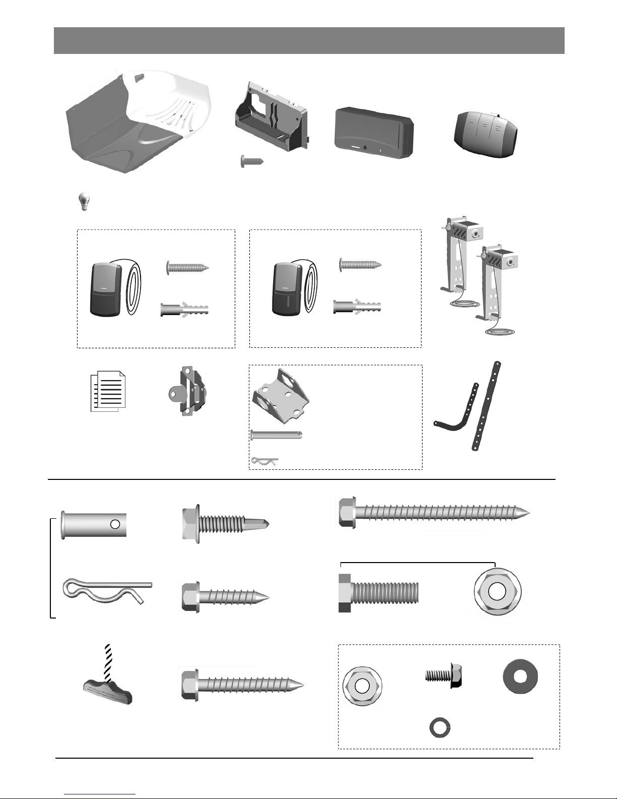
Door Bracket
Inventory
Literature + Safety Labels
Header Bracket
Clevis Pin Long x1
Hitch Pin — Locking Clevis Pins x1
* Optional Accessories
* Items may differ to pictures shown
Opener Unit + Light Lens
( Light bulb is not included)
x 2
Hitch Pin
— Locking Clevis Pins
x 2
Lag Screw 5/16” x 1 5/8”
— Door Bracket / Mounting Opener
Bolt 5/16” -18 x 1”
5/16” Flange Nut
x 6
x 6
x 4
x 2
Clevis Pin — Door arms
5/16” x 1”
INSTALLATION HARDWARE, LOCATED IN HARDWARE BAG (SHOWN IN ACTUAL SIZE 1:1)
Lag Screw 5/16” x 2 1/2”
— Header Bracket / Mounting Opener
x 2
x 4
Emergency Release Handle
+ Rope
Flange Nut
1/4” -20
Self -Threading Screw 1/4” x 1”
— Door Bracket
x 2
Lag Screw 1/4” x 1”
— Photo Eye System
Hexagonal Screw
#
10 - 24 x 1/2”
Spring Washer
#
10
Washer #10
x 1
x 1
x 1
x 1
— Door arms / Mounting Opener
T-rail Assembly
5/16” x 2-1/4”
Door Arms
Battery holster
w/ motion-sensing light
Portable Battery
w/ flash light feature
x 2
Premium 3-Button
Remote
Drywall Anchor
x 2
x 2
Screw #6 x 1-3/8”
Door Control
Console
Door Control
Door Control included in some models
Deluxe Door
Control Console
Drywall Anchor
x 2
x 2
Screw #6 x 1-3/8”
Photo Eye Safety System

4
IMPORTANT INSTALLATION INSTRUCTIONS
WARNING —
To reduce the risk of severe injury or death:
1. READ AND FOLLOW ALL INSTALLATION INSTRUCTIONS.
2. Install only on a properly balanced garage door. An improperly balanced door has the potential to inflict severe
injury. Have a qualified service person make repairs to cables, spring assemblies, and other hardware before
installing the opener.
3. Remove all ropes and remove or make inoperative all locks connected to the garage door before installing opener.
4. Where possible, install the door opener 7 feet or more above the floor. For products having an emergency release,
mount the emergency release within reach, but at least 6 feet above the floor and avoiding contact with vehicles to
avoid accidental release.
5. Do not connect the opener to source of power until instructed to do so.
6. Locate the control button: (a) within sight of door, (b) at a minimum height of 5 feet so small children are not able to
reach it, and (c) away from all moving parts of the door.
7. Install the Entrapment Warning Label next to the wall-mount control button in a prominent location. In case the
adhesive does not adhere on the surface, the label should be attached to the surface by mechanical means.
8. After installing the opener, the door must reverse when it contacts a 1-1/2-inch high object (or a 2 by 4 board laid
flat) on the floor.
IMPORTANT SAFETY INSTRUCTIONS
WARNING —
To reduce the risk of severe injury or death:
1. READ AND FOLLOW ALL INSTRUCTIONS.
2. Never let children operate or play with door controls. Keep the remote control away from children.
3. Always keep the moving door in sight and away from people and objects until it is completely closed. NO ONE
SHOULD CROSS THE PATH OF THE MOVING DOOR.
4. NEVER GO UNDER A STOPPED, PARTIALLY OPEN DOOR.
5. Test door opener monthly. The garage door MUST reverse on contact with a 1-1/2-inch high object (or a 2 by 4
board laid flat) on the floor. After adjusting either the force or the limit of travel, retest the door opener. Failure to
adjust the opener properly increases the risk of severe injury or death.
6. Use the emergency release only when the door is closed. Use caution when using this release with the door open.
Weak or broken springs are capable of increasing the rate of door closure and increasing the risk of severe injury or
death.
7. KEEP GARAGE DOORS PROPERLY BALANCED. See owner’s manual. An improperly balanced door increases
the risk of severe injury or death. Have a qualified service person make repairs to cables, spring assemblies, and
other hardware.
SAVE THESE INSTRUCTIONS.
Read and Follow These Important Safety Instructions
Entrapment Warning Label—Permanent attach next to wall-mounted control button
5
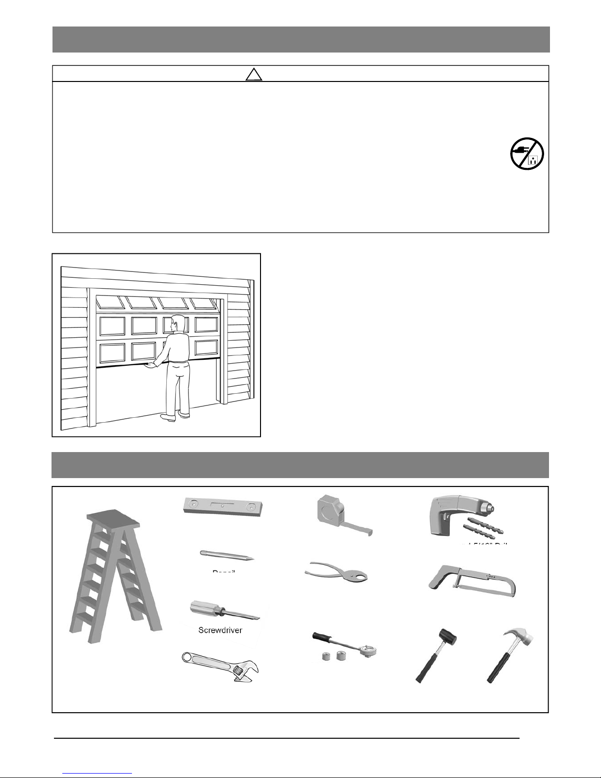
Level
Tape Measure
Hack Saw
Pencil
Drill, 3/16” and 5/16” Drill Bits
Tools Required
Step Ladder
Screwdriver
Hammer
Sectional Garage Door
BEFORE Beginning Installation:
1. Disable locks and remove all ropes connected to the
garage door.
2. Perform the following door test to ensure your door is
balanced and in good working condition.
To Test Your Garage Door
1. Raise and lower the door to check if there is any sticking or
binding.
2. Check for loose hinges, damaged rollers, frayed cables and
damaged or broken springs.
3. Lift the door approximately halfway and release. The door
should stay at the point under proper spring tension.
Call a qualified garage door service technician if your door binds,
sticks or is unbalanced.
!
WARNING
To prevent SERIOUS INJURY or DEATH:
- Before beginning installation of the Opener please complete the following test to ensure that your door is
balanced and in good working condition.
- A poorly balanced door can cause serious injury and damage to the Opener.
- Always have a qualified garage door service technician make any required adjustments and/or repairs to
your door before proceeding with installation.
- DISABLE ALL LOCKS and REMOVE ALL ROPES connected to the garage door BEFORE installing
and/or operating the Opener.
To prevent damage to the door and Opener:
- DO NOT connect power until instructed.
- Operate this Opener with AC 120V/60Hz power supply ONLY.
Adjustable Wrench
Preparation
Pliers
Rubber Mallet
Ratchet with
7/16” & 1/2” sockets
6
!
CAUTION
- DO NOT connect power until instructed.
- To prevent INJURY, keep hands and fingers
away from joints and possible sharp edges.
- Wear gloves when installing chain/belt and cable.
!
WARNING
To prevent SERIOUS INJURY:
- DO NOT connect power until instructed.
- Keep hands and fingers clear from sprocket during operation.
- Wear gloves when installing chain/belt and cable.
- Keep hands and fingers away from joints and possible sharp edges.
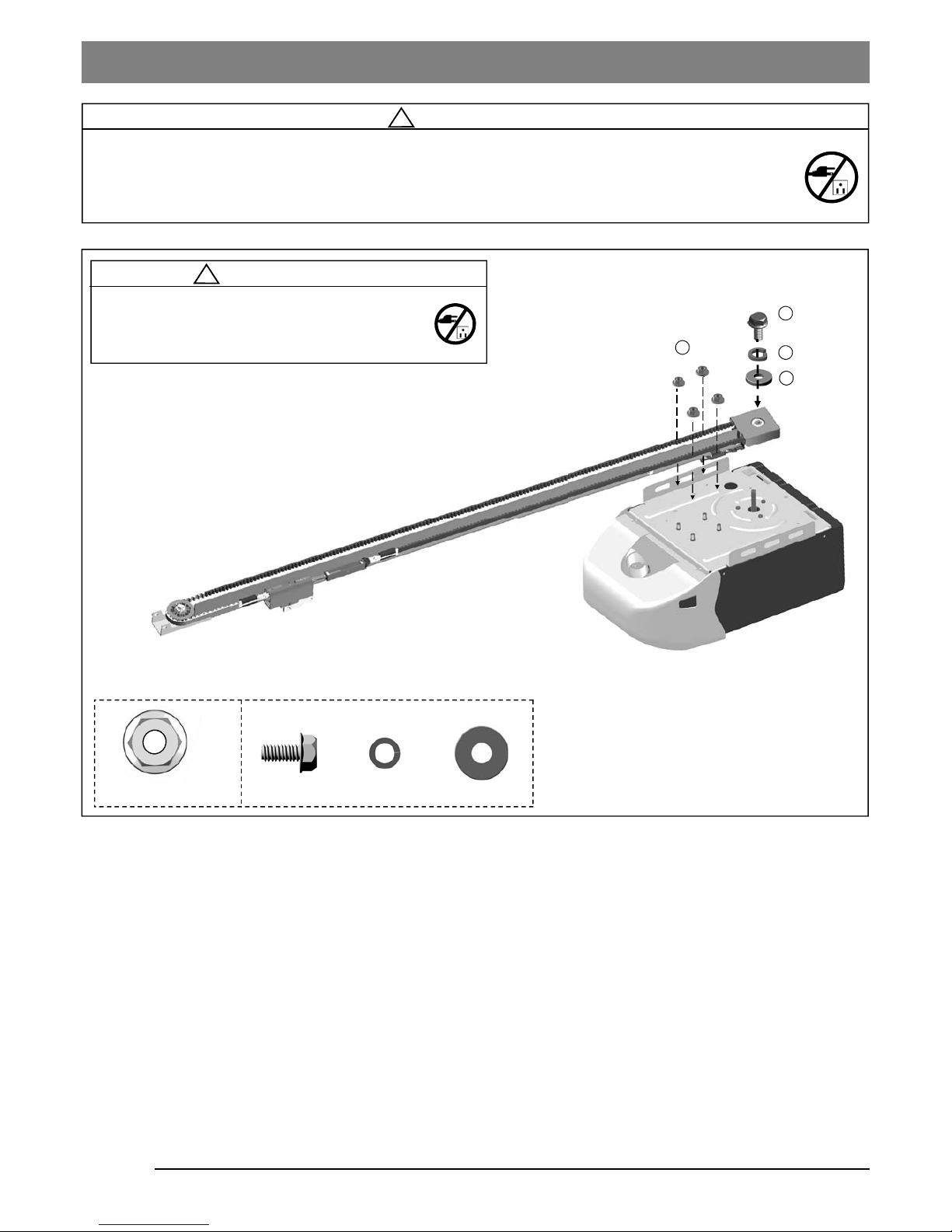
Fig.1
Assembling T-Rail
4
2
3
1
1/4” Flange Nut x 4
Screw Spring Washer Washer
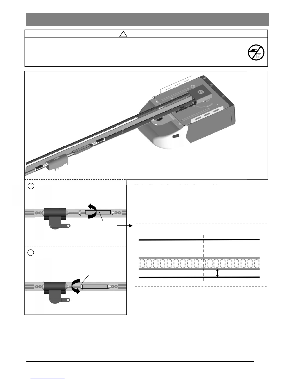
To Assemble the Rail
Align the pre-assembled T-rail on the top of opener in the direction as shown in Fig.1.
Secure the T-rail to the opener firmly using 1/4” flange nut x 4.
Final Step to T-Rail Installation
Fasten the Screw(2) to the motor shaft with spring washer(3) and washer(4) in betwe en.
7
!
WARNING
To prevent SERIOUS INJURY:
- DO NOT connect power until instructed.
- Keep hands and fingers clear from sprocket during operation.
- Wear gloves when installing chain/belt and cable.
- Keep hands and fingers away from joints and possible sharp edges.
Shaft-Linker
Tighten until...
Tighten nut
Flange Nut
2
1/4” (6mm)
Base of Rail
Mid-point of rail assembly
Belt
Top of Rail
Actual Size
1
Note: The chain or belt rail assembly comes pre-tensioned
from the factory. Additional adjustment is not required.
To Re-tension the Belt or Chain
1. Rotate the Shaft Linker towards the Trolley Shaft until the
belt/chain is slightly loose about 1/4” (6mm) above the base
of the rail, referring to the actual-sized illustration below.
2. Tighten the Flange Nut on Trolley Shaft against the
Shaft-Linker.
Tension the Belt / Chain
8
!
WARNING
To prevent SERIOUS INJURY:
- DO NOT connect power until instructed.
- The Header Bracket MUST be SECURELY fastened to the structural support on the mounting wall or
ceiling, otherwise the door may not reverse when required. DO NOT install the Header Bracket over drywall.
- Concrete anchors MUST be used when mounting the Header Bracket into masonry.
- NEVER try to loosen, move or adjust garage door springs, cables, Pulleys, Brackets, or hardware, all of
which are under EXTREME tension.
- Contact a qualified garage door service technician if your door binds, sticks or is unbalanced. An unbalanced
door might not reverse when required.
Mounting Header Bracket
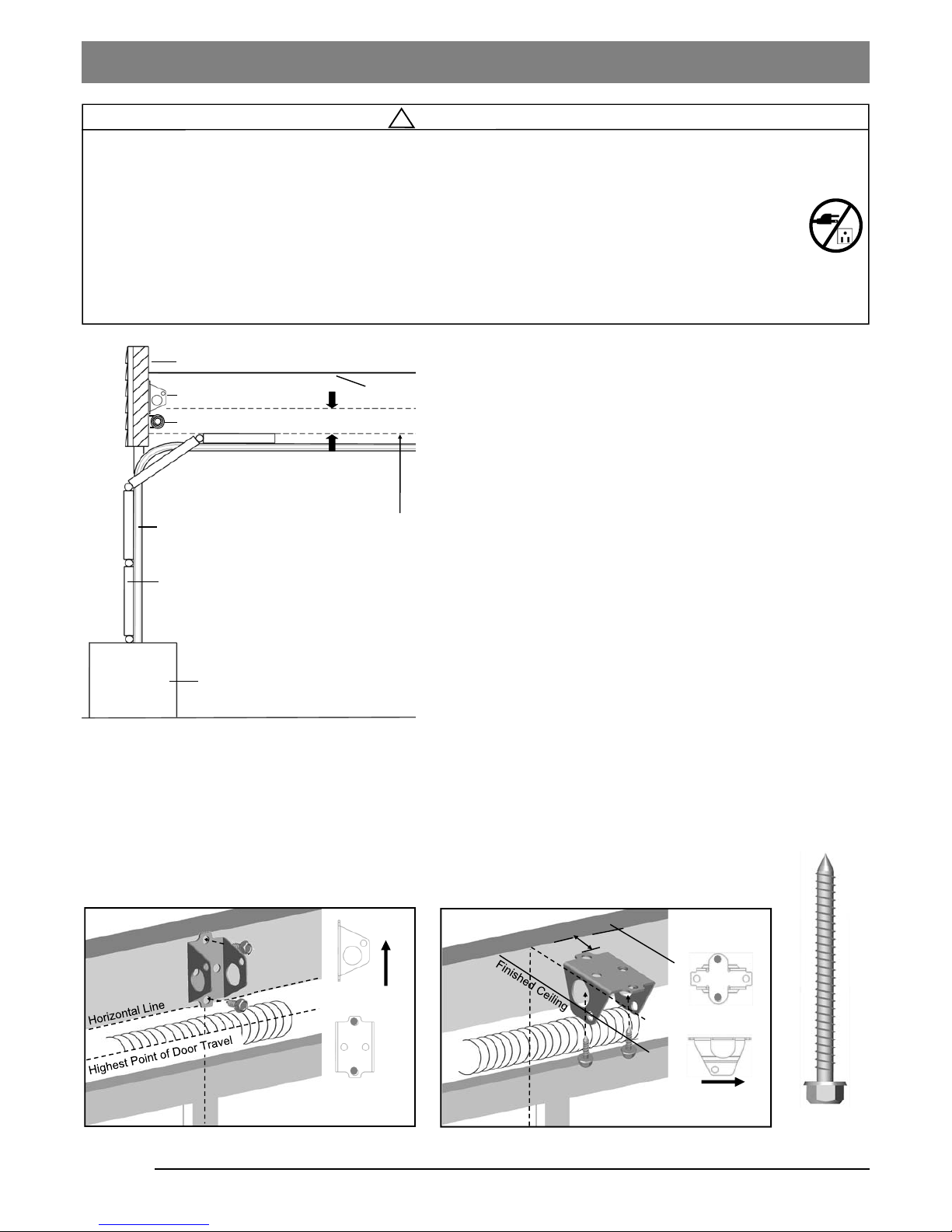
To Install Header Bracket
Note: Installation procedures may vary according to door
type.
1. While inside your garage, close the door and mark the
vertical centerline of the garage door. Extend the line onto
the header wall above the door spring.
2. Open the door to the highest point of travel. Mark a line on
the header wall 2“ (5cm) above the highest point of travel.
Note: DO NOT install the Header Bracket over drywall. In some
installations, it may be necessary to install a 2x4 across two wall
studs to create a suitable location for the Header Bracket.
If installing into masonry, use concrete anchors (not provided).
Wall-Mounting
As shown in Fig.2, place the Header Bracket on the vertical
centerline in direction shown.
Mark and drill two 3/16” holes. Fasten the Header Bracket
securely to a structural support using two 5/16” x 2-1/2” Lag
Screws.
Alternative Ceiling-Mounting
Ceiling-mounting is suggested ONLY when clearance is minimal.
Extend the vertical centerline onto the ceiling as shown in Fig.3.
Center the Header Bracket on the vertical mark, no more than
6” (15cm) from the header wall. Mark and drill holes to fasten the
Header Bracket securely to a structural support.
Fig.1
Ceiling
Header Bracket
Header Wall
2” (5cm) clearance
Door Track
Door
Highest Point of Door Travel
Support block on floor
Door Spring
UP
OPENER
MAX. 6” (15cm)
Vertical Centerline
Lag Screw
5/16” x 2-1/2”
Vertical Centerline
Fig.2 (Wall-Mounting) Fig.3 (Ceiling-Mounting)
9
!
CAUTION
To prevent SERIOUS INJURY:
- DO NOT connect power until instructed.
- REINFORCEMENT is recommended for fiberglass, aluminum or lightweight steel garage doors BEFORE
installing the door Bracket. Contact your door manufacturer for reinforcement options.
Attaching Rail to Header Bracket and Mounting Door Bracket
Fig.1
Fig.3
(a) (b) (c)
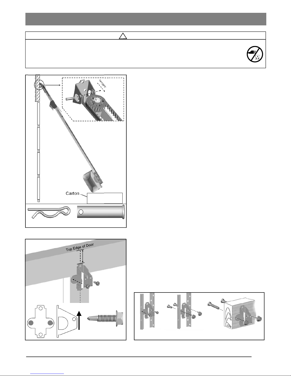
To Attach the Opener to the Header Bracket
1. As shown in Fig.1, use the packaging carton as temporary
support for the Opener. Place the Opener on carton to
prevent damage.
2. Align the mounting hole on the header rail to the mounting
hole on the Header Bracket.
3. Connect the Header Rail and the Door Bracket together
with a 5/16” x 2-1/4” Clevis Pin and lock it in place with a
Hitch Pin.
To mount the Door Bracket
Note: Some door reinforcement kits may provide direct
attachment of the door arm to the reinforcement bracket. If you
have a door reinforcement bracket with this option, skip this step
and proceed with the next step “Mounting Opener to Ceiling”.
1. Position the Door Bracket on the centerline of the door
approximately 2” - 4” (5-10cm) below the top edge of the
door, as shown in Fig.2.
2. Depending on the construction of your door, install using
one of the steps shown if Fig. 3 below:
For steel / lightweight doors with vertical steel
reinforcements / factory reinforced.
(a) Mark and drill two 3/16” holes. Make sure not to drill
through the garage door. Secure the Door Bracket with two
1/4” x 1” Self-Threading Screws (provided) as shown in
Fig.3(a).
(b) Alternative installation: Drill two 5/16” holes through the
door. Secure the Door Bracket using two 5/16” Bolts, lock
washers and nuts (not provided) as shown in Fig.3(b). The
length of bolts will depend on the thickness of your door.
Wood door
(c) Mark and drill two 5/16” holes through the garage door.
Secure the Door Bracket using two 5/16” carriage bolts,
washers and nuts (not provided) as shown in Fig.3(c). The
length of bolts will depend on the thickness of your door.
Note: DO NOT use Self-Threading Screws on a wood door.
Fig.2
Self-Threading
Screw - 1/4” x 1”
UP
Vertical Centerline of Door
2-4” (5-10cm)
Clevis Pin - 5/16” x 2-1/4”
Hitch Pin
Carton
10
!
WARNING
To prevent SERIOUS INJURY or DEATH:
- DO NOT connect power until instructed.
- Install the Opener at least 7 feet (2.13m) above the floor.
- Fasten the Opener SECURELY to STRUCTURAL SUPPORTS of the garage to prevent falling.
- If installing Brackets to masonry, concrete anchors (not provided) MUST be used.
Mounting Opener to Ceiling
Angle Iron not provided
Fig.1
Fig.2
Fig.3
Finished ceiling
Angle Iron not provided
Finished ceiling
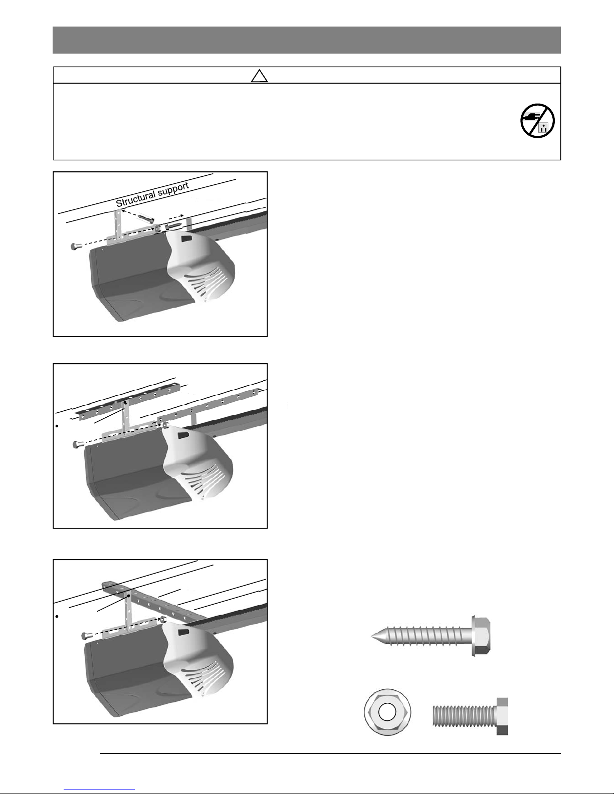
To Mount the Opener to Ceiling
The three most common installation options are shown in
Fig.1-3.
Fig.1 shows mounting the Opener directly to structural
support on the ceiling. Fig.2 and 3 show mounting on a
finished ceiling, with heavy duty angle iron*.
*(angle iron not included)
Determine the mounting option that works best for your
application and follow installation steps below:
1. Raise the Opener and rail assembly and temporarily place it
on a stepladder.
2. Position the Opener and rail assembly so that it is aligned to
the center line of the garage door. If the Header Bracket
was mounted off center, align the Opener with the Header
Bracket.
3. Measure the distance from each side of the Opener to the
structural supports.
4. Cut both Hanging Brackets* to appropriate length
*(Hanging Bracket not included)
5. Drill 3/16” holes in the structural supports.
6. Secure one end of each of the Hanging Brackets to the
structural supports using 5/16” x1-5/8” Lag Screws
(provided).
7. Secure the Opener to the Hanging Brackets and secure
each side with a 5/16”-18x1” Bolt and Flange Nut
(provided).
8. Move the door manually to check clearance between
highest point of travel of the door and rail. If the door hits the
rail, raise the Header Bracket or adjust the mounting of
Opener.
9. Remove the ladder ONLY when the Opener is securely
mounted to the structural supports.
Lag Screw 5/16” x 1-5/8”
Bolt 5/16” - 18x1”
5/16” Flange Nut
Fastening Hanging Brackets to structural supports
Securing Opener to Hanging Brackets
Bolt / Lock Washer / Nut
not provided
Bolt / Lock Washer / Nut
not provided
 Loading...